Review

Progress of the Pyrolyzer Reactors and Advanced Technologies for Biomass Pyrolysis Processing

1
Department of Chemical & Petroleum Engineering, United Arab Emirates University (UAEU), Al-Ain 15551, United Arab Emirates
2
Department of Sustainable and Renewable Energy Engineering, University of Sharjah, Sharjah 27272, United Arab Emirates
3
Department of Chemical Engineering, Lahore Campus, COMSATS University Islamabad, Raiwind Road, Lahore 54000, Pakistan
4
School of Environmental Engineering, University of Seoul, Seoul 02504, Korea
5
Institute for Sustainable Industries and Liveable Cities, Victoria University, PO Box 14428, Melbourne 8001, Australia
6
School of Chemical and Material Engineering, National University of Science and Technology, Islamabad 44000, Pakistan
7
Department of Civil and Environmental Engineering, University of Sharjah, Sharjah 27272, United Arab Emirates
8
Department of Chemical Engineering, Universiti Teknologi PETRONAS, Bandar Seri Iskander 31750, Malaysia
9
Department of Zoology, Lahore College for Women University, Lahore 54000, Pakistan
*
Authors to whom correspondence should be addressed.
First coauthors with equal contributions.
Sustainability 2021, 13(19), 11061; https://doi.org/10.3390/su131911061
Submission received: 2 August 2021 / Revised: 20 September 2021 / Accepted: 30 September 2021 / Published: 7 October 2021

Abstract

:
In the future, renewable energy technologies will have a significant role in catering to energy security concerns and a safe environment. Among the various renewable energy sources available, biomass has high accessibility and is considered a carbon-neutral source. Pyrolysis technology is a thermo-chemical route for converting biomass to many useful products (biochar, bio-oil, and combustible pyrolysis gases). The composition and relative product yield depend on the pyrolysis technology adopted. The present review paper evaluates various types of biomass pyrolysis. Fast pyrolysis, slow pyrolysis, and advanced pyrolysis techniques concerning different pyrolyzer reactors have been reviewed from the literature and are presented to broaden the scope of its selection and application for future studies and research. Slow pyrolysis can deliver superior ecological welfare because it provides additional bio-char yield using auger and rotary kiln reactors. Fast pyrolysis can produce bio-oil, primarily via bubbling and circulating fluidized bed reactors. Advanced pyrolysis processes have good potential to provide high prosperity for specific applications. The success of pyrolysis depends strongly on the selection of a specific reactor as a pyrolyzer based on the desired product and feedstock specifications.

1. Introduction

A dependable, clean, and economical energy provision is of paramount significance for the economy, environment, and society, and will continue to be cutting-edge for the 21st century [1]. Over the past few decades, CO2 emissions have increased, and many other environmental pollutants are responsible for the greenhouse effect, causing global warming to planet Earth [2]. Other than carbon emissions and environmental issues, the energy from fossil fuels has sustainability issues [3]. To solve this issue, international organizations have made many efforts to meet energy demands without affecting the environment using renewable and carbon-neutral sources. In this scenario, the focus of many countries is now on renewable and green energy technologies and the implementation of policies for reducing carbon emissions [4].
Among the various renewable energy technologies, biomass is the most profuse and low carbon emission bioenergy resource. Biomass releases the same amount of CO2 consumed during photosynthesis for its growth and works on the principle of a carbon fixation process [5]. Therefore, biomass is a carbon-neutral fuel by eliminating the increased CO2 levels and landfill methane emissions. Hence, landfilling and dumping will decrease steadily [6]. Biomass has clear environmental advantages and reduces the risks that various carbon emissions are causing to the ecological balance [7]. According to the World Energy Assessment report, approximately 65% of the total energy supply by renewable energies comes from biomass [8]. This will meet approximately 11–12% of the world’s total energy consumption [9]. Other advantages of biomass include a stable supply for sustainable energy, very low sulfur content, economic availability of biomass as a feedstock, and syngas production for many poly-generation purposes [10].
Biomass consists of a wide range of renewable biological resources, such as crop residues, wood and forestry residues, municipal solid wastes, spent coffee grounds, and other energy crops for biohydrogen and biofuels recovery [11]. The exploitation of biomass for energy production meets the dual goals of fuel security and a reduction in CO2 emissions [12]. Biomass stores solar energy as chemical energy that is extracted by the breakdown of bonds [13]. The energy in biomass can be recovered as biofuels via thermochemical conversion and biochemical conversion processes. Biochemical conversion implies fermentation and anaerobic digestion to transform biomass into liquid and combustible gaseous fuels [14]. Recently, membrane-integrated processes have emerged as a potential alternative to recover and separate biofuels, biogas, biohydrogen, waste gases (e.g., CO2 during waste streams), and biomass processing, such as wastewater and gases [15]. The thermochemical process adopts pyrolysis, combustion, and gasification technologies to convert biomass into multiple poly-generation purposes [16].
Pyrolysis is an established thermochemical process for converting biomass materials into bio-oil, gaseous products, and liquid fuel. The process can be categorized into slow, fast, and flash pyrolysis [17]. Each pyrolysis type has different products and their corresponding compositions [18].
Pyrolysis occurs in an inert atmosphere by applying thermal heat to change biomass into numerous fuels, such as char, gas, and liquid oils. The liquid fuel is a combination of dozens of oxygenated organic compounds [19]. Multiple products are formed depending on the various operation conditions, such as the rate of heating, operating temperature, residence time, and biomass particle size [20]. The amounts of lignin, cellulose, and hemicellulose, which are leading polymers of biomass, also contribute to the composition of the final products [21]. Compared to thermochemical conversion processes, such as combustion and gasification, pyrolysis occurs at moderately lower temperatures (400–600 °C) and is generally preferable because the pyrolysis products, mainly char and liquid fuels, are easy to store and transport [22].
Considerable research has been conducted into the pyrolysis of different materials, including biomass and, most recently, e-waste materials such as electronics scrap components. Pyrolysis has numerous advantages as compared to other thermochemical conversion processes, such as [23]:
1.
It is a simpler and relatively cheaper conversion process.
2.
Pyrolysis is suitable for a wider variety of feedstock.
3.
It reduces the landfill requirements and greenhouse gas (GHG) emissions.
4.
It has very little water pollution potential.
5.
Pyrolysis reactor construction is relatively rapid process.
Pyrolysis efficiency is the thermal efficiency obtained as the ratio of the difference between the overall heating values of the pyrolytic products and the total thermal energy utilized for processing the sample. Pyrolysis is a well-known process of producing high energy-density biofuels and chemicals [24]. Wang et al. [25] presented a comprehensive overview of the pyrolysis mechanisms of three biopolymers in biomass materials and highlighted the complexities in their structure. Sharma et al. [26] conducted a critical review of pyrolysis modeling to highlight the gaps in the technology and explore new opportunities for integrating biomass pyrolysis models of disparate scales. Kan et al. [27] published a comprehensive review of the pyrolysis product properties and effects of pyrolysis parameters. They reported that the heating rate and temperature are the main influential parameters affecting the pyrolysis yield and quality. Dai et al. [28] published a review on understanding the chemistry of non-catalytic and catalytic pyrolysis processes. They introduced recent progress on producing value-added hydrocarbons, phenols, anhydrosugars, and nitrogen-containing compounds from the catalytic pyrolysis of biomass over zeolites and metal oxides via different reaction pathways. The pyrolyzer reactor in the biomass pyrolysis process is the primary component used to convert biomass into valuable products. Several review papers on the biomass pyrolysis process are available, but the authors found few studies on the scope of biomass pyrolyzers. Most review papers on biomass pyrolysis presented experimental and modeling studies in general. Few articles explained the characterization of the products (bio-oil and bio-char). There are also review papers available on the pyrolysis process parameters, the catalyst used in the reactions, and the upgradation of products. Garcia-Nunez [29] presented a study of different reactors used in biomass pyrolysis, but the review paper presented the pyrolysis technologies from a historical perspective. This review follows these former summaries and many others. Where suitable, particular topics previously sufficiently covered in earlier reviews are summarized or the corresponding review paper is referenced. This review provides a detailed evaluation of biomass pyrolysis technology, which includes the selection of biomass feedstock, treatment of biomass material, choice of required pyrolysis process, and finally, pyrolysis in a suitable reactor. This review paper comprehensively discussed biomass pyrolysis technology covering all the aforementioned biomass pyrolysis stages from feed selection to final product formation; special emphasis is made on biomass pyrolysis reactors. Biomass pyrolysis processes are categorized with respect to (w.r.t) reactor type. This review paper is the first to highlight the research on biomass pyrolysis processes in terms of the different pyrolyzer reactors and advanced pyrolyzers. This review article will be of significant interest to researchers in this field. Furthermore, the current review paper will help in the research and development of biomass pyrolysis processes. The review paper also highlights the advanced pyrolyzer technologies and reactors that further enhance the renewability of the pyrolysis process. The review paper contributes significantly to the field of research by critically analyzing fast pyrolysis, slow pyrolysis, and advanced pyrolysis processes.

2. Conversion Mechanism of Biomass by Pyrolysis

As the biomass material is heated, the chemical structure of the polymers inside the matrix of its residue changes. The heating and rearrangement reactions release volatile compounds [30]. After these primary reactions, some unstable, volatile compounds are further converted. Hence, biomass conversion reactions can be categorized as primary and secondary reactions [31].

2.1. Pyrolysis Primary Conversion Mechanisms

Lignin, cellulose, and hemicellulose, commonly known as biopolymers, are the core ingredients in biomass. The conversion reaction of these compounds presents the foremost characteristics. The pathways for breaking the various chemical bonds can be described by the following three pathways [32].

2.1.1. Mechanism of Char Formation

The solid residue left after the anaerobic thermal heating of biomass is called char. The char has a polycyclic aromatic structure [33]. The route is dominated by the inter and intramolecular reorganization of the molecular structure, which results in higher thermal stability and filigree of residue [34]. The formation of benzene rings and the grouping of rings is the main mechanism in this pathway. These rearrangements result in the release of incondensable gases and moisture within the biomass material [35].

2.1.2. Mechanism of Depolymerization

The depolymerization phenomenon in this pathway involves the breakdown of biopolymers (lignin, cellulose, and hemicellulose) into separate units called monomers [36]. The degree of polymerization is reduced until the molecules formed become volatile. The molecules condensing at room temperature are found as a liquid fraction [37].

2.1.3. Mechanism of Fragmentation

Fragmentation entails polymer covalent bonds. The linkages also occur between various monomers of the polymer [38]. This pathway is responsible for releasing many incondensable gases and various small chained organic compounds condensing at room temperature [39].

2.2. Pyrolysis Secondary Conversion Mechanisms

The reactor temperature is essential in the second conversion mechanism of biomass. When the reactor temperature causes the release of unstable, volatile compounds, these volatile compounds can undergo further secondary reactions, such as cracking or recombination. Cracking constitutes the breakdown of volatile compounds into lower-molecular-weight compounds [40]. There is some resemblance between the products obtained from cracking and fragmentation because the breaking of the same chemical bonds can occur inside the polymer or within the volatile compounds [41]. Recombination or recondensation is the reverse of cracking and involves the formation of higher molecular weight compounds. The newly formed compounds are mostly non-volatile in the reactor conditions. This pathway is also responsible for the generation of additional secondary char [42].

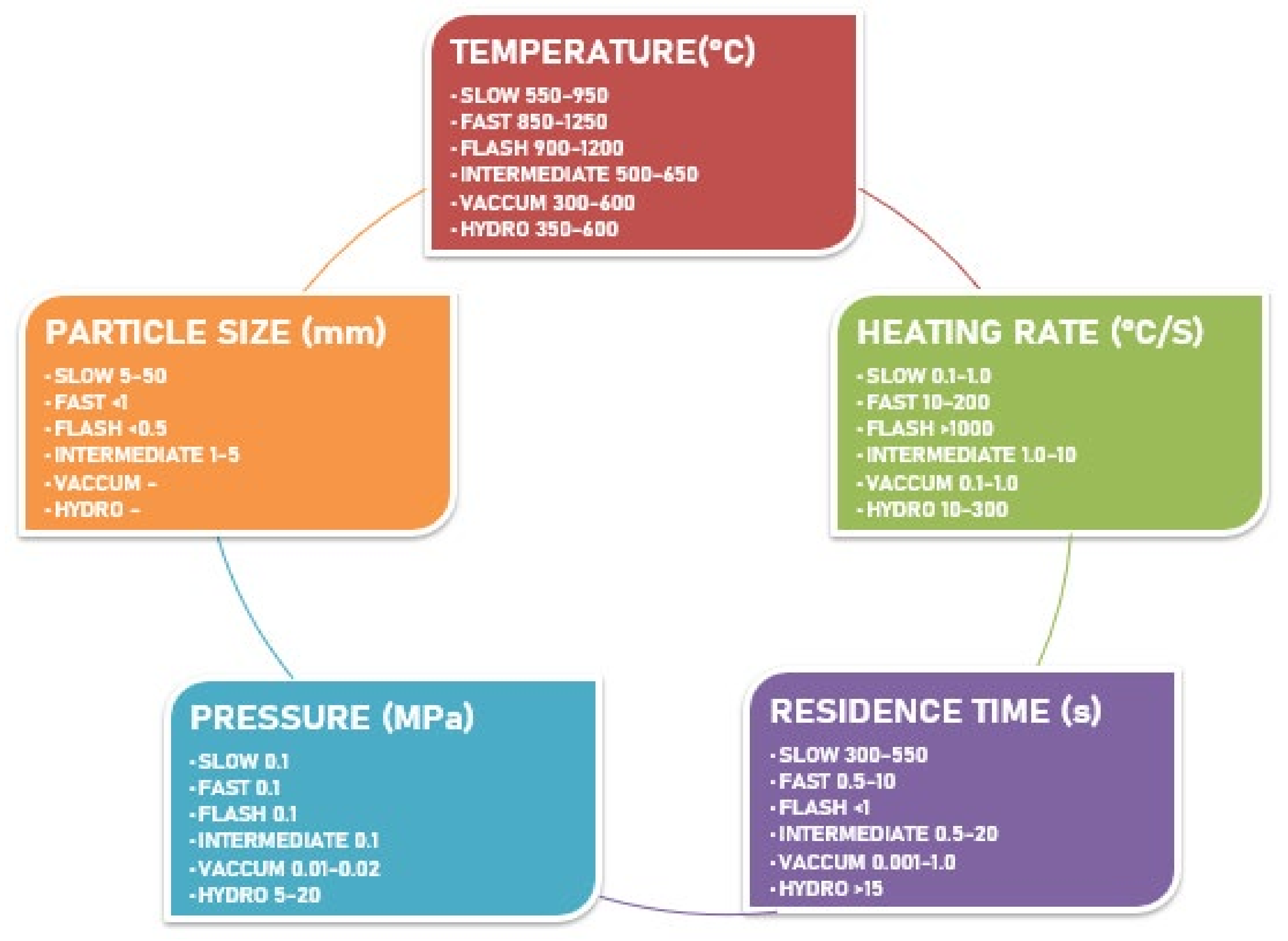
2.3. Principle of Pyrolysis and Product Distribution

Biomass feedstock is thermally degraded in the absence of oxygen. This phenomenon is a combination of several complex reactions in the reaction zone. Volatile biomolecules of the biomass material are released by heating, which are then transformed into bio-oil by condensation. The inert atmosphere heats the biomass above its thermal stability limit, bringing more stable products and solid residue. The main advantage of the inert medium is that biomass materials are heated without combustion [43]. As explained in detail above, the pyrolysis process consists of two stages: primary pyrolysis and secondary pyrolysis. Primary pyrolysis involves the formation of different carbonyl, carboxyl, and hydroxyl groups as the biomass material splits up and devolatilizes into different constituents. In the devolatilization process, biomass material is decarboxylated, dehydrated, and dehydrogenated [44]. The main conversion process occurs in secondary pyrolysis, where heavy compounds are cracked into char and gases (CH2, CO2, CO, and CH4). Subsequently, the volatile gases are condensed into bio-oil. The proposition of these solid and liquid products depends on the pyrolysis conditions, such as temperature, residence time, and heating rate [45]. The general pyrolysis reaction is as follows [46]:
(C6H6O6)n → (H2 + CO + CH4 + …. + C5H12) + (H2O + CH3OH + CH3COOH + ….) + C
The first part of the product side (H2 + CO + CH4 + …. + C5H12) is a mixture of various combustible gases known as synthesis gas; the second part (H2O + CH3OH + CH3COOH + ….) is a mixture of different liquids that form bio-oil, and finally a solid yield (char). Pyrolysis processes significantly affect the product distribution according to their operating parameters. The product distribution is based on the temperature, heating rate, residence, particle size, and pressure. Based on these operating parameters, the pyrolysis technology is classified into different sub-categories. Figure 1 provides an overview of the pyrolysis process based on these parameters.
Slow pyrolysis has a slow heating rate (0.1–1 °C/s), prolonged residence time (5–30 min), and moderate temperature (400–500 °C). Charcoal or char is the main product of the slow pyrolysis of biomass. Under these conditions, the pyrolysis conversion reaction leans towards the maximum yield of solid product char. On the other hand, bio-oil and synthesis gas are also produced, albeit in comparatively smaller quantities. The mechanism of a more solid product in slow pyrolysis is that the long residence time and lower heating rate promote the secondary reactions to completion. A longer vapor residence time allows the elimination of vapors produced during secondary reactions heading towards a higher char yield [47].
Fast pyrolysis has a higher operating temperature range (800–1250 °C), a higher heating rate (10–200 °C), and a very short residence time (1–10 s). These conditions favor the biomass pyrolysis reaction mechanism towards producing more liquid fuel. The main product of the fast pyrolysis process is bio-oil (65–75%), with smaller amounts of biochar (10–25%) and non-condensable gases (10–20%). The aim is to exceed the temperature such that decomposition is not favored over char formation. The very high heating rate converts the biomass material to condensable vapors before it can form char. A higher heating value (HHV) of the bio-oil produced is half the HHV of crude oil [48].
Flash pyrolysis is an advanced form of fast pyrolysis. The conditions that distinguish it from the fast pyrolysis process are the extremely high heating rate of 1000 °C/s. The operating temperature is kept between 900–1200 °C, and the biomass feedstock is exposed to these conditions for very small residence times (0.1–1 s). Compared to fast pyrolysis, the bio-oil yield further increased in flash pyrolysis (>75%) with significantly smaller amounts of solid and gaseous products. The operating parameters required for flash pyrolysis are also hindrances in industrial-scale applications [49].
The intermediate pyrolysis process is adopted to make a balance between liquid, solid, and gaseous products. The operating conditions for pyrolysis are kept between slow and fast pyrolysis processes so that a balance should be drawn in the ratio of the product. The typical intermediate pyrolysis conditions are 500–650 °C, 0.1–10 °C/s, and 300–1000 s residence time. Intermediate pyrolysis leans more towards fast pyrolysis with bio-oil yield (40–60%), biochar (15–25%), and non-condensable gases (20–30%). An advantage of bio-oil produced by the intermediate pyrolysis process is that it has a lower tar content and can be used directly for thermal heat generation [50].
Hydropyrolysis is a new emerging technology to produce high-quality bio-oil from a biomass feedstock. The operating temperature is the same as fast pyrolysis with the addition that biomass feedstock is operated at elevated pressures (5–20 MPa) and mixed with hydrogen or hydrogen-based material. The presence of hydrogen at high pressures and temperatures reduces the oxygen content in the bio-oil produced and hinders the formation of solid char [51].
Vacuum pyrolysis is the conversion of biomass feedstock under low-pressure conditions (0.05–0.20 MPa), and all other conditions for the slow pyrolysis process are maintained. On the other hand, the difference between the two processes is the procedure for eliminating vapors from the reaction region. The vacuum is used for vapor removal instead of a purge gas, which is used mainly in other pyrolysis techniques. Another advantage of vacuum/low pressure is that the biomass components are decomposed at relatively lower temperatures. The rapid removal of vapors during the primary pyrolysis mechanism allows a better bio-oil yield. The bio-oil yield is improved with vacuum pyrolysis, and the biochar produced has high porosity [52].
In biomass pyrolysis, the end products depend on the reaction parameters. The reaction parameters determine the yield and quality of the products. Biomass pyrolysis is used mainly to obtain a specific type of product. The following operating parameters affect the end product in the biomass pyrolysis conversion processes [53]:
1.
Effect of the biomass particle size
2.
Effect of the operating temperature
3.
Effect of the heating rate
4.
Effect of the residence time
5.
Effect of pressure
6.
Effect of the catalyst
7.
Effect of the pyrolysis bed-height
8.
Effect of the carrier gas flow rate
The coarser particle size of the biomass feedstock supports char formation. The heat must travel long distances from the material surface to its core; this higher temperature difference favors solid char production. Furthermore, the vapors formed must travel a longer distance through the char layer, which increases char formation. On the other hand, smaller and refined particles are recommended for producing condensable gases that form bio-oil [54]. Siyi Luo et al. [55] performed the pyrolysis of three different biomass materials (garbage, wood, and plastic) and investigated the effect of particle size on the pyrolysis process. The outcomes from the investigation showed that for all the biomasses, particle size affects pyrolysis product yields and composition: smaller particle size results in higher gas yield with lower tar and char; the decrease in particle size can increase the hydrogen and carbon monoxide contents of gas, as well as the ash and carbon element contents in the char. An increase in temperature favors the formation of more bio-oil and non-condensable gases and results in char formation. Elevated temperatures accelerate the thermal cracking of higher hydrocarbons heading towards the formation of more liquid and gaseous products [56]. Feedstock heating rates greatly influence the nature and composition of the pyrolysis products. Lower heating rates ensure the reduction in secondary pyrolysis reactions. This favors the formation of more solid char. In contrast, a high heating rate supports the fragmentation and rapid thermal degradation of the biomass feedstock, resulting in more gaseous and liquid end-products [57]. Dengyu Chen et al. [58] investigated the effect of heating rate (10, 30, and 50 °C/min) on the pyrolysis process. The outcomes showed that in the BET surface area of biochar, the higher heating value of non-condensable gas and bio-oil reached the maximum values of 411 m2/g, 14 MJ/m3, and 14 MJ/kg, under the condition of 600 °C and 30 °C/min, 600 °C and 50 °C/min, and 550 °C and 50 °C/min, respectively. Higher pyrolysis temperature and heating rate contributed to achieving both higher mass yield and energy yield of the non-condensable gas.
The residence time of the pyrolysis process determines the end-product distribution. A prolonged residence time promotes polymerization of the pyrolysis constituents and provides sufficient time to react. Low residence time and moderate temperature endorse the formation of char. If the residence time is kept very small, then polymerization is not completed. A shorter residence time promotes the formation of condensable gases and bio-oil [59]. The biochar yield is increased by conducting biomass pyrolysis at pressures higher than ambient pressure. This is because elevated pressure lengthens the residence time of the constituents and supports secondary carbon formation. The pyrolysis vapors are also decomposed on the carbonaceous material and form a char [60]. Bin Zhao et al. [61] investigated the effect of residence time, heating rate, and temperature on the pyrolysis of rapeseed. The outcomes have explained the connection between rapeseed stem biochar and its pyrolysis conditions. The surface area and morphology were considerably affected by residence time, which is often ignored in the scientific literature.
The catalytic biomass pyrolysis process is classified as a primary and secondary catalytic pyrolysis process. The primary catalytic biomass pyrolysis conversion process involves the mixing of catalyst material with the biomass feedstock before feeding it into the reactor. Mixing can either be performed mechanically (dry mixing) or by wet impregnation. Secondary catalytic biomass pyrolysis conversion deals with the treatment/upgrading of the pyrolysis products in a downstream reactor. Catalytic biomass conversion provides an improved product distribution [62]. Biomass pyrolysis reactors are classified as fixed and fluidized beds. The reactor type influences the pyrolysis end-product distribution. The bed height is an important parameter in both types of pyrolysis reactors. Ahmed et al. [63] reported that biochar yield was decreased after increasing the bed height to a certain level. Nitrogen is the most widely used purge gas carrier because of its inert nature. During the pyrolysis of biomass, a large quantity of vapors is formed, which, if not purged, can become involved in the secondary reactions. This changes the composition and nature of the end-products [64]. Expected yields of products from different types of biomass thermal conversion are shown in Figure 2.

3. Biomass Feedstock Availability and Economic Analysis

With an annual production capacity of 220 billion tons per year, biomass is the world’s largest source available for energy generation. In the future, biomass could be deemed the sole source of energy generation, supplying multiple types of gaseous, liquid, and solid products. Biomass contains cellulose, hemicellulose, and lignin as its main constituents [66]. The heating value of any biomass material depends on its inherent composition constituents. For example, for a typical lignocellulosic biomass, its composition ranges as cellulose (30–50%), hemicellulose (15–35%), and lignin (10–20%) [67]. Biomass materials are appropriate feedstock for pyrolysis processes to transform them into a wide range of fuels. These biomass feedstocks for the pyrolysis process can be grouped into seven varieties [68].
Forest residue is the leading quantity, with an annual global production capacity of approximately 31 billion tons. Forest waste materials are the most abundant lignocellulosic waste materials rich in lignin (25–35 wt.%). Forest waste materials include leaves, stems, wood, and bark. These offer a great opportunity to produce multiple products using all thermochemical conversion processes [69]. Another main concern for forest waste utilization is that it is a potential fire hazard. Forest waste materials are high carbon (44–53%) lignocellulosic materials with very little ash content (0.3–8 wt.%). The average lower heating value of forest waste materials varies between 15.4–20.5 MJ/kg, with pyrolysis producing an average bio-oil yield of 35.1 wt.% and energy recovery of 37.2% [70]. Owing to the higher water content in bio-oil (20–30 wt.%), the bio-oil yield and energy recovery values are slightly lower than other protein-rich and high lignin lignocellulosic materials [71].
Food waste materials are produced in every country from domestic households and restaurants. These materials provide the second most sustainable source of biomass, with an annual production capacity of 1.3 billion tons per annum. These biomass materials also contain a heterogeneous range of compounds (proteins, lipids, and digestible sugars) suitable for energy-intensive bio-oil production [55]. The products from the pyrolysis of food waste materials vary greatly according to the types, collection method, season, and origin. An average lower heating value varies between 26–34 MJ/kg, and energy recovery is moderate (30%) compared to other biomass materials. The pyrolysis of some food waste results in a bio-oil yield between 18–22 wt.% [72].
The agriculture sector offers a third sustained source of biomass waste of nearly 1.0 billion tons of annual biomass waste annually. These waste materials are rich in protein and lignin, which are suitable feedstock for the pyrolysis process. Agricultural waste (corn stalk and rice husk) contains cellulose (35 wt.%), hemicellulose (24 wt.%), and lignin (22 wt.%) [73]. In the category of agricultural waste material, herbaceous plants offer higher cellulose content (>38 wt.%) and lower lignin (<20 wt.%). Dedicated plants grown especially for energy production (also referred to as energy crops) have higher biomass production and better glucans, lignin, and xylans content and generate less ash. Therefore, these dedicated plants produce a higher bio-oil yield and offer more energy recovery [74]. Agricultural waste material and dedicated plants have a higher volatile matter (73–88 wt.%) and good energy content (16–30 MJ/Kg) than all other categories of biomass materials suitable for bio-oil production. The average bio-oil yield and energy recovery values from agricultural waste and dedicated plants are approximately 45 wt.% and 65 wt.%, respectively [75].
De-oiled seedcake is a major by-product of the biodiesel industry that is usually obtained after the oil extraction from the Jatropha curcas, canola, and pennycress. The residual oil in seedcakes gives them a higher energy content than lignocellulosic materials [76]. Typical de-oiled seedcake contains lipids (2–20%), a good protein amount (10–40%), very high volatile matter (70–90%), and lower ash content (0.5–10%). Bio-oil yield from the pyrolysis of de-oiled yield has an average value of 40 wt.% and energy recovery of approximately 55% [77]. Crude glycerol is also obtainable as an inexpensive waste by-product from the biodiesel industry and has tremendous potential as a feedstock/co-feedstock in the pyrolysis process. A typical crude glycerol from biodiesel industry contains 35–40% C, 8–10% H2, 0.30–0.70% S, and 45–55% O2. The highest gas yield with up to 60 v/v% H2 can be obtained by the pyrolysis of crude glycerol [78].
Spent grains from the beer brewing industry are also generated in quantities of millions of tons every year as the brewing industry is expanding. These spent grains, which have a lower moisture content, are likely to decompose rapidly, making them highly suitable for biofuel production [79]. Compared to other lignocellulosic biomass materials, they contain fewer polysaccharides, a lower activation energy for decomposition, and a high level of proteins (20–30 wt.%). They usually have a lower ash content (2–7 wt.%) and a heating value of 20–25 MJ/kg. The average bio-oil yield and energy recovery were recorded to be 46 wt.% and 65 wt.%, respectively [80].
Municipal solid waste includes waste materials from pulp and paper, leather industry, yard waste, food waste from restaurants, household waste materials, plastics, and textile waste materials. Sewage sludge is a waste material from wastewater treatment plants and is an ash-rich solid waste material [81]. In the USA (2015), out of 260 million tons of municipal solid waste produced, only half was landfilled, and less than a quarter was recycled [82]. Both municipal solid waste and sewage sludge have tremendous potential to be converted to useful energy fuels/thermal heat by incineration and anaerobic digestion processes (methane production), but it also can be used as a feedstock in thermochemical conversion processes [83]. On average, the bio-oil yield from municipal solid waste is approximately 30 wt.%, which is lower than other biomass materials because it has many inorganic materials (20–45 wt.%) and lower volatile contents (45–65 wt.%). Energy recovery from both municipal solid waste and sewage sludge is approximately 60 wt.% [84].
Anaerobic digestion (AD) is a biological conversion process of biomass conversion (mainly animal manure). The process produces biogas, which is a blend of CO2 (30–60%) and CH4 (40–70%). Anaerobic sludge is a solid residue obtained from anaerobic digestion, which is 40–50% of the original organic material [85]. Anaerobic sludge can be a feedstock and, more frequently, a co-feedstock in the pyrolysis process to produce bio-oil because it is biologically stable and contains abundant organic molecules. The digestate has physical and chemical properties similar to municipal solid waste and sewage sludge. The lower heating value of the digest matches that of raw sewage sludge (SS) [86]. The average bio-oil yield and energy recovery from the pyrolysis of sludge is 30.5 wt.% and 56 wt.%, respectively. The bio-oil yield and energy recovery values are slightly lower than municipal solid waste and sewage sludge because much of the energy is used in the anaerobic digestion process [87].
Algae are not included in these seven categories because it contains very low lignin and crystalline cellulose contents. Hence, it is a barrier to its thermochemical energy conversion potential. Nevertheless, other pathways are available to convert algae into biodiesel and value-added products [88].
Feedstock type has a significant effect on the product distribution of the pyrolysis process, physiochemical properties of pyrolysis products, and reaction rate. The characteristics of biomass feedstock that affect the pyrolysis products are as follows [89]:
  • Feedstock particle shape and size;
  • Bulk density;
  • Elemental and chemical composition;
  • Energy content (MJ/Kg);
  • Protein, lipid, extractives, and ash content.
Therefore, the pyrolysis of the same biomass feedstock from various origins will not give the same product distribution because it will vary in its composition [90]. Each feedstock has unique physiochemical properties; hence, a specific pyrolysis process for different feedstock gives different product distributions [91]. Table 1 lists the chemical composition analysis of different biomass materials. The biomass feedstock properties can be improved using various techniques. Moreover, lignocellulosic materials with different percentages of cellulose, hemicellulose, and lignin are capable of producing pyrolysis products.
Table 2 presents an overview of chemical composition of different lignocellulosic biomass materials capable of producing pyrolysis products.
The economy of the pyrolysis process mainly links with the abundance of biomass resources. The commercialization aspect of the pyrolysis technology to produce various chemicals and fuels depend on the production parameters and their comparison with fossil-fuel products. Briefly, the economy of the process does not depend on a single factor. Hence, there is a difference in the life cycle production costs of products from pyrolysis [101].
Table 3 lists the economic analysis of some biomass feedstocks, such as the cost of the pyrolysis products depending upon the feedstock, pyrolysis plant capacity, product yield, selection of pyrolysis technology, and discount or subsidy rates.
The economics also vary with local taxes, raw material transportation, utilities, labor wages, maintenance, and waste disposal. The pyrolysis process economy is also influenced by how the feedstock is produced, how it might be sourced, the collection method, and the processing technique [107]. Zhang and Kung [108] reported that the collecting cost for rice straw (agricultural waste) is lower than the harvesting costs of dedicated energy crops. Popp et al. [109] reported that transportation cost has a significant effect on the economy of pyrolysis products. One way to increase the profitability of the pyrolysis process is to expand the size of production [110]. From a detailed discussion and analysis of the biomass pyrolysis feedstock, pyrolysis types, and pyrolysis operating parameters, the following systematic synthesis process can be constructed in Table 4.

4. Recent Progress in the Biomass Pyrolysis Process

4.1. Fast Pyrolysis Process

In this pyrolysis technology, the decomposition process for the lignocellulosic material in the absence of air is very fast. The main products from the biomass material treated with a fast pyrolysis process are mostly vapors, aerosols, and smaller amounts of charcoal and gas. The dark brown mobile liquid is obtained after cooling and condensing the vapor streams. The calorific value of that liquid is approximately half of the calorific value of fossil fuel. The following are a few important characteristics of the fast pyrolysis process [111].
1.
The phenomenon takes place with high heat and heat transfer rates. Therefore, biomass materials need to be very small.
2.
The controlled temperature range is 450–550 °C in the vapor phase.
3.
The vapor residence times are as short as two seconds.
4.
The vapors are converted to bio-oil by instantaneous cooling.
Bio-oil is obtained after the cooling and condensation of pyrolysis vapors. The main product of fast pyrolysis is a blend of polar organics and water. These two components are miscible with each other and have a proportion of 75–80 wt.% and 20–25 wt.%, respectively [112].
Several technologies can be used to accomplish a fast pyrolysis process:
Fast Pyrolysis of Biomass via a Bubbling Fluidized-Bed Reactor,
Fast Pyrolysis of Biomass via a Circulating Fluidized-bed Reactor,
Fast Pyrolysis of Biomass via a Fixed Bed Reactor,
Fast Pyrolysis of Biomass via an Ablative Reactor,
Pyrolysis of Biomass via an Entrained Flow Reactor, and
Catalytic Fast Pyrolysis of Biomass

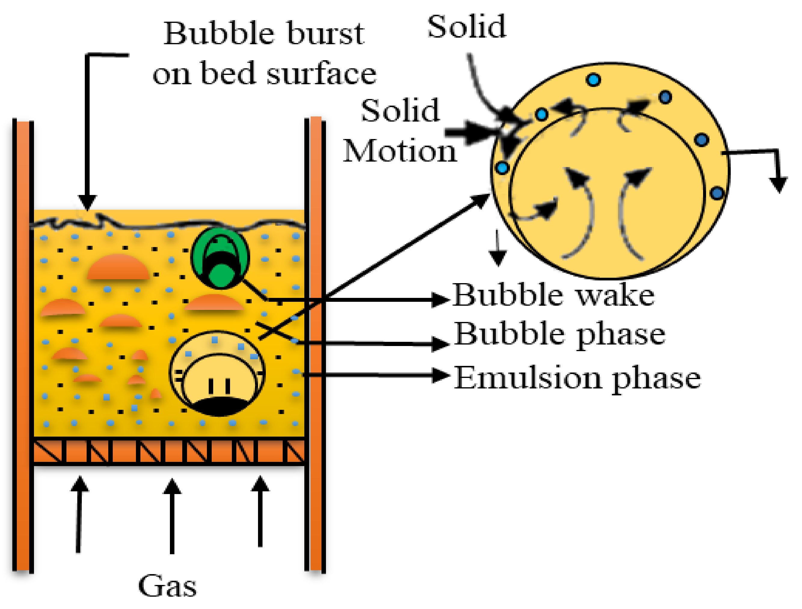
4.1.1. Fast Pyrolysis of Biomass via Bubbling Fluidized-Bed Reactor

Fluidization is a phenomenon in which the fine solids are transformed into a fluid-like state through contact with a gas or liquid. The upward fluid drag on the solid particles by gas is responsible for the fluidization. The particles in the fluidized bed are present in a semi-suspended state. If the gas flow rate through the fixed bed is increased, the pressure drops due to the fluid drag continue to rise. This phenomenon continues until gas velocity maintains a critical value known as the minimum fluidization velocity. At this stage, the fixed bed transforms to a fluidized bed when the fluid drag is equal to the particle weight [113]. Figure 3 shows a typical bubbling fluidized-bed reactor. Bubbles are made at the openings everywhere that the fluidizing gas enters the bed. They are formed because the velocity at the interface of the bed just above the hole represents the gas input rate in surplus of what can pass through the interstices with a frictional resistance less than the bed weight. Hence, the layers of solids above the holes are pushed aside until they make a void through whose porous surface the gas can enter at the incipient fluidization velocity [114].
The advantages of bubbling fluidized-bed reactors include uniform mixing, uniform temperature distribution, and operation in the continuous state [116]. The use of bubbling fluidized-bed reactors for accomplishing the fast pyrolysis of biomass has been reported by numerous researchers [117].
Zhang et al. [118] reported the outcome of crucial operation factors in the fast pyrolysis of biomass (corncob). The pyrolysis was performed in a bubbling fluidized-bed reactor with and without the addition of catalysts. The effective operation parameters were the reaction temperature, gas flow rate, pyrolysis bed height, and the size of biomass feedstock. The catalyst used to alter the results for the investigation on the final products was the HZSM-5 zeolite catalyst. The results suggested that the maximum liquid yield was 56.8 wt.%. The optimal operating parameters identified were a pyrolysis operating temperature of 550 °C, gas flow rate of 3.4 L/min, 0.1 m static bed height, and a particle size of 0.1 to 0.2 cm. The result also shows that the amounts of incondensable gas, coke, and water increase with the addition of a catalyst to fast pyrolysis technology carried out in a bubbling fluidized bed reactor, while the amounts of liquid and char decrease. Dong et al. [119] analyzed the fast pyrolysis of biomass numerically in a fluidized bed reactor. The process was a three-fluid model. In this process, multi-step kinetics was used for biomass thermal decomposition. The hydrodynamics of the fluidized beds with various superficial velocities of fluidizing gases were examined. The results predicted that the superficial velocities should be aimed at carefully. The accuracy of this depends on balancing the char removal efficiency and biomass-heating rate. The presented model system also showed that the heat-penetration model is effective in describing the intra-particle heat transfer. This is validated by the consistency between the simulated and experimental results.

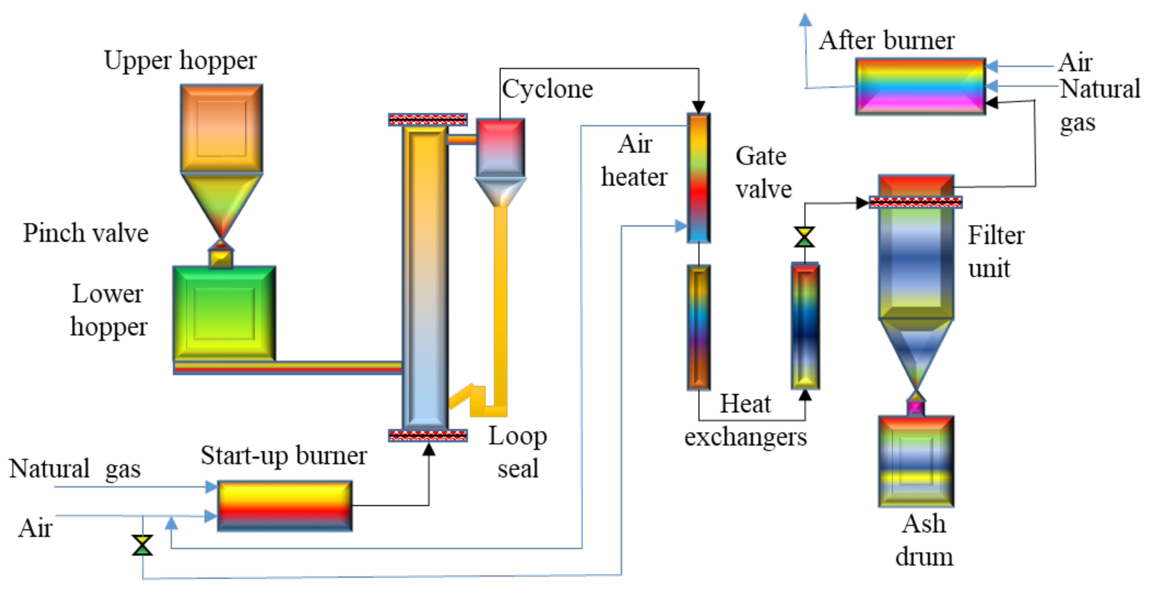
4.1.2. Fast Pyrolysis of Biomass via Circulating Fluidized-Bed Reactor

The circulating fluidized bed reactor has many distinctive properties that make it different from several gas–solid reactors. Hence, it is promising for a wide range of reactions. In an actual circulating fluidized bed, the reactor does not contain any bed and does not have any separate upper surface. On the other hand, it is intermediate in density between the dense fluidization phase and light pneumatic conveying [120]. Circulating fluidized-bed reactors have selection superiority over many other technologies, such as fixed-bed reactors, entrained flow reactors, dense phase fluidized beds, and rotary kilns used in the chemical process industry [121]. The most important features of circulating fluidized-bed reactors that distinguish them from other reactor configurations include internal recycling of huge bulk particles reaching the top of the vessel back to its bottom, a good void range, and no distinct upper bed surface in the column [122]. Figure 4 presents a typical circulating fluidized-bed reactor.
Cao et al. [94] reported bio-oil production in a fast pyrolysis process in an internally circulating fluidized bed. The biomass materials used in this study were sewage sludge, pig dung, and wood chips. The pyrolysis was performed at an optimal temperature of 500 °C. The reported bio-oil yields from sewage sludge, pig dung, and wood chips were 45.2%, 44.4%, and 39.7%, respectively. The elemental characterization of the product shows that the bio-oil from sewage sludge contains more aliphatic species. In contrast, the bio-oil produced from pig dung has a high carbon content, and hence a high heating value. The bio-oil produced from the wood chips is not preferable to use as a fuel because it has high oxygen content, low hydrogen to carbon ratio, and less heating value. Xianwen et al. [124] developed an integrated method for the fast pyrolysis of a biomass material with a circulating fluidized bed reactor. The circulating bed reactor can be modeled and distinguished as two separate zones. These zones represent the pyrolysis (primary reaction zone) and the second reaction zone. Various process parameters, such as the bed temperate, particle size of biomass, and position of the feeder were analyzed. Wood powder was used as the biomass material for pyrolysis. The different compositions and proportions of pyrolysis gas and bio-oil can be seen in the context of the process parameters. The results suggest that the high temperature and prolonged residence time give less bio-oil and leads to secondary reactions. The lower heating rates contribute to more carbonization and minimize liquid production.

4.1.3. Fast Pyrolysis of Biomass via Fixed-Bed Reactors

Fixed-bed reactors are the most common type of reactors used in the process industry. They come mostly in circular cylindrical shapes, even though they are available in all sizes and various other dimensions. Fixed-bed reactors are most commonly filled with solid catalysts [125]. The feed enters from one side, and the product is obtained from the other. The catalyst pellets are fixed at a selected section and do not move against a reference section. Principally, the main chemical reactions occur inside the catalyst [126]. Catalyst recovery and recycling are some of the major criteria for the economy of the fixed-bed reactor and have a major influence on its selection. These reactors are the most important reactors for the large-scale production of chemicals and intermediates. In recent years, they have been used intensively to treat toxic and harmful substances [127].
Amir et al. [128] examined the fast pyrolysis of biomass using the fixed-bed drop-type pyrolyzer. Under the inert conditions, rubberwood sawdust (RWS) and meranti wood sawdust (MWS) were analyzed at various pyrolysis-operating temperatures. The product yield was analyzed for 450 to 650 °C with 50 °C increments in temperature. The same maximum amount of bio-oil was produced from both biomass materials (RWS and MWS) but at different temperatures. Temperatures of 550 and 600 °C were the most suitable for the maximum yield (33 wt.%) from RWS and MWS, respectively. The second part of the research involved the analysis of pyrolysis products obtained from the maximum pyrolysis temperature. The results revealed a high percentage of oxygen and hydrogen in the bio-oil, indicating a high water content.
The presence of a high moisture content in the bio-oil reduced its heating value. The major constituents of non-condensable gases in this research were CO and CO2. Ly et al. [129] examined the pyrolysis of saccharina japonica algae to produce various products, mainly bio-oil in a fixed-bed reactor. Saccharina japonica is a type of macroalgae that has been cultivated in the Republic of Korea in large quantities for renewable energy production. In this experimental study, various sweeping-gas flow rates (100 mL/min, 300 mL/min, and 500 mL/min) and different pyrolysis temperatures (350 to 550 °C) were investigated to obtain bio-oil, gas, and char. As the pyrolysis temperature was increased, the amount of bio-oil decreased, and the gas yield increased for saccharina japonica. The maximum amount of bio-oil (approximately 41 wt.%) was achieved at a pyrolysis temperature of 350 °C and a sweeping flow rate of 300 mL/min. The gas product included CO. CO2, H2, and other hydrocarbons. The biochar contained a high carbonaceous content. Therefore, it is used as a pollution-free solid fuel with a high heating value that can be used to produce activated carbon and other chemicals.

4.1.4. Fast Pyrolysis of Biomass via Ablative Reactor

Ablative reactors are designed to carry out ablative pyrolysis, which is a type of fast pyrolysis. The fundamental principle is the mechanism of heat received by the reacting biomass particles. It is categorized by the dominant mode of heat transfer, which is conduction to the biomass particles. The conditions for ablative pyrolysis are as follows: (a) high relative motion and (b) high contact pressure between the biomass material and heat transfer contact surface. These two combined effects of high contact pressure and relative velocity are responsible for the high ablation rates in the fast pyrolysis of biomass via ablative reactors [130]. Fast pyrolysis through an ablative reactor offers many advantages over conventional fast pyrolysis. The most common of these benefits include (i) a considerably smaller reactor volume, (ii) lower capital costs due to the minimized use of inert gas, (iii) no requirement for recycling gas, (iv) large biomass feedstock can be used directly (up to 50 mm), (v) reduced feed preparation costs, (vi) it can be easily modified for production of renewable products, (vii) high specific throughputs, and (viii) lower operating costs [131].
Luo et al. [132] reported the of whole wood chips and rods in a novel ablative reactor. The biomass material used in the research work was dry wood. The study also included the pyrolysis liquid collection system, which could indicate the influence of key process parameters. The designed system explained the relationships between the parameters and product quality. The model was developed to account for the ablative pyrolysis process. The conversion of whole wood and wood rods directly to pyrolysis products saves considerable amounts of money spent on grinding, chipping, and shredding wood to smaller sizes. These unit operations account for approximately 7–9% of the total process cost. The research presented the development and testing of a laboratory-scale ablative pyrolysis reactor converting wood chips and wood rods into a high yield of bio-oil (60 wt.%). Moreover, the amount and composition of bio-oil from the ablative reactor resembled a similar product from a fluidized bed reactor imparting wood chips smaller than 1 mm. On the other hand, these have a slightly lower heating value (LHV) and higher water content than the same biomass material (<1 mm in size) in a fluidized bed reactor. The study can help develop small-scale mobile and portable ablative pyrolysis reactors for the efficient disposal and conversion of forest residues. Peacocke and Brodgwater [133] presented a novel design for the ablative fast pyrolysis reactor. Figure 5 presents a typical ablative pyrolysis reactor.

4.1.5. Fast Pyrolysis of Biomass via Entrained Flow Reactor

Entrained flow reactors, commonly known as drop tube furnaces, have been used for decades to convert coal and biomass materials into energy fuels. Principally, it consists of an externally heated vertical tube inside which hot laminar gas flow is passed to decompose the coal/biomass material thermally [135]. These reactors are usually operated isothermally, and the gas flow is heated to the reactor wall temperature. The entrained flow reactor allows the coal/biomass to encounter the same heating rate, temperature, and residence time inside the reactor tube. The entrained flow reactor has the following three characteristics for the maximum conversion efficiency: (a) short residence time of biomass in the reactor (few seconds), (b) very small feedstock size (100 µm), and (c) very high temperature (>1000 °C) [136]. The reactor can be divided into two main types: slagging and non-slagging entrained flow reactors. In the slagging entrained flow reactor, the ash leaves the bottom of the reactor as a liquid slag by melting with the reactor walls. In the latter, non-slagging entrained flow reactor, there is no problem with slag, and it is suitable for biomass with a smaller ash content. The entrained flow reactor can be used for a wide range of biomass at high pressures and temperatures [137]. Figure 6 presents the simplified type of an entrained flow reactor.
Dupont et al. [139] performed the experiments in an entrained flow reactor. The study was performed to understand the kinetic processes involved in biomass pyrolysis at instantaneous heating rates (>500 K/s) and high temperatures. The temperature ranged from 1073 to 1273 K. The effects of various parameters, such as the particle size, operating temperature, presence of steam in a gas atmosphere, and residence time, were studied for conversion and selectivity. The biomass particle size was the most important factor among all these influential parameters. Pyrolysis took more than 0.5 s for a particle size of 1.1 mm and less than 0.5 s for 0.4 mm particles. The gas produced from the biomass pyrolysis through the entrained flow reactor was 70 wt.%. The amount of initial carbon was 40% as CO and 5% as CO2. An equal distribution of hydrogen in H2, H2O, CH4, C2H2, and C2H4, was observed. Bitowft et al. [140] performed the fast pyrolysis of sawdust in an entrained flow reactor. The examinations of the pyrolysis products were made over a temperature range of 1000 to 1400 °C. The particle residence time was maintained from 0.56 to 1.0 s, and the particle size fractions ranged from 250 to 630 µm. An intermediate calorific value gas was produced during the investigation. The results show that more than 87% of the biomass fed into the system was accounted for in the product streams. The reported cold gas efficiency for all the experiments exceeded 70% with an average value of 79%. Higher temperatures resulted in no tar formation for this experimental setup.

4.1.6. Catalytic Fast Pyrolysis of Biomass

The conversion of lignocellulosic materials into liquid fuels is in high demand because of the increased prices of fossil fuels, national security considerations, and potential climate disasters. Table 5 lists the comparative studies of fast pyrolysis using different types of reactors and approaches.
Various technologies are under consideration, among which fast pyrolysis is used frequently for bio-oil production [152]. Bio-oil comprises nearly 70% of the energy of the biomass feedstock. On the other hand, certain flaws in the bio-oil properties restrict its commercialization compared to crude oil-based liquid fuels. These properties include (i) lower calorific value, (ii) reduced volatility, (iii) undesired acidity, (iv) instability, and (v) incompatibility with other petroleum fuels [153]. These undesirable properties of bio-oil from lignocellulosic biomass materials are caused by the presence of oxygenated organic compounds, which are dominant in its chemical composition. The removal of oxygen is necessary to broaden the acceptance of bio-oil and to enhance its economic acceptance. Therefore, catalytic pyrolysis using various commercially available catalysts, such as zeolites, to produce aromatic range fuels is the process used to accomplish this goal in pyrolysis technology [154]. Chen et al. [155] examined the fast catalytic pyrolysis of biomass material using the ZSM5 catalyst. They reported that carbon monoxide, carbon dioxide, coke, and hydrocarbons were the main products obtained from pyrolysis. The main goal was to increase the hydrogen content in the hydrocarbons and eliminate the excess oxygen from the biomass. Therefore, the researchers reported the effective hydrogen to oxygen ratio as an outcome of this study. The mathematical form of this hydrogen to oxygen ratio was H/C = H-2O-3N-2S/C. The relation helps us understand the chemistry involved in converting oxygenates during the catalytic conversion of biomass. On the other hand, the H/C ratio for the biomass-derived oxygenates was less than the H/C ratio of petroleum-derived feedstock.
Jia et al. [156] performed the catalytic fast pyrolysis of oak in a micro fluidized-bed reactor. The two zeolites, i.e., microporous and hierarchical, were used at 500 °C and different biomass/catalyst ratios. SPI-MS was used to monitor the formation of the pyrolysis products during the stepwise injection of wood particles within the micro fluidized-bed reactor. The selectivity in the targeted mono-aromatic compounds was doubled after the desilication of zeolite. TEM-EDX was used for the characterization of coked zeolites. Three different types of coke were verified: (a) the coke trapped inside the catalyst pores, (b) the coke formed on the outer surface of the crystals, and (c) the coke originators left in the mesoporous. The evacuation of the catalytic products was promoted by the mesopores, which increased the selectivity in mono-aromatic hydrocarbons. The results also showed that the desilicated zeolite imparts more selectivity to mono-aromatics and stability upon the coke deposit than the functioning of microporous zeolite. Wang et al. [157] performed the reactive fast catalytic pyrolysis of biomass material to produce high-quality bio-crude. Reactive catalytic fast pyrolysis was performed under atmospheric pressure hydrogen. The studies were made in a laboratory-scale fluidized-bed reactor while modifying the multiple process parameters. The key parameters were the operating temperature, hydrogen concentration, and catalyst. The results showed that the quality and yield of bio-crude were enhanced in hydrogen in reactive catalytic fast pyrolysis. A molybdenum-type catalyst was reported to be the most effective in the hydrodeoxygenation phenomenon. Hydrodeoxygenation converts the biomass pyrolysis vapors to produce a hydrocarbon-rich bio-crude with a minimum oxygen content (< 10 wt.%). The moderate pyrolysis temperature of 450 °C and higher hydrogen concentration supports the increased bio-crude yields and quality.

4.2. Slow Pyrolysis Process

Biochar, also known as charcoal, is the main product of the slow pyrolysis process. Slower heating rates are used in the slow pyrolysis of biomass materials, which is approximately between 0.1–0.8 °C/s [158]. Compared to the fast pyrolysis process, the residence time in the slow pyrolysis process is kept longer. The approximate residence time in most pyrolysis reactors is 5–30 min or sometimes 25–35 h [159]. The temperature was between 300 °C to 550 °C [160]. The biomass feedstock, operating temperature, heating rate, and pyrolysis environment influence the biochar and bio-oil yield [161]. The pyrolysis environment accounts for whether pyrolysis occurs in the presence of N2 or CO2 and even in altered-bed materials [162]. The woody biomass contains fewer minerals than the herbaceous biomass and produces extra products. The increase in the pyrolysis temperature decreases the biochar yield. This is because, at elevated temperatures, organic materials are combusted along with the destruction of cellulose and hemicellulose materials [163]. Several technologies are used to accomplish a fast pyrolysis process:
Slow Pyrolysis of Biomass via Fixed-Bed Reactor,
Slow Pyrolysis of Biomass via Augers Reactor,
Slow Pyrolysis of Biomass via Rotary-Kiln Reactor, and
Catalytic Slow Pyrolysis of Biomass

4.2.1. Slow Pyrolysis of Biomass via Fixed-Bed Reactor

As discussed in Section 4.1.3, fixed-bed reactors are used widely in many process applications. These reactors have much importance in biomass pyrolysis because they offer many unique properties. Therefore, they are used frequently by researchers and industries for the slow pyrolysis of biomass, in which the aim is to obtain a solid product char. The fixed beds are made from a solid catalyst to increase the product yield and modify or alter the process conditions. Therefore, their application in the slow pyrolysis of biomass has great importance. Many researchers have used fixed-bed reactors for the slow pyrolysis of biomass.
Kabir et al. [164] examined the slow pyrolysis of oil palm mesocarp fiber (OPFM) and palm frond (PF) and compared the obtained results. A fixed-bed reactor was used because of its simple design. The pyrolysis process was conducted at different N2 flow rates and temperatures to obtain the preferred products, which are bio-oil and bio-char. The products obtained from the slow pyrolysis process (heating rate of 10 °C/min) at a flow rate of 200 mL/min and temperatures ranging from 500 °C to 600 °C showed reduced gas production and a maximum yield of OPMF oil and PF oil. The proximate analysis of pyrolysis provided low ash, high HHV, and a high amount of fixed carbon, which is desirable compared to other biomass feedstocks. Ultimate analysis resulted in low oxygen to carbon ratios and low nitrogen and sulfur contents (negligible NOx and SOx emissions), highlighting these bio-oils as an excellent renewable source biofuel. Using gas chromatography-mass spectrometry (GC-MC), these bio-oils contained mixtures of oxygenated compounds and aromatic compounds, which are important for better fuel properties.
Wang et al. [165] examined the slow pyrolysis of pinewood using a fixed-bed reactor by gas sweeping to minimize the secondary reactions. The yield and characteristics for different biomasses differ. The characteristics of pinewood were clarified by determining the yields of gas, tar, and char. The experiment was performed at temperatures from 200 to 700 °C. The four major incondensable gases formed were H2, CO, CH4, and a smaller amount of CO2. Thirty-eight liquid compounds were obtained from the pyrolysis process, including saccharide, carboxylic acid, furan, ketone, and aldehyde, resulting from dehydration and decarboxylation. While cellulose maintained its actual structure, it decomposed at 300 to 450 °C, providing large amounts of liquids and gaseous products. The residues of this process decomposed at temperatures from 450 to 700 °C to form several types of gases.

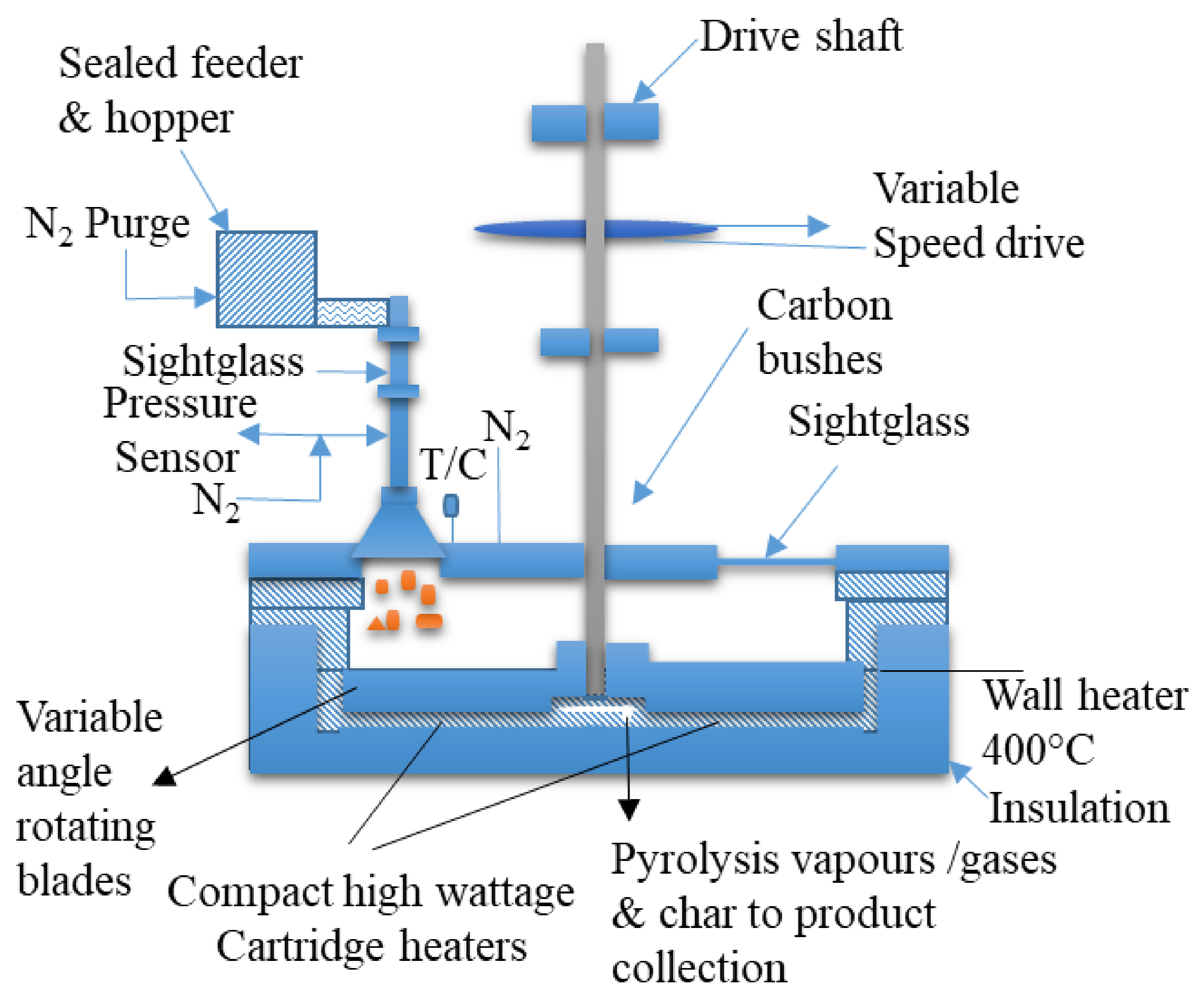
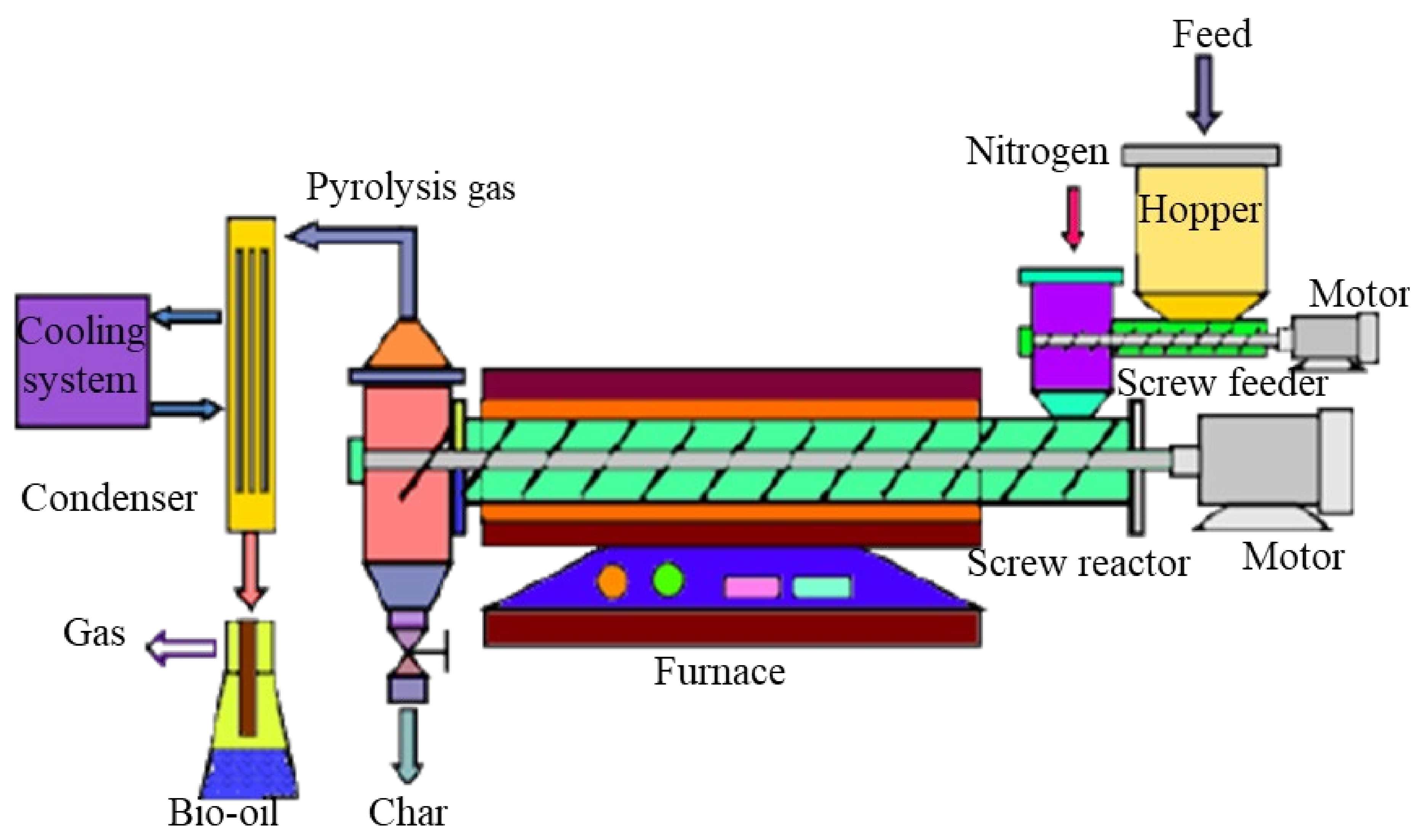
4.2.2. Slow Pyrolysis of Biomass Using the Augers Reactor

Small- and medium-sized industries have become increasingly interested in the use of auger reactors for the pyrolysis of lignocellulosic biomass materials. The simplicity in its construction and operation makes it popular among the other technologies [166]. The operating mechanism of the auger reactor involves the continuous feeding of the biomass material into the inlet of a screw feeder, which supplies the material to the heating zone of the pyrolysis chamber along the axis of its rotation. The system could have a single or twin-screw feeder depending on several factors, such as the feeding rate and required feedstock particle size for the heating zone. Biochar is received at the bottom of the reactor after the decomposition of biomass materials. Pyrolysis gases and other volatilities also leave the reactor. The system has the following advantages: (i) simple operation, (ii) no requirement of carrier gas, and iii) low energy consumption. One major advantage is the controlled residence time of biomass in the heating zone by adjusting the rotational speed of the screw feeder. A typical yield of bio-oil from the auger reactor is in the range of 40–60% of the feedstock. The yield depends mainly on the operating conditions and is generally less than that obtained in fluidized-bed reactors. Figure 7 shows a simplified auger reactor used for biomass pyrolysis [167].
Manuel et al. [169] reported the production and characterization of fuel properties for biomass-based bio-oil and bio-diesel blends using slow pyrolysis auger reactors. The synthesis of pyrolysis-based bio-oil has been of particular interest using the simple system. The biomass material used for this experimental study was pine chips and pine pallets. The preparation of bio-oil and the fuel properties of the bio-oil/biodiesel blends are reported. The liquids condensed from pyrolysis consist of two phases: (a) an aqueous phase and (b) a dense, oily phase (bottom phase). Another additional phase called the polar phase is formed after removing water from the aqueous phase. The oily bottom phase has an affinity with biodiesel, making it soluble. The factors that account for the poor fuel properties are the presence of water and low-molecular compounds. These factors are also responsible for the lower solubility of bio-oil with biodiesel. Important fuel properties on which bio-oil/bio-diesel blends can be assessed are pH, viscosity, density, heating value, and water content.
Shi-Shen Liaw et al. [170] examined the operating temperature effects on the yield of pyrolysis liquid products. The biomass material used in their study was Douglas firewood, and they applied slow pyrolysis using the augers reactor technology. The operating temperature was 200 to 600 °C for the experimental tests. The bio-oil yields gained (59 wt.%) from the pyrolysis through the auger reactor were similar to those of fluidized bed reactors. The maximum bio-oil yield was achieved at a reaction temperature of 500 °C. The mass percentage of the water yield from the auger reactor was compared with the other biomass materials processed in fluidized bed reactors. They confirmed that the pyrolysis of biomass in an auger reactor could produce a good yield of bio-oil and bio-char. Slower heating rates and secondary reactions, however, affect the composition of the pyrolysis products.

4.2.3. Slow Pyrolysis of Biomass via Rotary Kiln Reactor

The pyrolysis of biomass in a rotary kiln finds use as an intermediary stage in multistage gasification and as a process to produce biochar. Rotary kilns are the favored reactor structure for the thermal treatment of particulate solids. Substantial research has been conducted to determine their performance for the utilization of lignocellulosic biomass materials [171]. Rotary kiln pyrolyzers are preferable over many other reactors because of their many various unique advantages. The distinctive properties of products from biomass materials can be obtained by the slow rotation of the inclined rotary kiln pyrolyzers. The residence time of the feedstock in the kiln chamber can be controlled, and appropriate adjustments for optimal operation can be made. These kilns also allow the use of biomass with a wide range of sizes, shapes, and calorific values, which can be fed continuously or in batches [172]. These reactors are also less sensitive to the fuel nature. Hence, they can accommodate an enormous diversity of biomass materials without any pre-treatment [173]. Figure 8 presents the experimental setup of a laboratory-scale rotary kiln used in biomass pyrolysis.
Fantozzi et al. [175] examined the production of syngas and char from biomass and waste by using a slow pyrolysis process in a rotary kiln. They used a laboratory-scale designed electrical rotary kiln. The gas cleaning system consisted of a wet scrubber that removes the tar and the dust particles. There is also a monitored combustion chamber for an analysis of the LHV of the producer gas. They reported the effects of the pyrolysis temperature and residence time on syngas production, char yields, and amount of tar. The study primarily developed the relationship between theoretical and experimental calculations. The association developed in their research is helpful for determining and designing the working envelope of a rotary kiln as a function of the feedstock bulk density and moisture content.
Colin et al. [176] assessed the rotary kiln pyrolysis of biomass material. The biomass material in this study was wood chips. The modeling and simulation of the system were performed to forecast the effects of various operating parameters on the product yields. The target of the study was to analyze the flow pattern of the biomass material during the pyrolysis process, which is also an important parameter for rotary kilns and influences the product formation. Two other important factors are the mean residence time and the bed depth profile. Both parameters were calculated using the standard Saeman model. The mean residence time for the biomass materials was determined using residence time distribution (RTD) experiments. For these experiments, biomass materials (raw and torrefied wood chips) were used in a powdered form inside the rotary pyrolysis kiln. The mean residence time of the rotary pyrolysis system correlated with many process parameters, such as the inclined slope of the kiln, rotational speed for pyrolysis, biomass inlet feeding rate, and flow rate. The installation of a small plug flow was emphasized if some segregation phenomena were observed. The Saeman model was adjusted to forecast precisely the load profile and the mean residence time of particles with parallelepiped form. The inconsistency amid the experimental and calculated results was minimized from 25% to 5% for the mean residence time and mean solid hold-up.

4.2.4. Catalytic Slow Pyrolysis of Biomass

The presence of a catalyst in the fast biomass pyrolysis aims to increase the bio-oil yield and alter its composition by decreasing the oxygenated content in its chemical composition. The catalytic slow pyrolysis of biomass was performed to increase the biochar yield, which is the primary product of slow pyrolysis. Therefore, the use of catalysts in slow pyrolysis is important for controlling the bio-char quality and composition. Catalysts are employed for several reasons during the process, including (i) lower pyrolysis temperature, (ii) higher chemical and physical stability, and (iii) higher yield of target components. The technology of catalytic slow pyrolysis of biomass is under consideration for further research by the scientific community and has been implemented in industries for biochar production. Catalysts are known to be effective bio-oil upgraders because they exhibit high resistance to deactivation due to their uniform pore structure and suitable acidity. Several studies have been reported that catalysts play vital roles in the manufacture of good quality recovery of products [177]. Catalytic pyrolysis of plastic is a promising technology and requires specific reactor configurations and operating conditions. Rashid Miandad et al. [178] performed the catalytic pyrolysis of different types of plastics wastes (PS, PE, PP, and PET) as single or mixed in different ratios, in the presence of modified natural zeolite (NZ) catalysts, in a small pilot scale pyrolysis reactor. The experiments were carried out in a small pilot-scale pyrolysis reactor at 450 °C, using a heating rate of 10 °C/min and reaction time of 75 min. The catalytic pyrolysis of PS produced the highest liquid oil (70 and 60%) compared to PP (40 and 54%) and PE (40 and 42%).
Du et al. [179] performed the slow catalytic pyrolysis of biomass and identified the multiple routes and mechanisms of char and coke production. These two products cannot be considered identical because they inhabit different sites on the surface of the catalyst and respond separately to the deactivation phenomenon of the catalysts. The catalyst used for this research was ZSM-5, which was examined to determine the char and tar yields from biomass and the level of catalyst deactivation from pine sawdust, glucose, and cellulose as biomass feedstock in these experiments. The composition, oxidation reactivity, catalyst surface area, pore size distribution changes, and bonding groups were analyzed for the char and tar produced by the slow thermal and catalytic pyrolysis of biomass material. According to their study, the catalyst surface was covered with char in the macropores. The coke accumulates inside the zeolite micropores, which were facilitated by hydrogen transfer and pyrolysis addition reactions. The influence of the catalyst on glucose and pine slow catalytic pyrolysis is related to that on cellulose slow catalytic pyrolysis due to macropore blocking by char formation. Russell et al. [180] utilized the slow catalytic biomass pyrolysis process to increase the charcoal yield and the synthesis of low-molecular oils. Significant research work to reduce CO2 production and enhance the product yield and quality from biomass pyrolysis is in progress. There is the probable use of the catalytic slow pyrolysis process to produce charcoal, which can be used for cooking and soil remediation. Aluminosilicate catalysts had high potential to make this process more efficient and increase the yield. They concluded that this catalytic process could be useful for slow pyrolysis using low-cost aluminosilicate minerals, particularly bentonite clay. The study also reported the increase in charcoal yield with the addition of bentonite clay (60 wt.%). At 700 °C with a 60% clay filling, the charcoal yield improved 16 wt.% (dry ash-free basis), but at the same time, 19% of additional gas was generated at the expense of 35% of the oil from raw pine pyrolysis. Table 6 lists the comparative studies of slow pyrolysis using different reactors and approaches.

5. Advanced Pyrolysis Processes

In addition to the two main classes of biomass pyrolysis technologies (slow pyrolysis and fast pyrolysis), there is another category of pyrolysis that is referred to as advanced pyrolysis. These processes lie in between the operating domains of both fast and slow pyrolysis and have benefits that are sometimes not possible with a single category of pyrolysis technology. Hence, a wide range of categories is available for these advanced biomass pyrolysis processes. The most developed technologies among these biomass pyrolysis processes are as follows:
1.
Vacuum pyrolysis of biomass,
2.
Microwave pyrolysis of biomass,
3.
Flash pyrolysis of biomass,
4.
Biomass pyrolysis via plasma technology, and
5.
Biomass pyrolysis via solar energy.

5.1. Vacuum Pyrolysis of Biomass

Vacuum moving-bed reactors are used for the vacuum pyrolysis of biomass materials. It is not a type of fast pyrolysis, but the aim is the enhance the bio-oil yield. The working principle suggests that the introduction of vacuum conditions reduces the residence time of the pyrolysis vapors. This hinders the occurrence of secondary vapor-phase reactions. Compared to other pyrolysis techniques, vacuum pyrolysis can handle large biomass particles because of less heat transfer demand. The inert carrier gas medium is also not needed in this pyrolysis technology [191]. The concept is to employ the conditions of slow and fast pyrolysis simultaneously. Therefore, the coarse biomass particles are heated slowly but at temperatures higher than in slow pyrolysis. The pyrolysis gases are removed very quickly from the heating zone with the application of reduced pressure. Vacuum pyrolysis of biomass requires high investment and maintenance costs because a special control system is needed to feed the biomass and discharge gases while maintaining the vacuum conditions [192]. Despite this flaw, it has the following advantages: (i) good product quality, (ii) liquid product condensation, (iii) particle size, (iv) ease in component extraction, and (v) very little or no char formation [65]. Figure 9 shows a laboratory-scale vacuum pyrolysis reactor.
Garcia et al. [194] investigated the yield and properties of pyrolysis products. The technology used for the study was the vacuum pyrolysis of biomass materials. The focus was on analyzing the properties of bio-oil. Softwood bark (SWBR) and hardwood rich in fiber (HWRF) were used as the biomass feedstock in vacuum pyrolysis. The thermogravimetric technique was used to analyze the lignin, cellulose, and hemicellulose content. The results showed that the SWBR biomass holds 14.8 wt.% of extractives and an accumulative lignin content of 44.8 wt.%, while the second studied biomass HWRF contains 40.1 wt.% of cellulose and 27.8 wt.% of hemicellulose material. Vacuum pyrolysis produces the immiscible phases for bio-oil produced, which is later separated by decantation. The upper oil layer is comprised of 16 wt.% SWBR and incorporates higher than 50 wt.% of the extractive-routed compound mixture. HWRF presents a portion of 1.3 wt.% of the entire initial oil, which was a waxy phase consisting of paraffin, sterols, and fatty acid methyl esters. On the other hand, the bottommost layer from both the biomasses was identical to the bio-oils gained from bark-free wood. Xu et al. [195] performed the vacuum pyrolysis of the biomass using the catalyst. The Mo-Ni/Al2O3 catalyst was used to upgrade the bio-oil. The biomass material used was pine sawdust, and the bio-oil was produced under the optimal operating parameters. A various set of nickel-based catalysts were made, and their catalytic activities were monitored. The assessment was carried out by upgrading the glacial acetic acid (model compound). The modified Mo-10 Ni/Al2O3 catalyst was used to upgrade the pyrolysis crude bio-oil. The pH of the crude oil increased from 2.16 to 2.84, and the water content increased from 46.2 wt.% to 58.99 wt.% after upgrading. The hydrogen content increased from 6.61 wt.% to 6.93 wt.% and the dynamic viscosity decreased slightly. The GC-MS spectrometry outcomes revealed a three-fold increase in the ester compounds after the upgradation process. Recently, Ying et al. [196] used the microwave vacuum pyrolysis technique to convert cassava stem into biochar. The morphology of the biochar has abundant pores, indicating it to be a good catalyst and a surface for the adsorbance of heavy metals in wastewater treatment. For conventional use as an energy fuel, it had a calorific value between 19 and 21 MJ/kg. That study confirmed that low-grade cassava stem could be converted to energy fuel and be used as a catalyst source using microwaves.

5.2. Microwave Pyrolysis of Biomass

The microwave pyrolysis of biomass has been under consideration in the scientific community for a few decades, and progressive research is being carried out. Microwave pyrolysis technology differs in the principle of operation compared to other well-established biomass pyrolysis techniques because the heating of biomass material is intrinsic, not extrinsic [197]. A very high heat source is not required to decompose the biomass material. The biomass material with a high dielectric constant or loss factor is preferable for microwave pyrolysis. Water is a good example of a component feasible to be subjected to microwave pyrolysis. When a biomass material with a high moisture content is pyrolyzed by microwave heating, the water is first driven off rapidly. The remaining biomass retains heat and starts forming char [198]. Microwave pyrolysis is electrically conductive, and eddy currents are formed that establish prompt heating. Hence, controlling the microwave operating conditions for the required results is the main task. The microwaves can penetrate only 1–2 cm. Therefore, a microwave reactor offers interesting scale-up challenges. An environment is formed in microwave pyrolysis due to the uniform heating of the biomass material, leading to learning and exploring the fundamentals of the pyrolysis mechanism. This also helps us to understand the effects of the thermal gradient in a pyrolysis particle and the secondary reactions that occur during biomass pyrolysis. Figure 10 presents the process flow diagram for the microwave pyrolysis of biomass material [65].
Bu et al. [199] reported the microwave pyrolysis of biomass using a catalyst and consuming activated carbon (AC). The effects of the catalytic microwave pyrolysis on the production of phenol and phenolics were investigated. Various pyrolysis-operating parameters were also analyzed to report their consequences on the yield of products. Pyrolysis bio-oil with a high concentration of phenol (39%) and phenolics (70%) was produced. The better results were linked with the rapid dissociation of lignin due to the AC. Therefore, these results were better than those performed in the absence of AC. Zinc powder was used as a catalyst medium, and formic acid or ethanol was utilized as the reaction medium. A high concentration of esters (43%) was obtained in the upgraded bio-oil because of the catalyst. The characterization performed by GC-MS showed that the maximum esters developed were long-chain fatty acid esters. The study results suggest that after removing the oxygenates, the high content of esters and phenols produced can be used instead of traditional fossil fuels. Refining can lead to their use in chemical and process industries for organic synthesis.
Robinson et al. [201] examined the microwave pyrolysis of biomass. The biomass material used for this study was wood pellets. The technology involved a single-mode microwave cavity. The dielectric properties of the wood pellets were calculated up to 700 °C. The water acted alone as the microwave absorbing phase in the wood pallets as biomass in microwave pyrolysis below 600 °C. The research presents a new aspect of using the microwave pyrolysis of biomass without using carbon-rich dopants. Water formed below 600 °C alone is sufficient to encourage the pyrolysis of wood pallets. Their research also highlighted many mechanisms that connect the power density inside the pyrolyzed material. The pyrolysis products, i.e., bio-oil and pyrolysis gas, were dependent on the heating rates, operating temperature, and power density. The wood pellets used in the research work had a minimum threshold value of 5.0 × 10⁸ W/m2. Microwave pyrolysis will not proceed if the value is less than this standard value. This research has great worth in understanding the basic mechanisms of the microwave pyrolysis of biomass. In a recent study, Ren et al. [202] converted horse manure to biochar by microwave pyrolysis. The quality of biochar was affected by temperature, catalyst loading, and carrier gas flow rate. The biochar had a calorific value of 35 MJ/kg and a high surface to volume ratio. Biochar with a high surface area is a good candidate for a bio-adsorbent and an additive for soil improvement. A microwave pyrolysis temperature of 350–450 °C and catalyst/manure ratio of 1:1 were optimum for this investigation. Synthesis gas at 73.1 vol% with heating value 14.85 MJ/m3 was also obtained.

5.3. Flash Pyrolysis of Biomass

There are certain physical conditions of biomass pyrolysis that have a high impact on the product quality, product composition, and product yield. These parameters are (i) operating temperature, (ii) heating rate, and (iii) residence time. In biomass pyrolysis, more liquid products with less char and gas formation occur if the operating conditions are in the following constraints (a) higher heating rate, i.e., 104 K/s, (b) temperature <650 °C, and (c) rapid quenching. The biomass pyrolysis operated under these conditions is referred to as flash pyrolysis. Higher heating rates with temperatures >650 °C favor the formation of gaseous products, and slow heating rates with the lowest maximum temperature favor the formation of char [203]. The residence time of only a very few seconds or even sometimes less with high temperatures demands a pyrolysis reactor configuration capable of very high heating rates. Most flash pyrolysis studies were carried out in an entrained flow reactor or fluidized-bed reactor [204]. Biomass flash pyrolysis technology is versatile, simpler, and requires a little capital investment. The technology produces bio-oil with a yield of 60–75 wt.% and consists mainly of a complex mixture of oxygenated compounds whose composition depends on the biomass material used and the pyrolysis operating conditions [205]. Figure 11 represents a simplified pictorial of biomass flash pyrolysis. Pokorana et al. [206] reported that municipal wastewater treatment sleds are difficult to manage and expensive problems to solve. Landfill is a common disposal process. Many European countries rely solely on landfill and the dumping of waste materials. Landfill requires considerable space to fulfill the requirements continually. The soil also must be protected against the toxic and hazardous compounds of municipal sludge. Instead of landfill for these wastes, thermal treatment is the most feasible alternative to deal with the issue. The carbon and sulfur emissions caused by combustion need to be controlled to protect the environment. Pyrolysis from a thermochemical route has the potential to solve the severity of this issue. The process of degrading the biomass occurs in an inert atmosphere. Various types of products are achieved, i.e., bio-oil, biochar, and pyrolysis gases. Flash pyrolysis is a technology to enhance the liquid product from the pyrolysis process. The heating rate in flash pyrolysis is very fast, and a dark brown liquid consisting of a composite blend of oxygenated hydrocarbons is formed. Liquid bio-oil production can be stored until its application.
Goyal et al. [20] published an article on biomass pyrolysis to produce excess bio-oil. The flash pyrolysis technology was adopted to enhance the yield of liquid fuel. Fast pyrolysis was performed, allowing the pyrolysis reaction to take place in a few seconds or even less. This research scheme implies the application of flash pyrolysis through the entrained flow reactor and fluidized bed reactor. The pyrolysis in both reactors was carried out at very high heating rates. The size of the cellulose materials ranged from 105–250 µm. Flash hydro-pyrolysis technology was carried out in a hydrogen atmosphere at pressures up to 20 MPa. Another technology is solar flash pyrolysis, in which concentrated solar energy is used to perform flash pyrolysis. Solar energy is collected through solar collectors, solar towers, and dish connectors.
In the latest study published by Matamba et al. [208], flash pyrolysis of a palm kernel shell was performed. The operating temperature and pressures were 600–900 °C and 0.1–4.0 MPa, respectively. They examined the effects of pressure in flash pyrolysis for the increased production of the desired product. Increased pressures and temperatures particularly stimulated the formation of polycyclic aromatic hydrocarbons and H2 gas. At lower temperatures and pressures, the bio-oil samples produced were composed primarily of phenolics. Higher temperatures and pressures improved hydrogen transfer to a light gaseous phase. The production of hydrogen peaked at 40.82 g of H2/kg of PKS at 900 °C and 2.0 MPa. They showed that the pyrolysis of biomass at high pressures could be a preferable technique for the polygeneration of hydrogen gas and aromatic hydrocarbons as chemical feedstocks.

5.4. Pyrolysis of Biomass via Plasma Technology

Compared to conventional biomass pyrolysis techniques, plasma pyrolysis technology offers many unique properties. These advantages are possible at low temperatures and slow heating rates [209]. The problems that are associated with conventional biomass pyrolysis, such as low gas yield and high tar amounts, can be eliminated by plasma pyrolysis technology. This is possible because of the fast reaction times, high energy density, and temperature offered by plasma pyrolysis technology [210]. Many plasma pyrolysis applications lie in the destruction of noxious materials because of the high-power energy required for its operation. Therefore, thermal plasma technology for biomass pyrolysis has been less explored due to economic constraints. The temperature obtained in thermal biomass plasma pyrolysis is very high (3000–10,000 K), and much of the energy is radiated and conducted to the surroundings [211]. Many energy species, such as electrons, ions, atoms, free radicals, and activated molecules, are present in the thermally activated plasma. The temperature exceeds 3000 K when thermally activated by an electric arc discharge. When carbonaceous materials, such as biomass or coal, are treated with plasma, they decompose with sudden heating, and volatile components are released. These components are mostly CH4, CO, H2, C2H2, and various light hydrocarbons [212].
Huang et al. [213] examined the plasma pyrolysis process for the production of various products. Two products that were the focus of this research were the pyrolysis syngas (CO + H2) and carbon absorbent. The type of technology implemented in this research work was a radio-frequency plasma reactor. The scope of the study was broadened to different temperatures and pressures (3000–8000 Pa). The power supplied to the plasma reactor ranged from 1600 to 2000 W. The process parameter conditions affected the pyrolysis products. The char amount produced, combustible gas amount, syngas composition, and the quality of char obtained were measured. The maximum syngas yield (66 wt.%) was obtained because of the power supply of 1800 W and pyrolysis operation pressure of 500 Pa. The syngas composition (CO and H2) consists of 76 vol% on a N2-free basis. The solid produced has a large surface area with a high pore volume. This also has many micropores with potential use as activated carbon. Tang et al. [214] published the results of the experiments on the plasma technology pyrolysis reactor. The advanced pyrolysis technology utilized for the research work was the argon/hydrogen plasma pyrolysis reactor. The experimentation was performed on a laboratory-scale reactor. Hydrogen, carbon monoxide, and methane were the combustible pyrolysis gases from this pyrolysis arrangement. The results showed that this technology has a high benefit of carbon conversion into combustible gases. The conversion was 79% for carbon and 72% for oxygen in the gaseous products. The producer gas has high potential applications as syngas. The use of biomass material as an energy resource has many ecological benefits. Therefore, biomass has been given priority over fossil fuels for utilization in plasma pyrolysis reactors.

5.5. Pyrolysis of Biomass via Solar Energy

Solar energy-assisted biomass pyrolysis is an endothermic process of converting the biomass material into an inert atmosphere, which is suitable for its decomposition. The necessary thermal energy is supplied by concentrating solar energy. An optical system assists in redirecting and focusing the solar energy on the biomass pyrolysis reactor. Hence, the required biomass pyrolysis temperatures are achieved by the concentrated solar energy. Three possible mechanisms are developed to transfer solar energy to biomass materials. These methods include (i) passage through the reactor walls, (ii) direct application of solar irradiation of the biomass materials, and (iii) through intermediate heat carrier fluid. The secondary pyrolysis reactions in the gas phase can be minimized or eliminated by irradiating the biomass material directly from solar energy because, in this method, the biomass becomes the hottest part, and the reactor walls remain at a lower temperature [215]. The plasma pyrolysis reactor configuration is shown in Figure 12 [216].
Biomass solar pyrolysis can also be accomplished using thermo-solar systems. This system provides the heating source by redirecting the solar radiation from a large surface to a smaller area. This system has three core components: (a) solar concentrator, (b) solar collector, and (c) supporting structure [217].
Adinberg et al. [218] presented an innovative solar pyrolysis process and experimental apparatus for the thermochemical conversion of biomass into valuable products. The core thematic scheme lies in the distribution of biomass materials into the molten inorganic salt medium. The energy is supplied for pyrolysis through solar energy. The reactions took place in a high-temperature liquid phase by absorption, concentrating, keeping, and relocating the solar energy to the desired operation and application. A tailor-made solar pyrolysis reactor (laboratory-scale) was designed to have the potassium and sodium carbonate salts. The complete kinetics of the solar-assisted fast pyrolysis and the characteristics of the heat transfer mechanisms for the biomass particles were studied in molten salt media. The reaction temperature and heating rate influence the pyrolysis products and yields. The preferable optimal temperature and heating rates were 1073–1188 K and 100 K/s, respectively. The study concluded that the pyrolysis of biomass materials in molten salt phases and the use of solar energy for its operation is a feasible, economical, and continuous way of producing valuable solid and liquid pyrolysis fuels. These results were validated through the commercial-scale solar pyrolysis biomass reactor. Zeng et al. [219] exploited the laboratory-scale pyrolysis solar reactor to examine the effects of operating temperature and the rate of heating for beech wood as the biomass material. These effects were studied with special focus on the char yield and its properties. The solar pyrolysis reactor was designed to operate over a temperature range of 600 to 2000 °C and continuous heating ranges of 5 to 450 °C/s. The char yield, composition, and structure changed with the operating pyrolysis temperature and heating rates. The products were examined by scanning electron microscopy (SEM), X-ray diffraction, and CHNS (total carbon, hydrogen, nitrogen, and sulfur analysis). The acknowledged char structure was affected by slow heating rates and high temperatures. Pyrolysis temperatures up to a maximum of 1200 °C resulted in a considerable increase in the surface area and pore volume of the produced char. On the other hand, these properties showed opposite results beyond this temperature limit. TGA of char reactivity was measured to determine the progress of the char surface area and pore volume with temperature and heating rate. Chen et al. [220] recently performed upgrading of bio-oil via solar pyrolysis of the biomass pretreated with aqueous phase bio-oil washing, solar drying, and solar torrefaction. The pretreated biomass was dried at 100 °C and for 30 min and torrefaction at 250 °C and 30 min using a parabolic trough solar collector system. The outcomes showed that solar energy can guarantee the temperature essential for biomass drying torrefaction and may substitute for electric or fossil fuel-based heating. Table 7 shows the kind of parametric studies carried out by different researchers for advanced pyrolysis process.

6. Future Perspective and Commercialization of Pyrolysis Technology

The pyrolysis economics and environmental constraints will be optimized further to produce more valuable products and enhanced pyrolysis process efficiencies. Pyrolysis production technology towards more demanding products and increasing process efficiencies have been linked mainly to the reactor configuration and feedstock logistics [231]. Another way to fulfill this goal is to use different catalysts to maximize the conversions and improve the yield quality [232]. Another emerging solution to add more value to the pyrolysis technology products is converting bio-oil into crude oil. Crude oil is in much more demand and can be integrated easily into the present commercial fuel market. Similarly, bio-oil to transportation fuel is another research area that can help expand the scope of pyrolysis products [233]. Some models have been presented and tested to overcome the issues related to feedstock logistics. For example, mobile pyrolysis units near the feedstock location eliminate feedstock handling and transportation charges. With this arrangement, multiple feedstocks can be processed [234]. On the other hand, the fruitful results depend mainly on the suitable selection and configuration of the pyrolysis reactor. Not all feedstock materials can be processed with the same pyrolysis technology. The desired product and yield can determine the correct choice of pyrolysis technique that needs to be adopted. The following research areas need to be considered to improve the pyrolysis reactor configuration further [235,236]:
1.
Pyrolysis reactors should be efficient and effective in heat transfer,
2.
Should speed up the reactivity of pyrolysis,
3.
Produce bio-oil with a lower molecular weight,
4.
Pyrolysis products should have zero toxicity,
5.
Thermally stable pyrolysis reactors,
6.
Less ash agglomeration in reactor beds, and
7.
Should have good control over temperature and heating rates.
The magnitude of greenhouse gases (GHG) released from the pyrolysis processes is very small compared to conventional fuels. Nevertheless, there is a research scope to expand the environmental benefits further because pyrolysis is an emerging technology with the benefits of using multiple feedstocks [237]. Above all, the most valuable benefit is the production of a wide range of fuels. Hence, a comprehensive assessment of the pyrolysis process is required to highlight the gaps and direct the research in potential progress areas. Table 8 presents an overview of the life cycle global warming potential (GWP) for various feedstock. GWP is the best approach for analyzing the effects of pyrolysis on the environment and its contribution to global warming. The positive and negative values of GWP represent the increase and decrease in emissions, respectively. Biochar used for soil remediation has better global warming potential than using pyrolysis products for energy applications. Table 9 lists some commercially installed pyrolysis reactors.

7. Conclusions

Pyrolysis is a promising technology for altering biomass into more valuable renewable energy. The process can deliver sustainable and green energy to meet domestic, industrial, and commercial needs. This review conveys a summary of current efforts and developments as well as the environmental and economic features of this energy conversion technology. In pyrolysis, less-valued biomass material is transformed into high-value biochar, bio-oil, and combustible gases. The perspective to decrease the growth of greenhouse gases (GHG) from pyrolysis depends on several factors, such as the type of biomass feedstock used, type of pyrolysis conversion technology, the scope of the pyrolysis unit, and the way co-products are recycled. Slow pyrolysis can deliver superior ecological outcomes as it yields additional biochar that can be applied to soil to sequester carbon. Fast pyrolysis has financial benefits through the production of bio-oil, which is a higher-value product. Advanced pyrolysis processes can also provide high welfare for specific applications. The success of pyrolysis can be determined by the biomass feedstock prices, product yields, aptitude to produce advanced value products, and production balance. Table 10 summarizes the detailed advantages and disadvantages of different pyrolysis reactors. Furthermore, the current review paper also highlights important research gaps in the pyrolysis process using different types of pyrolyzers. The implementation of artificial intelligence will be a breakthrough in the field of the pyrolysis process. Hybrid energy systems using biomass pyrolysis processes with other renewable energy sources are needed to explore cost-effective and energy-efficient processes. The integration of pyrolysis reactors with other biomass conversion technologies can help enhance the product yields.

Author Contributions

M.R., A.A. and F.J. developed the conceptualization and methodology of the study. A.I. and Y.-K.P. managed resources and provided supervision and valuable research insights into the study. C.G., S.R.N. and A.S. provided literature resources and helped in analysis. M.A. and A.W. contributed to the writing and provided valuable research insights. All authors have read and agreed to the published version of the manuscript.

Funding

Abrar Inayat would like to acknowledge the financial support from the University of Sharjah, United Arab Emirates, through the Competitive Research Project (1602040654-P). Ashfaq Ahmed acknowledges the support from the National Research Foundation of Korea under the project NRF-2020R1I1A1A01072793. This work was also supported by the 2021 Research Fund of the University of Seoul for Young-Kwon Park.

Conflicts of Interest

The authors declare no conflict of interest.

References

  1. Kirkels, A.F.; Verbong, G.P.J. Biomass gasification: Still promising? A 30-year global overview. Renew. Sustain. Energy Rev. 2011, 15, 471–481. [Google Scholar] [CrossRef]
  2. Onsree, T.; Tippayawong, N.; Zheng, A.; Li, H. Pyrolysis behavior and kinetics of corn residue pellets and eucalyptus wood chips in a macro thermogravimetric analyzer. Case Stud. Therm. Eng. 2018, 12, 546–556. [Google Scholar] [CrossRef]
  3. Farooq, A.; Moogi, S.; Jang, S.H.; Ahmed, A.; Kim, Y.M.; Reddy Kannapu, H.P.; Valizadeh, S.; Jung, S.C.; Lam, S.S.; Rhee, G.H.; et al. Biohydrogen synthesis from catalytic steam gasification of furniture waste using nickel catalysts supported on modified CeO2. Int. J. Hydrogen Energy 2021, 46, 16603–16611. [Google Scholar] [CrossRef]
  4. Schneider, D.; Escala, M.; Supawittayayothin, K.; Tippayawong, N. Characterization of biochar from hydrothermal carbonization of bamboo. Int. J. Energy Environ. 2011, 2, 647–652. [Google Scholar]
  5. Asghar, U.; Rafiq, S.; Anwar, A.; Iqbal, T.; Ahmed, A.; Jamil, F.; Khurram, M.S.; Akbar, M.M.; Farooq, A.; Shah, N.S.; et al. Review on the progress in emission control technologies for the abatement of CO2, SOx and NOx from fuel combustion. J. Environ. Chem. Eng. 2021, 9, 106064. [Google Scholar] [CrossRef]
  6. Ramos, A.; Monteiro, E.; Silva, V.; Rouboa, A. Co-gasification and recent developments on waste-to-energy conversion: A review. Renew. Sustain. Energy Rev. 2018, 81, 380–398. [Google Scholar] [CrossRef]
  7. Suleman, M.; Zafar, M.; Ahmed, A.; Rashid, M.U.; Hussain, S.; Razzaq, A.; Mohidem, N.A.; Fazal, T.; Haider, B.; Park, Y. Castor Leaves-Based Biochar for Adsorption of Safranin from Textile Wastewater. Sustainability 2021, 13, 6926. [Google Scholar] [CrossRef]
  8. Lopamudra, D.; Krzysztof, J.P.; Frans, J.J.G.J. A review of the primary measures for tar elimination in biomass gasification processes. Biomass Bioenergy 2003, 24, 125–140. [Google Scholar]
  9. Link, S.; Arvelakis, S.; Paist, A.; Liliedahl, T.; Rosén, C. Effect of leaching pretreatment on the gasification of wine and vine (residue) biomass. Renew. Energy 2018, 115, 1–5. [Google Scholar] [CrossRef]
  10. Francois, J.; Abdelouahed, L.; Mauviel, G.; Patisson, F.; Mirgaux, O.; Rogaume, C.; Rogaume, Y.; Feidt, M.; Dufour, A. Detailed process modeling of a wood gasification combined heat and power plant. Biomass Bioenergy 2013, 51, 68–82. [Google Scholar] [CrossRef]
  11. Atabani, A.; Shobana, S.; Mohammed, M.; Uğuz, G.; Kumar, G.; Arvindnarayan, S.; Aslam, M.; Ala′a, H. Integrated valorization of waste cooking oil and spent coffee grounds for biodiesel production: Blending with higher alcohols, FT–IR, TGA, DSC and NMR characterizations. Fuel 2019, 244, 419–430. [Google Scholar] [CrossRef]
  12. Sansaniwal, S.K.; Rosen, M.A.; Tyagi, S.K. Global challenges in the sustainable development of biomass gasification: An overview. Renew. Sustain. Energy Rev. 2017, 80, 23–43. [Google Scholar] [CrossRef]
  13. Asadullah, M. Biomass gasification gas cleaning for downstream applications: A comparative critical review. Renew. Sustain. Energy Rev. 2014, 40, 118–132. [Google Scholar] [CrossRef]
  14. Yang, P.; Tan, G.-Y.A.; Aslam, M.; Kim, J.; Lee, P.-H. Metatranscriptomic evidence for classical and RuBisCO-mediated CO2 reduction to methane facilitated by direct interspecies electron transfer in a methanogenic system. Sci. Rep. 2019, 9, 1–7. [Google Scholar] [CrossRef]
  15. Khalid, A.; Aslam, M.; Qyyum, M.A.; Faisal, A.; Khan, A.L.; Ahmed, F.; Lee, M.; Kim, J.; Jang, N.; Chang, I.S. Membrane separation processes for dehydration of bioethanol from fermentation broths: Recent developments, challenges, and prospects. Renew. Sustain. Energy Rev. 2019, 105, 427–443. [Google Scholar] [CrossRef]
  16. Fernando, N.; Narayana, M. A comprehensive two dimensional Computational Fluid Dynamics model for an updraft biomass gasifier. Renew. Energy 2016, 99, 698–710. [Google Scholar] [CrossRef]
  17. Jaroenkhasemmeesuk, C.; Diego, M.E.; Tippayawong, N.; Ingham, D.B.; Pourkashanian, M. Simulation analysis of the catalytic cracking process of biomass pyrolysis oil with mixed catalysts: Optimization using the simplex lattice design. Int. J. Energy Res. 2018, 42, 2983–2996. [Google Scholar] [CrossRef]
  18. Ruiz, J.A.; Juárez, M.C.; Morales, M.P.; Muñoz, P.; Mendívil, M.A. Biomass gasification for electricity generation: Review of current technology barriers. Renew. Sustain. Energy Rev. 2013, 18, 174–183. [Google Scholar] [CrossRef]
  19. Hidayat, S.; Bakar, M.S.A.; Ahmed, A.; Iryani, D.A.; Hussain, M.; Jamil, F.; Park, Y.K. Comprehensive kinetic study of Imperata Cylindrica pyrolysis via Asym2sig deconvolution and combined kinetics. J. Anal. Appl. Pyrolysis 2021, 156, 105133. [Google Scholar] [CrossRef]
  20. Goyal, H.B.; Seal, D.; Saxena, R.C. Bio-fuels from thermochemical conversion of renewable resources: A review. Renew. Sustain. Energy Rev. 2008, 12, 504–517. [Google Scholar] [CrossRef]
  21. Van de Velden, M.; Baeyens, J.; Brems, A.; Janssens, B.; Dewil, R. Fundamentals, kinetics and endothermicity of the biomass pyrolysis reaction. Renew. Energy 2010, 35, 232–242. [Google Scholar] [CrossRef]
  22. Adibah, W.; Azwar, E.; Fong, S.; Ahmed, A.; Peng, W.; Tabatabaei, M.; Aghbashlo, M.; Park, Y.; Lam, S.S. Valorization of municipal wastes using co-pyrolysis for green energy production, energy security, and environmental sustainability: A review. Chem. Eng. J. 2021, 129749. [Google Scholar]
  23. What Is Pyrolysis? Available online: https://www.azocleantech.com/article.aspx?ArticleID=336 (accessed on 17 January 2021).
  24. Weldekidan, H.; Strezov, V.; He, J.; Kumar, R.; Asumadu-Sarkodie, S.; Doyi, I.N.; Jahan, S.; Kan, T.; Town, G. Energy conversion efficiency of pyrolysis of chicken litter and rice husk biomass. Energy Fuels 2019, 33, 6509–6514. [Google Scholar] [CrossRef]
  25. Wang, S.; Dai, G.; Yang, H.; Luo, Z. Lignocellulosic biomass pyrolysis mechanism: A state-of-the-art review. Prog. Energy Combust. Sci. 2017, 62, 33–86. [Google Scholar] [CrossRef]
  26. Sharma, A.; Pareek, V.; Zhang, D. Biomass pyrolysis—A review of modelling, process parameters and catalytic studies. Renew. Sustain. Energy Rev. 2015, 50, 1081–1096. [Google Scholar] [CrossRef]
  27. Kan, T.; Strezov, V.; Evans, T.J. Lignocellulosic biomass pyrolysis: A review of product properties and effects of pyrolysis parameters. Renew. Sustain. Energy Rev. 2016, 57, 1126–1140. [Google Scholar] [CrossRef]
  28. Dai, L.; Wang, Y.; Liu, Y.; He, C.; Ruan, R.; Yu, Z.; Jiang, L.; Zeng, Z.; Wu, Q. A review on selective production of value-added chemicals via catalytic pyrolysis of lignocellulosic biomass. Sci. Total. Environ. 2020, 749, 142386. [Google Scholar] [CrossRef]
  29. Garcia-Nunez, J.A.; Pelaez-Samaniego, M.R.; Garcia-Perez, M.E.; Fonts, I.; Abrego, J.; Westerhof, R.J.M.; Garcia-Perez, M. Historical Developments of Pyrolysis Reactors: A Review. Energy Fuels 2017, 31, 5751–5775. [Google Scholar] [CrossRef]
  30. Hosoya, T.; Kawamoto, H.; Saka, S. Pyrolysis behaviors of wood and its constituent polymers at gasification temperature. J. Anal. Appl. Pyrolysis 2007, 78, 328–336. [Google Scholar] [CrossRef] [Green Version]
  31. Collard, F.-X.; Blin, J. A review on pyrolysis of biomass constituents: Mechanisms and composition of the products obtained from the conversion of cellulose, hemicelluloses and lignin. Renew. Sustain. Energy Rev. 2014, 38, 594–608. [Google Scholar] [CrossRef]
  32. Elyounssi, K.; Collard, F.-X.; Mateke, J.-A.N.; Blin, J. Improvement of charcoal yield by two-step pyrolysis on eucalyptus wood: A thermogravimetric study. Fuel 2012, 96, 161–167. [Google Scholar] [CrossRef]
  33. Glenn, B.R.A. Division of Fuel Chemistry Preprints-Advantages and Problems. J. Chem. Doc. 1963, 3, 64–65. [Google Scholar] [CrossRef]
  34. Vernaglia, B.A.; Wornat, M.; Li, C.-h.; Nelson, P.F. The effects of pyrolysis temperature and ion-exchanged metals on the composition of brown coal tars produced in a fluidized-bed reactor. Symp. Int. Combust. 1996, 26, 3287–3294. [Google Scholar] [CrossRef]
  35. Banyasz, J.L.; Li, S.; Lyons-Hart, J.; Shafer, K.H. Gas evolution and the mechanism of cellulose pyrolysis. Fuel 2001, 80, 1757–1763. [Google Scholar] [CrossRef]
  36. Azeez, A.M.; Meier, D.; Odermatt, J. Temperature dependence of fast pyrolysis volatile products from European and African biomasses. J. Anal. Appl. Pyrolysis 2011, 90, 81–92. [Google Scholar] [CrossRef]
  37. Shao, L.; Zhang, Q.; You, T.; Zhang, X.; Xu, F. Microwave-assisted efficient depolymerization of alkaline lignin in methanol/formic acid media. Bioresour Technol. 2018, 264, 238–243. [Google Scholar] [CrossRef]
  38. Costa, F.F.; Costa, M. Particle fragmentation of raw and torrefied biomass during combustion in a drop tube furnace. Fuel 2015, 159, 530–537. [Google Scholar] [CrossRef]
  39. Costa, F.F.; Wang, G.; Costa, M. Combustion kinetics and particle fragmentation of raw and torrified pine shells and olive stones in a drop tube furnace. Proc. Combust. Inst. 2015, 35, 3591–3599. [Google Scholar] [CrossRef]
  40. Evans, R.J.; Milne, T.A. Molecular Characterization of the Pyrolysis of Biomass 1. Fundamentals. Energy Fuels Am. Chem. Soc. J. 1989, 1, 124–136. [Google Scholar]
  41. López, M.B.; Blanco, C.G.; Martínez-Alonso, A.; Tascón, J.M.D. Composition of gases released during olive stones pyrolysis. J. Anal. Appl. Pyrolysis 2002, 65, 313–322. [Google Scholar] [CrossRef]
  42. Neves, D.; Thunman, H.; Matos, A.; Tarelho, L.; Gómez-Barea, A. Characterization and prediction of biomass pyrolysis products. Prog. Energy Combust. Sci. 2011, 37, 611–630. [Google Scholar] [CrossRef]
  43. Mubarak, N.; Kundu, A.; Sahu, J.; Abdullah, E.; Jayakumar, N. Synthesis of palm oil empty fruit bunch magnetic pyrolytic char impregnating with FeCl3 by microwave heating technique. Biomass Bioenergy 2014, 61, 265–275. [Google Scholar] [CrossRef]
  44. Conesa, J.; Marcilla, A.; Moral, R.; Moreno-Caselles, J.; Perez-Espinosa, A. Evolution of gases in the primary pyrolysis of different sewage sludges. Thermochim. Acta 1998, 313, 63–73. [Google Scholar] [CrossRef]
  45. Patwardhan, P.R.; Dalluge, D.L.; Shanks, B.H.; Brown, R.C. Distinguishing primary and secondary reactions of cellulose pyrolysis. Bioresour. Technol. 2011, 102, 5265–5269. [Google Scholar] [CrossRef]
  46. Zhang, L.; Xu, C.C.; Champagne, P. Overview of recent advances in thermo-chemical conversion of biomass. Energy Convers. Manag. 2010, 51, 969–982. [Google Scholar] [CrossRef]
  47. Demirbas, A.; Arin, G. An overview of biomass pyrolysis. Energy Sources 2002, 24, 471–482. [Google Scholar] [CrossRef]
  48. Mohan, D.; Pittman, C.U., Jr.; Steele, P.H. Pyrolysis of wood/biomass for bio-oil: A critical review. Energy Fuels 2006, 20, 848–889. [Google Scholar] [CrossRef]
  49. Canabarro, N.; Soares, J.F.; Anchieta, C.G.; Kelling, C.S.; Mazutti, M.A. Thermochemical processes for biofuels production from biomass. Sustain. Chem. Process. 2013, 1, 22. [Google Scholar] [CrossRef] [Green Version]
  50. Mahmood, A.S.; Brammer, J.G.; Hornung, A.; Steele, A.; Poulston, S. The intermediate pyrolysis and catalytic steam reforming of Brewers spent grain. J. Anal. Appl. Pyrolysis 2013, 103, 328–342. [Google Scholar] [CrossRef] [Green Version]
  51. Melligan, F.; Hayes, M.; Kwapinski, W.; Leahy, J. Hydro-pyrolysis of biomass and online catalytic vapor upgrading with Ni-ZSM-5 and Ni-MCM-41. Energy Fuels 2012, 26, 6080–6090. [Google Scholar] [CrossRef]
  52. Benallal, B.; Roy, C.; Pakdel, H.; Chabot, S.; Poirier, M. Characterization of pyrolytic light naphtha from vacuum pyrolysis of used tyres comparison with petroleum naphtha. Fuel 1995, 74, 1589–1594. [Google Scholar] [CrossRef]
  53. Tripathi, M.; Sahu, J.N.; Ganesan, P. Effect of process parameters on production of biochar from biomass waste through pyrolysis: A review. Renew. Sustain. Energy Rev. 2016, 55, 467–481. [Google Scholar] [CrossRef]
  54. Encinar, J.; Gonzalez, J.; Gonzalez, J. Fixed-bed pyrolysis of Cynara cardunculus L. Product yields and compositions. Fuel Process. Technol. 2000, 68, 209–222. [Google Scholar] [CrossRef]
  55. Luo, S.; Xiao, B.; Hu, Z.; Liu, S. Effect of particle size on pyrolysis of single-component municipal solid waste in fixed bed reactor. Int. J. Hydrog. Energy 2010, 35, 93–97. [Google Scholar] [CrossRef]
  56. Pütün, A.; Özcan, A.; Pütün, E. Pyrolysis of hazelnut shells in a fixed-bed tubular reactor: Yields and structural analysis of bio-oil. J. Anal. Appl. Pyrolysis 1999, 52, 33–49. [Google Scholar] [CrossRef]
  57. Sensoz, S.; Angin, D. Pyrolysis of safflower (Charthamus tinctorius L.) seed press cake: Part 1. The effects of pyrolysis parameters on the product yields. Bioresour. Technol. 2008, 99, 5492–5497. [Google Scholar] [CrossRef] [PubMed]
  58. Chen, D.; Li, Y.; Cen, K.; Luo, M.; Li, H.; Lu, B. Pyrolysis polygeneration of poplar wood: Effect of heating rate and pyrolysis temperature. Bioresour. Technol. 2016, 218, 780–788. [Google Scholar] [CrossRef]
  59. Park, H.J.; Park, Y.-K.; Kim, J.S. Influence of reaction conditions and the char separation system on the production of bio-oil from radiata pine sawdust by fast pyrolysis. Fuel Process. Technol. 2008, 89, 797–802. [Google Scholar] [CrossRef]
  60. Antal, M.J., Jr.; Allen, S.G.; Dai, X.; Shimizu, B.; Tam, M.S.; Grønli, M. Attainment of the theoretical yield of carbon from biomass. Ind. Eng. Chem. Res. 2000, 39, 4024–4031. [Google Scholar] [CrossRef]
  61. Zhao, B.; O′Connor, D.; Zhang, J.; Peng, T.; Shen, Z.; Tsang, D.C.; Hou, D. Effect of pyrolysis temperature, heating rate, and residence time on rapeseed stem derived biochar. J. Clean. Prod. 2018, 174, 977–987. [Google Scholar] [CrossRef]
  62. Ertaş, M.; Alma, M.H. Pyrolysis of laurel (Laurus nobilis L.) extraction residues in a fixed-bed reactor: Characterization of bio-oil and bio-char. J. Anal. Appl. Pyrolysis 2010, 88, 22–29. [Google Scholar] [CrossRef]
  63. Ahmed, A.; Abu Bakar, M.S.; Hamdani, R.; Park, Y.K.; Lam, S.S.; Sukri, R.S.; Hussain, M.; Majeed, K.; Phusunti, N.; Jamil, F.; et al. Valorization of underutilized waste biomass from invasive species to produce biochar for energy and other value-added applications. Environ. Res. 2020, 186, 109596. [Google Scholar] [CrossRef] [PubMed]
  64. Heidari, A.; Stahl, R.; Younesi, H.; Rashidi, A.; Troeger, N.; Ghoreyshi, A.A. Effect of process conditions on product yield and composition of fast pyrolysis of Eucalyptus grandis in fluidized bed reactor. J. Ind. Eng. Chem. 2014, 20, 2594–2602. [Google Scholar] [CrossRef]
  65. Bridgwater, A.V. Review of fast pyrolysis of biomass and product upgrading. Biomass Bioenergy 2012, 38, 68–94. [Google Scholar] [CrossRef]
  66. Ladanai, S.; Vinterbäck, J. Global Potential of Sustainable Biomass for Energy; Institutionen för Energi och Teknik, SLU: Uppsala, Sweden, 2009; ISSN 1654-9406. [Google Scholar]
  67. Mushrush, G.W.; Beal, E.J.; Hughes, J.M.; Wynne, J.H.; Sakran, J.V.; Hardy, D.R. Biodiesel fuels: Use of soy oil as a blending stock for middle distillate petroleum fuels. Ind. Eng. Chem. Res. 2000, 39, 3945–3948. [Google Scholar] [CrossRef]
  68. Cheng, F.; Bayat, H.; Jena, U.; Brewer, C.E. Impact of feedstock composition on pyrolysis of low-cost, protein and lignin-rich biomass: A review. J. Anal. Appl. Pyrolysis 2020, 147, 104780. [Google Scholar] [CrossRef]
  69. Spelter, H.; Toth, D. North America′s Wood Pellet Sector; Research Paper FPL-RP-656; US Department of Agriculture, Forest Service, Forest Products Laboratory: Madison, WI, USA, 2009; Volume 656, 21p. [Google Scholar]
  70. Oasmaa, A.; Kuoppala, E.; Solantausta, Y. Fast pyrolysis of forestry residue. 2. Physicochemical composition of product liquid. Energy Fuels 2003, 17, 433–443. [Google Scholar] [CrossRef]
  71. Mullen, C.A.; Boateng, A.A. Chemical composition of bio-oils produced by fast pyrolysis of two energy crops. Energy Fuels 2008, 22, 2104–2109. [Google Scholar] [CrossRef]
  72. Tuck, C.O.; Pérez, E.; Horváth, I.T.; Sheldon, R.A.; Poliakoff, M. Valorization of biomass: Deriving more value from waste. Science 2012, 337, 695–699. [Google Scholar] [CrossRef]
  73. Delong, M.; Swanberg, D.; Oelke, E. Sustainable Biomass Energy Production and Rural Economic Development Using Alfalfa as Feedstock; National Renewable Energy Laboratory: Golden, CO, USA, 1995. [Google Scholar]
  74. Sheaffer, C.C.; Martin, N.P.; Lamb, J.F.; Cuomo, G.R.; Jewett, J.G.; Quering, S.R. Leaf and stem properties of alfalfa entries. Agron. J. 2000, 92, 733–739. [Google Scholar] [CrossRef]
  75. Oudenhoven, S.; van der Ham, A.G.; van den Berg, H.; Westerhof, R.J.M.; Kersten, S.R. Using pyrolytic acid leaching as a pretreatment step in a biomass fast pyrolysis plant: Process design and economic evaluation. Biomass Bioenergy 2016, 95, 388–404. [Google Scholar] [CrossRef] [Green Version]
  76. Ateş, F.; Miskolczi, N.; Saricaoğlu, B. Pressurized pyrolysis of dried distillers grains with solubles and canola seed press cake in a fixed-bed reactor. Bioresour. Technol. 2015, 177, 149–158. [Google Scholar] [CrossRef]
  77. Smets, K.; Schreurs, S.; Carleer, R.; Yperman, J. Valorization of raspberry seed cake by flash and slow pyrolysis: Product yield and characterization of the liquid and solid fraction. J. Anal. Appl. Pyrolysis 2014, 107, 289–297. [Google Scholar] [CrossRef]
  78. Manara, P.; Zabaniotou, A. Co-pyrolysis of biodiesel-derived glycerol with Greek lignite: A laboratory study. J. Anal. Appl. Pyrolysis 2013, 100, 166–172. [Google Scholar] [CrossRef]
  79. Song, R. Lipid Peroxidation in Corn Dried Distillers Grains with Solubles (DDGS) and Effects of Feeding a Highly Oxidized DDGS Source to Swine. Ph.D. Thesis, University of Minnesota, Minneapolis, MN, USA, 2013. [Google Scholar]
  80. Pasangulapati, V.; Ramachandriya, K.D.; Kumar, A.; Wilkins, M.R.; Jones, C.L.; Huhnke, R.L. Effects of cellulose, hemicellulose and lignin on thermochemical conversion characteristics of the selected biomass. Bioresour. Technol. 2012, 114, 663–669. [Google Scholar] [CrossRef]
  81. Werther, J.; Ogada, T. Sewage sludge combustion. Prog. Energy Combust. Sci. 1999, 25, 55–116. [Google Scholar] [CrossRef]
  82. EPA. Advancing Sustainable Materials Management: Facts and Figures, 2016; Office of Land and Emergency Management (5306P): Washington, DC, USA, 2014; p. 20460. [Google Scholar]
  83. EPA. Overview of Greenhouse Gases. 2017. Available online: http://learning-cleanairasia.org/lms/library/ga3/99-Overview-of-Greenhouse-Gases.pdf (accessed on 2 February 2021).
  84. Cao, J.-P.; Li, L.-Y.; Morishita, K.; Xiao, X.-B.; Zhao, X.-Y.; Wei, X.-Y.; Takarada, T. Nitrogen transformations during fast pyrolysis of sewage sludge. Fuel 2013, 104, 1–6. [Google Scholar] [CrossRef]
  85. De Vrieze, J. The next frontier of the anaerobic digestion microbiome: From ecology to process control. Environ. Sci. Ecotechnology 2020, 3, 100032. [Google Scholar] [CrossRef]
  86. Inguanzo, M.; Domınguez, A.; Menéndez, J.; Blanco, C.; Pis, J. On the pyrolysis of sewage sludge: The influence of pyrolysis conditions on solid, liquid and gas fractions. J. Anal. Appl. Pyrolysis 2002, 63, 209–222. [Google Scholar] [CrossRef]
  87. Fonts, I.; Kuoppala, E.; Oasmaa, A. Physicochemical properties of product liquid from pyrolysis of sewage sludge. Energy Fuels 2009, 23, 4121–4128. [Google Scholar] [CrossRef]
  88. Ahmad, A.; Yasin, N.M.; Derek, C.; Lim, J. Microalgae as a sustainable energy source for biodiesel production: A review. Renew. Sustain. Energy Rev. 2011, 15, 584–593. [Google Scholar] [CrossRef]
  89. Acikgoz, C.; Kockar, O. Flash pyrolysis of linseed (Linum usitatissimum L.) for production of liquid fuels. J. Anal. Appl. Pyrolysis 2007, 78, 406–412. [Google Scholar] [CrossRef]
  90. Scott, D.S.; Majerski, P.; Piskorz, J.; Radlein, D. A second look at fast pyrolysis of biomass—The RTI process. J. Anal. Appl. Pyrolysis 1999, 51, 23–37. [Google Scholar] [CrossRef]
  91. Fonts, I.; Azuara, M.; Gea, G.; Murillo, M. Study of the pyrolysis liquids obtained from different sewage sludge. J. Anal. Appl. Pyrolysis 2009, 85, 184–191. [Google Scholar] [CrossRef]
  92. Duku, M.H. Bio-oil Production from Lignocellulosic Biomass Using Fast Pyrolysis in a Fluidized-bed Reactor. Ph.D. Thesis, Kwame Nkrumah University of Science and Technology, Kumasi, Ghana, 2015. [Google Scholar]
  93. Kim, S.-S.; Agblevor, F.A. Thermogravimetric analysis and fast pyrolysis of Milkweed. Bioresour. Technol. 2014, 169, 367–373. [Google Scholar] [CrossRef] [PubMed]
  94. Cao, J.-P.; Xiao, X.-B.; Zhang, S.-Y.; Zhao, X.-Y.; Sato, K.; Ogawa, Y.; Wei, X.-Y.; Takarada, T. Preparation and characterization of bio-oils from internally circulating fluidized-bed pyrolyses of municipal, livestock, and wood waste. Bioresour. Technol. 2011, 102, 2009–2015. [Google Scholar] [CrossRef] [PubMed]
  95. Alvarez, J.; Lopez, G.; Amutio, M.; Artetxe, M.; Barbarias, I.; Arregi, A.; Bilbao, J.; Olazar, M. Characterization of the bio-oil obtained by fast pyrolysis of sewage sludge in a conical spouted bed reactor. Fuel Process. Technol. 2016, 149, 169–175. [Google Scholar] [CrossRef]
  96. Önal, E.P.; Uzun, B.B.; Pütün, A.E. Steam pyrolysis of an industrial waste for bio-oil production. Fuel Process. Technol. 2011, 92, 879–885. [Google Scholar] [CrossRef]
  97. García, A.; Alriols, M.G.; Labidi, J. Evaluation of different lignocellulosic raw materials as potential alternative feedstocks in biorefinery processes. Ind. Crop. Prod. 2014, 53, 102–110. [Google Scholar] [CrossRef]
  98. Lee, H.; Hamid, S.B.A.; Zain, S. Conversion of lignocellulosic biomass to nanocellulose: Structure and chemical process. Sci. World J. 2014, 2014. [Google Scholar] [CrossRef]
  99. Alrumman, S.A. Enzymatic saccharification and fermentation of cellulosic date palm wastes to glucose and lactic acid. Braz. J. Microbiol. 2016, 47, 110–119. [Google Scholar] [CrossRef] [Green Version]
  100. Galiwango, E.; Al-Marzouqi, A.H.; Abu-Omar, M.M.; Khaleel, A.A.; Rahman, N.A. Estimating combustion kinetics of UAE date palm tree biomass using thermogravimetric analysis. J. Nat. Sci. Res. 2017, 7, 106–120. [Google Scholar]
  101. Kung, C.-C.; McCarl, B.A.; Cao, X. Economics of pyrolysis-based energy production and biochar utilization: A case study in Taiwan. Energy Policy 2013, 60, 317–323. [Google Scholar] [CrossRef]
  102. Wright, M.M.; Daugaard, D.E.; Satrio, J.A.; Brown, R.C. Techno-economic analysis of biomass fast pyrolysis to transportation fuels. Fuel 2010, 89, S2–S10. [Google Scholar] [CrossRef] [Green Version]
  103. Thilakaratne, R.; Brown, T.; Li, Y.; Hu, G.; Brown, R. Mild catalytic pyrolysis of biomass for production of transportation fuels: A techno-economic analysis. Green Chem. 2014, 16, 627–636. [Google Scholar] [CrossRef] [Green Version]
  104. Gebreslassie, B.H.; Slivinsky, M.; Wang, B.; You, F. Life cycle optimization for sustainable design and operations of hydrocarbon biorefinery via fast pyrolysis, hydrotreating and hydrocracking. Comput. Chem. Eng. 2013, 50, 71–91. [Google Scholar] [CrossRef]
  105. Jones, S.B.; Valkenburt, C.; Walton, C.W.; Elliott, D.C.; Holladay, J.E.; Stevens, D.J.; Kinchin, C.; Czernik, S. Production of Gasoline and Diesel from Biomass via Fast Pyrolysis, Hydrotreating and Hydrocracking: A Design Case; Pacific Northwest National Lab. (PNNL): Richland, WA, USA, 2009. [Google Scholar]
  106. Li, Q.; Zhang, Y.; Hu, G. Techno-economic analysis of advanced biofuel production based on bio-oil gasification. Bioresour. Technol. 2015, 191, 88–96. [Google Scholar] [CrossRef] [Green Version]
  107. Cleary, J.; Caspersen, J.P. Comparing the life cycle impacts of using harvest residue as feedstock for small-and large-scale bioenergy systems (part I). Energy 2015, 88, 917–926. [Google Scholar] [CrossRef]
  108. Kung, C.-C.; Zhang, N. Renewable energy from pyrolysis using crops and agricultural residuals: An economic and environmental evaluation. Energy 2015, 90, 1532–1544. [Google Scholar] [CrossRef]
  109. Popp, J.; Lakner, Z.; Harangi-Rakos, M.; Fari, M. The effect of bioenergy expansion: Food, energy, and environment. Renew. Sustain. Energy Rev. 2014, 32, 559–578. [Google Scholar] [CrossRef] [Green Version]
  110. Kuppens, T.; Van Dael, M.; Vanreppelen, K.; Thewys, T.; Yperman, J.; Carleer, R.; Schreurs, S.; Van Passel, S. Techno-economic assessment of fast pyrolysis for the valorization of short rotation coppice cultivated for phytoextraction. J. Clean. Prod. 2015, 88, 336–344. [Google Scholar] [CrossRef] [Green Version]
  111. Bridgwater, A.V. Renewable fuels and chemicals by thermal processing of biomass. Chem. Eng. J. 2003, 91, 87–102. [Google Scholar] [CrossRef]
  112. Ahmed, A.; Abu Bakar, M.S.; Azad, A.K.; Sukri, R.S.; Phusunti, N. Intermediate pyrolysis of Acacia cincinnata and Acacia holosericea species for bio-oil and biochar production. Energy Convers. Manag. 2018, 176, 393–408. [Google Scholar] [CrossRef]
  113. Radmanesh, R.; Chaouki, J.; Guy, C. Biomass gasification in a bubbling fluidized bed reactor: Experiments and modeling. AIChE J. 2006, 52, 4258–4272. [Google Scholar] [CrossRef]
  114. Zenz, F.A. The Fluid Mechanics of Bubbling Beds. Fibonacci Q. 1978, 16, 171–189. [Google Scholar]
  115. Basu, P. Combustion and Gasification in Fluidized Beds; Taylor and Francis: Didcot, UK, 2006. [Google Scholar]
  116. Warnecke, R. Gasification of biomass: Comparison of fixed bed and fluidized bed gasifier. Biomass Bioenergy 2000, 18, 489–497. [Google Scholar] [CrossRef]
  117. Mellin, P.; Kantarelis, E.; Yang, W. Computational fluid dynamics modeling of biomass fast pyrolysis in a fluidized bed reactor, using a comprehensive chemistry scheme. Fuel 2014, 117, 704–715. [Google Scholar] [CrossRef]
  118. Zhang, H.; Xiao, R.; Huang, H.; Xiao, G. Comparison of non-catalytic and catalytic fast pyrolysis of corncob in a fluidized bed reactor. Bioresour. Technol. 2009, 100, 1428–1434. [Google Scholar] [CrossRef]
  119. Dong, N.H.; Luo, K.H.; Wang, Q. Modeling of biomass pyrolysis in a bubbling fluidized bed reactor: Impact of intra-particle heat conduction. Fuel Process. Technol. 2017, 161, 199–203. [Google Scholar] [CrossRef]
  120. Grace, J.R.; Lim, C.J.; Brereton, C.M.H.; Chaouki, J. Circulating fluidized bed reactor design and operation. Sadhand 1987, 10, 35–48. [Google Scholar] [CrossRef]
  121. Chandel, M.K.; Alappat, B.J. Annular Downflow Layer in a Recirculating Fluidized Bed. Ind. Eng. Chem. Res. 2006, 45, 5748–5754. [Google Scholar] [CrossRef]
  122. Zhu, J.X.; Yu, Z.Q.; Jin, Y.; Grace, J.R.; Issangya, A. Cocurrent Downflow Circulating Fluidized Bed (Downer) Reactors—A State of the Art Review. Can. J. Chem. Eng. 1995, 73, 662–667. [Google Scholar] [CrossRef]
  123. Li, X.T.; Grace, J.R.; Lim, C.J.; Watkinson, A.P.; Chen, H.P.; Kim, J.R. Biomass gasification in a circulating fluidized bed. Biomass Bioenergy 2004, 26, 171–193. [Google Scholar] [CrossRef]
  124. Xianwen, D.; Chuangzhi, W.; Haibin, L.; Yong, C. The Fast Pyrolysis of Biomass in CFB Reactor. Energy Fuels 2000, 14, 552–557. [Google Scholar] [CrossRef]
  125. Charles, N.S. Heterogeneous Catalysis in Practice; McGraw-Hill: New York, NY, USA, 1980; p. 321. [Google Scholar] [CrossRef]
  126. Chawla, M.; Rafiq, S.; Jamil, F.; Usman, M.R.; Khurram, S.; Ghauri, M.; Muhammad, N.; Ala′a, H.; Aslam, M. Hydrocarbons fuel upgradation in the presence of modified bi-functional catalyst. J. Clean. Prod. 2018, 198, 683–692. [Google Scholar] [CrossRef]
  127. Li, J.; Qiao, Y.; Zong, P.; Qin, S.; Wang, C.; Tian, Y. Fast pyrolysis characteristics of two typical coastal zone biomass fuels by thermal gravimetric analyzer and down tube reactor. Bioresour Technol. 2019, 283, 96–105. [Google Scholar] [CrossRef] [PubMed]
  128. Mazlan, M.A.F.; Uemura, Y.; Osman, N.B.; Yusup, S. Fast pyrolysis of hardwood residues using a fixed bed drop-type pyrolyzer. Energy Convers. Manag. 2015, 98, 208–214. [Google Scholar] [CrossRef]
  129. Ly, H.V.; Kim, S.-S.; Choi, J.H.; Woo, H.C.; Kim, J. Fast pyrolysis of Saccharina japonica alga in a fixed-bed reactor for bio-oil production. Energy Convers. Manag. 2016, 122, 526–534. [Google Scholar] [CrossRef]
  130. Helleur, R.; Popovic, N.; Ikura, M.; Stanciulescu, M.; Liu, D. Characterization and potential applications of pyrolytic char from ablative pyrolysis of used tires. J. Anal. Appl. Pyrolysis 2001, 58, 813–824. [Google Scholar] [CrossRef]
  131. Peacocke, G.V.C. Ablative Pyrolyser; Aston University: Birmingham, UK, 2002. [Google Scholar]
  132. Luo, G.; Chandler, D.S.; Anjos, L.C.A.; Eng, R.J.; Jia, P.; Resende, F.L.P. Pyrolysis of whole wood chips and rods in a novel ablative reactor. Fuel 2017, 194, 229–238. [Google Scholar] [CrossRef] [Green Version]
  133. Pecocke, G.V.C.; Bridgwater, A.V. Design of a Novel Ablative Pyrolysis Reactor. In Advances in Thermochemical Biomass Conversion; Bridgwater, A.V., Ed.; Springer: Dordrecht, The Netherlands, 1993. [Google Scholar] [CrossRef]
  134. Peacocke, G.V.C.; Bridgwater, A.V. Ablative Plate Pyrolysis of Biomass for Liquids. Biomass Eioenerg. 1994, 7, 147–154. [Google Scholar] [CrossRef]
  135. Flaxman, R.J.; Hallett, W.L. Flow and particle heating in an entrained flow reactor. Fuel 1987, 66, 607–611. [Google Scholar] [CrossRef]
  136. Brown, A.L.; Dayton, D.C.; Nimlos, M.R.; Daily, J.W. Design and Characterization of an Entrained Flow Reactor for the Study of Biomass Pyrolysis Chemistry at High Heating Rates. Energy Fuels 2001, 15, 1276–1285. [Google Scholar] [CrossRef]
  137. Zhang, Y.; Zhao, L.; Guo, R.; Song, N.; Wang, J.; Cao, Y.; Pan, W.P. Mercury adsorption characteristics of HBr-modified fly ash in an entrained-flow reactor. J. Environ. Sci. 2015, 33, 156–162. [Google Scholar] [CrossRef]
  138. Laxminarayan, Y.; Jensen, P.A.; Wu, H.; Frandsen, F.J.; Sander, B.; Glarborg, P. Biomass fly ash deposition in an entrained flow reactor. Proc. Combust. Inst. 2019, 37, 2689–2696. [Google Scholar] [CrossRef]
  139. Dupont, C.; Commandré, J.-M.; Gauthier, P.; Boissonnet, G.; Salvador, S.; Schweich, D. Biomass pyrolysis experiments in an analytical entrained flow reactor between 1073K and 1273K. Fuel 2008, 87, 1155–1164. [Google Scholar] [CrossRef] [Green Version]
  140. Bitowft, B.; Andersson, L.A.; Bjerle, I. Fast pyrolysis of sawdust in an entrained flow reactor. Fuel 1989, 68, 561–566. [Google Scholar] [CrossRef]
  141. Iisa, K.; Johansson, A.-C.; Pettersson, E.; French, R.J.; Orton, K.A.; Wiinikka, H. Chemical and physical characterization of aerosols from fast pyrolysis of biomass. J. Anal. Appl. Pyrolysis 2019. [Google Scholar] [CrossRef]
  142. Park, J.Y.; Kim, J.K.; Oh, C.H.; Park, J.W.; Kwon, E.E. Production of bio-oil from fast pyrolysis of biomass using a pilot-scale circulating fluidized bed reactor and its characterization. J. Environ. Manag. 2019, 234, 138–144. [Google Scholar] [CrossRef] [PubMed]
  143. Suntivarakorn, R.; Treedet, W.; Singbua, P.; Teeramaetawat, N. Fast pyrolysis from Napier grass for pyrolysis oil production by using circulating Fluidized Bed Reactor: Improvement of pyrolysis system and production cost. Energy Rep. 2018, 4, 565–575. [Google Scholar] [CrossRef]
  144. Fonseca, F.G.; Funke, A.; Niebel, A.; Soares Dias, A.P.; Dahmen, N. Moisture content as a design and operational parameter for fast pyrolysis. J. Anal. Appl. Pyrolysis 2019, 139, 73–86. [Google Scholar] [CrossRef]
  145. Upadhyay, M.; Park, H.C.; Choi, H.S. Multiphase fluid dynamics coupled fast pyrolysis of biomass in a rectangular bubbling fluidized bed reactor: Process intensification. Chem. Eng. Process. Process Intensif. 2018, 128, 180–187. [Google Scholar] [CrossRef]
  146. Park, J.-W.; Heo, J.; Ly, H.V.; Kim, J.; Lim, H.; Kim, S.-S. Fast pyrolysis of acid-washed oil palm empty fruit bunch for bio-oil production in a bubbling fluidized-bed reactor. Energy 2019, 179, 517–527. [Google Scholar] [CrossRef]
  147. Xu, S.; Lai, D.; Zeng, X.; Zhang, L.; Han, Z.; Cheng, J.; Xu, G. Pyrolysis characteristics of waste tire particles in fixed-bed reactor with internals. Carbon Resour. Convers. 2017, 24, 1–20. [Google Scholar] [CrossRef]
  148. Chandrasekaran, A.; Ramachandran, S.; Subbiah, S. Modeling, experimental validation and optimization of Prosopis juliflora fuelwood pyrolysis in fixed-bed tubular reactor. Bioresour Technol. 2018, 264, 66–77. [Google Scholar] [CrossRef] [PubMed]
  149. Wise, H.G.; Dichiara, A.B.; Resende, F.L.P. Ex-situ catalytic fast pyrolysis of Beetle-killed lodgepole pine in a novel ablative reactor. Fuel 2019, 241, 933–940. [Google Scholar] [CrossRef]
  150. Shoaib, A.M.; El-Adly, R.A.; Hassanean, M.H.M.; Youssry, A.; Bhran, A.A. Developing a free-fall reactor for rice straw fast pyrolysis to produce bio-products. Egypt. J. Pet. 2018, 27, 1305–1311. [Google Scholar] [CrossRef]
  151. Li, Y.; Wang, X.; Tan, H.; Bai, S.; Mikulčić, H.; Yang, F. Evolution of PM2.5 from biomass high-temperature pyrolysis in an entrained flow reactor. J. Energy Inst. 2018, 92, 1548–1556. [Google Scholar] [CrossRef]
  152. Moogi, S.; Jae, J.; Kannapu, H.P.R.; Ahmed, A.; Park, E.D.; Park, Y.K. Enhancement of aromatics from catalytic pyrolysis of yellow poplar: Role of hydrogen and methane decomposition. Bioresour. Technol. 2020, 315. [Google Scholar] [CrossRef] [PubMed]
  153. Pütün, E. Catalytic pyrolysis of biomass: Effects of pyrolysis temperature, sweeping gas flow rate and MgO catalyst. Energy 2010, 35, 2761–2766. [Google Scholar] [CrossRef]
  154. Yin, W.; Venderbosch, R.H.; Yakovlev, V.A.; Heeres, H.J. Catalytic Hydrotreatment of the Pyrolytic Sugar and Pyrolytic Lignin Fractions of Fast Pyrolysis Liquids Using Nickel Based Catalysts. Energies 2020, 13, 285. [Google Scholar] [CrossRef] [Green Version]
  155. Corma, A.; Huber, G.W.; Sauvanaud, L.; O′connor, P. Processing biomass-derived oxygenates in the oil refinery: Catalytic cracking (FCC) reaction pathways and role of catalyst. J. Catal. 2007, 247, 307–327. [Google Scholar] [CrossRef]
  156. Jia, L.Y.; Raad, M.; Hamieh, S.; Toufaily, J.; Hamieh, T.; Bettahar, M.M.; Mauviel, G.; Tarrighi, M.; Pinard, L.; Dufour, A. Catalytic fast pyrolysis of biomass: Superior selectivity of hierarchical zeolite to aromatics. R. Soc. Chem. 2017, 19, 5442–5459. [Google Scholar] [CrossRef]
  157. Wang, K.; Dayton, D.C.; Peters, J.E.; Mante, O.D. Reactive catalytic fast pyrolysis of biomass to produce high-quality bio-crude. Green Chem. 2017, 19, 3243–3251. [Google Scholar] [CrossRef]
  158. Demirbas, A.; Ahmad, W.; Alamoudi, R.; Sheikh, M. Sustainable charcoal production from biomass. Energy Sources Part A Recovery Util. Environ. Eff. 2016, 38, 1882–1889. [Google Scholar] [CrossRef]
  159. Howe, D.; Westover, T.; Carpenter, D.; Santosa, D.; Emerson, R.; Deutch, S.; Starace, A.; Kutnyakov, I.; Lukins, C. Field-to-fuel performance testing of lignocellulosic feedstocks: An integrated study of the fast pyrolysis–hydrotreating pathway. Energy Fuels 2015, 29, 3188–3197. [Google Scholar] [CrossRef]
  160. Mitchell, P.J.; Dalley, T.S.L.; Helleur, R.J. Preliminary laboratory production and characterization of biochars from lignocellulosic municipal waste. J. Anal. Appl. Pyrolysis 2013, 99, 71–78. [Google Scholar] [CrossRef]
  161. Kloss, S.; Zehetner, F.; Dellantonio, A.; Hamid, R.; Ottner, F.; Liedtke, V.; Schwanninger, M.; Gerzabek, M.H.; Soja, G. Characterization of slow pyrolysis biochars: Effects of feedstocks and pyrolysis temperature on biochar properties. J. Environ. Qual. 2012, 41, 990–1000. [Google Scholar] [CrossRef]
  162. Pilon, G.; Lavoie, J.-M. Pyrolysis of switchgrass (Panicum virgatum L.) at low temperatures within N2 and CO2 environments: Product yield study. ACS Sustain. Chem. Eng. 2013, 1, 198–204. [Google Scholar] [CrossRef]
  163. Muradov, N.; Fidalgo, B.; Gujar, A.C.; Garceau, N.; T.-Raissi, A. Production and characterization of Lemna minor bio-char and its catalytic application for biogas reforming. Biomass Bioenergy 2012, 42, 123–131. [Google Scholar] [CrossRef]
  164. Kabir, G.; Mohd Din, A.T.; Hameed, B.H. Pyrolysis of oil palm mesocarp fiber and palm frond in a slow-heating fixed-bed reactor: A comparative study. Bioresour Technol. 2017, 241, 563–572. [Google Scholar] [CrossRef]
  165. Wang, Z.; Cao, J.; Wang, J. Pyrolytic characteristics of pine wood in a slowly heating and gas sweeping fixed-bed reactor. J. Anal. Appl. Pyrolysis 2009, 84, 179–184. [Google Scholar] [CrossRef]
  166. Aramideh, S.; Xiong, Q.; Kong, S.C.; Brown, R.C. Numerical simulation of biomass fast pyrolysis in an auger reactor. Fuel 2015, 156, 234–242. [Google Scholar] [CrossRef] [Green Version]
  167. Brassard, P.; Godbout, S.; Raghavan, V. Pyrolysis in auger reactors for biochar and bio-oil production: A review. Biosyst. Enineering 2017, 161, 80–92. [Google Scholar] [CrossRef]
  168. Prapakornrattana, P.P.U.I.P.; Charoen, K. Effect of Temperature on Product Yield from the Pyrolysis of Soybean Cake in an Auger Reactor. In Proceedings of the 3rd TIChE International Conference 2013, Khon Kaen, Thailand, 17–18 October 2013; Volume 1, pp. 1–3. [Google Scholar]
  169. Garcia-Perez, M.; Adams, T.T.; Goodrum, J.W.; Geller, D.P.; Das, K.C. Production and Fuel Properties of Pine Chip Bio-oil/Biodiesel Blends. Energy Fuels 2007, 21, 2363–2372. [Google Scholar] [CrossRef]
  170. Liaw, S.-S.; Wang, Z.; Ndegwa, P.; Frear, C.; Ha, S.; Li, C.-Z.; Garcia-Perez, M. Effect of pyrolysis temperature on the yield and properties of bio-oils obtained from the auger pyrolysis of Douglas Fir wood. J. Anal. Appl. Pyrolysis 2012, 93, 52–62. [Google Scholar] [CrossRef]
  171. Kalogiannis, K.G.; Stefanidis, S.D.; Lappas, A.A. Catalyst deactivation, ash accumulation and bio-oil deoxygenation during ex situ catalytic fast pyrolysis of biomass in a cascade thermal-catalytic reactor system. Fuel Process. Technol. 2019, 186, 99–109. [Google Scholar] [CrossRef]
  172. Li, S.-Q.; Yao, Q.; Chi, Y.; Yan, J.-H.; Cen, K.-F. Pilot-scale pyrolysis of scrap tires in a continuous rotary kiln reactor. Ind. Eng. Chem. Res. 2004, 43, 5133–5145. [Google Scholar] [CrossRef]
  173. Montagnaro, F.; Tregambi, C.; Salatino, P.; Senneca, O.; Solimene, R. Modelling oxy-pyrolysis of sewage sludge in a rotary kiln reactor. Fuel 2018, 231, 468–478. [Google Scholar] [CrossRef]
  174. Li, A.M.; Li, X.D.; Li, S.Q.; Ren, Y.; Chi, Y.; Yan, J.H.; Cen, K.F. Pyrolysis of solid waste in a rotary kiln: Influence of final pyrolysis temperature on the pyrolysis products. J. Anal. Appl. Pyrolysis 1999, 50, 149–162. [Google Scholar] [CrossRef]
  175. Fantozzi, F.; Colantoni, S.; Bartocci, P.; Desideri, U. Rotary Kiln Slow Pyrolysis for Syngas and Char Production From Biomass and Waste—Part I: Working Envelope of the Reactor. J. Eng. Gas Turbines Power 2007, 129, 901. [Google Scholar] [CrossRef]
  176. Colin, B.; Dirion, J.L.; Arlabosse, P.; Salvador, S. Wood chips flow in a rotary kiln: Experiments and modeling. Chem. Eng. Res. Des. 2015, 98, 179–187. [Google Scholar] [CrossRef] [Green Version]
  177. Yuan, C.; Jiang, D.; Wang, S.; Barati, B.; Gong, X.; Cao, B.; Zhang, R.; Zhang, C.; Odey, E.A. Study on catalytic pyrolysis mechanism of seaweed polysaccharide monomer. Combust. Flame 2020, 218, 1–11. [Google Scholar] [CrossRef]
  178. Miandad, R.; Rehan, M.; Barakat, M.A.; Aburiazaiza, A.S.; Khan, H.; Ismail, I.M.; Dhavamani, J.; Gardy, J.; Hassanpour, A.; Nizami, A.-S. Catalytic pyrolysis of plastic waste: Moving toward pyrolysis based biorefineries. Front. Energy Res. 2019, 7, 27. [Google Scholar] [CrossRef] [Green Version]
  179. Du, S.; Valla, J.A.; Bollas, G.M. Characteristics and origin of char and coke from fast and slow, catalytic and thermal pyrolysis of biomass and relevant model compounds. Green Chem. 2013, 15, 3214. [Google Scholar] [CrossRef]
  180. Russell, S.H.; Turrion-Gomez, J.L.; Meredith, W.; Langston, P.; Snape, C.E. Increased charcoal yield and production of lighter oils from the slow pyrolysis of biomass. J. Anal. Appl. Pyrolysis 2017, 124, 536–541. [Google Scholar] [CrossRef]
  181. Bhattacharjee, N.; Biswas, A.B. Pyrolysis of orange bagasse: Comparative study and parametric influence on the product yield and their characterization. J. Environ. Chem. Eng. 2019, 7, 102903. [Google Scholar] [CrossRef]
  182. Ghysels, S.; Ronsse, F.; Dickinson, D.; Prins, W. Production and characterization of slow pyrolysis biochar from lignin-rich digested stillage from lignocellulosic ethanol production. Biomass Bioenergy 2019, 122, 349–360. [Google Scholar] [CrossRef]
  183. Farrokh, N.T.; Suopajärvi, H.; Mattila, O.; Umeki, K.; Phounglamcheik, A.; Romar, H.; Sulasalmi, P.; Fabritius, T. Slow pyrolysis of by-product lignin from wood-based ethanol production—A detailed analysis of the produced chars. Energy 2018, 164, 112–123. [Google Scholar] [CrossRef]
  184. Babler, M.U.; Phounglamcheik, A.; Amovic, M.; Ljunggren, R.; Engvall, K. Modeling and pilot plant runs of slow biomass pyrolysis in a rotary kiln. Appl. Energy 2017, 207, 123–133. [Google Scholar] [CrossRef]
  185. Klose, W.; Wiest, W. Experiments and mathematical modeling of maize pyrolysis in a rotary kiln. Fuel 1999, 78, 65–72. [Google Scholar] [CrossRef]
  186. Ma, Z.; Gao, N.; Zhang, L.; Li, A. Modeling and Simulation of Oil Sludge Pyrolysis in a Rotary Kiln with a Solid Heat Carrier: Considering the Particle Motion and Reaction Kinetics. Energy Fuels 2014, 28, 6029–6037. [Google Scholar] [CrossRef]
  187. Mao, X.; Kang, Q.; Liu, Y.; Siyal, A.A.; Ao, W.; Ran, C.; Fu, J.; Deng, Z.; Song, Y.; Dai, J. Microwave-assisted pyrolysis of furfural residue in a continuously operated auger reactor: Biochar characterization and analysis. Energy 2019, 168, 573–584. [Google Scholar] [CrossRef]
  188. Liaw, S.-S.; Zhou, S.; Wu, H.; Garcia-Perez, M. Effect of pretreatment temperature on the yield and properties of bio-oils obtained from the auger pyrolysis of Douglas fir wood. Fuel 2013, 103, 672–682. [Google Scholar] [CrossRef]
  189. Guda, V.K.; Toghiani, H. Altering bio-oil composition by catalytic treatment of pinewood pyrolysis vapors over zeolites using an auger—Packed bed integrated reactor system. Biofuel Res. J. 2016, 3, 448–457. [Google Scholar] [CrossRef] [Green Version]
  190. Marmur, B.L.; Heindel, T.J. Effect of particle size, density, and concentration on granular mixing in a double screw pyrolyzer. Powder Technol. 2016, 302, 222–235. [Google Scholar] [CrossRef]
  191. Venderbosch, R.; Prins, W. Fast pyrolysis technology development. Biofuels 2010, 4, 178–208. [Google Scholar] [CrossRef]
  192. Isahak, W.N.; Hisham, M.W.; Yarmo, M.A.; Hin, T.Y.Y. A review on bio-oil production from biomass by using pyrolysis method. Renew. Sustain. Energy Rev. 2012, 16, 5910–5923. [Google Scholar] [CrossRef]
  193. García-Pérez, M.; Chaala, A.; Roy, C. Vacuum pyrolysis of sugarcane bagasse. J. Anal. Appl. Pyrolysis 2002, 65, 111–136. [Google Scholar] [CrossRef]
  194. García-Pérez, M.; Chaala, A.; Pakdel, H.; Kretschmer, D.; Roy, C. Vacuum pyrolysis of softwood and hardwood biomass. J. Anal. Appl. Pyrolysis 2007, 78, 104–116. [Google Scholar] [CrossRef]
  195. Xu, Y.; Wang, T.; Ma, L.; Zhang, Q.; Wang, L. Upgrading of liquid fuel from the vacuum pyrolysis of biomass over the Mo–Ni/γ-Al2O3 catalysts. Biomass Bioenergy 2009, 33, 1030–1036. [Google Scholar] [CrossRef]
  196. Foon, S.Y.; Latiff, N.S.A.; Liew, R.K.; Yek, P.N.Y.; Lam, S.S. Production of biochar for potential catalytic and energy applications via microwave vacuum pyrolysis conversion of cassava stem. Mater. Sci. Energy Technol. 2020, 3, 728–733. [Google Scholar] [CrossRef]
  197. Bu, Q.; Lei, H.; Ren, S.; Wang, L.; Holladay, J.; Zhang, Q.; Tang, J.; Ruan, R. Phenol and phenolics from lignocellulosic biomass by catalytic microwave pyrolysis. Bioresour Technol. 2011, 102, 7004–7007. [Google Scholar] [CrossRef]
  198. Wan, Y.; Chen, P.; Zhang, B.; Yang, C.; Liu, Y.; Lin, X.; Ruan, R. Microwave-assisted pyrolysis of biomass: Catalysts to improve product selectivity. J. Anal. Appl. Pyrolysis 2009, 86, 161–167. [Google Scholar] [CrossRef]
  199. Bu, Q.; Lei, H.; Ren, S.; Wang, L.; Zhang, Q.; Tang, J.; Ruan, R. Production of phenols and biofuels by catalytic microwave pyrolysis of lignocellulosic biomass. Bioresour Technol. 2012, 108, 274–279. [Google Scholar] [CrossRef] [PubMed]
  200. Yin, C. Microwave-assisted pyrolysis of biomass for liquid biofuels production. Bioresour Technol. 2012, 120, 273–284. [Google Scholar] [CrossRef]
  201. Robinson, J.P.; Kingman, S.W.; Barranco, R.; Snape, C.E.; Al-Sayegh, H. Microwave Pyrolysis of Wood Pellets. Ind. Eng. Chem. Res. 2010, 49, 459–463. [Google Scholar] [CrossRef]
  202. Mong, G.R.; Chong, C.T.; Ng, J.-H.; Chong, W.W.F.; Lam, S.S.; Ong, H.C.; Ani, F.N. Microwave pyrolysis for valorisation of horse manure biowaste. Energy Convers. Manag. 2020, 220, 113074. [Google Scholar] [CrossRef]
  203. Horne, P.A.; Williams, P.T. Influence of temperature on the products from the flash pyrolysis of biomass. Fuel 1996, 75, 1051–1059. [Google Scholar] [CrossRef]
  204. Scott, D.S.; Piskorz, J. The Flash Pyrolysis of Aspen-Poplar Wood. Can. J. Chem. Eng. 1982, 60, 666–674. [Google Scholar] [CrossRef]
  205. Abu Bakar, M.S.; Ahmed, A.; Jeffery, D.M.; Hidayat, S.; Sukri, R.S.; Mahlia, T.M.I.; Jamil, F.; Khurrum, M.S.; Inayat, A.; Moogi, S.; et al. Pyrolysis of solid waste residues from Lemon Myrtle essential oils extraction for bio-oil production. Bioresour. Technol. 2020, 123913. [Google Scholar] [CrossRef]
  206. Pokorna, E.; Postelmans, N.; Jenicek, P.; Schreurs, S.; Carleer, R.; Yperman, J. Study of bio-oils and solids from flash pyrolysis of sewage sludges. Fuel 2009, 88, 1344–1350. [Google Scholar] [CrossRef] [Green Version]
  207. Amutio, M.; Lopez, G.; Alvarez, J.; Moreira, R.; Duarte, G.; Nunes, J.; Olazar, M.; Bilbao, J. Flash pyrolysis of forestry residues from the Portuguese Central Inland Region within the framework of the BioREFINA-Ter project. Bioresour Technol. 2013, 129, 512–518. [Google Scholar] [CrossRef] [PubMed]
  208. Matamba, T.; Tahmasebi, A.; Khoshk Rish, S.; Yu, J. Promotion Effects of Pressure on Polycyclic Aromatic Hydrocarbons and H2 Formation during Flash Pyrolysis of Palm Kernel Shell. Energy Fuels 2020, 34, 3346–3356. [Google Scholar] [CrossRef]
  209. Tang, L.; Wang, H.; Hao, H.; Wang, Y.; Huang, H. Plasma pyrolysis of biomass for production of gaseous fuel to generate electricity. Dep. Environ. Eng. Guangdong Univ. Technol. 2010, 1, 1–5. [Google Scholar]
  210. An, H.; Cheng, Y.; Li, T.; Li, Y.; Cheng, Y. Numerical analysis of methane pyrolysis in thermal plasma for selective synthesis of acetylene. Fuel Process. Technol. 2018, 172, 195–199. [Google Scholar] [CrossRef]
  211. Fahmy, T.Y.A.; Fahmy, Y.; Mobarak, F.; El-Sakhawy, M.; Abou-Zeid, R.E. Biomass pyrolysis: Past, present, and future. Environ. Dev. Sustain. 2020, 22, 17–32. [Google Scholar] [CrossRef]
  212. Bittner, D.; Baumann, H.; Klein, J. Relation between coal properties and acetylene yield in plasma pyrolysis *. Fuel 1985, 64, 1370–1374. [Google Scholar] [CrossRef]
  213. Tang, L.; Huang, H. Plasma Pyrolysis of Biomass for Production of Syngas and Carbon Adsorbent. Energy Fuels 2005, 19, 1174–1178. [Google Scholar] [CrossRef]
  214. Tang, L.; Huang, H.; Hao, H.; Zhao, K. Development of plasma pyrolysis/gasification systems for energy efficient and environmentally sound waste disposal. J. Electrostat. 2013, 71, 839–847. [Google Scholar] [CrossRef]
  215. Joardder, M.U.; Halder, P.K.; Rahim, A.; Paul, N. Solar Assisted Fast Pyrolysis: A Novel Approach of Renewable Energy Production. J. Eng. Gas Turbines Power 2014, 1, 1–9. [Google Scholar] [CrossRef] [Green Version]
  216. Zhao, Z.; Huang, H.; Wu, C.; Li, H.; Chen, Y. Biomass pyrolysis in an aron/hydroen plasma reactor. Eng. Life Sci. 2001, 1, 197–199. [Google Scholar] [CrossRef]
  217. Morales, S.; Miranda, R.; Bustos, D.; Cazares, T.; Tran, H. Solar biomass pyrolysis for the production of bio-fuels and chemical commodities. J. Anal. Appl. Pyrolysis 2014, 109, 65–78. [Google Scholar] [CrossRef]
  218. Adinberg, R.; Epstein, M.; Karni, J. Solar Gasification of Biomass: A Molten Salt Pyrolysis Study. J. Sol. Energy Eng. 2004, 126, 850. [Google Scholar] [CrossRef]
  219. Zeng, K.; Minh, D.P.; Gauthier, D.; Weiss-Hortala, E.; Nzihou, A.; Flamant, G. The effect of temperature and heating rate on char properties obtained from solar pyrolysis of beech wood. Bioresour Technol. 2015, 182, 114–119. [Google Scholar] [CrossRef] [Green Version]
  220. Chen, D.; Cen, K.; Cao, X.; Zhang, J.; Chen, F.; Zhou, J. Upgrading of bio-oil via solar pyrolysis of the biomass pretreated with aqueous phase bio-oil washing, solar drying, and solar torrefaction. Bioresour Technol. 2020, 305, 123130. [Google Scholar] [CrossRef] [PubMed]
  221. De Jongh, W.A.; Carrier, M.; Knoetze, J.H. Vacuum pyrolysis of intruder plant biomasses. J. Anal. Appl. Pyrolysis 2011, 92, 184–193. [Google Scholar] [CrossRef]
  222. Murwanashyaka, J.N.; Pakdel, H.; Roy, C. Step-wise and one-step vacuum pyrolysis of birch-derived biomass to monitor the evolution of phenols. J. Anal. Appl. Pyrolysis 2001, 60, 219–231. [Google Scholar] [CrossRef]
  223. Shepherd, B.J.; Ryan, J.; Adam, M.; Beneroso Vallejo, D.; Castaño, P.; Kostas, E.T.; Robinson, J.P. Microwave pyrolysis of biomass within a liquid medium. J. Anal. Appl. Pyrolysis 2018, 134, 381–388. [Google Scholar] [CrossRef]
  224. Lo, S.-L.; Huang, Y.-F.; Chiueh, P.-T.; Kuan, W.-H. Microwave Pyrolysis of Lignocellulosic Biomass. Energy Procedia 2017, 105, 41–46. [Google Scholar] [CrossRef]
  225. Scott, D.S.; Piskorz, J. The Continuous Flash Pyrolysis of Biomass. Can. J. Chem. Eng. 1984, 62, 404–412. [Google Scholar] [CrossRef]
  226. Liden, A.G.; Berruti, F.; Scott, D.S. A Kinetic Model for the Production of Liquids from the Flash Pyrolysis of Biomass. Chem. Eng. Commun. 2010, 65, 207–221. [Google Scholar] [CrossRef]
  227. Blanquet, E.; Nahil, M.A.; Williams, P.T. Enhanced hydrogen-rich gas production from waste biomass using pyrolysis with non-thermal plasma-catalysis. Catal. Today 2019. [Google Scholar] [CrossRef]
  228. Van Oost, G.; Hrabovsky, M.; Kopecky, V.; Konrad, M.; Hlina, M.; Kavka, T. Pyrolysis/gasification of biomass for synthetic fuel production using a hybrid gas–water stabilized plasma torch. Vacuum 2008, 83, 209–212. [Google Scholar] [CrossRef]
  229. Ayala-Cortés, A.; Lobato-Peralta, D.R.; Arreola-Ramos, C.E.; Martínez-Casillas, D.C.; Pacheco-Catalán, D.E.; Cuentas-Gallegos, A.K.; Arancibia-Bulnes, C.A.; Villafán-Vidales, H.I. Exploring the influence of solar pyrolysis operation parameters on characteristics of carbon materials. J. Anal. Appl. Pyrolysis 2019, 140, 290–298. [Google Scholar] [CrossRef]
  230. Rony, A.H.; Kong, L.; Lu, W.; Dejam, M.; Adidharma, H.; Gasem, K.A.M.; Zheng, Y.; Norton, U.; Fan, M. Kinetics, thermodynamics, and physical characterization of corn stover (Zea mays) for solar biomass pyrolysis potential analysis. Bioresour Technol. 2019, 284, 466–473. [Google Scholar] [CrossRef] [PubMed]
  231. Brown, D.; Rowe, A.; Wild, P. A techno-economic analysis of using mobile distributed pyrolysis facilities to deliver a forest residue resource. Bioresour. Technol. 2013, 150, 367–376. [Google Scholar] [CrossRef]
  232. French, R.; Czernik, S. Catalytic pyrolysis of biomass for biofuels production. Fuel Process. Technol. 2010, 91, 25–32. [Google Scholar] [CrossRef]
  233. Laird, D.A.; Brown, R.C.; Amonette, J.E.; Lehmann, J. Review of the pyrolysis platform for coproducing bio-oil and biochar. Biofuels Bioprod. Biorefining 2009, 3, 547–562. [Google Scholar] [CrossRef]
  234. Crombie, K.; Mašek, O. Investigating the potential for a self-sustaining slow pyrolysis system under varying operating conditions. Bioresour. Technol. 2014, 162, 148–156. [Google Scholar] [CrossRef] [Green Version]
  235. Iwasaki, T.; Suzuki, S.; Kojima, T. Influence of biomass pyrolysis temperature, heating rate and type of biomass on produced char in a fluidized bed reactor. Energy Environ. Res. 2014, 4, 64. [Google Scholar] [CrossRef]
  236. Burton, A.; Wu, H. Mechanistic investigation into bed agglomeration during biomass fast pyrolysis in a fluidized-bed reactor. Energy Fuels 2012, 26, 6979–6987. [Google Scholar] [CrossRef]
  237. Coulson, M.; Bridgwater, A. Fast pyrolysis of annually harvested crops for bioenergy applications. In Proceedings of the 2nd World Conference on Biomass, Rome, Italy, 10–14 May 2004; pp. 1098–1101. [Google Scholar]
  238. Roberts, K.G.; Gloy, B.A.; Joseph, S.; Scott, N.R.; Lehmann, J. Life cycle assessment of biochar systems: Estimating the energetic, economic, and climate change potential. Environ. Sci. Technol. 2010, 44, 827–833. [Google Scholar] [CrossRef] [PubMed]
  239. Hammond, J.; Shackley, S.; Sohi, S.; Brownsort, P. Prospective life cycle carbon abatement for pyrolysis biochar systems in the UK. Energy Policy 2011, 39, 2646–2655. [Google Scholar] [CrossRef]
  240. Ibarrola, R.; Shackley, S.; Hammond, J. Pyrolysis biochar systems for recovering biodegradable materials: A life cycle carbon assessment. Waste Manag. 2012, 32, 859–868. [Google Scholar] [CrossRef]
  241. Snowden-Swan, L.J.; Male, J.L. Summary of Fast Pyrolysis and Upgrading GHG Analyses; Pacific Northwest National Lab. (PNNL): Richland, WA, USA, 2012. [Google Scholar]
  242. Hsu, D.D. Life cycle assessment of gasoline and diesel produced via fast pyrolysis and hydroprocessing. Biomass Bioenergy 2012, 45, 41–47. [Google Scholar] [CrossRef] [Green Version]
  243. Wang, L.; Dong, X.; Jiang, H.; Li, G.; Zhang, M. Ordered mesoporous carbon supported ferric sulfate: A novel catalyst for the esterification of free fatty acids in waste cooking oil. Fuel Process. Technol. 2014, 128, 10–16. [Google Scholar] [CrossRef]
  244. Fan, J.; Kalnes, T.N.; Alward, M.; Klinger, J.; Sadehvandi, A.; Shonnard, D.R. Life cycle assessment of electricity generation using fast pyrolysis bio-oil. Renew. Energy 2011, 36, 632–641. [Google Scholar] [CrossRef]
  245. Jaroenkhasemmeesuk, C.; Tippayawong, N. Technical and Economic Analysis of A Biomass Pyrolysis Plant. Energy Procedia 2015, 79, 950–955. [Google Scholar] [CrossRef] [Green Version]
Figure 1. Overview of different pyrolysis process parameters.
Sustainability 13 11061 g001
Figure 2. Estimated scales of products from different modes of thermal conversion of biomass [65].
Sustainability 13 11061 g002
Figure 3. A bubbling fluidized-bed reactor showing gas circulation around bubbles, adapted from P. Basu 2001 (combustion and gasification in fluidized beds) with due permissions [115].
Sustainability 13 11061 g003
Figure 4. A typical circulating fluidized bed reactor, adapted from Le et al. 2004 with the due permissions [123].
Sustainability 13 11061 g004
Figure 5. Ablative pyrolysis reactor, adapted from Peacke et al. 1994 with due permissions [134].
Sustainability 13 11061 g005
Figure 6. Entrained flow reactor, adapted from Laxminarayan et al. 2019 with due permissions [138].
Sustainability 13 11061 g006
Figure 7. Augers pyrolysis reactor, adapted from Pichestapong et al. 2013 with due permissions [168].
Sustainability 13 11061 g007
Figure 8. Laboratory-scale rotary kiln pyrolyzer configuration. (1) Thermometer; (2) bearing; (3) gear transmission; (4) electrical furnace; (5) rotary kiln; (6) temperature controller; (7) seal; (8) tube type condenser; (9) filer; (10) total flow meter; (11) computer; (12) gas sampling device; (13) tar reservoir; (14) feed and discharge opening; and (15) feed and discharge, adapted from Li at al. 199 with due copyright and reprint permissions [174].
Sustainability 13 11061 g008
Figure 9. Laboratory-scale vacuum pyrolysis reactor, adapted from Perez et al. 2002 with due permissions [193].
Sustainability 13 11061 g009
Figure 10. Process flow diagram for microwave biomass pyrolysis, adapted from Yin et al. 2012 with due permissions [200].
Sustainability 13 11061 g010
Figure 11. Biomass flash pyrolysis, adapted from Amutio et al. 2013 with due permissions [207].
Sustainability 13 11061 g011
Figure 12. Plasma pyrolysis reactor configuration. (1) Cathode; (2) insulation; (3) anode; (4) arc; (5, 11) graphite linings; (6, 8, 13) sampling holes; (7) injector; (9) reactor; (10) cooling water; (12) water spray; (14) separator; (15) water filter, adapted from Zhao et al. 2001 with due permissions [216].
Sustainability 13 11061 g012
Table 1. Physiochemical properties of some biomass feedstocks.
FeedstockUltimate AnalysisHHV
(MJ/Kg)
VMAshRef.
CHNO *S
Rice straw2641170.2812.505049.50[92]
Milkweed3762.504316.678011.20[93]
Linseed6592.453028836[89]
Wood chip51.506.180.3041.670.120.70860.30[94]
Sewage sludge25.504.464.8425.872.0711.1054.2037.20[95]
Potato skin71.326.132.579.383578.5510.60[96]
Forestry residue51.4060.50400.0420.8076.702.10[70]
VM: Volatile matter. * calculated by difference.
Table 2. Chemical composition analysis of different biomass materials.
Lignocellulosic BiomassCelluloseHemicelluloseLigninRef.
Cotton stalks41.727.318.7[97]
Chili stalks37.528.317.3
Pepper stalks35.726.218.3
Okra stalks36.328.717.9
Bean stalks31.126.016.7
Corncobs45.035.015.0[98]
Wheat straw30.050.015.0
Empty fruit bunch41.024.021.2
Wastepaper60–7010–205–10
Date palm leaves59.1116.7116.43[99]
Date palm leaf base51.524.4118.5
Date palm rachis32.019.011.0[100]
Table 3. Pyrolysis cost dependent few parameters.
FeedstockTechnologyReactor TypeTon/DayYieldCost $/LiterRef.
Corn stoverFast pyrolysis-Aspen modelFluidized-bed reactor2000Bio-oil0.68 (2010)[102]
WoodFast pyrolysis-ChemCADCirculating fluidized bed2000Gasoline and diesel0.8 (2014)[103]
Hybrid popularFast pyrolysis-non-linear programingCirculating fluidized bed250–3600Gasoline and diesel0.60–0.90 (2013)[104]
Hybrid popularFast pyrolysis-ChemCAD-ICARUSCirculating fluidized bed2000Gasoline and diesel0.46–0.54 (2009)[105]
Corn stoverFast pyrolysis-Aspen PlusFluidized bed- Fischer Tropsch2000Gasoline and diesel1.48 (2015)[106]
Table 4. Biomass pyrolysis synthesis scheme.
Biomass Feedstock: Lignocellulosic and Protein-Rich
Agricultural Waste Residue, Seedcake, Distiller Grains, Sludge, MSW and SS, Food Waste, Forestry Waste
Biomass Pretreatment:
Physical Treatment: Drying, Grinding, Palatalization
Composition Tuning: Harvesting Method and Timing, Storage Method, Chemical Treatment, Thermochemical Treatment, Co-Feeding
Required product distribution:
>> Biochar with << bio-oil & condensable gases
Required product distribution:
>> Bio-oil & condensable gases with << biochar
Type: Product (biochar)
1.
Slow pyrolysis (>50%)
2.
Intermediate pyrolysis (35–50%)
Type: (bio-oil)
  • Fast pyrolysis (65–75%)
  • Flash pyrolysis (>75%)
  • Vacuum pyrolysis (65–80%)
  • Intermediate pyrolysis (35–50%)
  • Hydropyrolysis (50–75%)
Operating parameters:
(operating temperature, heating rate, residence time, pressure, particle size)
1.
Slow pyrolysis (550–950 °C, 0.1–1 °C/s, 300–550 s, 0.1 MPa, 5–50 mm)
2.
Intermediate pyrolysis (500–650 °C, 1–10 °C/s, 0.5–20 s, 0.1 MPa, 1–5 mm)
Operating parameters:
(operating temperature, heating rate, residence time, pressure, particle size)
1.
Fast pyrolysis (850–1250 °C, 10–200 °C/s, 0.5–10 s, 0.1 MPa, <1 mm)
2.
Flash pyrolysis (900–1200 °C, >1000 °C/s, <1 s, 0.1 MPa, <0.5 mm)
3.
Vacuum pyrolysis (300–600 °C, 1–10 °C/s, 0.001–1 s, 0.01–0.02 MPa)
4.
Hydropyrolysis (350–600 °C, 10–300 °C/s, >15 s, 5–20 MPa)
Reactors
1.
Fixed Bed Reactor
2.
Augers Reactor
3.
Rotary Kiln Reactor
4.
Catalytic Slow Pyrolysis of Biomass
Reactors
1.
Bubbling Fluidized-Bed Reactor
2.
Circulating Fluidized-bed Reactor
3.
Fixed Bed Reactor
4.
Ablative Reactor
5.
Entrained Flow Reactor
6.
Catalytic Fast Pyrolysis of Biomass
Advanced Pyrolysis Techniques
Vacuum pyrolysis of biomassMicrowave pyrolysis of biomass
Flash pyrolysis of biomassBiomass pyrolysis via Solar Energy
Biomass pyrolysis via Plasma technology
Table 5. Research studies for fast pyrolysis using different feedstock.
Feed StockPyrolyzer ReactorParametric StudyRemarksReferences
Stem woodFluidized-bed pyrolyzerAerosol concentrations and size distributionsAerosols < 1 µm were formed and aerosols < 1 µm deposited during the cooling of pyrolysis vapors.[141]
Sawdust, empty fruit bunch, and giant MiscanthusCirculating fluidized-bed reactorHeating value, moisture content, and ash contentGiant Miscanthus has the highest heating value amongst three biomass feedstocks.[142]
Napier grassCirculating fluidized-bed reactorReactor temperature, superficial velocity, and feed rate of feedstockThe new design of the pyrolysis system was developed to reduce the bio-oil production cost.[143]
Wheat strawScrew reactorMoisture contentMoisture content as design and operational parameter for the fast pyrolysis process[144]
Geodae-UksaeBubbling fluidized-bed reactorReaction temperature, superficial gas velocity, and sand particle inventoryKey influencing factors were identified, and optimum conditions were proposed.[145]
Oil palm empty fruit bunchBubbling fluidized-bed reactorEffect of pretreatment by acid washingThe effect of pretreatment using the dilute nitric acid solution in biomass confirmed.[146]
Waste tire particlesFixed-bed reactorDifferent external heating temperaturesAn innovative fixed-bed reactor with internals was employed to pyrolyze waste tire particles.[147]
Prosopis JulifloraFixed-bed tubular reactorParticle size, operating temperature, and heating ratesThe developed kinetic model was able to predict the performance of a fixed-bed tubular reactor in terms of pyrolysis product properties.[148]
Beetle-killed lodgepole pineAblative reactorOperating temperature and catalyst/biomass ratioThe novel ablative reactor could be converted into a portable unit without the need for biomass pretreatment.[149]
Rice strawFree-fall reactorParticle heating rate and particle’s free-fall velocityThe designed free-fall reactor could be used for producing useful bio-products and contribute to solving problematic agriculture waste.[150]
Wheat strawEntrained flow reactorPyrolysis operating temperaturePM2.5 yields during biomass pyrolysis are in the range of 7–34 g/kg and proportional to a pyrolysis temperature.[151]
Table 6. Research studies for slow pyrolysis using different feedstock.
Feed StockPyrolyzer ReactorParametric StudyRemarksReferences
Orange bagasseSemi-batch reactorOperating temperature, heating rate, and N2 gas flow rateBiochar has an HHV of 27.76 MJ/kg because of lower O2 content than its parental biomass.[181]
Lignin-rich digested stillageFixed-bed reactorOperating temperature, heating rate, and holding timeIt is considerably better than straw-based biochar with identical H/C and O/C ratios.[182]
By-product lignin samples from wood-based bioethanol productionLaboratory-scale batch reactor (fixed bed reactor)Pyrolysis operating temperature and heating rateA detailed analysis of fuel characteristics, moisture uptake, and the flow properties of lignin chars derived from slow pyrolysis was presented.[183]
Wood chipsRotary kiln reactorBed height, bed velocity, and heat flow, flow rate nitrogen, operating temperatureA modular numerical model for the pyrolysis of biomass in a rotary kiln is presented.[184]
MaizeRotary kiln reactorOperational temperature, solids residence time, and solid space-timeThe result suggests a strong effect and pyrolysis temperature and a noticeable effect of space velocity.[185]
Oil sludge pyrolysisRotary kiln reactorParticle motion in rolling mode and temperature distributionA dynamic model of oil sludge pyrolysis in a rotary kiln with a solid heat carrier was developed.[186]
Furfural residueAuger pyrolysis reactorEffects of temperature and additivesMicrowave-assisted pyrolysis of furfural residue was performed in auger reactor to optimize process parameters for maximum biochar production.[187]
Douglas for woodAuger pyrolysis reactorEffect of thermal pretreatment temperaturesTreatment below 300 °C does not have a major effect on product yields.[188]
PinewoodAuger pyrolysis reactorEffect of catalytic properties (acidity, pore size, and pore structure)An integrated reactor system is reported for catalytic pyrolysis of pine wood.[189]
Corn strawFixed-bed reactorEffect of different moisture content, and different ash contentThis work provides an overall understanding of corn combustion for a large boiler system.[190]
Table 7. Research studies for advanced pyrolysis technologies using different feedstock.
Feed StockPyrolyzer ReactorParametric StudyRemarksReferences
Kraalbos, Schotzbos, and AsbosVacuum pyrolysisPyrolysis temperature, pyrolysis time, pressure, and initial moisture contentThe study of vacuum pyrolysis of intruder plant species showed that it is possible to produce economically viable, high-energy charcoal and oil products.[221]
Birchbark and birch sapwoodVacuum pyrolysisDistribution of phenols, charcoal, and water as a function of temperatureUnder vacuum, stepwise thermal decomposition of biomass under low-temperature conditions is less destructive, which simplifies the analysis of pyrolysis oil.[222]
Sycamore woodMicrowave pyrolysisEffect of energy input on the pyrolysis processA novel application of microwave pyrolysis within a liquid medium is proposed.[223]
Rice straw, rice husk, corn stover, sugarcane bagasse, and bamboo leavesMicrowave pyrolysisEmpirical equations were determined to predict product yields and gaseous concentrations.The energy return on investment of microwave pyrolysis can be approximately 3.56, so the technique should be energetically and economically feasible.[224]
Hardwood waste material and wheat strawFlash pyrolysisBed temperature and heating rateA continuous atmospheric pressure flash pyrolysis process to produce liquids from biomass has been demonstrated on a scale of 2–3 kg/hr.[225]
WoodFlash pyrolysisOperating temperature and heating rateThe proposed kinetic model can predict the organic liquid yield as a function of the operating parameters of the process.[226]
Waste wood sawdustPlasma technology pyrolysisComparison of catalysis, plasma, and plasma-catalysis for hydrogen-rich gas production and hydrocarbon tar reductionTwo-stage pyrolysis plasma/catalysis has been developed for enhanced H2 production.[227]
Crushed woodPlasma technology pyrolysis/gasificationThe reaction temperature and heating rateThe project aims to demonstrate the economic viability, environmental performance, and safety of biofuels.[228]
AgaveSolar pyrolysisOperating temperature and heating rateThe main findings include: (i) solar pyrolysis temperature and heating rate scarcely impact char composition (ii) structure, surface area, and electrochemical performance are highly affected by both.[229]
Corn stoverSolar energy-assisted pyrolysisKinetic, thermodynamics and physical characterization was conductedThe results indicate that the corn stover can be a great bioresource for chemical production with solar pyrolysis.[230]
Table 8. Life cycle global warming potential (GWP) of some pyrolysis products.
FeedstockReactorPlant Capacity Ton/YearProduct Yield L/DTApplicationGWPRef.
Corn stoverRotary kiln84,000-Soil amendment−865[238]
Barley strawRotary kiln100,000-Soil amendment−900[239]
Sewage sludge-2000-Energy generation−750[240]
Poplar woodFluidized bed-300Gasoline and diesel0.74[241]
Forest residueHydroprocessing-350Gasoline1.21[242]
Forest residueFluidized bed-114Chemicals−0.53[243]
Wood residueFluidized bed-320Bio-oil0.11[244]
Table 9. Some commercially installed pyrolysis reactors.
TechnologyLocationNo. of UnitsMax. Size Kg/h
a Fixed-bed and moving-bedAnhui Yineng Bioenergy Ltd., China3600
a Vacuum pyrolysisPyrovac, Canada13500
a Ablative reactorPyTec, Germany2250
a Rotating coneBTG, Netherlands42000
a Circulating fluidized bedMetso/UPM, Finland1400
a Fluidized-bedRTI, Canada520
b Transported fluidized-bedEnsyn, Canada84000
b Bubbling fluidized-bedDynamotive, Canada13800
b Indirect heating rotary kilnMitsubishi Heavy Industries14000
b Rotary coneBTG, Malaysia12000
b Heated kiln pyrolysis followed by gasificationChoren, Germany16800
c Fluidized bedPhrae, Thailand110–20
a = [65], b = [27], c = [245].
Table 10. Advantages, disadvantages, and bio-oil yield range of various pyrolysis reactors.
Reactor TypeAdvantagesDisadvantagesOil Yield
Fixed-bedSimple and reliable design Biomass size dependentLong residence time Difficult to remove char35–50%
Bubbling fluidized-bedSimple design and easy operation Suitable for large scaleSmall particle sizes are needed70–75%
Circulating fluidized-bedGood temp. control Large particle size could be usedSuitable for small scale Complex hydrodynamics70–75%
Rotating coneNo carrier gas required Less wearComplex process Small particle65%
VacuumProduce clean oil Can process large particle (3–5 cm) No carrier gas requiredSlow process Solid residence time is too high65%
AblativeInert gas is not required Large particle sizes can be processedReactor is costly Low reaction rate70%
PyRosCompact and low cost High heat transfer Short gas residence timeComplex design High impurities in the oil High temp. required70–75%
MicrowaveHigh heating rates Large size biomass can be processed High temperatureHigh electrical power consumption High operating costs60–70%
Publisher’s Note: MDPI stays neutral with regard to jurisdictional claims in published maps and institutional affiliations.

