1. Introduction
The degradation of concrete, composite steel-concrete structures, or road structures is accompanied by the formation and development of cracks. The detection and monitoring of cracks is an effective method of determining their technical condition. Cracks between 0.2–0.4 mm (depending on the environmental impact) lead to problems related to the durability of the structure associated with corrosion/oxidation of the steel reinforcement in concrete. Cracks ranging between 1–2 mm are often a result of overloading the structure, and a sign of serious damage that usually requires immediate action, e.g., temporarily closing the structure so that it can be repaired.
The visual inspection of cracks is an expensive, time consuming, and unreliable task. A number of non-destructive methods have been proposed to detect the formation and propagation of cracks in concrete structures, e.g., shock and echo monitoring [
1], radar [
2], thermography [
3], or sound emission [
4].
These methods make it possible to detect the formation of cracks or discontinuities in structural members, but none of them can provide information on their size, and furthermore all methods apart from sound emission lack the required sensitivity to identify small cracks perpendicular to the surface of the member, e.g., bending cracks, which tend to increase the permeability of concrete and thus accelerate corrosion/oxidation of the steel reinforcement.
Chen et al. [
5] describe a distributed crack sensor that uses the electrical time-domain reflectometer (ETDR) method. The rapid proliferation of optical fibers in the telecommunications industry, caused by the expansion of the internet, has significantly reduced the cost of optical components, making fiber-optic sensors (FOS) more accessible. The light transmitted at regular intervals is used to detect structural defects by measuring changes during optical fiber transition. Several types of optical sensors have been developed and used in constructions, which are based on different properties of light phenomena: the Fabry–Perot sensor, for instance, measures the displacement of interference fringes [
6], and the Fiber Bragg Grating (FBG) sensor measures the frequency [
7]. Other measurement technologies are based on Brillouin optical time domain reflectometry (BOTDR) [
8], Fresnel reflection [
9], or use low-coherence interferometry with a Michelson interferometer [
10,
11].
In particular, the development of FBG sensors provides advantages that would not be possible with conventional sensors. The main advantages of FOS in structural monitoring are described in [
12]. Optical sensors are able to measure two to three orders more accurately than conventional electrical resistance sensors. The advantages of FOS include their compactness, their imperviousness to influence by electromagnetic and temperature fields, and their easy integration into various types of measuring devices, with suitable system design and calibration that they can use to measure more physical quantities at once and allow for continuous monitoring of the structure with long-term data recording [
13].
Many sensors have been developed, but most of them have relatively limited use. Fiber breakage scanning [
14] can distinguish the presence or absence of a crack, but cannot provide information on the progress of degradation of the structure. The sensor described in [
15] is a point sensor that can detect a crack opening, but only if the crack intersects a 31.75 mm sensor loop. Due to the fact that concrete is a highly inhomogeneous material and the exact position of the cracks cannot be predicted, this sensor can be used in experimental fracture mechanics, where the position of the crack can be controlled. The use of this sensor in real concrete structures is very limited, or at best inefficient.
Study [
16] presented a sensor formed by adhering an optical fiber inclined to a crack at two points on opposite sides of the crack. As the crack opens, the fiber bends, causing the signal intensity to change. As in the previous case, for the sensor to work the position of the crack must be known in advance.
The optical sensor described in [
17] is mounted on the surface of the member at two points and the displacement of these points is monitored. The disadvantage is that if the connection points are too close, the crack may not pass through the sensor. On the other hand, the sensor can register several cracks, but if the attachment points are too far away, its sensitivity will be low and it will not be possible to distinguish between the presence of one wide crack or several narrow cracks.
By combining several oblique fibers, a multi-crack sensor was developed [
9]. The average relative deformation in each part of the sensor can be obtained by monitoring the Fresnel reflection in each joint between two parts of the fiber, and on this basis the extent of crack formation in a certain area can be determined. Although this method is powerful, it measures average behavior. When the connections are far apart, this sensor has similar limitations to those of the sensor described in [
17]. When the connections are very close to each other, the cost is higher and moreover the transmitted signal can weaken quickly over distance (due to the occurrence of many reflection points). This makes this sensor unusable in real constructions, where the measurement of relative deformation is usually required in several places.
The course of relative deformation along the fiber can be derived from the measurement of the change in the Brillouin backscattering of light as a function of time [
18]. Theoretically, the crack is detected by local increases in the relative deformation. In practice, however, the fiber may tear or its cohesion fail, thereby averaging the local relative deformation in the length of the fiber with the cohesion failure. This removes local extremes during relative deformation, and therefore the number of cracks in the monitored area and their corresponding distribution cannot be determined. A high value of the average relative deformation indicates the occurrence of relatively wide cracks. Paradoxically, a small increase in the averaged ratio may not even reveal the presence of cracks causing small deflection. Thus, this method is not suitable for detecting cracks 0.2–0.4 mm wide, which permit the penetration of moisture or salts into the concrete, and thus facilitate the corrosion/oxidation of the steel reinforcement.
Leung et al. [
19] presented an optical sensor that can detect multiple cracks and monitor their 0.1–0.2 mm spreading without knowing their position in advance. The sensor is made of a zigzag optical fiber inserted into the structure. The light signal is sent from one end of the fiber and its subsequent reflection back to the same end is monitored as a function of time. Prior to a crack being formed, the dependence of signal intensity over time is smooth, with slight decreases due to signal attenuation. When a crack occurs, the optical fiber bends, which causes the feedback signal to suddenly weaken. The position of the crack is determined by the known speed of light in the fiber and the time when the signal attenuated. The crack opening is determined by the magnitude of the signal intensity drop, but the calibration relationship must be known.
The disadvantages of this sensor are first that signal attenuation also occurs at points of curvature of the fiber, although this can be minimized through suitable curvature of the fiber, and second that no crack passing through the point of curvature can be detected. Therefore, although one fiber is sufficient to detect multiple cracks, in practice several mutually staggered zigzag fibers should be used to register any crack passing through the point of curvature of one of the fibers, which makes monitoring more expensive. For practical application, the whole sensor must be properly designed according to the requirements for small-crack sensitivity and the total number of detectable cracks, which is determined by the maximum signal attenuation caused by each crack. Leung et al. [
20] verified the theoretical model of signal attenuation depending on the crack opening, which should serve to create a guideline for the design of such sensors.
Another advanced sensing technology consists of miniature electromechanical sensors (MEMS). Most MEMS have a built-in microprocessor that is used for digital data processing, converting analog outputs to digital, and performing basic calculations and interface functions [
21]. The use of MEMS sensors appears to have a promising future due to their low energy requirements and low cost. However, the reliability and accuracy of the measurements are still problematic.
Methods not yet used for systematic monitoring of load-bearing structures include one based on comparing digital images of a sample during its loading with a system of digital image correlation using a charge-coupled device (CCD) camera, and another based on determining the position of light-emitting diodes (LEDs) placed on the surface of the sample using a trio of CCD cameras (LED-CCD) [
22] and video extensometry, which is used to monitor fracture processes in metallic materials [
23].
New measurement methods for building structures are mostly designed to indicate damage (e.g., as a warning system), but few are intended for detailed monitoring of the failure process. If a measurement is to provide precise information on the location and mechanism of local damage to the load-bearing member, which could lead to its failure, or in extreme cases to the failure of the whole structure, complete deformation fields should be monitored in the load-bearing members. For non-contact qualitative and quantitative descriptions of deformation fields and the process of failure caused by mechanical stress, it appears to be advantageous to use physical phenomena in amorphous microwires.
Amorphous magnetic microwires have been intensively studied over the last decade [
24]. They have attracted much attention due to their tiny dimensions (around 1–100 μm in diameter), leading to the possibility of tailoring their magnetic and mechanical properties using a specific method of fabrication, appropriate treatment, and simplified measurement. They consist of a metal magnetic core, which is coated with glass. They are produced by a method of rapid cooling of the melt while drawing [
25]. Due to positive magnetostriction, these microwires are suitable for measuring temperature and deformation fields [
26,
27,
28,
29]. The sensitivity, reliability, and applicability of microwire sensors result from evaluation of the influences of several factors, which are (1) the dimensions and chemical composition of the microwire; (2) the material properties, shape, and dimensions of the microwire carrier; (3) the stress range; and (4) the method of installing the sensor on the surface of the structural member.
Due to the micro dimension of the diameter of the wires and their relatively small lengths, handling them and specifying their exact location within the structural member is difficult and impractical. For this reason, a very suitable and rational solution appears to be to place the microwire in a so-called carrier, which would then be glued to the examined place on the structural member by means of a suitable adhesive. Determination of the optimal parameters of the microwire carrier is the subject of this paper.
Microwire carriers could thus be produced in larger numbers, regardless of where they are used. In the future, this could contribute to their wider flexible application in the field of research and sustainable construction practices.
2. Materials and Methods
Amorphous glass-coated microwires are a composite material consisting of a metallic core of diameter 1–50 μm and glass coating with a thickness of 2–20 μm (see
Figure 1). The glass coat protects the microwire against impacts from the surrounding environment [
30]. The microwires have magnetoelastic properties of high magnetostriction with bistable magnetic behavior. This combines the existence of a switching field featuring a square-shaped hysteresis loop that varies depending on the applied stress. In this way the microwires are also suitable for use as contactless sensors in non-destructive monitoring.
Amorphous glass-coated microwires have been found to be potentially suitable for measuring mechanical strains in different types of structural members, using so-called non-contact detection methods. The microwires can be:
Applied with suitable adhesive to the surface of a structural members (e.g., steel, or timber members, or both); and
Placed below the member surface (e.g., on the steel rods within reinforced concrete members).
In order to find a suitable carrier, it was necessary to produce several types of different materials with various sizes. After several attempts it was found that without a reusable matrix, it is almost impossible to carry out this intention. For this reason, and in order to facilitate and speed up the production of carriers for microwires, it was necessary to design and produce a mold with a replaceable base platform (matrix), which allowed the creation of carriers of different sizes.
This mold needed to meet the following requirements:
The mold material had to be enough strong to allow for multiple uses of the mold;
The mold had to have a smooth surface so that the carriers could be removed from it without damage; and
The mold had to have a replaceable platform (matrix). In this way, it would be possible to use different platforms with different sizes of carriers as required.
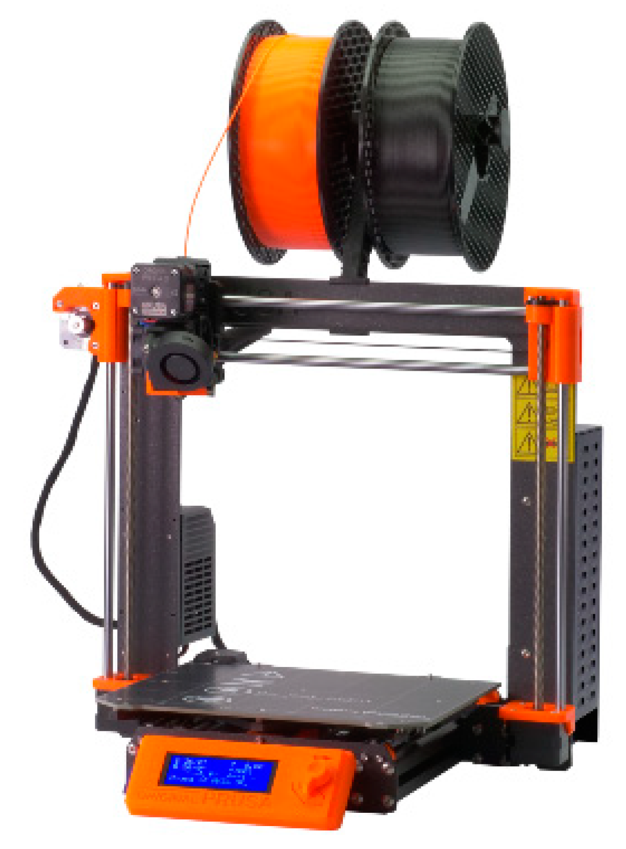
To this end, a 3D model of the mold was designed using appropriate software. Subsequently, this 3D model was transformed into a suitable environment for 3D printing. An Original Prusa i3 MK3S 3D printer was used for production of the mold (see
Figure 2). This printer offers a printable space of 25 × 21 × 20 cm and a total printed volume of 10,500 cm
3. The original E3D V6 jet for 1.75 mm string enables faster printing at a print layer height of 0.05 mm. White polyactide fiber (PLA) was chosen for the production of the mold. The material used is universal for 3D printing and has relatively high strength. This material also withstands temperatures up to 60 °C and resists deformation during the cooling process [
31].
Initially a mold consisting of two parts (base and matrix) was modeled and produced. The base had dimensions of 140 × 70 mm with stops in the corners to fix the position of the matrix. The matrix with dimensions of 130 × 60 mm allowed for the production of three carriers with dimensions of 30 × 7 × 2 mm. The matrix incorporated a channel for locating the microwire in the middle of the carrier body (see
Figure 3).
Several carriers made of various materials based, for example, on epoxy, acrylate, polyurethane, or silicone, were made using this mold. However, when using some of these materials, the carriers adhered to the bottom of the mold and the material fused into the protrusions and grooves of the base. For this reason, a different three-part mold with more forms for carriers was developed. The new, middle part of the mold was designed to be smooth and removable. This form proved successful and was used to prepare potential carriers for microwires (see
Figure 4).
3. Results
As mentioned above, the task of finding suitable carriers was part of theoretical and experimental research focusing on non-contact detection of strains in built structures using amorphous glass-coated microwires. The microwires used in these experiments were prepared using the Taylor–Ulitovsky method [
32] from a metallic ingot with a nominal composition of Fe
76Si
9B
10P
5 and high magnetostriction of approx. 30 × 10
−06. The diameter of the amorphous metallic core was approx. 28 μm, and the total diameter with the glass coating was approx. 48 μm (see
Figure 5).
In our case, microwire carriers were placed on the surfaces of structural members using a suitable adhesive. During the loading of these members and the measurement of their relative deformations (strains), the following interactions were primarily monitored:
When designing the most suitable carrier for the microwires, it was necessary to experimentally specify:
The geometry of the carrier (length, width, and thickness); and
The material of the carrier and type of adhesive used.
For testing steel and wood-based members, carriers with a width of 7 mm and a thickness of 2 mm were used. Steel is a homogeneous material, so carriers with a length of 30 mm were used to measure the strains of steel members. Wood-based materials are anisotropic with fibers connected to each other with relatively weak bonds, so carriers of greater length (100 mm) were used in testing such members. Subsequently, depending on the size of the carrier, a suitable pre-produced matrix was used. The configuration of the carriers is schematically illustrated in
Figure 6.
When choosing a suitable carrier material for microwires, the chosen material should meet the following requirements:
It must adhere well to the microwire, so as to act as one unit;
It must be sufficiently flexible, so as not to limit the tensioning or compressing of the microwire during the loading process of the structural member; and
It must have permanent structure (constant material properties).
In order to meet the above requirements, various materials with a wide range of chemical compositions were gradually tested for the production of carriers. Transparent and non-transparent materials based on epoxy, acrylate, polyurethane, and silicone were tested.
Epoxy-based material (SUPER EPOXI UNIVERSAL) is transparent, waterproof, and has high abrasion resistance. The disadvantage was the high adhesion and hardness after drying. The material did not meet the condition of elasticity, so it was excluded from the selection.
Acrylate-based material (Acrylic caulk) is non-transparent, water-resistant, relatively elastic after drying, and suitable for use in a wide range of building materials. Carriers made of this material had a rough surface. Due to the lack of transparency, it was not possible to check the position of the microwire in the carrier or the quality of adhesion of the microwire with the carrier. This material was also excluded from the selection.
Polyurethane-based material (Bond Flex CRYSTAL polyurethane) is transparent, durable, and elastic. The problem with this material was that it was very sticky and after drying it was difficult to remove from the mold without damaging the carrier.
Silicone-based material (Neutral silicone OXIM) is transparent caulk, water-resistant, permanently elastic, and suitable for use in various building materials. During application, the material adhered well to the microwire and the carriers could be easily removed from the mold, so this material was judged potentially suitable for the production of carriers.
After the experiments with different kinds of material, transparent silicone caulk was selected and proved to be a suitable material for the production of microwire carriers. The application and implementation of silicone carriers with microwires during experimental tests of non-contact detection of strains by means of microwires are illustrated in the following
Figure 7 and
Figure 8.
For verifying the behavior of the designed carrier with microwire, several experimental tests were carried out. Besides the microwire, strain gauge was also used for further analysis and for comparing the obtained results. The average response values of the microwire and the strain gauge during the loading and unloading process of the tested plywood cantilever are illustrated in
Figure 9.
4. Discussion and Conclusions
So far, several pilot tests have been performed for the non-contact detection of strains in structural members using microwires. The loading and subsequent unloading processes were repeated during the tests. For simpler analysis of the microwire feedback, the structural members were tested in the elastic stage of stress in order to exclude the effects of their elastic–plastic behavior.
Over time, silicone-based carriers retained their elasticity and texture. The interactions between the carrier and the adhesive, as well as the binding of the carrier to the microwire, were monitored during the tests. In addition to the recordings from the measuring apparatus, the contact surfaces were analyzed and monitored under a microscope. In order to discover the interaction between the adhesive and the surface of the investigated member, tests were also carried out in such a way that the microwires were glued directly to the surface of the structural members. It can be stated, however, that the individual contacts and the monitored contact areas were maintained intact during all tests.
Although the same type of elastic adhesive was used, differences in the results were found between the tests with direct gluing of the microwire, compared to the tests using the carriers. These results are currently being analyzed. It is provisionally assumed that the adhesive (in the case of direct gluing of the microwire to the structural member) could partially limit the elongation or shortening of the microwire, whereas the carrier provided the microwire with a sufficiently flexible environment. Currently, the results of tests carried out on members made of other materials, such as reinforced concrete and asphalt, are also in the process of analysis.
Existing research projects and serious studies by various authors focusing on this topic have shown that the method of non-contact detection of strains using amorphous glass-coated microwires is innovative and has good prospects for wider use in various areas of research and practice.
The research and preliminary results presented in this paper demonstrate the topicality of this issue, the need for follow-up studies, and the continuation of experimental and theoretical investigation.

 ,
, 
