1. Introduction
The objective of cushioning of a linear hydraulic cylinder is the gradual reduction of the velocity at the end of the stroke, in order to preserve the structural integrity and to avoid undesirable motion of the displaced load. Ideally, a constant reduction of the velocity is desired. The cushioning design used should accomplish this objective with effectiveness in all of the operating ranges of the cylinder at the minimum pressure. Besides, it should be adaptable to the application’s needs, with a restrained cost.
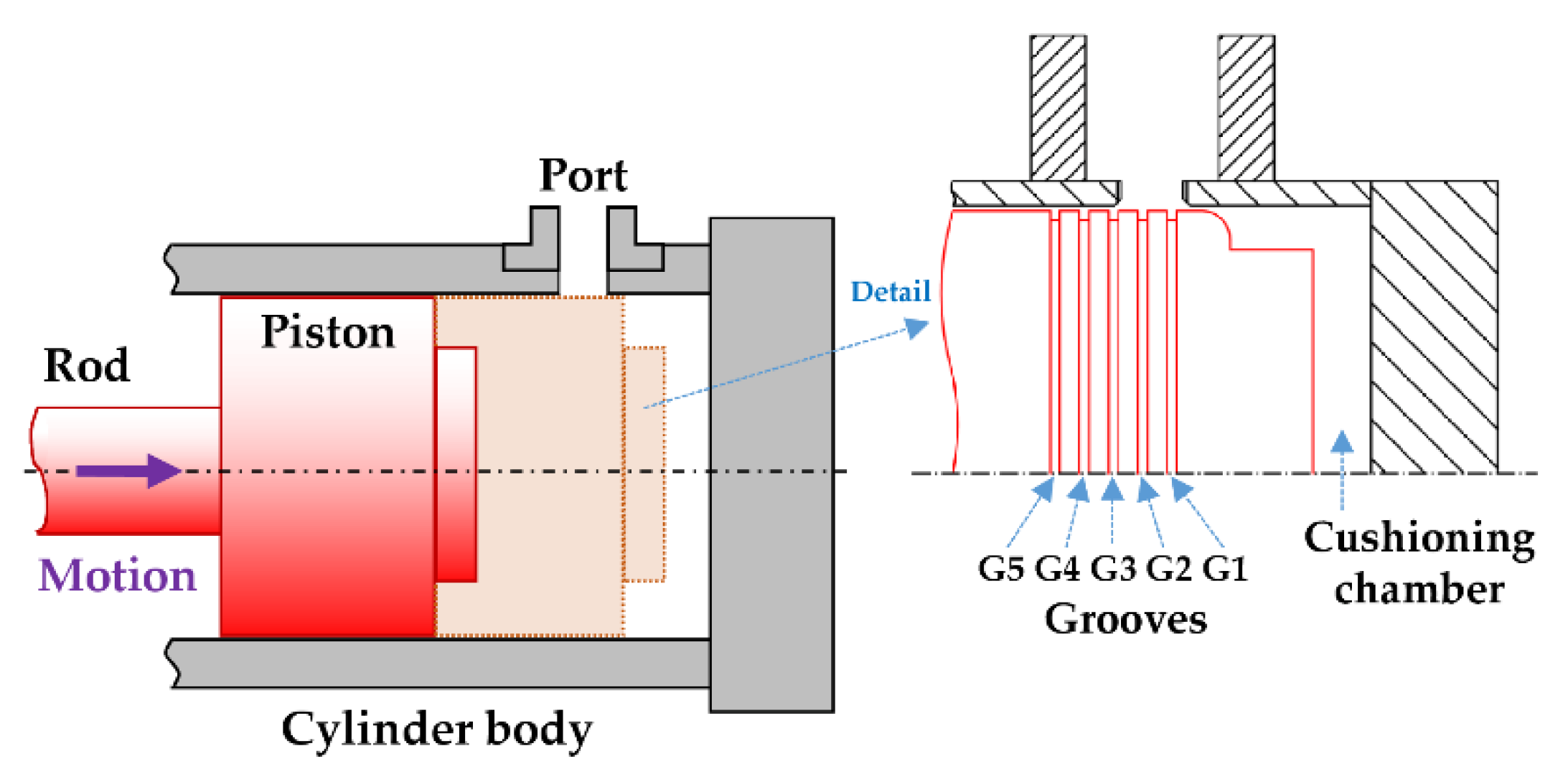
The objective of our study is the design of an end-of-stroke cushioning system, as presented in
Figure 1. Its operation principle is the modulation of geometry of the discharge orifice (ports of the cylinder) using the piston body. Thus, once the piston reaches the ports, the outlet section is restricted, providing high impedance to flow around the interspace between the piston and the internal cylinder wall. Consequently, an increase of the pressure and a deceleration force are generated.
By using the elements of the hydraulic cylinder itself, the proposed design is an easily manufactured and low-cost cushioning system, intended to be especially suitable for off-road application, such as mobile construction machinery.
Several designs have been proposed in order to modulate the cushioning and starting performance. One is the use of peripheral mobile rings, which actuate like a check valve during the cushion and starting phases [
1,
2,
3]; the other is the use of peripheral grooves, whose number and design modulate the outlet section. Until now, this last design had garnered low levels of interest by academic studies, and it is therefore the object of our research; certain key operating factors, like the radial displacement of the piston, have already been experimentally identified in our previous work [
4].
Optimal damping performance is based on a proper balance between kinetic energy dissipation of inertial masses and pressure gradient generation. Due to the complex geometries of a throttled outlet orifice along the cushioning stroke, where the flow regimen changes with the operating conditions, area evolution, and flow rates, a single analytical model is considered a significant simplification of the real performance [
5,
6,
7,
8,
9,
10].
On the other hand, computational fluid dynamic simulations (CFD) are a suitable tool for the identification of local phenomena like flow, internal pressure, or stress distributions in cushioning devices [
9,
11]. However, the large time demand of these simulations makes them impractical for dynamical systems modeling.
Conversely, the bond graph technique has demonstrated suitable performance in simulating complex dynamical mechanical and hydraulic systems. The bond graph methodology models the energy exchange between subsystems or components that interact with each other. The basis of this methodology is to create a map of power fluxes throughout the system under study. Since it is based on the first law of thermodynamics, the energy flux map of the system is applicable in the transfer of power between the limits of the different disciplines of engineering. Bond graphs thus reflect the real, physical structure of the system and the links between its different components.
The following presented papers study the applicability in hydraulic systems and the easy modulation of the complexity of the bond graph model according to the nature of the required objective [
12,
13,
14].
Bond graph modeling also shows a powerful applicability in analyzing the control strategies of dynamical mechanical and hydraulic systems [
15,
16,
17]. Besides, it has also been successfully employed in detailed analyses of small-scale mechanical and hydraulic systems, such as pressure regulation valves [
18,
19].
In consequence, the bond graph technic has been revealed to be a very useful technic for modeling dynamic hydraulic and mechanical systems. Used for numerous hydraulic systems analyses, works considering the cushioning of hydraulic cylinders are not reported.
In this context, this paper presents a bond graph model of a linear hydraulic actuator and a constant flow power circuit including a novel model of the cushioning by peripheral piston grooves. The model highlights the dynamic effects induced by the radial displacement of the piston over the flow regimen. Hence, flow regimes observed in previous experimental experiences and analyzed by CFD discharge coefficients are included in the model. In the last instance, the performance of the cushioning system is assessed during a real application of the cushioning during the movement of the arm of an excavator.
This paper is organized as follows.
Section 1 presents the state of the art and the introduction of the work exposed in this paper.
Section 2 details the bond graph model and system equations.
Section 3 details the novel developed cushion model.
Section 4 presents the CFD analysis and the main numerical results.
Section 5 details the experimental work by operating a hydraulic cylinder installed in an excavator arm.
Section 6 describes the main results of the investigation. Finally, in
Section 7, conclusions about the cushioning performance are discussed.
2. Bond Graph Model
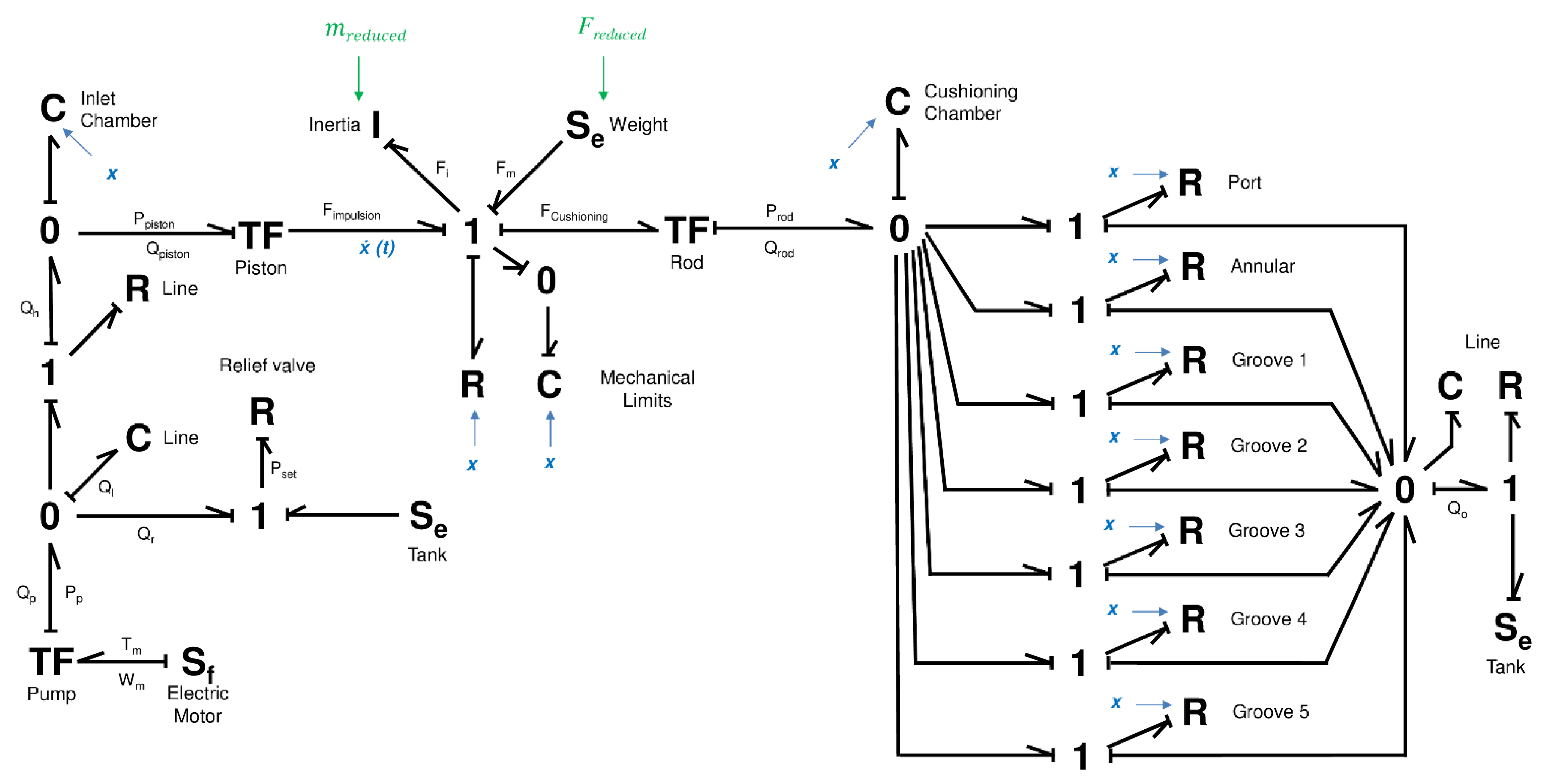
The developed bond graph model is shown in
Figure 2. Following the usual bond graph nomenclature, the model includes elements as flow sources S
f, effort sources S
e, transformers between physics domains TF, capacitances C, resistances R, and inertia I. Finally, in the 0-junctions, all effort values are equal across the bonds and in the 1-junctions, all flow values are equal across the bonds.
The model is divided in two differentiated parts; left hand is a state-of-art hydraulic cylinder and constant flow supply circuit model; right hand describes a novel end-of-stroke cushioning device model.
The model is constructed according to the following assumptions:
Resistive and capacitive effects are lumped wherever appropriate.
There is no leakage between the piston chambers
Internal Friction of the cylinder is not considered
Fluid inertia is not considered.
The tank pressure is assumed to be equal with the atmospheric pressure.
Newtonian fluid is considered for the analysis.
The oil temperature and hydraulic fluid viscosity are constant.
In this particular case, the cylinder extension is represented, being the inlet performed in the piston chamber and cushioning produced in the rod chamber. Instead, the model can also be used to represent retraction of the cylinder, exchanging the role of each chamber. Respecting integral causality, causality is established using the sequential assignment procedure.
The key and novel elements of the bond graph model are described in the following sections. The well-known description of the remaining state-of-art elements, such as pump, pipes, cylinder chambers, or relief valve, is omitted, previously explained in several studies [
13,
16,
20].
2.1. Cylinder Rod
The one junction represents, in the mechanical translation domain, the force balance experimented by the cylinder rod. The inertia modeling allows calculating the obtained operational velocity.
where
Fi is the inertial force and
Fm is the weight of the displaced reduced mass to the cylinder rod, considered constant.
For the calculus of the inertial force, the general relationship between force and a reduced mass
mreduced, for single degree of freedom systems, such as the studied one, is established according to the well-known Eksergian equation [
21,
22]:
In the described context, it should be noted that Equation (2) is simplified in Equation (3). The adopted simplification, as described in the bibliography [
23], was estimated to be suitable due to the low velocity existing during the cushioning, and also due to the constant reduced mass at the retraction cushioning. The results from this consideration are evaluated in the section of simulation analysis.
Following this, a Rlimit element is included representing the mechanical limits of the piston, where an “infinite” resistance is generated when the cylinder reaches its end of stroke. In order to avoid an unrealistic stiff response, the mechanical elasticity of the cylinder body, once reaching the end of the stroke, is represented by a Climit element.
2.2. Excavator Arm Model
In this moment, a model of the force and mass transference from the structure to the cylinder rod is introduced. In this case, the inertial force and the mass are highly influenced by the mechanical design of the excavator arm under study. It should be noted that this work is a practical and simplified approach to the complex kinematics of an excavator arm, which has been the subject of research in different sources [
20,
24,
25].
For this reason, a series of simplifications are established in the planar dynamic model as detailed below and corresponds to the conceptual scheme of the excavator shown in
Figure 3.
The inertial effects of the hydraulic cylinder mass are considered negligible.
The hydraulic cylinder is only subjected to forces in the same direction as its axial axis.
The frictional forces on the seals and links are negligible.
Links and mechanical fixing points are perfectly rigid.
The fixing points with the cylinder, the center of rotation, and the supported masses are aligned on the same axis.
Only the action of the cylinder on the shown arm is considered.
The mass of the arm and the other existing moving masses (load) are in the earth’s gravitational field moving with a variable acceleration. This generates a force acting on the cylinder displacing them, called reduced force (Freduced), resulting from the effect of the mass forces and the geometry of the mechanism.
Then, the calculation of the reduced force is given by the following expression:
where
Fi is the different forces present in the system and
L is the distance traveled.
For our particular system, deriving the previous expression we obtain:
where
vcylinder is the velocity of the cylinder rod relative to cylinder body,
vown is the velocity of the excavator arm referred to its center of mass,
vload is the velocity of the displaced load and
g is the gravity acceleration. In
Figure 3, the
mown,
mload, and angles
τ and
δ are graphically described. It should be noted that the angles
τ and
δ are determined essentially identical by geometry.
During the retraction movement of the cylinder, represented in
Figure 3a, the reduced force has a negative sign due to it is in opposition the direction of movement (resistive load). On the other hand, for the cylinder’s extension in
Figure 3b, the reduced force has a positive sign, in the same direction of the movement (overrunning load).
With an angular velocity
ω, it is verified for the studied system that:
where
rreduced,
rown,
rload,
vreduced, and
θ angle are graphically described in
Figure 3. Finally, Equation (7) reduces to:
In consequence, the reduced force depends on the existing masses, the rotation radius, and the geometrical angles of the system. These angles
θ and
δ evolve in relation to the extension of the cylinder
x, as shown in
Figure 4.
On the other hand, we define the reduced mass as that equivalent point mass that, located at the end of the rod, has the same kinetic energy as the arm and the other mobile masses. In the evaluated system, the angular velocity of the hydraulic cylinder is very small, so only the relative velocity of the rod inside the cylinder body will be considered.
The calculation of the reduced inertial mass is carried out from the following expression:
where
Ec reduced is the kinetic energy of the reduced mass and
is the kinetic energy of the remaining masses of the system.
For the system under study, the previous expression is established as:
which leads to the final expression for the reduced mass:
where the moment of inertia of the load is:
where
rdisk is the radius of the disk acting as a load on the experimental device.
On the other hand, the calculation of the momentum of inertia of the arm of the excavator, called
Iown, as well as the determination of its center of mass, is carried out from a 3D model in a CAD tool (free software FreeCAD
® V0.13) [
26,
27], obtaining the following value:
Equation (11) calculates reduced mass values as detailed in the following
Figure 5. Here, the resulting reduced mass acquires a very high value, which grows quasi-exponentially approaching the extension end-of-stroke, mainly due to the evolution of the angle
θ.
3. Cushioning Model
3.1. Design Parameters
The cushioning performance is intended be controlled by the presence of perimeter grooves in the piston surface. Considering
X0 as the position where the piston entirely closes the outlet port of the cushioning chamber, the characteristic parameters of the studied cushioning design are detailed in
Figure 6 for 5 perimeter grooves (
G1 to
G5). The grooves have a rectangular section of width
bi and depth
hi, separated from
X0 a distance
Li, for
i = 1 to 5.
D is the diameter of the outlet port. The radial assembly clearance between piston and cylinder body inner wall is defined as
e.
It should be noted that the order of the grooves follows the motion of the actuator, with G1 being the first and G5 being the last to be in front of the outlet port.
Figure 6 shows this distribution in the extension movement and previous
Figure 1 shows it for the retraction movement.
3.2. Cushioning Phases
As the cylinder approaches to its end of stroke, the piston closes the fluid outlet port, starting to narrow the flow section and producing a resulting cushioning pressure. The performance of this type of cushioning devices has been experimentally assessed in detail in our previous work [
4].
As graphically detailed in
Figure 7, we observed that the perimeter piston grooves modulate the output flow during the last phases of the cushioning thanks to their section distribution and the evolving radial gap.
Thus, the studied design produces cushioning in three phases named as Port flow, Annular flow, and Groove flow, as depicted in
Figure 8. Each phase is characterized by a different flow section due to the particular position of the piston in relation with the outlet port. Despite that different flow paths are deployed in parallel in the bond graph model, they are programed in function of
x position in order to appear in coherence with the geometry of the actuator and the documented behavior.
It should be noted that these described cushioning phases are based in the evidences registered by the CFD investigations, first detected in our previous work [
28]. All the observed flow facts are represented in the dynamic simulation model developed.
The port flow,
Qport, works from the coincidence of the piston with the outlet section of the port until its total occlusion. It is modeled from the classical sharp-edged orifice turbulent flow equation, where the flow is proportional to the square root of the pressure drop in the orifice Δ
p [
29]:
where
Cd is the port discharge coefficient and
ρ the density of the fluid. The pressure drop is considered equal to cushioning chamber pressure due to outlet port is discharging to tank at atmospheric pressure, i.e., Δ
p ≈
Pcushioning. The effective flow section S
port changes as a circular segment.
Once the advance of the piston covers all the section of the outlet port, the outlet section is produced through the annular section existing in the small gap between the piston and the cylinder body. The annular flow,
Qannular, is modeled as,
where
d is the diameter of the inner wall of the cylinder,
e is the annular gap between the piston and the inner wall of the cylinder,
μ is the dynamic viscosity,
l is the length of the flow channel, and α is the angle limiting the width of the annular flow channel, starting from the vertical. This equation is the well-known Poiseuille equation for stationary laminar flow between two planes, calculated for annular section geometry. The annular space is revealed as a key factor in the annular flow, where the flow is affected by the cubic value of the gap.
It should be noted that Couette flow influence has been neglected in this numerical model. As determined, this simplification has a minor influence in the results, below the 2%, in the usual operating conditions.
Once the first groove reaches the outlet port the groove flow,
Qgroove, appears. This flow is also modelled with the sharp-edged orifice flow equation where
The equation considers that the section of the section of the groove, Sgroove, exists in both sides of the piston in front of the cylinder port. As detailed in next section, the grooves discharge coefficient Cd are determined from the numerical results of CFD simulation.
4. Computational Fluids Dynamics
The presented dynamic bond graph model needs to have an adequate relationship with the real application. For this reason, the computational fluid dynamics (CFD) simulation has been validated and refined according to experimental records. The final goal is to obtain an affordable methodology for quantitatively complete the dynamic model and for the identification and characterization of the existing internal flow phenomena.
For this reason, shown in
Figure 9, a 3D model of the end-of-stroke hydraulic cylinder was created, including the cushioning chamber, cylinder body with the outlet port, and the piston with five perimeter grooves. Thus, these elements form the limits of the volume where the cushioning occurs. That is, where the hydraulic oil flow around the defined geometry, leaving the cushioning chamber, and generating the pressure drop.
By a simple manipulation, the 3D representation allows changing the relative position of the piston according to the outlet port, gradually approaching its end-of-stroke.
In addition, it is possible to evaluate the distance between the cylinder body and the piston, being the radial gap
e between them. Thus, three possible positions, Centered, Intermediate, and Attached, are established, in relation to the position in the
z-axis. It is schematically described in
Figure 10. It should be noted that a centered position of the piston in the horizontal
y-axis has been always considered.
The development of computational fluid-dynamics model used in this paper is described in detail in our previous work [
28]. In this case, for a suitable fitting with the experimental records, we include some improvements in the geometry refinement and, more significantly, a denser mesh up to 3.1 M elements, most of them being of hexahedral type.
The simulations have been performed with the open-source OpenFOAM
® version 6 [
30,
31] software (managed by OpenCFD Ltd., Reading, UK), using the Semi-Implicit Method for Pressure-Linked Equations (SIMPLE) resolution algorithm [
32] implemented in simpleFOAM solver. The SIMPLE solver solves the standard Navier-Stokes equations in steady state, neglecting the effect of gravity, for incompressible and Newtonian fluids. Laminar flow is imposed in all the experiments.
The developed CFD simulation model is suitable for the analysis of the dynamic flow phenomena during the cushioning, depending on the radial position. For the centered position, the flow is produced mainly throw the annular space between the piston and the cylinder body; only a part is done through the grooves. Besides, due to the pressure distribution in the cushioning chamber, the flow is only produced in a small portion of the perimeter, mainly near the port. On the other hand, flow is produced only through the grooves for attached positions of the piston; here, the grooves receive the hydraulic flow from the interspace between the piston and the cylinder body by a pronounced pressure gradient directed to the output port. The described flow patterns are shown in
Figure 11.
In consequence, depending on the number of the piston grooves, the observed outlet flow generates a significant transversal force as shown in
Figure 12. The generated force would be the cause of the transversal movement of the piston inside the cylinder body during the cushioning, experimentally observed [
4].
Following, the discharge coefficients
Cd are calculated using Equation (16) below, obtained solving the Equation (15). This considers the groove section,
Sgroove, existing on both sides of the piston in front of the cylinder port.
From the numerical results of the CFD simulations, a specific methodology is established to determine the average flow velocity through the section of each groove, immediately before discharge at the outlet port. As shown in
Figure 13, a section cut of the velocity field is made on each side immediately before the port. The cutting area is detailed in the dotted area. In the shown example, the flow occurs only in the two interposed grooves 2 and 3 in front of the port.
Finally,
Figure 14 shows the distribution of discharge coefficients obtained for the piston’s design Version 1 in grooves 2 and 5 along their stroke, supply flows, and radial position. These results are exclusively related with Version 1 design and they should be evaluated for each change in grooves design.
The equation of the plane that this data forms is calculated as a mathematical representation of the results. These have the general form of the following equation:
where
Lp is the piston stroke (in centimeters) and
Qgroove is the flow rate through the groove in (in L/min). The coefficients
a,
b, and
c, detailed in
Table 1, are determined by least-squared best-fit for the different established experiments.
The already explained confidence of the pressure value obtained by simulation causes a maximum uncertainty of the obtained Cd value of ±0.07. On the other hand, the mathematical extrapolation of the plane equation of the discharge coefficients, due to the implied simplification, turn in a maximum RMSE error of ±0.04.
5. Experimental Method
The experimental setup is composed by a hydraulic circuit and monitoring sensors as are shown in
Figure 15. This is based on a double-acting hydraulic cylinder [55 × 35 × 365] (A1) assembled in the arm of an excavator.
The actuator is powered by a constant flow pump (P1) driven by a motor (M1). The maximum pressure supply is adjusted by a pressure relief valve (V1). The direction of movement of the hydraulic cylinder is controlled by a directional valve (V2). The monitoring of the displacement of the piston and pressures of the hydraulic circuit is done by the listed sensors (S1 to S6) and recorded by National Instruments data acquisition system USB-6343 NI- and 2010 Labview software.
The experimental work is performed for two versions of the piston with five perimeter grooves, as detailed in the
Table 2. Both designs have the same radial gap, but version 3 has a higher groove transversal section (deeper) than version 1.
The experimental set-up used in the excavator arm, including the main dimensional parameters, is presented in
Figure 16.
The excavator arm has been modified substituting the bucket by removable disks acting as loads. The retraction movement of the actuator is related to the lifting of the arm and the extension movement with the fall of the arm.
6. Results
As evaluated in the previous section, the complex dynamics of the arm of the excavator presents important differences between the retraction stroke and the extension stroke of the hydraulic actuator. In this context, the cushioning behavior is experimentally evaluated.
6.1. Cylinder Retraction
For cylinder retraction the inlet chamber is the rod chamber, and the cushioning chamber is the piston chamber. The retraction movement of the actuator is related with the lifting of the arm of the excavator and the load located at its end.
The general behavior observed in
Figure 17 is perfectly related to the evolving flow section according to the presence of one or two grooves in front of the outlet port.
First, the actuator approaches the end of stroke at a steady velocity, increasing with supply pressure and decreasing with load, which would be consistent with a high resistive load situation. In other words, the stress associated with the existing reduced force would condition the maximum reached velocity. It should be remembered that the hydraulic circuit has a constant flow pump and a pressure-limiting valve to regulate the pressure, as described in
Figure 15.
Following this, the piston’s velocity undergoes a sudden reduction (cushioning) in coincidence with the obstruction of the port and the presence of the first two piston grooves. This leads to a moderate pressure peak in the cushioning chamber, around 1.5 times the supply pressure. In this phase, the inlet pressure reaches its maximum value preset by the pressure relief valve.
During the last 18 mm of stroke, there is a slow approach to the end of the stroke, at a velocity of less than 100 mm/s to imperceptible values. This evolution is similar regardless of the operating conditions.
Finally, for higher supply pressures and loads, less smooth “stop and start” movements are observed along the last millimeters of stroke. This is manifested by the existence of a sporadic zero speed and a sudden drop and rise in the cushioning pressure. This behavior could be explained as a hydrodynamics effect lose. At very low piston velocity, the balance effect of the grooves centering the piston [
33] and, also the drag force of the outlet flow to attached position, disappear. In consequence, the free piston’s position is potentially affected by other mechanical phenomena like structural vibrations.
On the other hand, the higher section of the first three grooves in the version 3 piston leads to a more gradual velocity profile obtained during the retraction cushioning. Besides, a lower pressure is obtained in the cushioning chamber. This behavior is detailed in the comparison shown in the
Figure 18.
This comparison shows how the difficult transition between the port obturation and the start of the groove flow phase can be modulated with a higher section in first grooves, obtaining a more favorable pressure and velocity response.
6.2. Cylinder Extension
The general behavior of extension cushioning is very different in comparison with retraction cushioning. In this case, the dynamics of the excavator’s arm imposes a reduced force and, especially, a reduced mass evolving along the cylinder stroke, reaching its maximum value at the end of the extension movement.
In the direction of extension, the piston chamber is the inlet chamber, and the rod chamber is the cushioning chamber. The actuator extension moves the excavator arm in a falling motion. As described below, on the downward movement of the arm it faces a significant runaway load, resulting in a free fall and an inlet chamber depression.
The behavior, as shown in
Figure 19 and
Figure 20, follows the following general aspects described.
First, there is a moderate local loss of velocity, before the start of cushioning. This happens without an apparent effect on the pressure in the cylinder chambers. The reduction in velocity by the cushioning occurs abruptly up to 10 mm before the end of the stroke, observing a total or almost total reduction in velocity. This also shows a pressure peak in the cushioning chamber, which is not affected by operating conditions.
During this runaway condition, the impulse pressure remains zero. Due to the dimensioning of the used hydraulic pump, the impulse flow is not enough to fill the piston chamber. In this free-fall situation, the cushioning system only has to absorb the variation in kinetic energy (reduced mass) and the work generated by the reduced force.
Following this, during the last 10 mm of the stroke, a slight increase in velocity is observed until reaching the end of the stroke. This happens with a second pressure peak in the cushioning chamber and the appearance of the nominal inlet pressure. Therefore, this secondary pressure peak increases with increasing supply pressure.
For increasing supply pressure and loads, a marked rebound effect is observed, visible in the velocity and pressure curves, in the last millimeters of stroke.
Besides, the version 3 design shows a more pronounced general behavior, with a greater presence of rebounds and a higher cushioning pressure than the version 1 design.
6.3. Simulation Analysis
The bond graph simulation is performed with the simulation software 20-sim © version 4.2.7 developed by the company Controllab Products B.V. (Enschede, The Netherlands). The implemented model uses the backward differentiation formula (BDF) calculation method with a step size of 10−6 and an absolute and relative integration error of 10−6.
Thanks to the developed dynamic bond graph model, the obtained experimental results can be compared with the numerical simulation results. For this reason, the different operational parameters, dimensions of the piston, as well as the evolution of the reduced mass and the reduced force along the actuator stroke are imposed. Besides, an α = 22.5°, for Equation (14), is estimated from CFD numerical results [
28]. In this way, only the evolution of the radial gap along the cushioning needs to be defined. It should be noted that the radial movement needs to be adjusted for each particular experience.
Due to technical limitations the radial displacement has not been measured experimentally. So, the evolution of the radial gap has been estimated based on the acquired knowhow during the research work. The results of the used radial gap profile are shown in the following
Figure 21.
Regarding retraction cushioning, shown in the
Figure 21, a good fitting is obtained between the results, with an average divergence in velocity of 6.5%, detecting a maximum difference of 55 mm/s at 20 mm of stroke.
In general terms, we can sustain that the behavior of the retraction cushioning is largely governed by the evolution of the radial distance, where the overpressure in the cushioning chamber is affected by the imposed law of the radial flow and the radial gap profile. Tests have shown that the cushioning chamber pressure behavior is very sensitive to radial position.
We see that piston move towards an attached position from the appearance of the grooves at the end of the port closure. As a result, a velocity inflection is observed at about 17 mm from the end of the stroke, also especially observable on the cushioning pressure.
It must be said that the numerical model does not predict the observed “stop and start” effect of the piston velocity near the end of the stroke. This fact would reinforce the theory that this phenomenon would be caused by the loss of the hydrodynamics of the piston and external influences, circumstances not considered in the described model.
On the other hand, the extension cushioning is clearly governed by the evolution of the reduced mass and force, which have, as already stated, a marked evolution during the extension end-of-stroke. This could be, among others, the cause of the local loss of velocity observed before the cushioning.
Although a possible radial distance profile has been determined, it has a relatively low effect on dynamic behavior, but with an appreciable effect on pressure response.
In this case, the model results in extension shows a worst fitting in comparison with to the retraction results, with an average difference in velocity of 34% with a maximum difference of 114 mm/s at the start of the cushioning; in general, the velocity is underestimated simulating extension cushioning. These divergences could be caused by the simplifications made in the numerical model representing the evolution of the reduced mass and force. The results are depicted in
Figure 22.
In any case, despite the simplicity of the model, it allows to evaluate the main causes of the observed behavior and the main influence parameters. So, the first pressure peak is governed by the mechanical stress conditions imposed by the reduced mass and force model and, in consequence, we can hardly infer through the design of the cushioning device or the operating conditions.
On the other hand, the second pressure peak, which is originated from the rebounds at the end of stroke is influenced by the supply pressure and, in a minor degree, by the existing radial distance.
7. Conclusions
The obtained results show, in general, an effective velocity reduction obtained for all the studied cushioning designs, regardless of the operating conditions.
In any case, considering that the used hydraulic cylinder was not specifically designed for this specific application, there is no homogeneous efficiency for a cushioning design, being in some cases insufficient. Even for very small end-of-stroke velocity, there would be a high kinetic energy gradient that the cushioning system is not able to fully contain, revealed as rebounds.
Apparently, the retraction cushioning is governed by the radial distance and, especially, by the reduced passage section of the last perimeter grooves, allowing the design of the cushioning system modulate the behavior of the system. The obtained velocity would be, in general, consistent with the geometry of the cushioning system and influenced by the architecture of the hydraulic supply circuit, especially by the dynamics of the pressure limiting valve.
The obtained results by dynamic simulation show an adequate concordance with the experimental records. In any case, the extension cushioning, governed by the mechanical dynamics of the system, is significantly affected by the simplifications of the presented model. In the described situation, the design of the cushioning device cannot sufficiently control the extension behavior of the case under study.
Although it is out of the scope of this study, it would be of future interest to evaluate the influence of operative and constructive factors of the mechanical system over the cushioning. For instance, co-simulation is an excellent option for the optimization of mechanisms powered by hydraulic systems.


