Article

Geomechanical Characterization of a Rock Cliff Hosting a Cultural Heritage through Ground and UAV Rock Mass Surveys for Its Sustainable Fruition

by
Simone Mineo
1,
Giovanna Pappalardo
1,* and
Salvatore Onorato
2
1
Department of Biological, Geological and Environmental Sciences, University of Catania, Corso Italia 57, 95129 Catania, Italy
2
SOAGEO S.r.l. Via Feudo Stella, 18 Paternò, 95047 Catania, Italy
*
Author to whom correspondence should be addressed.
Sustainability 2021, 13(2), 924; https://doi.org/10.3390/su13020924
Submission received: 3 November 2020 / Revised: 13 January 2021 / Accepted: 14 January 2021 / Published: 18 January 2021

Abstract

:
In mountainous areas around the world, dealing with rockfalls means facing some technical survey difficulties due to the low accessibility of areas and the height of slopes. If a cultural heritage is also threatened by such mass movement, the need of specific survey solutions, even in a combined asset, is required. This paper deals with the integration of ground and UAV rock mass surveys aimed at defining the rockfall attitude of an unstable rock cliff sector hosting an example of cultural heritage in tourist area of southern Italy, whose fruition has already been threatened by the occurrence of rockfalls. As an example of the defensive architecture of XII and XIII centuries, the Saracen Castle in Taormina is reached by hundreds of visitors each year, but its access path and the surrounding area are threatened by the unstable condition of the cliff, hosting unstable rock volumes on kinematically critical planes. In order to achieve a reliable geostructural setting of the cliff, aiming at its possible securing through proper mitigation works, ground rock mass surveys could not provide enough information due to the bad accessibility of the rock faces. Therefore, a survey by an Unmanned Aerial Vehicle, with a reliable verified accuracy, was carried out to map the discontinuity planes especially occurring at the highest portions of the cliff, achieving geostructural data of different fronts of the cliff. Ground and aerial data were combined and statistically analyzed to define the main kinematic failure patterns. In this perspective, a critical comparison between the two employed surveying methodologies is proposed herein, highlighting that both approaches are affected by potential and limitations and that the integration of the mutual dataset represents a suitable solution for a complete rock mass characterization in this type of areas. Furthermore, rockfall simulations allowed ascertaining that potential falling blocks would cross the access path to the castle, thus representing a natural threat to the fruition of cultural heritage, thus proving the need of mitigation measures to ensure the safe fruition of the cultural heritage.

1. Introduction

As a part of human history, cultural heritage represents a treasure deserving protection and careful management to ensure its transfer to future generations. Historical sites are often cultural tourism destinations, and their safe fruition is a priority for local administrators. In mountainous settings, where often historical buildings have been erected for strategic purposes, one of the most recurring threat is represented by landslides and, more specifically, rockfalls [1,2,3,4,5,6,7,8]. Such mass movements are often the expression of a risk [9,10,11,12,13], which often compromises the fruition of the good, leading to a cultural defeat for our generations. This is the case of the cultural heritage perched on the top of a carbonate cliff facing the Ionian coastline of Sicily (southern Italy), and dominating the town of Taormina. It is the Saracen Castle, an example of the defensive architecture of the XII and XIII centuries, which is part of the monumental park of Taormina. This little town is considered as a natural fortress of great strategic and political importance, and it has been included in the tentative UNESCO world heritage list to be placed under consideration as a possible nominee. This adds relevance to the already worldwide known touristic importance of this place, visited by millions of tourists every year. The rockfall problem has been affecting the castle cliff for decades, with falling blocks, even of considerable volume, reaching the downstream public infrastructures and private structures, and threatening its safe fruition [14,15]. Some rock mass stabilization works were carried out in recent years to stabilize the southern and eastern cliff sectors and to protect some private houses. Nevertheless, the access road path to the castle, along with a panoramic viewpoint and a small rock-hewn church representing tourist destination for their suggestive view and naturalistic impact, are still under the impending unstable rock threat. The main difficulty in the study of such unstable rock cliff is represented by the bad accessibility of the highest rock mass portions, where most of the loose rock blocks stand in unstable condition. In fact, the only survey spots are a few rock outcrops located at the foot of the cliff, which can be surveyed by operators on the ground. In this paper, the geomechanical asset of the cliff bordering the access path to the castle is defined according to the combination of in situ and remote surveys. In the latter case, an Unmanned Aerial Vehicle (UAV) has been employed to reach the highest sector of the cliff and to achieve a close view of the top rock mass conditions. UAV systems were initially employed for military purposes [16] and then, due to their practical utility, were extended to archaeology and cultural heritage mapping, environmental surveys, urban monitoring and tridimensional reconstructions [17,18,19,20,21,22,23,24]. The literature shows that optical imagery and, more generally, remote sensing procedures, have been employed in rockslide surveys [25]. Brückl et al. [26] took advantage of photogrammetry to reconstruct the kinematics of a deep-seated landslide, while Collins and Stock [27] employed terrestrial laser scanning for the hazard assessment along cliffs. Similarly, 3D geometrical data were achieved by some authors [28,29] through automated, or semi-automated, approaches. With specific reference to rock cliffs, Sturzenegger and Stead [30] and Riquelme et al. [31] analyzed rock mass discontinuities through terrestrial photogrammetry coupled with laser scanning and 3-D point clouds, respectively. Mancini et al. [32] investigated the integration between UAV photogrammetry and geomechanical modeling of coastal rock cliffs proving its utility for finite element stability analysis. In the literature, some cases of integration between UAV and ground surveys, with specific references to the successful fracture mapping [33] and rockfall instability study [34,35,36,37], prove the utility of aerial photogrammetric surveys in hardly accessible areas, highlighting also the need for accurate model calibration and validation to achieve reliable results. For example, Salvini et al. [33] proved that UAVs can significantly improve the collection of geometric and structural data when integrated with information from traditional engineering geological surveys, which is one of the main scientific goals of this paper. Robiati et al. [36] provided a back analysis rockfall study through 3D photogrammetric remotely sensed data highlighting the possibility of achieving reliable models after a careful calibration of input parameters. Nevertheless, Rodriguez et al. [37] strengthen the fact that UAV surveys should not replace or undermine the importance of site inspections; rather, it enhances the information to make better decisions. To this end, in this research, from the point cloud achieved by UAV survey, the orientation in the space of the most visible planes has been extracted and compared to those surveyed on ground for a critical evaluation of the scientific and technical utility of potential stand-alone UAV surveys. Based on the achieved geostructural data, the main kinematic unstable patterns were highlighted to find out the entity of the rockfall threat. This activity was sided by rockfall simulations aimed at evaluating the impact of potential rockfalls on the access road path and structures, which led to the suggestion of the most suitable stabilization works for the cliff securing and the sustainable fruition of the cultural heritage.

2. Setting of the Study Area: Cultural Heritage, Geology and Rockfalls

Built by the Arabs on the top of the 400 m-high Monte Tauro cliff (Figure 1a,b), the Saracen Castle allowed a strategic control of both Taormina bay and the valley of the Alcantara river. With its sub-vertical rock scarps and an average steepness of about 40°–45°, this site was probably the location of the antique acropolis of the Greek town Taormina. The Romans, and later the Byzantines, used the same site, which, however, fell to the Muslims in 902 AD after a two-year-long siege. They rebuilt the castle, shaping its current trapezoid plan, which is admirably adapted to the shape of the rock cliff. In 1078, the Norman count Roger I of Sicily, conquered the town of Taormina from the Muslims. In 1134, the castle was used by the San Salvatore la Placa monastery, while in 1240 A.D. it was counted among the belongings of King Frederik II. In 1297, during the Aragon dynasty, this fort was entrusted to the Taormina governor [38]. Nowadays, it is recognized as a cultural heritage site—evidence of the defensive architecture of the XII and XIII centuries located in a unique spot dominating the Ionian coast.
From a geological point of view, the study area lies on the southernmost sector of the Peloritani Mountains, a nappe-pile belt composed of distinct tectonic slices, in turn composed of a metamorphic basement locally covered by sedimentary formations. In particular, the geological unit widely cropping out in the castle area takes its name from the city of Taormina and it is represented by a Variscan epimetamorphic basement, covered by upper Triassic fluvial ‘‘Verrucano-type’’ deposits and lower Liassic greyish-white limestones and dolostones in carbonate platform facies [39] (Figure 1c). This latter lithology represents the frame of the Monte Tauro cliff, where moderate to highly fractured limestones, locally partly dolomitized, crop out. Rock masses are crossed by several discontinuity sets, which are the expression of the heavy tectonic stresses shaping the landscape. In particular, fault segments and thrusts dislocate the geological formations (Figure 1c), and these can be counted among the predisposing factors of landslide movements of the whole area [40,41,42]. Pappalardo et al. [43,44,45] and Pappalardo and Mineo [46] deeply studied the interaction between geology and geomechanical setting of the Taormina area, with focuses on the widespread stability issues representing a tangible risk for the fruition of the district. The most recurring landslide type are rockfalls, often in wedge configurations, affected by relevant volumes (up to 5 m3 for each block). The steepness of the area, along with its high seismicity, enhances the kinetic energy of falling blocks, which are capable of covering relevant distances. With specific reference to the castle cliff, Mineo et al. [14] found out that rockfalls usually originate from the top of the carbonate cliff, where several blocks stand in unstable conditions, and move downstream following the terrain morphology. Among the most recent events, the 2013 and 2015 rockfalls are two of the most hazardous ones. On such occasions, boulders with volumes of about 0.1–0.15 m3 detached from the highest sectors of the rock masses and rebounded along a pedestrian path connecting Taormina center to the Castel viewpoint with a kinetic energy ranging between 50 and 250 kJ [14]. The road, pavement and banister were damaged, but no hurt people were reported. Numerous further events are not documented, due to the lower rock volume involved, but their occurrence is testified by the presence of widespread source areas along the rock face and several low-volume blocks laying at the side of the pedestrian path.
In such a hazardous setting, the tourist path towards the castle entrance represents one of the main elements at risk, and it is recommended caution as no protection measure has ever been settled. Mineo et al. [14] carried out a preliminary hazard assessment along the south and east portions of the cliff, highlighting the poor mechanical features of the rock masses and the high hazard arising from rockfalls. Nevertheless, the access sector was not considered by that study. Mineo and Pappalardo [15] enclosed this spot in a cultural heritage itinerary affected by rockfall risk, highlighting the unexpressed potential of this site due to the rockfall threat. These authors assessed a medium risk affecting even the access road path and the neighboring infrastructures, often crowded tourist destination. Besides the access road path, the main elements at risk are represented by a panoramic viewpoint located right below the unstable cliff, hosting a small rock-hewn church—a place of worship built in approximately 1640 (Figure 1d).

3. Methodological Approach

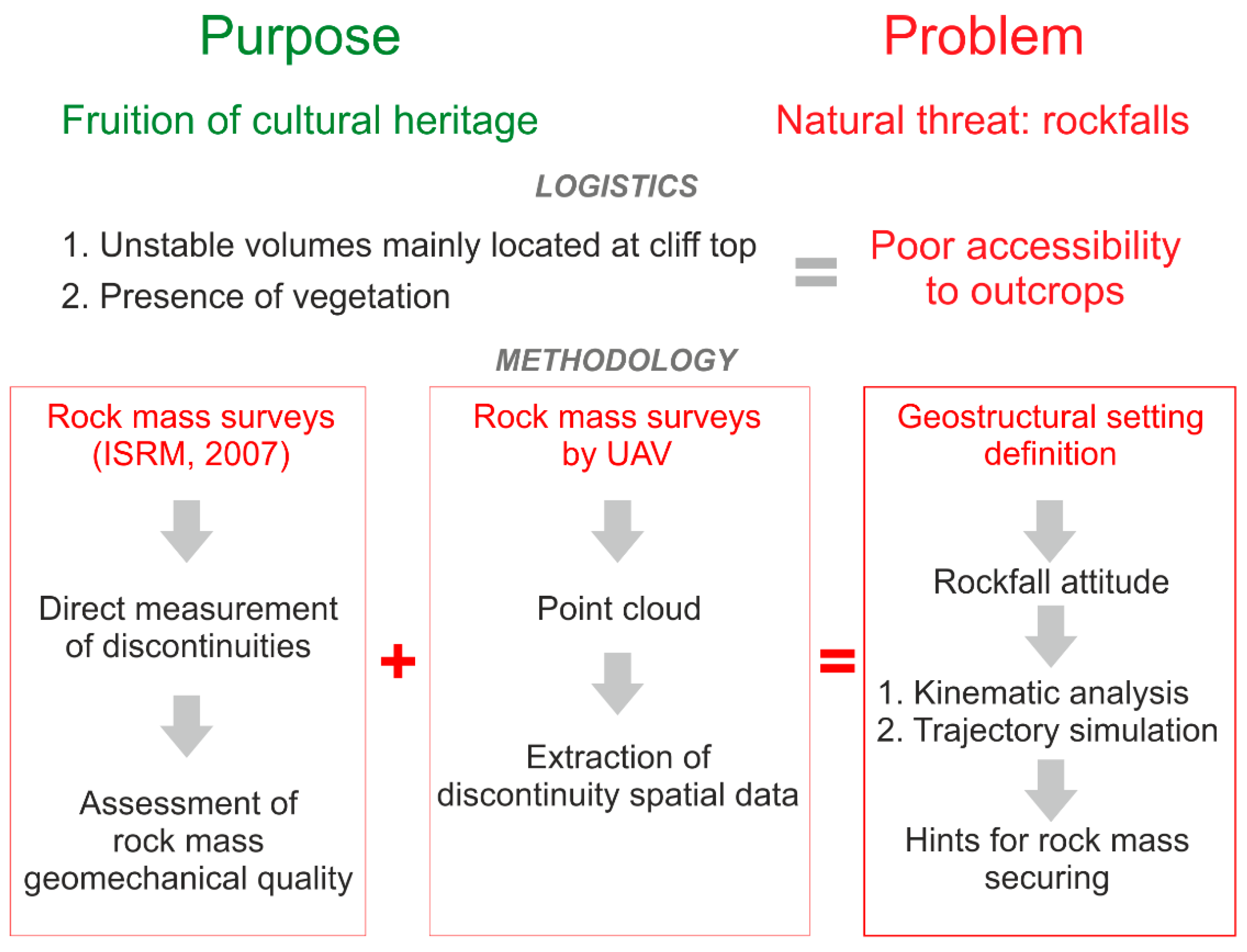
The main difficulty in modeling the geomechanical condition of the Monte Tauro cliff is that most of the loose rock volumes are located at the highest elevations, which cannot be directly reached by an operator for a survey even due to the presence of vegetation enhancing the poor ground accessibility of some outcrops. To overcome this limitation, ground rock mass surveys were performed at representative outcrops located along the access path and were integrated by aerial surveys performed by UAV aimed at providing a closer view of the rock condition and at extracting dip-direction data of the most recurring discontinuity sets along different fronts (Figure 2). In particular, the ground geostructural characterization was carried out by traditional rock mass surveys performed according to the International Society for Rock Mechanics (ISRM) [47] specifications. The orientation of discontinuities was statistically analyzed, and dip-immersion data were grouped into different sets according to the concentration of poles. For each system, the main geomechanical parameters (i.e., persistence, spacing, opening, in-filling, Joint Roughness Coefficient JRC, uniaxial compressive strength UCS, hydraulic conditions) have been measured and the geomechanical Rock Mass Rating (RMR) and Slope Mass Rating (SMR) classifications [48,49] were applied to assess the rock mass quality and to have general information on the need and type of mitigation measures (Figure 2).
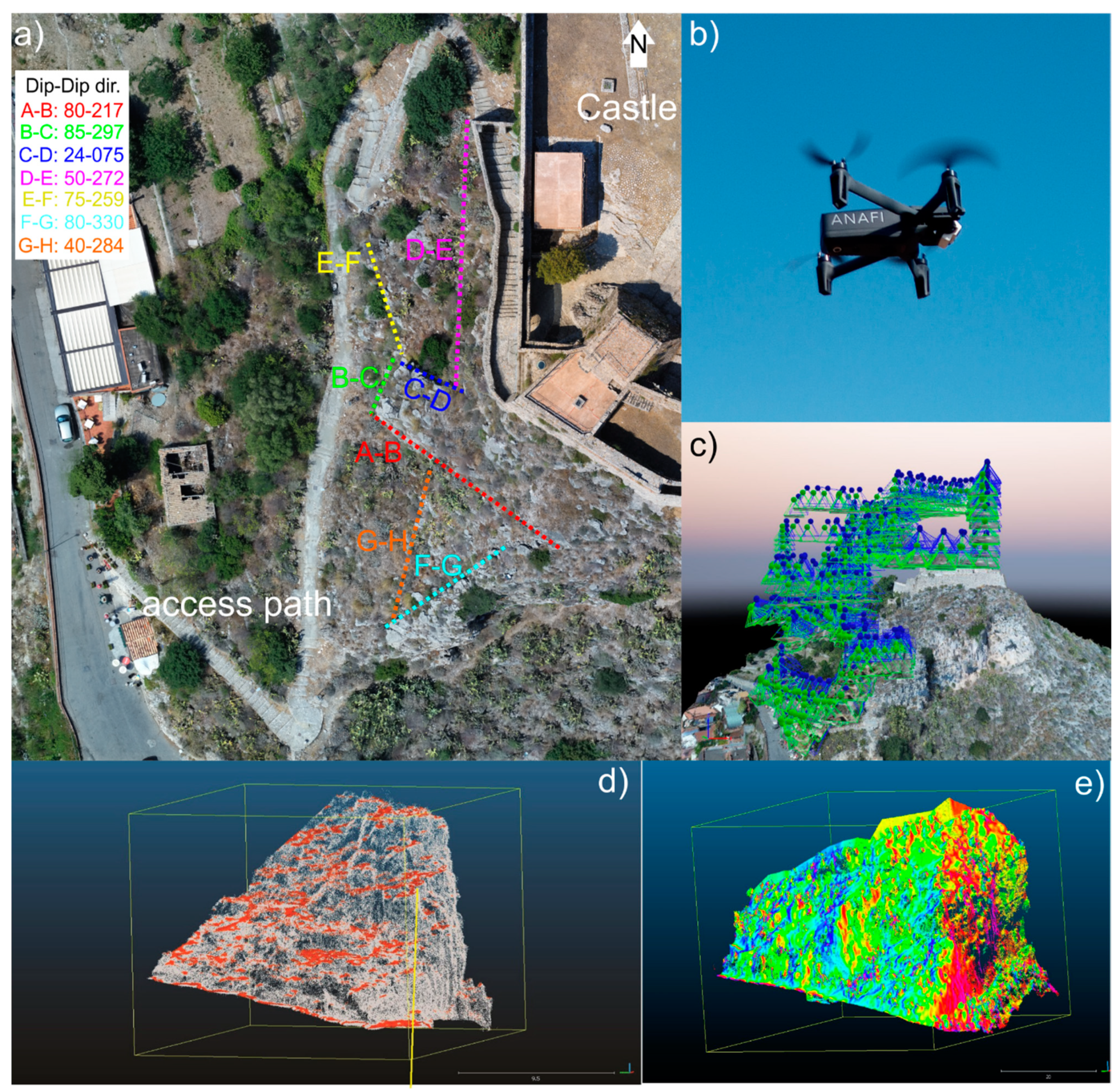
The use of an UAV allowed overcoming also the limitation of the irregular slope geometry, characterized by seven different slope faces and hosting most of the unstable rock volumes at its top, i.e., impossible access for a ground operator (Figure 3a). The employed vehicle was equipped with a 21 Mp HDR camera with a 3-Axis Gimbal Stabilizer (Figure 3b). Six 50 cm × 50 cm targets were placed as Ground Control Points (GCP) at fixed spots homogeneously distributed within the study area for a precise GPS localization and two flight plans were set. The first one was aimed at achieving a global view of the study area and was carried out in nadir condition, i.e., the image frames are shot by holding the camera axis aligned with the vertical direction, with a Ground Sample Distance between 1 and 2 cm (each pixel encloses a 1 to 4 cm2 area) and an average flight altitude of 25 m, guaranteeing a lateral overlap of at least 90% and a vertical overlap of 70% between the contiguous frames. The second flight plan was set according to the orientation of the seven slope faces and was carried out through frontal and oblique shots (45°) (Figure 3c), which allows a good integration for the accurate 3D reconstruction [50]. Fixed targets were also selected on the ground as Quality Control Points to assess the absolute accuracy of the resulting model. Data georeferencing was carried out by entering the UTM-ETRF2000-RDN coordinates acquired by topographic survey for each GCP. Such procedure allowed the georeferencing and scaling of all the models, achieving high accuracy and minimizing the georeferencing error (1–2 cm). Since the flight mission was planned with a 1 cm Ground Sampling Distance, the verified accuracy was around 1.5–3.0 cm.
Acquired images were equalized for the white balancing, aligned and georeferenced, in order to build a dense point cloud, with a final point spacing of 0.7 cm. The dense clouds, processed by the Pix4D photogrammetric software, were processed by further algorithms, in order to reconstruct accurate triangulated 3d models (3d mesh). These algorithms allow to operate a further noise reduction through the statistical removal of anomalous points (outliers) resulting from errors of homologous points. Similarly, points related to objects not pertinent to the purpose of the survey have been selected and removed (aerial cables, pylons, vegetation around the area, etc.). Dense point clouds were then interpolated by applying the Poisson algorithm for the reconstruction of the 3d mesh. Before the extrapolation of the 3D model, the processing parameters of the photogrammetric datasets were verified, edited and normalized. Once it was ascertained that all the information was consistent, and that the general post-processing phases had produced the complete geoDataBase for the definition and coverage of the area, input data were re-checked to ensure the reliability of results. Discontinuity data orientation were extracted from the point cloud by analyzing the normal vector associated to the single points through the open-source software CloudCompare. According to this procedure, by assigning a color to each similar orientation, planes with a similar spatial orientation were highlighted (Figure 3d,e).
Spatial discontinuity data arising from both the surveying methodologies were firstly compared and then integrated, achieving a representative cumulative stereonet showing the kinematic asset of recognized discontinuity sets. This was employed for a kinematic analysis, aimed at highlighting the main unstable patterns. Moreover, with the aim of finding out the impact that a falling block would have on the access path and neighboring areas, rockfall potential trajectory were simulated on a 3D cliff model, generated from a Digital Terrain Model (DTM) with a 2 m regular grid of the study area, which was provided for scientific purposes by Assessorato Territorio e Ambiente of Regione Siciliana (Figure 2). Blocks simulated for this study were released from established “launch sites” located at the surveyed unstable rock faces by the Georock 3D computer program [51]. Volumes range from 0.15 to 1 m3 in accordance with the most recurring unstable block configurations surveyed in the area. Such blocks were assumed as spheres rotating around their gravity center producing multiple impacts on the elevation-attributed plane represented by a grid of tridimensional nodes forming a triangular mesh. The energy exchanged between the falling rock and the slope has been modeled through coefficients of restitution (Table 1), in their normal and tangential components, which were claimed by the recent literature on neighboring areas [14,41,43,46].

4. Results

4.1. Rock Mass Surveys

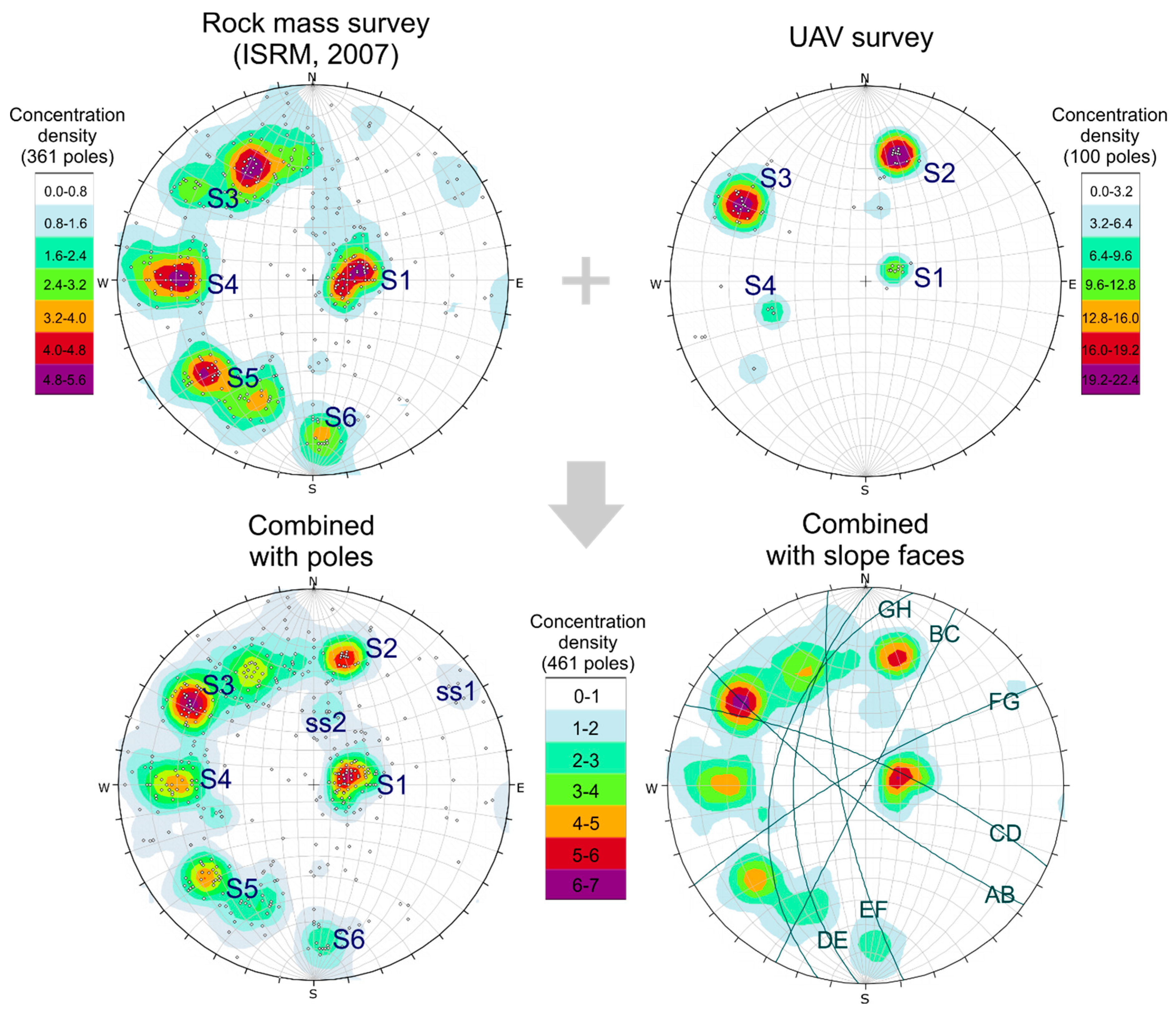
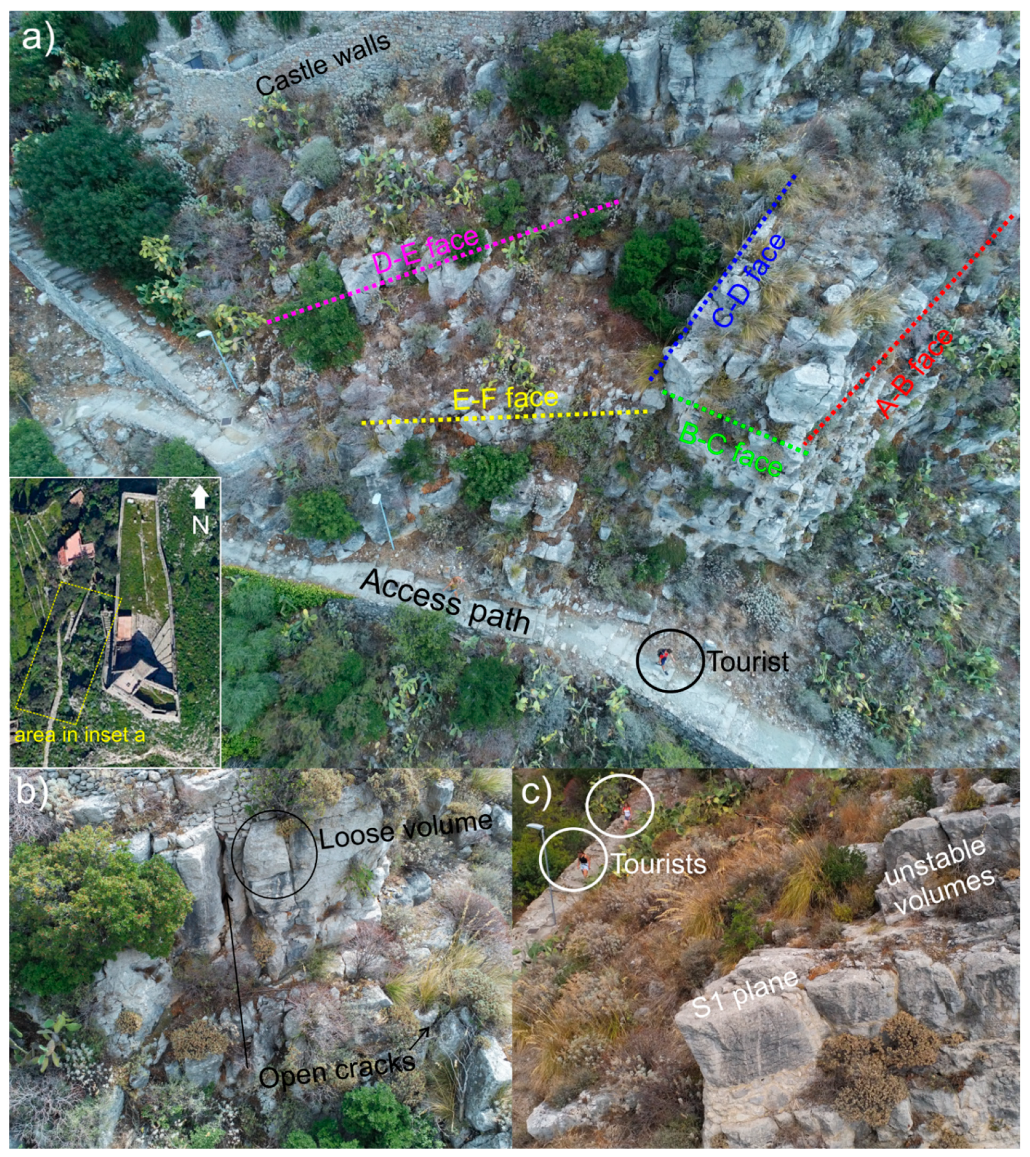
The ground rock mass survey highlighted that discontinuities are characterized by a close-to-wide spacing and variable aperture values (from tight to moderate) (Figure 4a–c). In particular, there are several spots where rock volumes are isolated, and loose blocks with a very poor connection with the rock mass (Figure 4d). The most open discontinuities are sometimes filled with hard or soft material, and the presence of widespread vegetation (plants and small shrubs) suggests a certain degree of water circulation, especially after heavy rains (Table 2). Such consideration supports the existence of instability features, also testified by blocks laying along the path (Figure 4e). Ground-surveyed discontinuities can be grouped into five main discontinuity systems according to the pole statistical contouring, which however returned wide pole concentration areas (Figure 5). This suggests a certain variability in the orientation of discontinuity planes, thus a large spectrum of potential kinematic configurations. Moreover, several scattered poles occur in the stereonet, which will not be neglected in the kinematic analysis although these were not been grouped into a specific set due to the lower density of pole occurrence. Based on the ISRM [47] survey, the application of the Rock Mass Rating (RMR) system [43] returned a basic RMR score ranging from 47 to 56 corresponding to a “fair” rock mass quality (Table 2). The Slope Mass Rating (SMR) classification [49], involving also the spatial relationship between discontinuities and slope, returned values ranging between 53 and 62, averagely corresponding to a “fair” geomechanical quality, with instability mainly occurring along planes and requiring systematic stabilization works.
The UAV survey covered the whole height of the cliff siding the access road to the castle (Figure 6a) and overcoming the limitation arising from the cliff height. It allowed surveying of the presence of open cracks defining irregular blocks laying on a generally dip-slope plane (Figure 6b,c). The latter can be regarded as a bedding surface, due to its constant occurrence at different heights and with different spacing values. Furthermore, vegetation occurs within open fractures (Figure 6), testifying the presence of water circulation within the rock mass even if mainly after heavy rainfalls, and representing a predisposing factor to the instability [52,53,54]. The resulting stereonet reports four main pole concentration areas, referred to four identified discontinuity systems (Figure 5).
By comparing spatial data of discontinuity surveyed both on ground and from air, some differences can be highlighted. The first and most evident one is the number of poles, which is sensibly lower and with a narrower statistical contouring in the UAV stereogram (Figure 5). This depends on the way the survey is carried out: in the traditional rock mass survey, the operator can operate according to either an objective or a subjective criterion. In the first case, all the discontinuities falling within a window or crossed by a scanline should be surveyed. This leads to a greater amount of field data. On the contrary, data arising from UAV are related only to those planes that effectively can be “seen” by the aerial vehicle, thus excluding the surfaces covered by vegetation for example. Moreover, an operator can measure the dip-immersion of not well-exposed discontinuities (e.g., lines of crack in the rock mass), contrary to an UAV.
Besides the number of poles, which is a matter of number of surveys, a further difference refers to the reliability of data. By comparing the two stereograms it is evident that S5 and S6 discontinuity systems are missing in the UAV output. Similarly, the S2 set is not well marked in the rock mass survey stereogram, although some poles can be referred to this family. By combining the two data sets, a unique stereogram was obtained, with the evidence of six main discontinuity sets, along with a relevant number of scattered poles (Figure 5). The latter could not be grouped into “main” systems due to a poor statistical contouring, but they are index of a complex geostructural setting of the rock cliff. In this case, the most significant two “secondary” clusters were labeled as ss1 and ss2.
From the kinematic point of view, by taking into account all the poles failing both within and outside the set clusters (Table 3), the most recurring pattern is toppling failure, in both its direct and flexural configuration. In particular, toppling mainly occurs along S1 set, representing a base plane for blocks and acting as a release surface for their toppling. S1 set is also a sliding plane for planar sliding failures; therefore, this can be referred to as the most kinematically critical discontinuity system. Planar sliding also affects the S2 and S5 planes when the slope face is NW-SE oriented. Wedge failures mainly occur along two intersecting discontinuities, in both symmetrical and asymmetrical configurations, involving also the secondary ss1 and ss2 clusters. Random planes are involved in all the unstable kinematic failure modes, due to their recurrence in the rock mass.

4.2. Rockfall Attitude

Rockfall trajectory simulations, carried out by considering established “launch sites” at the surveyed unstable rock faces, show that almost all the detached blocks would reach the access path, crossing it and moving downstream (Figure 7c–e). Block trajectories mainly follow the morphology of the cliff and the access path acts both as end point for most of the blocks and as a rebound plane for those proceeding downstream, with kinetic energies ranging between <5 and 350 kJ. The highest values were reached by the greatest simulated blocks detaching from the highest portions of rock slopes impending over the access path, while the lowest kinetic energies affect the southernmost path portion, where a ~180 m2 wide area hosting vegetation and shrubs lays between the unstable rock faces and the path itself. In fact, this low-angle area (profile AA’ in Figure 7c) plays a slowing action on blocks, stopping about 5% of total simulated ones. The remaining ones reaches and, sometimes, crosses the access path. On the other hand, when the rock cliff impends over the path (profile BB’ in Figure 7d), all the simulated boulders reach the access path, confirming the natural threat to the safe fruition of the place. A simulation also crossing the pedestrian path previously studied by [14] was reported herein (profile CC’ in Figure 7e) to prove the critical condition affecting the whole area hosting the cultural heritage.

5. Discussion and Conclusions

The rockfall analysis of the Taormina cliff, hosting an example of cultural heritage building, returned critical outcomes affecting the safe fruition of this tourist spot. The Saracen castle lays on the top of a carbonate cliff surrounded by several tourist attraction, e.g., a rock-hewn church, a panoramic viewpoint on the bay. The cliff is affected by widespread instability due to the fair rock mass geomechanical quality. The geostructural setting was herein evaluated by combining ground rock mass surveys and UAV surveys, which allowed the definition of a complete stereogram for the reliable reconstruction of the statistical spatial variability of discontinuities. A first discussion point is referred to the comparison between remote and ground rock mass data, which gains a broad scientific relevance. The combination of data resulting from UAV and ground surveys allowed achieving a complete geostructural scenario affecting the cliff, where most of the unstable features are located at the top portions, i.e., not directly reachable by a ground operator. More specifically, the two survey methodologies proved complementary. In fact, the ISRM [47] survey allowed measuring a greater number of discontinuities, leading to the definition of multiple pole clusters in the discontinuity stereogram. Nevertheless, poles belonging to the S2 set were underestimated by the ground survey, probably due to the low extension of surveyable ground outcrops and to their bad accessibility. On the other hand, the UAV survey returned a sensibly lower number of poles and some set surveyed on ground were missing. Such difference arises from the fact that the two techniques are based on different field procedures and are affected by both strength and weakness points: on the one hand, direct rock mass surveys allow the recognition of all the discontinuity systems along a scanline or within a survey window, especially if carried out according to objective approaches, including low-persistent cracks and close crack traces on the rock face; this approach is however limited by the accessibility of outcrops (i.e., high cliff sectors, intensely vegetated slope portions). On the other hand, UAV outcomes are conditioned by the availability of exposed planes along the rock face, which are those planes directly “seen” by the camera, and by their orientation; nevertheless, it allows the survey and the close viewing of rock mass sectors laying out of the reach of a ground operator, providing key data especially where the main instability features are located at the top of rock masses. A separate consideration must be reported with reference to the location of UAV surveys, as the employment of unmanned aerial vehicle is subject to local regulations involving its weight and the complexity of operations, especially when flying over urban centers or densely populated areas. Furthermore, the meteorological conditions strongly affect the use of UAVs, thus representing a limitation, especially in windy areas or under adverse weather circumstances. Such considerations are scientifically significant with reference to the current state of the art on the rock mass surveys, because the technological progress often leads to innovative procedures, which underestimate the utility of traditional approaches. In this specific case, for example, a stand-alone UAV survey would have provided incomplete geostructural data, which would have not ensured a reliable kinematic analysis. Similarly, the ground rock mass survey gains more reliability if supported by UAV, especially for the highest cliff sectors.
With reference to the sustainable fruition of the cultural heritage analyzed herein, the integration of field data allowed performing a complete kinematic analysis based on the seven different orientations of slope faces. Due to the abrupt variations of the rock face direction, almost all the discontinuity systems are responsible to unstable kinematic configurations, from toppling to planar and wedge sliding. In particular, the most recurring failure patterns are toppling and planar sliding, both enhanced by the presence of a low-angle discontinuity plane daylighting out of the rock face and releasing blocks towards the main element at risk, i.e., the pedestrian access path to the castle. This outcome, along with the visible setting of loose blocks laying on such planes, is index of the tangible threat that rockfalls represent for the access path to the castle, where several already fallen blocks lay. Furthermore, the rockfall trajectory simulations ascertained that most of the detaching blocks would reach and, sometimes, cross the access path. The highest kinetic energies are likely reached in those sectors where the rock mass impends over the path, which would act as the first target of blocks, while lower energies are likely reached where vegetated sectors are interposed between the rock mass and the path.
According to achieved outcomes, it is self-evident that the securing of this area is not a simple subject. A combination measures should be evaluated in order to protect the wide rock slopes, affected by abrupt orientation variations. More specifically, the scaling with consequently removal of isolated blocks can be a potential useful solution for the isolated volumes, especially those impending over the path. This activity is however conditioned by the accessibility to working means. For the greatest unstable volumes, local anchors could be a suitable solution, whose potential efficiency should be evaluated by specialized climbers rock mass surveyors. Nevertheless, due to the great number of loose rocks, rockfall netting seems a proper remedial work. In particular, it would be preferrable the installation of double-layer wire meshes fixed to the rock mass by anchors crossing the most external, loose rock mass portion. Such double-layer wire meshes would be useful to retain even the smaller rock volumes, thus preventing rocks and debris from falling onto the access path, especially at the northern slope faces B-C, E-F and D-E, impending over the path. At A-B, G-H, F-G fronts, the installation of an anchored single-layer wire mesh could be evaluated as an alternative, thanks to the vegetated spot interposed between slope and path, which could stop the smaller rock volumes, although the slowing action played by vegetation on falling blocks can be reduced in case of fire.

Author Contributions

Conceptualization, methodology, supervision: S.M. and G.P. Field investigation, data curation, writing and review: S.M., G.P. and S.O. All authors have read and agreed to the published version of the manuscript.

Funding

This research was financially supported by “CH2V—Cultural Heritage Hazard and Vulnerability” project, scientific responsible Giovanna Pappalardo.

Informed Consent Statement

Not applicable.

Data Availability Statement

Not applicable.

Acknowledgments

Rock mass data were analyzed and processed at the “Geologia Applicata” laboratory of Department of Biological, Geological and Environmental Sciences, Catania University.

Conflicts of Interest

The authors declare no conflict of interest.

References

  1. Canuti, P.; Casagli, N.; Fanti, R.; Iotti, A.; Pecchioni, E.; Santo, A.P. Rock weathering and failure of the “Tomba della Sirena” in the Etruscan necropolis of Sovana (Italy). J. Cult. Herit. 2004, 5, 323–330. [Google Scholar] [CrossRef]
  2. Canuti, P.; Margottini, C.; Fanti, R.; Bromhead, E.N. Cultural Heritage and Landslides: Research for Risk Prevention and Conservation. In Landslides—Disaster Risk Reduction; Sassa, K., Canuti, P., Eds.; Springer: Berlin, Germany, 2009; pp. 401–433. [Google Scholar] [CrossRef]
  3. Lollino, G.; Audisio, C. UNESCO World Heritage sites in Italy affected by geological problems, specifically landslide and flood hazard. Landslides 2006, 3, 311–321. [Google Scholar]
  4. Roberts, N. Canada Culture and landslide risk in the Central Andes of Bolivia and Peru. Stud. Univ. Babes Bolyai Geol. 2009, 54, 55–59. [Google Scholar] [CrossRef] [Green Version]
  5. Fanti, R.; Gigli, G.; Lombardi, L.; Tapete, D.; Canuti, P. Terrestrial laser scanning for rockfall stability analysis in the cultural heritage site of Pitigliano (Italy). Landslides 2012, 10, 409–420. [Google Scholar] [CrossRef] [Green Version]
  6. Tarragüel, A.A.; Krol, B.; Van Westen, C. Analysing the possible impact of landslides and avalanches on cultural heritage in Upper Svaneti, Georgia. J. Cult. Heritage 2012, 13, 453–461. [Google Scholar] [CrossRef]
  7. Pappalardo, G.; Imposa, S.; Mineo, S.; Grassi, S. Evaluation of the stability of a rock cliff by means of geophysical and geomechanical surveys in a cultural heritage site (south-eastern Sicily). Ital. J. Geosci. 2016, 135, 308–323. [Google Scholar] [CrossRef]
  8. Pappalardo, G.; Imposa, S.; Barbano, M.S.; Grassi, S.; Mineo, S. Study of landslides at the archaeological site of Abakainon necropolis (NE Sicily) by geomorphological and geophysical investigations. Landslides 2018, 15, 1279–1297. [Google Scholar] [CrossRef]
  9. Bunce, C.M.; Cruden, D.M.; Morgenstern, N.R. Assessment of the hazard from rockfall on a highway. Can. Geotech. J. 1997, 34, 344–356. [Google Scholar]
  10. Evans, S.; Hungr, O. The assessment of rockfall hazard at the base of talus slopes. Can. Geotech. J. 1993, 30, 620–636. [Google Scholar] [CrossRef]
  11. Pierson, L.A.; Davis, S.A.; Van Vickle, R. Rockfall Hazard Rating System—Implementation Manual, Federal Highway Administration (FHWA); Report FHWAOR- EG-90–01; FHWA, US Department of Transportation: Washington, DC, USA, 1990.
  12. Briones-Bitar, J.; Carrión-Mero, P.; Montalván-Burbano, N.; Morante-Carballo, F. Rockfall Research: A Bibliometric Anal-ysis and Future Trends. Geosciences 2020, 10, 403. [Google Scholar]
  13. Scavia, C.; Barbero, M.; Castelli, M.; Marchelli, M.; Peila, D.; Torsello, G.; Vallero, G. Evaluating Rockfall Risk: Some Critical Aspects. Geosciences 2020, 10, 98. [Google Scholar] [CrossRef] [Green Version]
  14. Mineo, S.; Pappalardo, G.; Mangiameli, M.; Campolo, S.; Mussumeci, G. Rockfall Analysis for Preliminary Hazard Assessment of the Cliff of Taormina Saracen Castle (Sicily). Sustainability 2018, 10, 417. [Google Scholar] [CrossRef] [Green Version]
  15. Mineo, S.; Pappalardo, G. Sustainable Fruition of Cultural Heritage in Areas Affected by Rockfalls. Sustainability 2020, 12, 296. [Google Scholar] [CrossRef] [Green Version]
  16. Glade, D. Unmanned Aerial Vehicles: Implications for Military Operations; Air University Maxwell Air Force Base: Montgomery, AL, USA, 2000. [Google Scholar]
  17. Chiabrando, F.; Lingua, A.; Rinaudo, F.; Spanò, A. Archaeological site monitoring: UAV photogrammetry could be an answer. In Proceedings of the International Archives of Photogrammetry, Remote Sensing and Spatial Information Sciences, Melbourne, VIC, Australia, 25 August–1 September 2012. [Google Scholar]
  18. Piras, M.; Taddia, G.; Forno, M.G.; Gattiglio, M.; Aicardi, I.; Paolo, D.; Russo, S.L.; Maria, L.A. Detailed geological mapping in mountain areas using an unmanned aerial vehicle: Application to the Rodoretto Valley, NW Italian Alps. Geomat. Nat. Hazards Risk 2016, 8, 137–149. [Google Scholar] [CrossRef]
  19. Coifman, B.; Mccord, M.; Mishalani, R.G.; Iswalt, M.; Ji, Y. Roadway traffic monitoring from an unmanned aerial vehicle. IEE Proc. Intell. Transp. Syst. 2006, 153, 11. [Google Scholar] [CrossRef] [Green Version]
  20. Karantanellis, E.; Marinos, V.; Vassilakis, E.; Christaras, B. Object-Based Analysis Using Unmanned Aerial Vehicles (UAVs) for Site-Specific Landslide Assessment. Remote Sens. 2020, 12, 1711. [Google Scholar] [CrossRef]
  21. Sarro, R.; Riquelme, A.; López-Davalillo, J.C.G.; Mateos, R.M.; Tomás, R.; Pastor, J.L.; Gonzalez, M.C.; Herrera, G. Rockfall Simulation Based on UAV Photogrammetry Data Obtained during an Emergency Declaration: Application at a Cultural Heritage Site. Remote Sens. 2018, 10, 1923. [Google Scholar] [CrossRef] [Green Version]
  22. Francioni, M.; Simone, M.; Stead, D.; Nicola, S.; Mataloni, G.; Calamita, F. A New Fast and Low-Cost Photogrammetry Method for the Engineering Characterization of Rock Slopes. Remote Sens. 2019, 11, 1267. [Google Scholar] [CrossRef] [Green Version]
  23. Nex, F.; Remondino, F. UAV for 3D mapping applications: A review. Appl. Geomat. 2014, 6, 1–15. [Google Scholar] [CrossRef]
  24. Vacca, G.; Dessì, A.; Sacco, A. The Use of Nadir and Oblique UAV Images for Building Knowledge. ISPRS Int. J. Geo Inf. 2017, 6, 393. [Google Scholar] [CrossRef] [Green Version]
  25. Greenwood, W.; Zekkos, D.; Lynch, J.; Bateman, J.; Clark, M.K.; Chamlagain, D. UAV-Based 3-D Characterization of Rock Masses and Rock Slides in Nepal. In Proceedings of the 50th ARMA U.S. Rock Mechanics/Geomechanics Symposium, Houston, TX, USA, 26–29 June 2016; pp. 16–678. [Google Scholar]
  26. Brückl, E.; Brunner, F.K.; Kraus, K. Kinematics of a deep-seated landslide derived from photogrammetric, GPS and geo-physical data. Eng. Geol. 2006, 88, 149–159. [Google Scholar]
  27. Collins, B.D.; Stock, G.M. Lidar-Based Rock-Fall Hazard Characterization of Cliffs. In GeoCongress 2012: State of the Art and Practice in Geotechnical Engineering, Proceedings of GeoCongress 2012, Oakland, CA, USA, 25–29 March 2012; Hryciw, R.D., Athanasopoulos-Zekkos, A., Yesiller, N., Eds.; American Society of Civil Engineers: Reston, VA, USA, 2012; pp. 3021–3030. [Google Scholar] [CrossRef] [Green Version]
  28. Vöge, M.; Lato, M.J.; Diederichs, M.S. Automated rockmass discontinuity mapping from 3-dimensional surface data. Eng. Geol. 2013, 164, 155–162. [Google Scholar] [CrossRef]
  29. Gigli, G.; Casagli, N. Semi-automatic extraction of rock mass structural data from high resolution LIDAR point clouds. Int. J. Rock Mech. Min. Sci. 2011, 48, 187–198. [Google Scholar] [CrossRef]
  30. Sturzenegger, M.; Stead, D. Quantifying discontinuity orientation and persistence on high mountain rock slopes and large landslides using terrestrial remote sensing techniques. Nat. Hazards Earth Syst. Sci. 2009, 9, 267–287. [Google Scholar] [CrossRef]
  31. Riquelme, A.J.; Abellán, A.; Tomás, R. Discontinuity spacing analysis in rock masses using 3D point clouds. Eng. Geol. 2015, 195, 185–195. [Google Scholar] [CrossRef] [Green Version]
  32. Mancini, F.; Castagnetti, C.; Rossi, P.; Dubbini, M.; Fazio, N.; Perrotti, M.; Allasia, P. An Integrated Procedure to Assess the Stability of Coastal Rocky Cliffs: From UAV Close-Range Photogrammetry to Geomechanical Finite Element Modeling. Remote Sens. 2017, 9, 1235. [Google Scholar] [CrossRef] [Green Version]
  33. Salvini, R.; Mastrorocco, G.; Seddaiu, M.; Rossi, D.; Vanneschi, C. The use of an unmanned aerial vehicle for fracture mapping within a marble quarry (Carrara, Italy): Photogrammetry and discrete fracture network modelling. Geomatics, Nat. Hazards Risk 2017, 8, 34–52. [Google Scholar] [CrossRef]
  34. Danzi, M.; Di Crescenzo, G.; Ramondini, M.; Santo, A. Use of unmanned aerial vehicles (UAVs) for photogrammetric surveys in rockfall instability studies. Rendiconti Online Societa Geologica Italiana 2013, 24–82, 85. [Google Scholar]
  35. Loiotine, L.; Liso, I.S.; Parise, M.; Andriani, G.F. Optimization of Geostructural Surveys In Rock Mass Stability Analyses Using Remote Sensing Techniques. Ital. J. Eng. Geol. Environ. 2019, 73–78, Special Issue 1. [Google Scholar] [CrossRef]
  36. Robiati, C.; Eyre, M.; Vanneschi, C.; Francioni, M.; Venn, A.; Coggan, J. Application of Remote Sensing Data for Evaluation of Rockfall Potential within a Quarry Slope. ISPRS Int. J. Geo Inf. 2019, 8, 367. [Google Scholar] [CrossRef] [Green Version]
  37. Rodriguez, J.; Macciotta, R.; Hendry, M.T.; Roustaei, M.; Gräpel, C.; Skirrow, R. UAVs for monitoring, investigation, and mitigation design of a rock slope with multiple failure mechanisms—A case study. Landslides 2020, 17, 2027–2040. [Google Scholar] [CrossRef]
  38. Argeri, G. Storia di San Piero Patti: Attraverso gli Avvenimenti più Importanti della Sicilia; Scuola Grafica Salesiana: Palermo, Italy, 1984. [Google Scholar]
  39. Lentini, F.; Carbone, S.; Guarnieri, P. Collisional and postcollisional tectonics of the Apenninic-Maghrebian orogen (southern Italy). In Geological Society of America Special Paper 409; Geological Society of America: Boulder, CO, USA, 2006; pp. 57–81. [Google Scholar]
  40. Ferrara, V.; Pappalardo, G. Kinematic analysis of rock falls in an urban area: The case of Castelmola hill near Taormina (Sicily, Italy). Geomorphology 2005, 66, 373–383. [Google Scholar] [CrossRef]
  41. Mineo, S.; Pappalardo, G.; D’Urso, A.; Calcaterra, D. Event tree analysis for rockfall risk assessment along a strategic mountainous transportation route. Environ. Earth Sci. 2017, 76, 620. [Google Scholar] [CrossRef] [Green Version]
  42. Mineo, S. Comparing rockfall hazard and risk assessment procedures along roads for different planning purposes. J. Mt. Sci. 2020, 17, 653–669. [Google Scholar] [CrossRef]
  43. Pappalardo, G.; Mineo, S.; Rapisarda, F. Rockfall hazard assessment along a road on the Peloritani Mountains (northeastern Sicily, Italy). Nat. Hazards Earth Syst. Sci. 2014, 14, 2735–2748. [Google Scholar] [CrossRef] [Green Version]
  44. Pappalardo, G.; Mineo, S.; Zampelli, S.P.; Cubito, A.; Calcaterra, D. InfraRed Thermography proposed for the estimation of the Cooling Rate Index in the remote survey of rock masses. Int. J. Rock Mech. Min. Sci. 2016, 83, 182–196. [Google Scholar] [CrossRef]
  45. Pappalardo, G.; Mineo, S.; Calcaterra, D. Geomechanical Analysis of Unstable RockWedges by Means of Geostructural and Infrared Thermography Surveys. Ital. J. Eng. Geol. Environ. 2017, 93–101. [Google Scholar] [CrossRef]
  46. Pappalardo, G.; Mineo, S. Rockfall Hazard and Risk Assessment: The Promontory of the Pre-Hellenic Village Castelmola Case, North-Eastern Sicily (Italy). In Engineering Geology for Society and Territory—Volume 2; Lollino, G., Manconi, A., Clague, J., Shan, W., Chiarle, M., Eds.; Springer International Publishing: Cham, Switzerland, 2015; Volume 2, pp. 1989–1993. [Google Scholar] [CrossRef]
  47. International Society for Rock Mechanics (ISRM). The complete ISRM suggested methods for rock characterization, testing and monitoring: 1974–2006. In Suggested Methods Prepared by the Commission on Testing Methods; Ulusay, R., Hudson, J.A., Eds.; Compilation Arranged by the ISRM Turkish National Group; International Society for Rock Mechanics: Ankara, Turkey, 2007; p. 628. [Google Scholar]
  48. Bieniawski, Z.T. Engineering Rock Mass Classification; John Wiley & Son: New York, NY, USA, 1989; p. 251. [Google Scholar]
  49. Romana, M. SMR Classification. In Proceedings of the 7th International Congress on Rock Mechanics, Aachen, Germany, September 1991; Balkema: Rotterdam, The Netherlands, 1991; pp. 955–960. [Google Scholar]
  50. Koeva, M.; Muneza, M.; Gevaert, C.; Gerke, M.; Nex, F. Using UAVs for map creation and updating. A case study in Rwanda. Surv. Rev. 2016, 1–14. [Google Scholar] [CrossRef] [Green Version]
  51. Geostru. Georock 3D User Manual; Geostru: Cluj-Napoca, Romania, 2013. [Google Scholar]
  52. Ansari, M.K.; Ahmed, M.; Singh, R.; Singh, T.N.; Ghalayani, I. Rainfall, A Major Cause for Rockfall Hazard along the Roadways, Highways and Railways on Hilly Terrains in India. In Engineering Geology for Society and Territory; Lollino, G., Manconi, A., Clague, J., Shan, W., Chiarle, M., Eds.; Springer: Cham, Switzerland, 2015; Volume 1. [Google Scholar] [CrossRef]
  53. Barbano, M.S.; Pappalardo, G.; Pirrotta, C.; Mineo, S. Landslide triggers along volcanic rock slopes in eastern Sicily (Italy). Nat. Hazards 2014, 73, 1587–1607. [Google Scholar] [CrossRef]
  54. Melillo, M.; Gariano, S.L.; Peruccacci, S.; Sarro, R.; Mateos, R.M.; Brunetti, M.T. Rainfall and rockfalls in the Canary Islands: Assessing a seasonal link. Nat. Hazards Earth Syst. Sci. 2020, 20, 2307–2317. [Google Scholar] [CrossRef]
Figure 1. (a) Panoramic view of the Saracen Castle area (photo from Wikipedia); (b) satellite image of the study area with location of the main elements: 1. Saracen castle, 2. access path, 3. unstable rock masses, 4. viewpoint, 5. rock-hewn church, 6. pedestrian path to the city center; (c) geological schematic map of the Taormina area (modified by [14]); (d) the main elements at risk seen from the top of the top of the cliff.
Sustainability 13 00924 g001
Figure 2. Conceptual map on the purpose and methodology of this research.
Sustainability 13 00924 g002
Figure 3. (a) UAV surveyed area with indication of the different slope faces (differently colored lines trace the slope face); (b) photo of the employed UAV; (c) traces of oblique shots; (d) example of cloud point of B-C front with highlighted the sub-horizontal planes; (e) dip-immersion radiometric values in scalar field of the whole cliff.
Sustainability 13 00924 g003
Figure 4. Representative rock masses surveyed by ground; (a) location of the shots reported in insets, (b) scanline and evident dip-slope bedding plane, (c) discontinuity showing a wide aperture, (d) loose blocks and vegetated spots, (e) block fallen and stopped along the access path.
Sustainability 13 00924 g004
Figure 5. Stereographic projections of surveyed data shown both with reference to the survey mode and in combined version with poles and great circles of surveyed slope faces.
Sustainability 13 00924 g005
Figure 6. Representative photos from UAV: (a) slope faces with visible loose rock volumes impending over the access path; (b) open cracks isolating rock volumes; (c) a close image of the dip-slope plane enhancing planar sliding over the access path crossed by tourists.
Sustainability 13 00924 g006
Figure 7. Simulated rockfall trajectories crossing the main elements at risk. (a) 3D simulated trajectory, (b) trace of the simulations crossing the access path, (c) A-A’ profile simulation, (d) B-B’ profile simulation, (e) C-C’ profile simulation.
Sustainability 13 00924 g007
Table 1. Coefficients of restitutions employed for the rockfall simulations ([14] and references therein).
Cropping Out MaterialRtRn
Bare rock0.800.50
Rock talus + vegetation0.800.32
Rock debris0.650.15
Asphalt0.900.40
Table 2. Average input parameters used for RMR [48] and SMR [49] classifications.
Set
(Dip/Dip dir.)
Spacing (mm)Persistance (m)Aperture (mm)JRCInfillingWeatheringRMRb
Class
SMR
Class
S1
(22/261)
Close to ModerateVery highVery tight2–8noneSlight to Moderate47 to 56
III
53 to 62
III to II
S3
(68/135)
Close to ModerateHighModerate4–12softSlight to Moderate
S4
(69/088)
CloseMediumVery tight to Moderate4–10none/softSlight to Moderate
S5
(70/038)
ModerateMediumModerate14–16softModerate
S6
(76/357)
ModerateMediumModerate2–4softModerate
Table 3. Unstable kinematic pattern listed for each considered slope face and considering all the poles failing within a cluster. Key: P—planar sliding, W—wedge sliding, DT—direct toppling, FT—flexural toppling, r—random poles, I—intersection for direct toppling, BP—base plane for direct toppling.
Slope FaceUnstable Kinematic Pattern at Each Set
PWDTFT
ABS1, S2, ss2 rS1 to S4, S6, ss1, ss2, rS3 to S6, r (I)
S1, ss2, r (BP)
S5, r
BCS1, rS3, S5, S6, ss1, ss2, rS2 to S6, ss1, ss2, r (I)
S1, r (BP)
S3, S4, r
CDS5, rS1, S3 to S6, ss1, ss2, rS2 to S4, ss2, r (I)
S1, Se, r (BP)
S2, ss2, r
DES1, rS5, ss1, rS2 to S6, ss1, r (I)
S1, S5, r (BP)
S3, S4, r
EFS1, rS3, S5, S6, ss1, ss2, rS2 to S6, ss1, r(I)
S1, r (BP)
S4, S5, r
FGrS1, S2, S5, S6, ss1, rS2 to S5, ss1, ss2, r (I)
S1, S6, r (BP)
S3, r
GHS1, rS5, ss1, rS2 to S6, ss1, r (I)
S1, r (BP)
S3, S4, r
Publisher’s Note: MDPI stays neutral with regard to jurisdictional claims in published maps and institutional affiliations.