1. Introduction
Reactive power has been a well-known quantity in the technical literature since Stanley [
1], Schallenberger [
2], and Steinmetz [
3] physically and mathematically explained this phenomenon in single-phase sinusoidal systems in the late 19th century. The formulation and physical meaning of reactive power have been extensively studied throughout the 20th century [
4,
5,
6,
7], and even today [
8,
9]. The IEEE Standard 1459 [
10] defines the reactive power as the fundamental frequency.
Likewise, this standard defines three reactive power components in three-phase, four-wire systems based on Fortescue’s contributions [
11,
12]. These reactive power components are the positive-, negative- and zero-sequence reactive powers in three-phase, four-wire systems. The scientific community has accepted the physical meanings of these reactive power components, which are actually included in the IEEE Standard 1459. The positive-sequence reactive power (
) is the most important reactive power component in power systems, much more than the zero-sequence reactive power (
). The negative-sequence reactive power (
) is usually negligible because of the limitations of the zero-sequence voltages below 1–2% imposed by the standards [
13,
14,
15,
16,
17,
18].
The interest in positive-sequence reactive powers is because these reactive power components determine the correct operation and stability of generators and motors in power systems, as the IEEE Standard 1459 establishes in its introduction. However, nowadays there are no passive devices for compensating separately from and . There are also no devices able to maintain the values of while the other two reactive power components’ resulting voltage imbalances ( and ) are cancelled. All compensation devices, passive and active, today known in the technical literature are used to compensate the total reactive power, i.e., they can cancel the three reactive power components (, , and ) at once, but these devices are not able to compensate for the reactive power components separately.
This is the case with capacitor banks used in most industrial applications. These passive devices minimize the total reactive power supplied by the sources, but they are not able to reduce significantly the reactive currents when supply voltages and loads are unbalanced, such as it will be noted in the application example and was theoretically demonstrated in [
19]. Since 2010, several passive reactive power compensators have been developed to operate in unbalanced voltage conditions [
20,
21,
22]. These devices compensate for the total reactive power in three-phase, four-wire power systems, while they also balance the active currents. Active devices for reactive power compensation are also well known in the technical literature, such as SVCs and STATCOMs [
23,
24,
25,
26,
27,
28,
29,
30,
31,
32,
33,
34,
35,
36,
37,
38]. The former is fundamentally dedicated to reactive power compensation, while the latter can also be applied to unbalanced compensation and, above all, harmonic filtering. These active devices are not the object of study in this paper, which is focused on passive reactive power compensators.
Due to the fact there are no passive devices in the technical literature for separately compensating each reactive power component (
,
, and
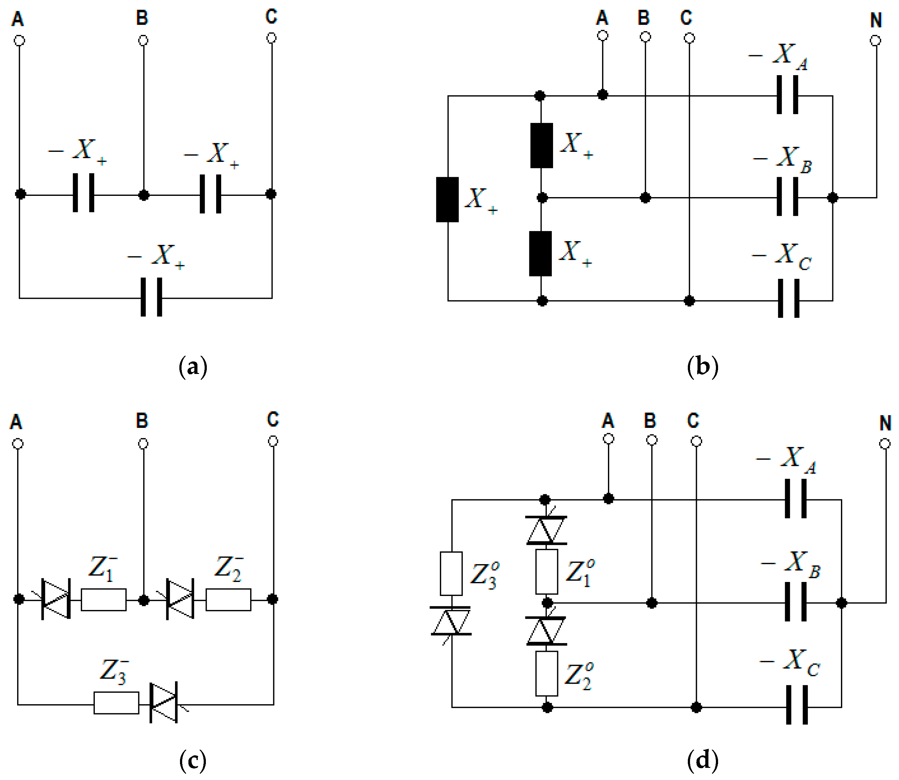
), the development of these passive compensators for three-phase, four-wire sinusoidal systems is the main novelty of this paper. Specifically, the following devices are theoretically developed in
Section 3 for three-phase, four-wire sinusoidal systems supplied by unbalanced voltages:
Individual compensators for the positive-sequence reactive powers (
Figure 1a), which minimize or cancel the supply of
without affecting the values of the other reactive power components (
and
).
Combined compensators for the negative- and zero-sequence reactive powers (
Figure 1b), which remove the supply of negative- and zero-sequence reactive powers (
) keeping invariable the values of positive-sequence reactive powers (
).
Individual compensators for the negative-sequence (
Figure 1c) and the zero-sequence (
Figure 1d) reactive powers, which respectively cancel
and
. The first individual devices do not modify the values of
and
, whereas the second individual compensators do not affect the values of
and
.
The individual compensators of positive-sequence reactive powers and the combined compensators are theoretically developed in
Section 3.2 and
Section 3.3.1, respectively. These devices are formed by passive reactances (coils and capacitors), as
Figure 1a,b represent, and they have important practical applications either minimizing the positive-sequence currents or removing the reactive currents caused by imbalances, respectively. These current reductions are useful to improve the sustainability of electrical networks by reducing power losses in transformers and lines.
Conversely, the individual compensators of negative- and zero-sequence reactive powers are less effective in reducing the reactive currents than the combined compensators listed above. Likewise, the phase impedances of these individual compensators have angles greater than ±90
and, thus, they are active devices because they must be formed by electronic converters (
Figure 1c,d) and, therefore, are more expensive than the combined compensators of
Figure 1b. These reasons justify the individual compensators of negative- and zero-sequence reactive powers being out of the title of this paper, which is focused in passive compensators. However, these active devices are theoretically developed in
Section 3.3.2. as an additional contribution of this paper and they are not practically implemented.
Topology and elements of all reactive power compensators mentioned above have been determined by applying Ohm’s law and Fortescue’s theorem [
11] under the consideration these devices must supply fundamental-frequency reactive currents of positive, negative and zero sequences. The use of Fortescue’s theorem is the key that determines topology differences between our compensators and the industrial capacitor banks, Jeon’s compensators, and similar passive devices described in [
21,
22]. Since Fortescue’s theorem is not applied to implement latter passive compensators, these can only compensate the total reactive powers, but they are not able to compensate separately each of the reactive power components.
Finally, in
Section 4, the operation of the reactive power passive compensators developed in this paper is tested in an application example on the actual unbalanced electrical installation of a manufacturer of frozen products. Likewise, the effectiveness of these passive devices on the sustainability improvement in the transformer and lines of that installation are been compared with those obtained from the capacitor banks and Jeon’s compensators [
20]. The comparison determines that:
The individual compensators for the positive-sequence reactive powers reduce energy source losses and carbon dioxide emissions caused by circulation of reactive currents in a similar amount as the traditional capacitor banks (60–80%).
The combined compensators of negative- and zero-sequence reactive powers cancel energy losses occurred in the neutral conductor, but they achieve modest reductions in source energy losses and carbon dioxide emissions due to circulation of reactive currents (20–40%).
The total reactive power compensators (TRPC) reduce 100% of energy source losses and carbon dioxide emissions caused by circulation of reactive currents, which is not possible with the capacitor banks today used in industrial applications.
2. Active and Reactive Power Components in Unbalanced Systems
In this section, the expressions for the positive-, negative-, and zero-sequence components of the active and reactive powers are established for the three-phase, four-wire sinusoidal and unbalanced system represented in
Figure 2 using Ohm’s and Kirchhoff’s laws and Fortescue’s theorem.
Considering that both the source and the load of the three-phase sinusoidal system in
Figure 2 are unbalanced, in general, and these subsystems are connected through lines and neutral wires of negligible impedances, the Complex Root Mean Square (CRMS) line (
) and neutral (
) currents
of this system are, according to Ohm’s and the first of Kirchhoff’s laws, as follows,
being the line-to-neutral voltages, the load complex admittances, expressed as a function of the load conductances () and susceptances (), and and are the active and reactive line currents of each phase , respectively.
Since voltages and currents of the system in
Figure 2 are generally unbalanced, these quantities can be decomposed into their positive- (
), negative- (
), and zero-sequence (
) components, according to Fortescue’s theorem [
11]. Thus, if the symmetrical components of the line-to-neutral voltages are
, the line currents can be decomposed as follows:
where
,
are the negative-sequence unbalance factor (
) and the zero-sequence unbalance factor (
) of the line-to-neutral voltages,
are the complex admittances for the positive-, negative-, and zero-sequences, expressed as a function of the respective conductances (
) and complex susceptances (
),
are the well-known complex admittance of the load supplied with positive-sequence voltages, and
are the ratios between voltages and currents of different sequences, which have dimensions of admittance and are defined in systems with both asymmetrical sources and loads.
The complex power supplied by the source and absorbed by the load of the system represented in
Figure 1 can be determined as a function of the line-to-neutral voltages and line currents,
where
and
are the active and complex reactive powers, respectively,
and the asterisk (*) denotes the conjugate of a complex quantity. The complex power can also be expressed as a function of the complex powers corresponding to each sequence as follows [
10]:
The real part of the complex power (
) is the active power (
) and the imaginary part is the reactive power (
),
where (
) and (
) are the well-known active and complex reactive powers, respectively defined in [
10] for the positive-, negative-, and zero-sequence voltages and currents.
2.1. Positive-Sequence Active and Reactive Powers
Positive-sequence active and reactive powers () are the main components of the complex power supplied by the generators in power plants and transferred through the high voltage (HV) lines as well as delivered in most low voltage (LV) distribution networks.
According to the first Equation (2), the positive-sequence complex apparent power can be expressed as follows:
where the conjugate of the positive-sequence admittance of the load is
The real part of
is the positive-sequence active power (
),
The imaginary part of
is the positive-sequence reactive power (
),
2.2. Negative- and Zero-Sequence Active and Reactive Powers
The negative- and zero-sequence active and reactive powers usually occur because of the voltage imbalances in power systems.
The negative-sequence complex power is expressed as follows:
in which
are the negative-sequence active and reactive powers, respectively, and the negative conductance (
) and susceptance (
) are defined by the second Equation (4). The negative-sequence active and reactive powers are responsible of malfunctions in the operation of three-phase generators and motors [
13,
14,
16]. Therefore, the negative-sequence unbalanced voltage factors are limited to values less than 1–2% by several standards [
13,
14,
15,
16,
17,
18] in order to reduce the negative-sequence powers.
The zero-sequence complex power has the following expression:
where
are the zero-sequence active and reactive powers, respectively, which occur because of either source malfunctions or displacement of the source and load neutral points, and the zero conductance (
) and susceptance (
) are determined by the third Equation (4).
3. Devices for the Compensation of Reactive Powers
The reactive power compensators that can supply the total reactive power (
) absorbed by the load in
Figure 2, as well as those that separately compensate the positive- (
), negative- (
), and zero-sequence (
) reactive powers, are described in this section. These devices are formed, in general, by two three-phase configurations: one in delta, with admittances (
, and
), and the other star-configured, with admittances (
, and
), which is equipped with a neutral conductor (
Figure 3).
3.1. Total Reactive Power Compensators (TRPC)
These compensation devices must deliver the reactive powers (
) and currents (
) absorbed in each phase (
) by the load in
Figure 2. Therefore, the currents absorbed by the reactive compensator have to be opposite to the load reactive currents, as follows:
Solutions for the above equations determine that the admittances (
,
) and (
,
) of the total reactive compensator must have the values indicated in
Table 1.
The results summarized in
Table 1 are well-known in circuit theory as well as in industrial practice.
The complex power absorbed by this compensator (
) is opposite to the load reactive power, i.e.:
Thus, these compensators do not modify the active power (
) delivered by the source, whereas the source reactive power (
) is canceled (
Table 2).
After connecting the total reactive power compensators, the active currents are not modified, the reactive currents are cancelled, and the neutral current is reduced up to the value:
which is three times the zero-sequence component of the active currents absorbed by the load.
3.2. Positive-Sequence Reactive Power Compensators
The reactive powers delivered through the positive-sequence voltages and currents are the main reactive power components in most electrical networks. Thus, compensating the positive-sequence reactive powers () should be of primary interest.
These compensation devices must absorb the positive-sequence reactive powers and currents opposite to those absorbed by the load in unbalanced voltage conditions, namely:
being
the positive-sequence load susceptance, determined by Equations (4) and (12).
Therefore, the positive-sequence reactive power compensators do not require a neutral conductor to evacuate the zero-sequence currents and, thus, the star configuration in
Figure 3 can be avoided. Hence, these compensation devices are formed by three admittances (
) configured in delta. Further, an additional advantage of this configuration is that the line-to-line voltages are applied to these admittances, which only have positive- and negative-sequence components.
The positive-sequence reactive power compensators are formed by two set of admittances, (
) and (
), which are connected in parallel, as
Figure 4 represents.
The first set of admittances (
) is a three-phase balanced delta configuration that absorbs reactive currents with positive- and negative-sequence components, which are determined according to Ohm’s law and Fortescue’s theorem:
This delta-balanced configuration supplies the same positive-sequence reactive powers (
) absorbed by the load. However, the complex power shows that a negative-sequence reactive power (
) is additionally engendered due to the negative-sequence line-to-line voltages:
The set of admittances () of the compensator are passive reactances (coils and capacitors).
The other set of admittances (
) constitutes a three-phase unbalanced delta configuration (
Figure 4) that absorbs the negative-sequence reactive powers (
), which are caused by the negative-sequence voltages on the balanced configuration (
) and expressed by Equation (24). For the accomplishment of this goal, the currents flowing through the admittances of this unbalanced configuration are opposite to the negative-sequence currents engendered by the balanced configuration and expressed by (23), namely,
Thus, the values of the admittances (
) of this configuration are, according to Ohm’s law:
being
the negative-sequence unbalance factor of the line-to-neutral voltages, determined by (3), and
.
The complex power absorbed by these three admittances (
),
is opposite to the negative-sequence reactive power in Equation (24).
In summary, the positive-sequence reactive power compensators are formed by three admittances configured in delta (
), determined by the parallel connection (
Figure 3) of two sets of admittances, (
) and (
), with no star configuration of admittances (
) in
Figure 2, such as
Table 3 indicates.
According to Equations (24) and (27), the total complex power (
) of these two sets of admittances,
is opposite to the positive-sequence reactive power
absorbed by the load. Therefore, the compensation devices of positive-sequence reactive power do not affect the values of the active powers delivered by each source phases (
), whereas the source reactive powers are reduced an amount, in each phase (
), of value equal to the third part of the reactive power supplied by the compensator (
), such as
Table 4 summarizes.
The connection of the positive-sequence reactive power compensators cancels the positive-sequence reactive source currents. The active and neutral currents are not modified, with the same values determined by Equation (1).
Since most standards [
13,
14,
15,
16,
17,
18] limit the values of the negative-sequence unbalanced voltage factor to values under 1–2% (
), the admittances (
) are usually negligible and, therefore, the positive-sequence reactive power compensators can be built, with great approximation, by a balanced delta configuration of susceptances (
).
3.3. Negative- and Zero-Sequence Reactive Power Compensators
Negative- and zero-sequence reactive powers occur because of voltage imbalances and are not usually the main reactive powers in electrical networks. Therefore, these reactive powers should be compensated either by only one combined compensator or by specific compensators of negative- and zero-sequence reactive powers. All these compensation devices are described in this section.
3.3.1. Combined Compensators of Negative- and Zero-Sequence Reactive Powers
These compensators have to supply both the negative- and zero-sequence reactive powers and currents absorbed by the load, namely:
being (
and
) the negative- and zero-sequence reactive powers determined by Equations (28) and (30), respectively.
In order to achieve the first Equation (29), the combined compensators of negative- and zero-sequence reactive powers must be formed by both a star configuration and a delta configuration of admittances, (
) and (
), connected as
Figure 3 represents. The star configuration absorbs opposite reactive currents (
) and powers (
) as the load, i.e., the admittances (
) are opposite to the load susceptances (
Table 5). The delta configuration must absorb the load positive-sequence reactive currents (
) and powers (
); therefore, the admittances (
) are opposite to the admittances of the positive-sequence reactive power compensators, indicated in
Table 3.
Therefore, the combined compensators of negative- and zero-sequence reactive powers do not affect the active powers and currents supplied by the source, which have the same values as those absorbed by the load (
Table 6). However, these combined compensators supply reactive powers, with values
, in each phase (
), and, thus, the reactive powers supplied by the source are balanced after the compensation, and their values are reduced (
Table 6) up to reach the positive-sequence reactive power absorbed by the load (
).
The connection of combined compensators of negative- and zero-sequence reactive powers, such as
Figure 2 represents, reduces the reactive source currents up to reach the values of positive-sequence reactive currents. The active currents are not modified, while the neutral currents are decreased up to the values determined by Equation (21).
3.3.2. Individual Compensators of Negative- and Zero-Sequence Reactive Powers
The individual compensation of negative- and zero-sequence reactive powers is possible using specific compensators, which are able to separately cancel the delivery of these reactive powers from the source. However, the use of these compensators is not recommended for the following reasons:
However, the use of specific compensators of either negative- or zero-sequence reactive powers do not affect the delivery of active source powers since these devices only cancel the negative- and zero-sequence reactive powers, respectively (
Table 7).
- (a)
Individual compensators of negative-sequence reactive powers
These compensators must only absorb negative-sequence reactive powers and currents with opposite values as those absorbed by the load, i.e.:
where
is the negative susceptance determined as the imaginary part of second Equation (4).
The individual compensators of negative-sequence reactive power are constituted by three admittances (
) configured in delta (
Table 8), which are determined under the consideration that they must absorb the negative-sequence line currents indicated by (30) and, therefore, the currents (
) flowing through each of these admittances must be of negative-sequence, with values as follows:
The connection of specific negative-sequence reactive power compensators only cancels the negative-sequence reactive source currents, but the active and neutral currents remain invariable, with values determined by Equation (1).
- (b)
Individual compensators of zero-sequence reactive powers
These reactive power compensators have to absorb the following reactive powers and line currents:
In order to satisfy Equation (32), the individual compensators of zero-sequence reactive powers are constituted by two directly connected configurations, as
Figure 3 represents. The star configuration is a total reactive compensator, formed by three admittances (
), with values indicated in
Table 1. The delta configuration is determined by the parallel association of two individual reactive compensators of positive- and negative-sequence, respectively, whose elements have opposite values as those indicated in
Table 3 and
Table 8, respectively (
Table 9).
The connection of individual compensators of zero-sequence reactive powers cancels the zero-sequence reactive source currents as well as reduces the neutral currents up to reach the values determined by Equation (21). The active currents become unmodified after the connection of these compensators.
4. Application Example
The operation of the passive reactive power compensators developed in
Section 3 is analyzed in this section with an application example. Likewise, the effectiveness in compensating the reactive power of these devices is compared with that obtained in currently existing passive compensators (such as capacitor banks and Jeon’s compensator [
20], or similar [
21,
22]) using the reactive power components as analysis tools. The individual devices to compensate specifically the negative- and zero-sequence reactive powers, described in
Section 3.3.2, are not analyzed as they are not passive compensators.
The data used in the application example have been obtained from measurements carried out in the transformation house of a frozen products company. In order to be able to compare with the same criteria, the study of the operation of the aforementioned devices, in terms of reactive power compensation, has been made using only the reactive power supplies recorded to the fundamental frequency. Therefore, the active load powers have not been considered for the analysis since they are not affected by the operation of the capacitor banks, Jeon’s compensator as well as the compensators developed in this paper.
The values of voltages, currents and powers summarized in
Table 10,
Table 11 and
Table 12, respectively, have been recorded in the secondary of the transformer of the aforementioned transformation house, using a Fluke 435 Series II analyzer, without having connected any reactive power compensation device.
Table 12 also indicates the values calculated for the equivalent reactances of each phase of the load (
), which are obtained by the quotient between the CRMS values of the line-to-neutral voltages (
,
Table 10) and the CRMS values of the reactive currents (
,
Table 11) of each phase of the load (
).
4.1. Compensation of the Total Reactive Power
Three passive devices for fully compensating the reactive power are available. These are the capacitor banks, Jeon’s compensator (or equivalent ones) and the TRPC, described in
Section 3.1. Values of the reactances of these compensators are indicated in
Table 13.
Three-phase capacitor banks are built by delta-balanced configurations of capacitors, with the reactances determined as
, where
is the RMS value of the positive-sequence line-to-neutral voltages (223.79 V,
Table 10) and
is the conjugate of the total complex reactive power (
Table 12). Jeon’s reactive power compensator and the TRPC determined as indicated in
Table 1 are constituted by the same elements in this case, in which the active power supplies are not considered. These last two compensators of the total reactive power are formed by three-phase unbalanced star-configured capacitors, with a neutral conductor, whose reactances are indicated in
Table 13.
Table 14 reveals that the three types of passive compensators cancel the supply of reactive power from the source. However, the compensation mechanism in capacitor banks is very different as in the other two compensators. Using both Jeon’s compensators and TRPC, there are no reactive power components at the source, whereas, with capacitor banks, the source must supply negative and zero sequence reactive powers, which are compensated by absorbing an equal amount of positive-sequence reactive power. The presence of these reactive power components is indicative of an inadequate operation of the capacitor banks, which is confirmed by the non-elimination of the line currents and the maintenance of the value of the neutral current (
Table 15), after the connection of capacitors. These currents are necessary for the source to supply the positive-, negative- and zero-sequence powers indicated in
Table 14.
The existence of currents is important for sustainability since energy losses and, therefore, carbon dioxide emissions increase with the square of the RMS values of currents. From
Table 15, it can be noted that the connection of Jeon’s compensator or the TRPC reduces completely the energy losses and CO
2 emissions caused by reactive currents in transformer and lines. However, the connection of capacitor banks decreases the line currents and does not affect the value of the neutral current (
Table 15), so the percentage reduction in energy losses and CO
2 emissions in the lines and transformer, after connecting delta capacitor banks, are:
4.2. Compensation of the Positive-Sequence Reactive Power
The passive devices for compensating specifically the positive-sequence reactive power (
) are analyzed in this section. These compensators are connected to the transformer secondary, as
Figure 5 represents, and they are only constituted by a delta configuration of reactances whose values are calculated according to expressions in
Table 3 and summarized in
Table 16 (the star connection represented in
Figure 3 does not exist for these compensators). These devices are applied to cancel the positive-sequence reactive powers and currents supplied by the sources, as it can be observed in reactive current waveforms represented in
Figure 5, in which it can be noted the great reduction in the values of the reactive currents. In addition, current waveforms show the positive-sequence reactive power compensators do not balance the reactive line currents, as was indicated in advance in
Section 3.2.
Nowadays, no capacitor banks and Jeon’s (or similar) passive compensators are built to compensate only the positive-sequence reactive power separately from the negative- and zero-sequence reactive powers; thus, elements based on technologies of these reactive power compensators cannot be calculated (
Table 16).
The impedances of the total positive-sequence reactive power compensators in
Table 16 were obtained from the admittance expressions, indicated in
Table 3, in which the positive susceptance (
) and the negative-sequence line-to-line unbalanced voltage factor (
) are, according to
Table 10 and
Table 11, as follows:
It is noted in
Table 17 the positive-sequence reactive powers supplied by the source are cancelled after the connection of these compensators, which is a significant reduction of the total reactive power, from 135000.1 var up to only 1787.82 var. However, the connection of these compensators creates similar source currents and power losses as the capacitor banks, such as a comparison of
Table 15 and
Table 18 reveals.
The percent reduction of energy losses and carbon dioxide emissions in lines and transformers, derived from the connection of the positive-sequence reactive power compensator, are the following:
Therefore, the sustainability improvement in transformers and lines caused by the connection of positive-sequence compensators is practically the same as this due to the connection of capacitor banks.
4.3. Combined Compensation of the Negative- and Zero-Sequence Reactive Powers
The combined compensators of negative- and zero-sequence reactive powers are connected, as
Figure 6 represents. In this application, these devices are formed by a delta configuration of coils, with opposite values as the positive-sequence reactive power compensator (
Table 16), directly connected to a star configuration of capacitors, with the same values as the TRPC (
Table 13), such as it is summarized in
Table 19. These compensators are used for balancing the reactive source power deliveries, as noted in the waveforms of the transformer secondary reactive currents (
Figure 6).
Today, there are no capacitor banks and Jeon’s (or similar) passive compensators that can compensate both the negative- and zero-sequence reactive powers separately from the positive-sequence reactive power (
Table 19).
It is noted in
Table 20 and
Table 21 that the negative- and zero-sequence reactive source powers and currents have been cancelled after connecting the combined compensator indicated in
Table 19. Thus, the reactive supplies of source powers and currents have been balanced, with only positive-sequence components. This implies the sustainability of this installation has been improved.
The percent reduction of energy losses and carbon dioxide emissions in lines and transformers are the following, after connecting these combined compensators:
The reductions derived from the operation of these compensators are lower than in the previous ones because the negative- and zero-sequence reactive powers are much less important in power systems.
5. Conclusions
Several devices for compensating the positive-, negative-, and zero-sequence components of the reactive power in three-phase, four-wire sinusoidal systems, supplied with unbalanced voltages, have been developed in this paper, for the first time in the technical literature. Some of these compensators are passive, formed by reactances (
Figure 1a,b), while others are hybrid, formed by passive elements and electronic converters (
Figure 1c,d). Within the latter are the negative- and zero-sequence individual reactive power compensators. Likewise, passive devices for the total reactive power compensation (TRPC) have been established in this paper.
The comparison between the passive reactive power compensation devices developed in this paper and the passive reactive power compensators known today, such as capacitor banks and Jeon’s compensators [
19], when the supply voltages are unbalanced, determined that:
The capacitor banks and Jeon’s compensators are able to fully compensate the reactive power; however, they cannot compensate the positive-sequence reactive component and the combined negative- and zero-sequence reactive components separately from the total reactive power.
TRCP and Jeon’s compensators allow achieving 100% reductions in source energy losses and carbon dioxide emissions caused by the circulation of reactive currents, in all distribution networks, with independence of the system unbalance degrees. However, reductions obtained with capacitor banks are less, between 60% and 80% in most analyzed distribution networks, depending on the voltage and load unbalance degrees. These lower performances of the capacitor banks are justified by the compensation mechanism of these devices, in which the cancellation of the reactive source power does not eradicate the presence of positive-, negative-, and zero-sequence powers at the source when voltages are unbalanced.
The individual compensators for the positive-sequence reactive powers achieve reductions of source energy losses and carbon dioxide emissions in a similar amount as the traditional capacitor banks, between 60% and 80% in most analyzed distribution networks, depending on the imbalances.
The combined compensator of negative- and zero-sequence reactive powers are able to cancel the circulation of reactive currents through the neutral conductor; therefore, these compensators are more effective in the reduction of power losses in the neutral wire than the traditional capacitor banks. However, the reductions in source energy losses and carbon dioxide emissions of the combined compensators of negative- and zero-sequence reactive powers are usually modest, only 20% to 40% in most analyzed distribution networks, especially due to the small values that the negative-sequence reactive powers have in power systems, as a consequence of the negative-sequence voltage limitations, imposed by different standards.
Although combined- and positive-sequence reactive power compensators do not improve facilities’ sustainability as much as TRPCs, these passive devices are also useful in other applications where positive sequence reactive power needs to be compensated or maintained. These applications will be the object of study in future works.


