1. Introduction
The ever-growing reliance of our society on infrastructure systems, and the increasing number of correlated or cascading failures in these systems due to man-made incidents or natural disasters, pose new challenges for the construction and management of infrastructure systems. With research expanding in infrastructure construction and management with risk considerations [
1,
2,
3], the necessity of exploring the interdependencies among infrastructure systems is also increasing [
4]. Among many infrastructure interdependencies, the relationship between water pipes and roads has been noticeably less explored. These two critical civil infrastructure systems are predominantly geographically co-located, particularly in urban areas, in that water pipes are buried underneath road pavements. The operation and maintenance of the two network systems, however, are generally independent from each other in the current practices of many agencies.
The interdependency between road and water infrastructures may be understood from several perspectives: physical or structural interactions, operational influences, and maintenance and repair/replacement scheduling, due to shared labor, budgets, and equipment resources.
From a structural interaction perspective, on one hand, a water pipe may impact the road structure through undermining its foundation support when the water pipe breaks and leaks. Consequently, the traffic flow on the road may be seriously disrupted. Cases of this type of failure have been frequently reported in the news and literature [
5,
6]. On the other hand, the impact of roads on the structural performance of water pipes has been less noticed and reported. Understanding this type of impact may help us determine whether the structural interdependency between water pipes and roads is unidirectional or bidirectional. In some literature works, the unidirectional effect is treated simply as ‘dependency’, whereas interdependency refers to bidirectional effects [
7,
8]. Clarifying the nature of such interdependency is necessary for further analysis and modeling of the coupled systems, towards more rational operation and maintenance policies. For example, when using graph theory to analyze interdependent infrastructure networks, a decision must be made about whether one or two directional links should be used to model impact propagation between the networks.
Structurally, a water pipe, especially a water supply pipe, needs to carry hydraulic pressure. Water pipes buried below roadways are also subjected to geostatic and traffic loads. These factors are considered in the current practice of water pipe design to provide the required carrying capacity (i.e., pipe diameter) and to determine the depth of cover and thickness of a pipe wall, along with other design parameters. Loads coming from hydrostatic pressure, as well as standard vehicles, are used in the design [
9]. On many occasions, however, the minimum depth of cover may not be maintained, due to poor quality control and management during installation. It is also likely that some actual vehicle loads exceed the standard design loads in the field, due to vehicle overloading or traffic pattern changes (e.g., traffic diversion in emergency). For example, in the USA, standard HS-20 truck loads (320 kN total truck weight distributed on three axles as 35.5, 142, and 142 kN, respectively) are considered in the design of steel pipes [
9], but the USA federal and many state limits for trucks on roads are 356 kN gross vehicle weight, 89 kN on a single axle, and 151 kN on a tandem axle group [
10]. In addition, when the pipe deteriorates structurally (e.g., due to corrosion) and/or is subjected to unexpected and unfavorable events (e.g., a loss of soil support or sinkhole formation), it becomes more vulnerable to external loading. For pipes located under roadways, replacing or repairing damaged or failed sections is difficult and disruptive to the ground traffic. It is, therefore, very important that water pipes are mechanically sound throughout their service life. In this regard, the impact of traffic load on buried pipes needs to be clearly understood.
2. Literature Review and Objectives
There have been some prior works in the literature that studied the vehicle load effect on buried water pipes, pipes that serve other utilities (such as gas transmission), or other underground structures (such as culverts). Alzabeebee et al. [
11] summarized several studies that investigated differences in the effect of moving and static traffic loads on buried infrastructure (pipes, culverts etc.). Of these studies, some conducted on-site experiments, some performed numerical simulation [
12,
13,
14,
15], and some adopted both approaches [
16].
Table 1 lists a number of published works on the analysis of buried pipe facilities subjected to traffic or external loads. As can be seen, they cover a number of topics, including the effect of backfill height and loading conditions on pipes [
12,
15], impact factors for dynamic loading [
13], performance of culvert joints in response to traffic loading [
14], effect of pavement structure on the structural response of a box culvert subjected to traffic load [
15], and minimum soil cover for high density poly ethylene (HDPE) corrugated pipes [
16]. A few studies also dedicated their efforts to understanding the behavior and design considerations of buried pipes under traffic loads.
The following observations can be made concerning the current state of the literature dealing with the behavior of buried pipes under external vehicle loading:
Most of the experimental studies considered standard vehicle loads that are used in conventional design methods for infrastructure. For example, the HS-20 truck loading or other forms of loading with similar or lower loads were used by most studies listed in
Table 1. According to recent statistics reported in [
21], however, there is appreciable truck traffic above the 356 kN federal gross vehicle weight limit on both Interstate and non-Interstate roads in the USA. Edgar et al. [
22] performed a numerical study that evaluated the effect of a super heavy truck, weighing 8900 kN distributed on 19 axles (with each axle load around 445 kN) and found that the maximum pipe deflection under the super heavy truck loading was less than 2% of the pipe diameter. The paper, however, did not describe the details of their analysis, such as the orientation of the loading and the axle spacings, and did not consider the deteriorated condition of the pipe or foundation support.
A range of standard pipe materials and dimensions, in terms of diameter and thickness, are currently used in pipe design practice. Although some studies have investigated variations in the response of buried pipes under vehicle loads for a range of pipe dimensions or other properties related to pipe dimensions such as pipe stiffness, a thorough study on how the response of a buried pipe varies throughout the range of standard pipe dimensions is still absent in the literature. To answer the question of whether pipes are affected by truck overloads, various states of practical pipe dimension and materials need to be considered. The current literature is partially lacking in this aspect.
When it comes to the question of whether buried pipe infrastructure is affected by vehicular (especially heavy trucks) movement, it is very difficult to reach a conclusion from existing research that deals with buried pipe behavior under vehicle loads. There are existing industry standards on pipe design methods, standard pipe diameters, and standard depths of cover for use in various field conditions, but critical conditions may arise when a few of these regulations are not implemented, pipe strength deteriorates below expectations, or the loading situation is beyond the expected level.
In summary, the full understanding of the interdependencies between these two critical infrastructures (water and road) is still lacking the deserved attention in the existing literature. A starting point to address this issue is to unravel the physical interdependencies that may arise from the interaction of the infrastructures in operation.
For the above reasons, this study intends to investigate whether currently operational water transmission and distribution pipes can withstand vehicle loads heavier than the standard design truck load under various conditions. Specifically, the research objectives include:
- 1.
Determine the variation of pipe behavior within the spectrum of standard pipe materials and dimensions, as per the current state of practice.
- 2.
Investigate pipe responses under various loading scenarios, including different orientations of vehicle chassis and combinations of multiple axle truck loads.
- 3.
Understand pipe responses to vehicle loading under anomalous conditions or unexpected situations. Currently, a large proportion of operational pipes have aged considerably and, hence, corroded [
23,
24]. In addition, frequently reported phenomena in the news are pipe breakage and sinkhole or void formation below the pipe [
25,
26]. Hence, these factors will be considered in our analysis.
The remainder of this paper is organized as follows.
Section 3 builds and validates an FE model for a buried pipe under a vertical load.
Section 4 analyzes the pipe responses for various scenarios with an experimental FE model.
Section 5 discusses analysis results and summarizes conclusions.
3. Validation of FE Model for a Buried Pipe under Vertical Loading
A finite element (FE) modeling and analysis approach is adopted in this study, which includes construction of a typical model of a buried pipe subjected to external loading, model validation with laboratory test data, and numerical experiments using the calibrated parameters from the validation model.
This section describes the construction of a validation FE model based on a laboratory experiment reported in the literature for the behavior of a buried pipe under an external load. The component behavior and parameter values of the validation model were determined based on a close match between the predicted and recorded pipe responses and then used to construct the experimental model for further analysis.
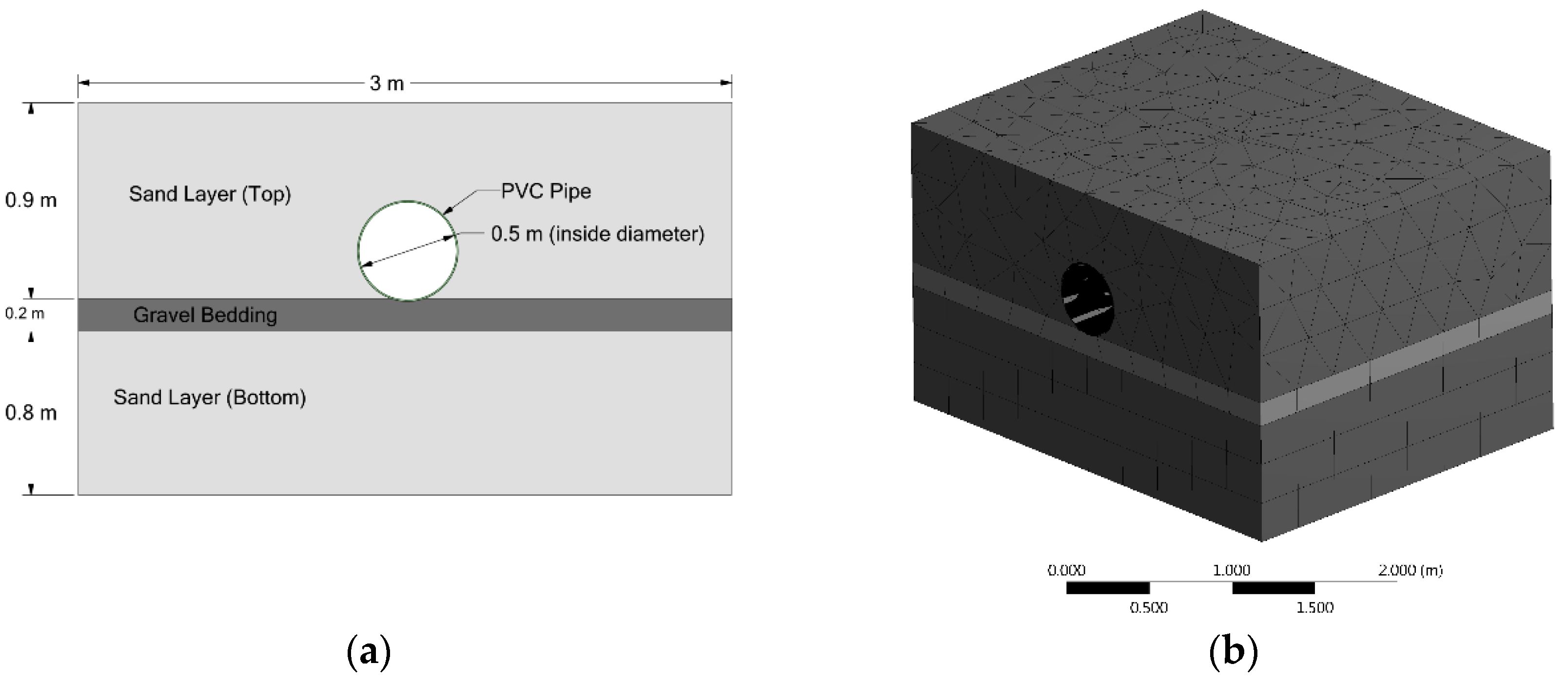
The laboratory experiment was taken from a previous study by Edgar et al. [
22]. In their study, a container box (referred to as soil box) with a circular hole drilled on each of two opposite side faces, as shown in
Figure 1, was used to measure pipe behavior under external loading. Pipes of different materials were inserted through the two holes in different experiments. The soil box was filled with compacted layers of granular materials. The sides of the box were reinforced with I-beams to prevent bulging of the box due to the weight of the soil. After inserting the pipe and filling the box with soil layers, a static load was applied at the center of the top surface above the pipe. Strain gauges and linear variable differential transformers (LVDTs) were instrumented on the pipe to measure its strain and deformation, respectively. In the experiment, a 107 kN static load was applied gradually, and the maximum vertical displacement of the pipe crown was measured at 2.8 mm.
In this study, an FE model was constructed in the FE software ANSYS Workbench 19.1, as shown in
Figure 1b, to represent the experimental setup and mimic the behavior of the different components of the soil box when an unjointed PVC pipe was inserted. The geometric and material information of the test setup was extracted from the reference paper, with reasonable assumptions. For example, while the depth of cover of the PVC pipe was given in the reference, the thickness of the different soil layers was only partially reported. It was mentioned that clear sand was used to create a 0.4 m depth of cover in the top layer. The thickness of the top soil layer, therefore, can be reasonably derived as 0.9 m, which is the depth of cover plus the diameter of the pipe (0.5 m). The thickness of the gravel layer (0.2 m) was given in the reference. The thickness of the bottom sand layer was assumed to be 0.8 m, based on the provided diagram, where the bottom layer is slightly thinner than the top layer [
22]. While the soil parameters were given, the properties of the pipe material were not reported, except for its material type (polyvinyl chloride, PVC). Therefore, typical parameter values of PVC materials were used in the model. All model components (granular layers and the pipe) were treated as solid bodies with linear elasticity, as can be defined by modulus of elasticity and Poisson’s ratio. This choice was made based on the common practice in pavement engineering of modeling the pavement structure as layers of elastic bodies, which results in a good agreement between predicted and measured pavement structural responses to vehicle loads [
27,
28,
29]. The boundary condition of the soil box was defined by a fixed support (all six degrees of freedom were restricted, since the faces of the box were braced using I-beams) at all surfaces, except the top. In the laboratory experiment, both ends of the pipe were extended beyond the soil box boundary. It was considered that the actual representation of this condition in the FE model could be simulated by restricting the pipe ends (truncated at the boundary of the box) against all six degrees of freedom, to represent continuity of the pipe. Another important consideration was the definition of the behavior of the interface between the different soil layers and the pipe. The prevalent practice in the literature is to define a bonded connection for the interface between soil layers and the pipe. In this study, the interface was treated as partially bonded with a friction coefficient. In the later model calibration, it was found that a friction coefficient of 0.1 was sufficient for a good agreement between predicted and observed pipe responses. The shape and structure of the FE mesh were defined as the program defaults. The minimum mesh size was 152 mm for the pipe and 304 mm for the granular layers. The static load applied at the center of the top surface was modeled as a vertical point load distributed over a rectangular tire foot print [
29].
Table 2 lists the material properties and dimensions of the different components assumed in the FE model to simulate the soil box experiment.
The rate at which the load was applied in the soil box experiment is not mentioned in [
22]. In the FE model, we applied the 107 kN load in 60 s at a uniform rate in 20 steps. The model predicted the maximum vertical deflection of the pipe crown at each step for the corresponding loading magnitude level. A plot between the load magnitude and vertical deflection of the pipe crown from the static test on the unjointed PVC pipe showed an approximately linear relationship [
22]. As enough data were not available to recreate the plot, we constructed a linear relationship using the displacements reported at 0 and 107 kN, as shown in
Figure 2. The maximum pipe crown displacements predicted by the FE model at different loading levels are also plotted in the same graph. As can be seen, the pipe response predicted by the FE model closely matches the pipe response recorded in the laboratory experiment. The pipe deflection under the 107 kN load was recorded at 2.87 mm in the soil box experiment and predicted at 2.79 mm in the FE model.
4. Experimental FE Model of Buried Pipe under Heavy Vehicle Loading
The validation model helped to determine the appropriate parameter values and to define proper component behaviors of the experimental model for a buried structure subjected to external loads. Our experimental model is a cuboidal section of a layered pavement structure with a pipe buried below the surface, with dimensions of 30.5 m length, 6.5 m depth, and 6.1 m width. It was deemed that such dimensions are sufficient to accommodate pipe responses due to vehicle point loads, while fitting within the software computational capacity. The pipe length equals the length or the width of the model, depending on the orientation of the pipe relative to the vehicle chassis. The typical layered structure of the buried pipe system consists of an asphalt concrete (AC) layer at the top, a base layer, and a subgrade soil layer. In the model, the pipe is placed at a depth equal to the appropriate depth of cover. A schematic of the experimental model with typical dimensions is shown in
Figure 3.
For the analysis of the primary experimental model, typical properties of pavement and pipe materials, as shown in
Table 3, were used. The selected parameter values of pavement and pipe materials were close to the minimum values in the range of typical material property values of the corresponding parameter. Parameter values were selected in this manner, to ensure that the experimental model represented the most vulnerable and critical condition, where relatively weak materials are used. This was coupled with a maximum loading scenario. Like the validation model, all the FE models in this study treated various pavement layers as solid bodies with linear elasticity.
4.1. Loading Scenario for the Experimental Model
Among all conventional vehicles operating on a road network, trucks have considerably higher impacts on the structure beneath than lighter vehicles. For this reason, almost all studies investigating the impact of external vehicle loads on buried pipes have considered heavy truck loads. The effect of vehicle loads is considered in different ways in the design of pavements and bridges. Similar to the standard live load considered in bridge design, an AASHTO H-20 or HS-20 truck load is usually considered in pipe design [
9,
30]. Consequently, a number of studies have also considered similar loading in understanding the effect of external loads on buried pipes. However, trucks heavier than HS-20 are allowed on the road network in the USA, according to the FHWA regulations. The maximum federal allowable gross weight of a heavy truck is 356 kN (80 kips). Eventually, the buried structures will be subjected to these external heavy loads, even though their percentage in the traffic stream is low. Since the objective of this study is to understand the impact of heavy vehicle movement on buried pipes, especially when critical conditions arise, the maximum allowable limit of gross truck weight was selected as the total truck load, without being unrealistic in the assumption of critically heavy loads.
Figure 4 shows the heavy truck considered in this study, which is representative of the loading condition of the six-axle tractor semi-trailers in the actual truck fleet.
4.2. Experimental Analysis Using the FE Model
4.2.1. Phase I Analysis of Pipe Response under Normal Operating Conditions
Scenario 1: Pipe Behavior against Variation of Vehicle Loads
The first scenario of FE analysis investigated how the pipe response varied with the application of various loads from heaviest trucks in the truck fleet. In selecting the loads, we considered the current federal regulation for allowable maximum weight of heavy vehicles in the USA. Our study truck consisted of six-axles in three axle groups. The axle in the front consists of two wheels, and is referred to as the steering axle. Towards the middle of the truck, two axles are grouped into a tandem axle, containing eight wheels. Towards the end of the truck, three axles are grouped into a tridem axle containing 12 wheels. The federal maximum load limits for gross vehicle weight (356 kN) distributed in three axle groups, which are 53, 133, and 178 kN (10, 30, and 40 kips), respectively, were followed in this study. In the first stage, the application of the truck load configuration shown in
Figure 4 on the buried pipe was modeled, with the center line of the truck chassis aligned with the longitudinal axis of the pipe, which was discovered to be the most critical loading position. Another point of interest here is the clarification of the combined effects on pipes from more than one axle. Previous studies on pipe behavior under vehicle loads did not provide any clarification about whether the effect of a single axle placed at the critical position above the pipe is significantly different from the combined effects of more than one axle. We first applied the loads from different types of axles individually, then gradually increased the number of axles from our study truck and analyzed the pipe behavior. Finally, the combined effect of two trucks with a reasonable spacing of 6.1 m (20 ft) on the buried pipe was evaluated. In a second stage, the pipe response to truck loads placed perpendicular to the pipe (i.e., the truck crossing a pipe) was analyzed with the middle axle of the heaviest axle group placed above the pipe, as this was found to be the most critical loading position. Changes in the pipe response, in terms of maximum vertical deflection, with various axle combinations and orientations are shown in
Figure 5 for a ductile iron pipe.
The following observations can be made from
Figure 5. First, the response in the buried pipe was mainly caused by a single, tandem, or tridem axle. For example, when all the axles of a single truck are in action, the maximum deflection is still governed by the heaviest axle (tridem axle in this case), and the magnitude remains almost the same when only a tridem axle load is applied. This means that the axle groups are placed in such a way that their impacts on the pipe are independent from each other. This also applies to axles from multiple trucks. Therefore, to observe the behavior of a pipe in critical conditions, we do not need to consider all the axle loads of the truck in our model. A relatively smaller geometric model may be adopted with the heaviest axle load, to assess pipe responses for a shorter computation time in the FE analysis. Second, the impact on the pipe is significantly greater when the pipe is placed across the roadway (labelled as ‘transverse orientation’ in
Figure 5).
Based on the above observations, all subsequent experimental analyses were conducted on a small-scale model with finer meshes. The smaller model had the same layered structure as shown in
Figure 3, but with reduced horizontal dimensions, 6.1 m (20 ft) in width and 6.1 m (20 ft) in length. Only the tridem axle load layout was applied, since it caused the highest vertical deflection among all the loading conditions considered in Scenario 1. Moreover, in all the subsequent scenarios, the axle load was positioned perpendicular to the pipe, with the middle axle of the tridem axle group aligned with the longitudinal axis of the pipe.
Scenario 2: Pipe Behavior against Variation of Pipe Dimensions
In this section, the pipe behavior under a fixed vehicle load against varying pipe dimensions is analyzed. The state-of-practice standard pipe dimensions for different pipe materials were considered in the analysis. For example, the American Water Works Association (AWWA) specifies a range of standard pipe dimensions (diameter and thickness) specific to the constituting pipe materials. The thickness of equal diameter pipes may vary according to their capacity to withstand certain levels of working water pressure. Based on this property, pipes of identical diameters are categorized into different pressure classes. For example, ductile iron pipes of 1016 mm (40 inches) diameter come with varying thickness, according to their pressure class. When we selected a standard pipe diameter for analysis, the thinnest pipe (lowest pressure class) of that diameter was selected among the available pressure classes. We considered pipes made of the following materials: Ductile iron (DI), polyvinyl chloride (PVC), and high-density polyethylene (HDPE), whose typical properties (isotropic elasticity) are provided in
Table 3.
Table 4 lists the standard pipe diameter and corresponding minimum wall thickness recommended for the lowest available pressure class. The impact of cover depth on pipe behavior was also analyzed. In this step, we considered two different cover depths for each selected pipe.
Pipe responses were determined using the smaller structural model, as determined in Scenario 1.
Figure 6 presents the analysis results, in terms of maximum pipe deflection under fixed vehicle loading, but with various pipe outer diameters and cover depths. The results include a range of pipe diameters, from the smallest to the largest, based on the standard dimensions specified by the AWWA for the three pipe materials (DI, PVC, and HDPE). Some notable features of the pipe response against varying pipe dimensions can be observed in
Figure 6. For HDPE and PVC pipes, their maximum deflection increases with the increase of their outer diameter. For DI pipes, the trend is the opposite. Regarding the impact of cover depth, the general trend is that for almost all pipe materials across the entire dimension spectrum, pipes buried at 0.91 m (3 ft) depth experience smaller vertical deflection than pipes buried at 0.61 m (2 ft) depth. However, there are a few observations that contradict this general observation. The largest vertical deflection was recorded in the HDPE pipe with an outer diameter of 1405 mm, a specified wall thickness of nearly 44 mm, and buried at 0.61 m (2 ft) depth. Notice that, if we compare the allowable maximum deflection (70 mm) for a pipe of this dimension with the observed deflection (0.8 mm), the observed deflection can be considered negligible. However, if we compare the performance of the pipe with the maximum allowable deflection, in terms of percentage of pipe diameter, the larger pipes perform better. For example, the maximum deflection (in percentage of diameter) occurred in the HDPE pipe of 80 mm outer diameter, whereas in larger pipes, this value was close to 0%.
4.2.2. Phase 2 Analysis of Pipe Response under Potential Critical Scenarios
The central objective of this study was to understand if buried water pipes are physically affected by heavy vehicle loads. This will help in understanding the broad interdependency between water and road infrastructures, for ensuring their resiliency and sustainability in future environments. Our analysis so far indicates that even the heaviest load from currently operational trucks has a negligible effect on the serviceability and the structural integrity of buried pipes, based on the pipe responses recorded in the previous analyses. In this section, we analyze the truck impact when the pipes are in a vulnerable condition. Two common vulnerable scenarios, corroded pipes and sinkhole or void formation underneath the pipes, are considered in the analysis. The highest magnitude truck loading considered in the previous analyses will also be applied in these scenarios. In all subsequent experimental models, a cover depth of 0.61 m (2 ft) is used, due to the consistency in model outputs observed in the previous experimental model, as well as being more representative of actual cover depth in the current state of practice.
Corrosion in DI Pipes
According to [
31], the predominant cause of failure in buried utility pipes is corrosion. Moreover, a large portion of buried pipes are made of materials that are susceptible to corrosion, such as cast iron and ductile iron [
32]. The effect of corrosion in elastic metal pipes includes reduction in yields and toughness strengths, reduction in pipe thickness due to erosion of rusted bits of metals from the pipe, and formation of small holes in pipes in a similar fashion [
31]. An important step in simulating corroded pipes is to figure out a way to represent these corrosion defects in pipes in the model. Researchers previously used holes (corrosion pit) of different shapes (e.g., rectangular, elliptical) in the middle of the inner or outer pipe walls to represent corrosion affected regions in metal pipes [
33,
34,
35]. Lee and Kim concluded that the geometry of these corrosion pits significantly affects the structural behavior of the corroded pipe [
34]. For the sake of simplicity in the analysis, and due to the limited scope, we used a rectangular (with curvilinear sides on the curved pipe surface) corrosion pit. The dimension of the corrosion pit was (r × r/2), where r is the inner radius of the pipe. This dimension was chosen to represent the reduction in pipe materials due to corrosion and subsequent erosion of loose materials in a manner that is proportional to the size of the pipe.
Since larger pipes have a larger surface area exposed to the surrounding environment, it was assumed that the material reduction in the pipe cross section is higher in larger pipes, leading to greater pits. However, the depth of the corrosion pit varied according to the corrosion severity in the pipe. We modeled three levels of corrosion in ductile iron pipes: minimum, intermediate, and severe, which correspond to 25%, 50%, and 75% reductions in pipe thickness, respectively. Based on the results observed in an initial model trial run, the most critical placement of the corrosion pit was found to be on the pipe surface, directly below the mid axis of the two sides of the axle. We simulated this scenario by creating a single pit at that point. Moreover, since metal pipes are generally more susceptible to corrosion, we simulated this phase only for ductile iron pipes.
5. Discussion and Conclusions
The main objective of this study was to uncover if heavy vehicles would affect the underlying water pipes of state-of-practice designs, so as to provide a better understanding of the interdependency between water and road infrastructure systems. In our analysis, hydraulic loading on the pipe was not considered, since the focus was on understanding the effect of heavy vehicle loads. The pipe response presented in this paper is mainly the maximum pipe deflection. The stress response in the pipe was also analyzed, but not reported, mainly because the maximum tensile stress revealed in the analysis was very low, which would not lead to fatigue damage in the pipe, even after a very large number of load repetitions.
This study found that the critical response in a pipe to vehicle loads was dominated by one axle group from a vehicle, so there was no need to consider the entire truck or fleet of trucks in modeling. It was also found that a pipe experiences the largest effect when the pipe is laid out across the direction of vehicle movement. In case of flexible pipe materials (i.e., PVC and HDPE), the magnitude of pipe deflection increases with the increase of pipe diameter, whereas for ductile iron pipes the result was the opposite. However, if we consider the percent deflection with respect to the pipe diameter, larger pipes made up of all three materials were more stable compared to smaller pipes.
The overall finding is that the critical pipe response in terms of vertical deflection is significantly lower than the allowable value, even under extremely vulnerable conditions, such as serious pipe corrosion or the existence of a sinkhole. While existing studies on the effect of external loads on buried infrastructures covered some scenarios, this study fills in the gaps by providing a direct conclusion, that even the heaviest truck within current federal regulations does not significantly affect buried pipes. Hence, water pipes affected by heavy vehicles need not be considered as a structural interdependency case between these two infrastructures. While other examples of potential interdependency cases need to be considered (e.g., operational and social interdependencies), a structural interdependency does not propagate from road to water pipes under vehicle loads.
With the above conclusions drawn, it should be noted that there are a few limitations to this study. Although we considered a number of pipe materials, dimensions, loading scenarios, and multiple critical situations, the list was not exhaustive. Variation in the layer structure above the pipe was not considered, to avoid complexity in the analysis. Other pipe materials, such as cast iron, steel, and concrete were not considered, because they are much less commonly used in practice for water pipes. The finite element model constructed in this study, however, may be easily adapted with new components and parameters, for analyzing new field scenarios.
Author Contributions
Conceptualization, S.U., Q.L. and H.N.; methodology, S.U.; software, S.U. and H.N.; validation, S.U.; formal analysis, S.U.; investigation, S.U. and Q.L.; resources, Q.L.; data curation, S.U.; writing—original draft preparation, S.U.; writing—review and editing, S.U. and Q.L.; visualization, S.U.; supervision, Q.L.; project administration, Q.L.; funding acquisition, Q.L. All authors have read and agreed to the published version of the manuscript.
Funding
This research was conducted with support from the US National Science Foundation’s Critical Resilient Interdependent Infrastructure Systems and Processes (NSF CRISP) program, Grant No. 1638301. Any opinions, findings, and conclusions or recommendations expressed in this material are those of the authors and do not necessarily reflect the views of the National Science Foundation.
Data Availability Statement
Some or all data, models, or code that support the findings of this study are available from the corresponding author upon reasonable request.
Conflicts of Interest
The authors declare no conflict of interest.
References
- Samimpey, R.; Saghatforoush, E. A Systematic Review of Prerequisites for Constructability Implementation in Infrastructure Projects. Civ. Eng. J. 2020, 6, 576–590. [Google Scholar] [CrossRef] [Green Version]
- Majeed, A.K.; Erzaij, K.R. Cost & Time Interaction Behavior on Construction Materials Procurement and Execution Processes in Infrastructure Projects. Civ. Eng. J. 2020, 6, 531–539. [Google Scholar] [CrossRef] [Green Version]
- Di Bona, G.; Forcina, A.; Falcone, D.; Silvestri, L. Critical Risks Method (CRM): A New Safety Allocation Approach for a Critical Infrastructure. Sustainability 2020, 12, 4949. [Google Scholar] [CrossRef]
- Dudenhoeffer, D.; Permann, M.; Manic, M. CIMS: A Framework for Infrastructure Interdependency Modeling and Analysis. In Proceedings of the 38th Conference on Winter Simulation; Winter Simulation Conference, Monterey, CA, USA, 3–6 December 2006; pp. 478–485. [Google Scholar]
- Avitabile, R. Water Main Break Forces Road Closure in El Cajon. Available online: http://www.nbcsandiego.com/news/local/Water-Main-Break-Forces-Road-Closure-in-Unincorporated-El-Cajon-506475961.html (accessed on 20 March 2019).
- Thompson, T. Water Pipe Break Leads to Road Closures Saturday. Available online: http://wgxa.tv/news/local/water-pipe-break-leads-to-road-closures-saturday (accessed on 20 March 2019).
- Ouyang, M. Review on Modeling and Simulation of Interdependent Critical Infrastructure Systems. Reliab. Eng. Syst. Saf. 2014, 121, 43–60. [Google Scholar] [CrossRef]
- Rinaldi, S.M.; Peerenboom, J.P.; Kelly, T.K. Identifying, Understanding, and Analyzing Critical Infrastructure Interdependencies. IEEE Control. Syst. Mag. 2001, 21, 11–25. [Google Scholar] [CrossRef]
- AWWA. C150/A21.50-96: American National Standard for Thickness Design of Ductile-Iron Pipe. Available online: https://www.awwa.org/Store/{ProductName}/ProductDetail/{ProductId}?productId=18789 (accessed on 7 June 2020).
- Compilation of Existing State Truck Size and Weight Limit Laws—FHWA Freight Management and Operations. Available online: https://ops.fhwa.dot.gov/freight/policy/rpt_congress/truck_sw_laws/index.htm (accessed on 23 July 2021).
- Alzabeebee, S.; Chapman, D.N.; Faramarzi, A. A Comparative Study of the Response of Buried Pipes under Static and Moving Loads. Transp. Geotech. 2018, 15, 39–46. [Google Scholar] [CrossRef]
- Yeau Kyong, Y.; Halil, S.; Fox Patrick, J. Load Performance of In Situ Corrugated Steel Highway Culverts. J. Perform. Constr. Facil. 2009, 23, 32–39. [Google Scholar] [CrossRef]
- Beben, D. Dynamic Amplification Factors of Corrugated Steel Plate Culverts. Eng. Struct. 2013, 46, 193–204. [Google Scholar] [CrossRef]
- Timothy, S.; Halil, S.; Moore Ian, D. Joint Response of Existing Pipe Culverts under Surface Live Loads. J. Perform. Constr. Facil. 2015, 29, 04014037. [Google Scholar] [CrossRef]
- Raju, A.; Jie, H.; Brennan James, J.; Parsons Robert, L. Khatri Deep Kumar Structural Response of a Low-Fill Box Culvert under Static and Traffic Loading. J. Perform. Constr. Facil. 2016, 30, 04014184. [Google Scholar] [CrossRef]
- Katona, M.G. Minimum Cover Heights for Corrugated Plastic Pipe Under Vehicle Loading. Transp. Res. Rec. 1990, 1288, 127–135. [Google Scholar]
- Madasamy, A.; Omar, C. Limpeteeprakarn Terdkiat Full-Scale Field Tests on Flexible Pipes under Live Load Application. J. Perform. Constr. Facil. 2006, 20, 21–27. [Google Scholar] [CrossRef]
- Kang, J.; Stuart, S.J.; Davidson, J.S. Analytical Study of Minimum Cover Required for Thermoplastic Pipes Used in Highway Construction. Struct. Infrastruct. Eng. 2014, 10, 316–327. [Google Scholar] [CrossRef]
- Omar, C.; Madasamy, A.; Ahmed, G. Field Test Performance of Buried Flexible Pipes under Live Truck Loads. J. Perform. Constr. Facil. 2015, 29, 04014124. [Google Scholar] [CrossRef]
- Omar, C.; Madasamy, A.; Ahmed, G. Numerical Finite-Element Investigation of the Parameters Influencing the Behavior of Flexible Pipes for Culverts and Storm Sewers under Truck Load. J. Pipeline Syst. Eng. Pract. 2015, 6, 04014015. [Google Scholar] [CrossRef]
- CTS&W Limits Study: Volume 1 Technical Reports Summary—Chapter 2: Scope and General Methodology. Available online: https://ops.fhwa.dot.gov/freight/sw/map21tswstudy/technical_rpts/vol1technicalsummary/02scope_methd.htm#t4 (accessed on 31 July 2021).
- Edgar, K.; Jeongho, O.; Fernando Emmanuel, G. Impact of Repeat Overweight Truck Traffic on Buried Utility Facilities. J. Perform. Constr. Facil. 2014, 28, 04014004. [Google Scholar] [CrossRef]
- Association, A.W.W. Buried No Longer: Confronting America’s Water Infrastructure Challenge; American Water Works Association: Denver, CO, USA, 2012. [Google Scholar]
- Folkman, S. Water Main Break Rates in the USA and Canada: A Comprehensive Study; Utah State University Buried Structures Laboratory: Logan, UT, USA, 2018. [Google Scholar]
- Jones, H. Water Main Break Causes Sinkhole in Southcrest. Available online: https://www.sandiegouniontribune.com/news/public-safety/story/2020-01-21/water-main-break-causes-sink-hole-in-southcrest (accessed on 4 June 2020).
- Parker, J. Water Main Break in West El Paso Causes Sinkhole; Water Flows Downhill for Miles. Available online: https://kvia.com/news/el-paso/2020/02/06/water-main-break-in-west-el-paso-causes-sinkhole-water-flows-downhill-for-miles/ (accessed on 12 October 2021).
- Maina, J.W.; Ozawa, Y.; Matsui, K. Linear Elastic Analysis of Pavement Structure under Non-Circular Loading. Road Mater. Pavement Des. 2012, 13, 403–421. [Google Scholar] [CrossRef]
- Akbulut, H.; Aslantas, K. Finite Element Analysis of Stress Distribution on Bituminous Pavement and Failure Mechanism. Mater. Des. 2005, 26, 383–387. [Google Scholar] [CrossRef]
- Hadi, M.N.S.; Bodhinayake, B.C. Non-Linear Finite Element Analysis of Flexible Pavements. Adv. Eng. Softw. 2003, 34, 657–662. [Google Scholar] [CrossRef]
- Association, A.W.W. PVC Pipe—Design and Installation; American Water Works Association: Denver, CO, USA, 2002; Volume 23, ISBN 1-58321-171-3. [Google Scholar]
- Hou, Y.; Lei, D.; Li, S.; Yang, W.; Li, C.-Q. Experimental Investigation on Corrosion Effect on Mechanical Properties of Buried Metal Pipes. Int. J. Corros. 2016, 2016, 1–13. [Google Scholar] [CrossRef] [Green Version]
- Li, Y.; Hasegawa, K.; Onizawa, K.; Cofie, N.G. Prediction of Collapse Stress for Pipes With Arbitrary Multiple Circumferential Surface Flaws. J. Press. Vessel. Technol. 2010, 132, 061204. [Google Scholar] [CrossRef]
- Belachew, C.T.; Ismail, M.C.; Karuppanan, S. Burst Strength Analysis of Corroded Pipelines by Finite Element Method. J. Appl. Sci. 2011, 11, 1845–1850. [Google Scholar] [CrossRef]
- Lee, O.-S.; Kim, H.-J. Effect of External Corrosion in Pipeline on Failure Prediction. Int. J. Precis. Eng. Manuf. 2000, 1, 48–54. [Google Scholar]
- Szary, T. The Finite Element Method Analysis for Assessing the Remaining Strength of Corroded Oil Field Casing and Tubing. Ph.D. Thesis, Technischen Universität Bergakademie Freiberg, Freiberg, Germany, 2006. [Google Scholar]
- Ali, H.; Choi, J. A Review of Underground Pipeline Leakage and Sinkhole Monitoring Methods Based on Wireless Sensor Networking. Sustainability 2019, 11, 4007. [Google Scholar] [CrossRef] [Green Version]
- Ali, H.; Choi, J. Risk Prediction of Sinkhole Occurrence for Different Subsurface Soil Profiles Due to Leakage from Underground Sewer and Water Pipelines. Sustainability 2020, 12, 310. [Google Scholar] [CrossRef] [Green Version]
- Indiketiya, S.; Jegatheesan, P.; Rajeev, P.; Kuwano, R. The Influence of Pipe Embedment Material on Sinkhole Formation Due to Erosion around Defective Sewers. Transp. Geotech. 2019, 19, 110–125. [Google Scholar] [CrossRef]
| Publisher’s Note: MDPI stays neutral with regard to jurisdictional claims in published maps and institutional affiliations. |
© 2021 by the authors. Licensee MDPI, Basel, Switzerland. This article is an open access article distributed under the terms and conditions of the Creative Commons Attribution (CC BY) license (https://creativecommons.org/licenses/by/4.0/).


