Article

Performance Assessment and Working Fluid Selection for Novel Integrated Vapor Compression Cycle and Organic Rankine Cycle for Ultra Low Grade Waste Heat Recovery

1
School of Professional Education & Executive Development, The Hong Kong Polytechnic University, Kowloon, Hong Kong
2
Institute of Energy & Environmental Engineering, University of Punjab, Lahore 54590, Pakistan
3
Department of Mechanical Engineering, University of Engineering & Technology, Lahore 54890, Pakistan
4
Wolfson School of Mechanical, Electrical and Manufacturing Engineering, Loughborough University, Loughborough LE11 3TU, UK
5
School of Mechanical Engineering, Wuxi 214024, China
6
School of Engineering and Applied Science, Mechanical Engineering and Design, Aston University, Birmingham B4 7ET, UK
7
Department of Mechanical and Construction Engineering, Northumbria University, Newcastle upon Tyne NE7 7YT, UK
8
Ability R & D Energy Research Centre, School of Energy and Environment, City University of Hong Kong, Kowloon, Hong Kong
*
Authors to whom correspondence should be addressed.
Sustainability 2021, 13(21), 11592; https://doi.org/10.3390/su132111592
Submission received: 24 September 2021 / Revised: 18 October 2021 / Accepted: 18 October 2021 / Published: 20 October 2021
(This article belongs to the Special Issue Hybrid Energy System)

Abstract

:
This paper presents the performance assessment and working fluid selection for a novel integrated vapor compression cycle-organic Rankine cycle system (i-VCC-ORC), which recovers ultra-low-temperature waste heat rejected (50 °C) by the condenser of a vapor compression cycle (VCC). The analyses are carried out for a vapor compression cycle of a refrigeration capacity (heat input) of 35kW along with the component sizing of the organic Rankine cycle (ORC). The effects of the operational parameters on integrated system performance were investigated. The integrated system performance is estimated in terms of net COP, cycle thermal efficiency and exergy efficiency by completely utilizing and recovering the heat rejected by the condenser of the VCC system. R600a-R141b with COPnet (3.54) and ORC thermal efficiency (3.05%) is found to be the most suitable VCC-ORC working fluid pair. The integration of the vapor compression refrigeration cycle with the organic Rankine cycle increases the COP of the system by 12.5% as compared to the standalone COP of the vapor compression system. Moreover, the sensitivity analysis results show that there exists an optimum operating condition that maximizes the thermal performance of the integrated system.

1. Introduction

The utilization of low-temperature waste heat (solar, geothermal, waste heat and biomass, etc.) can significantly contribute to reducing conventional and non-renewable ways of power generation, thereby relieving the associated environmental aspects [1]. The efficient heat recovery from waste or a low-temperature heat source can play a major role in mitigating the greenhouse gas emissions and improving energy efficiency. Many different approaches and thermodynamic cycles were adopted for the recovery of the waste heat. The Organic Rankine cycle (ORC) is considered to be a viable technology for the efficient recovery of waste heat [2]. The working of the ORC is similar to the conventional steam of the Rankine cycle except it uses the organic compounds as working fluid instead of steam. The boiling point of an organic compound is less than water due to which it can harness a greater amount of energy from various low-temperature heat sources such as solar, geothermal reservoirs and waste heat from various industrial processes [3,4,5] which cannot be recovered by conventional energy conversion technologies. In tropical regions, 56% of the energy in the building is used for air conditioning [6]. According to the Hong Kong report in 2017, the total amount of energy consumed by the end user was 287,986 TJ. Out of this, 48,466 TJ (17% of total energy) of energy accounts for the air conditioning and 8717 TJ (3% of total energy) of energy was consumed by refrigeration [7]. The most widely used air-conditioning cycle is the vapor compression refrigeration cycle (VCC). The condenser of the VCC rejects a considerable amount of heat into the environment at a low temperature. This low-temperature waste heat can be effectively recovered by the ORC for electricity production. This technology has large market potential and can significantly reduce the electrical consumption of residential and industrial levels. Few research studies were conducted in the past where the ORC system was integrated with the vapor compression cycle, but heat input to the ORC system was from an external source. Some configurations utilized the expander work to drive the compressor of the VCC system.
Prigmore and Barber [8] developed the first prototype of the ORC and VCC integrated system. An ORC with R113 as the working fluid was connected to the R12 VCC and generator. Their major target was to provide three ton of residential cooling and one kWe of electricity by receiving heat for the ORC from solar energy. The maximum system COP of 0.71 was achieved with a warm water temperature of 102 °C. Muhammad Tauseef Nasir and K.C. Kim [9,10,11] developed an ORC-powered VCC system and performed multi-objective optimization for air conditioning applications They analyzed the thermal performance and optimized the system using TOPSIS. Using multiple combinations of working fluid in an integrated system, hot water at 100 °C and 1.5 bar was used as a heat source. The R134a ORC-Isobutane VCC was the best combination with a maximum net COP of 0.281. Muhammad Asim et al. [12] performed a thermodynamic and thermo-economic analysis on an integrated vapor compression cycle and ORC to find out the best fluid pair in the integrated cycle. The R600a VCC-R123 ORC was found to be the best fluid pair with a net COP, thermal efficiency and exergy efficiency of 3.54, 3.05% and 39.30%. J. Bao et al. [13] performed the comparative study on a combined ORC and VCC cycle using single and dual fluid and geothermal water at 140 °C as the heat source. At this heat source temperature, the single fluid and dual fluid ORC-VCC system has cooling capacities of 1919 kW and 2133 kW with optimum working fluids of the R1234yf (single fluid) and R1234yf-R152a (dual fluid) ORC-VCC system. S. Aphornratana and T. Sriveerakul [14] described the theoretical analysis of the VCC and ORC coupled together with an expander-compressor unit. R22 and R134a were used as system working fluids. The integrated system shared the same working fluid and same condenser. With the generator and condenser temperature of 60–90 °C and 30–50 °C, respectively, the system COP values varying between 0.1 and 0.6 were found. F. Moles et al. [1] evaluated the combined ORC-VCC system activated by low-temperature heat sources and low global warming potential working fluids. The computed thermal and electrical COPs of the combined system were found to be varied between 0.30–1.10 and 15–110. HFO-1336mzz(Z) and HFO-1234ze(E) were found to be the optimum fluids for the ORC-VCC integrated system. Kim KH and Perez-Blanco H [15] performed a thermodynamic analysis on a combined ORC-VCC for power and refrigeration using the same working fluids. Isobutane was used for the sensitivity analysis because of its high thermal efficiency. The results showed that the system has the potential to use low-grade thermal energy effectively with a temperature higher than 90 °C. Furthermore, the minimum cooling temperature of 5 °C can be achieved by both systems. Toujani N., et al. [16] studied the impact of various operating parameters on various ORC-VCC combinations for cogeneration. Various heat sources (biomass and solar) at low temperatures ranging from 80 to 160 °C were modeled to analyze the performance of a new system combining ORC-VCC systems for refrigeration and electricity production. At heat source temperatures less than 150 °C, the maximum COP of VCC cycles is 14.33, and the system COP is 0.7 with a system network and cooling capacity of 100 kW and 1300 kW, respectively. Saleh [17] performed the parametric analysis on an integrated ORC-VCC system. The system is sharing a common condenser, and the expander power is sufficient to drive the compressor and pump. A low-temperature heat source around 100 °C was used to power the system using 10 different working fluids. R600 is found to be the best working fluid with a COP up to 0.718 at a condenser temperature of 30 °C having the lowest total mass flow rate.
D.K. Kim et al. [18] performed the parametric evaluation on the ORC using a low-grade waste heat below 80 °C using R245fa as the working fluid. He found out that the system is able to generate 411.3W with 3.6% efficiency at a heat source temperature of 80 °C. Javanshir et al. [19] performed the parametric study on an integrated vapor compression and the organic Rankine cycle using geothermal water as the low-temperature heat source. R143a was found to be the best working fluid with thermal and exergy efficiencies of 27.2% and 57.9%, respectively. Zhao et al. [20] analyzed the system parameters with different working fluids using low-grade waste heat at 85 °C and concluded that R123 was an effective working fluid in terms of high thermal efficiency and turbine power output. Khatoon et al. [21] performed a thermodynamic analysis of an ORC-powered VCC cycle for different working fluids using a low-grade heat source. A R123-based refrigeration cycle and propane-based ORC system have the highest thermodynamic performance with a cycle efficiency of 16.48% and COP value of 2.85 at a 40 °C condenser temperature. Lakew et al. [22] conducted a comparison on the performance of ORC systems using different working fluids and found that R227ea was suitable for heat sources at 80–160 °C. In these studies, the energetic and exergetic analysis and related results were considered as effective approaches and key parametric indicators [17,18,19]. Kumar et al. [23] assessed the combined ORC-VCC cycle thermodynamically using low-grade thermal energy sources and low GWP and ODP refrigerants. R152a and R290 were found to be the potential candidates for the integrated system. Moreover, 152a is a high-performing working fluid having a COP lower than R22 by 3%, whereas R290 has a maximum cooling capacity having a COP lower than that of R22 by 8.5%.
Although the VCC system rejects a considerable amount of energy at a low temperature, the efficient recovery of this heat for electricity production, especially with this integrated configuration, has not been discussed in the open literature. If this heat is effectively recovered, it can improve the COP of the air-conditioning system. With successful implementation, it is expected to contribute in reducing the total amount of waste heat, enhancing the commercial appeal of waste heat recovery in the air-conditioning system, reducing the greenhouse gas emission and realizing sustainable development.
In this paper, a novel integrated vapor compression cycle and organic Rankine cycle (i-VCC-ORC) system for ultra-low-grade waste heat recovery is presented. The configuration is unique in a sense that the ORC is being driven by the waste heat rejected by the condenser of the vapor compression refrigeration (VCC) cycle. The recovered waste heat is being utilized by the ORC for electricity production. The present work focuses on the design, working fluid selection and performance assessment of the i-VCC-ORC system. The system performance is measured in terms of net COP, cycle thermal efficiency and exergy efficiency.

2. Materials and Methods

In this section, an integrated vapor compression cycle (VCC) and organic Rankine cycle system (ORC) for low-grade waste heat recovery is presented. Figure 1 shows the proposed configuration of the integrated VCC-ORC system. In this approach, the waste heat rejected by the condenser of the VCC (state points 2–3) system is fully recovered by a shared heat exchanger to drive the ORC system. The VCC system primarily consists of a compressor, a shared heat exchanger (SHX), an expansion valve and an evaporator, while in the ORC, the expander, condenser, pump and evaporator (shared heat exchanger) are the main components. The SHX between the VCC and ORC works as the condenser in the VCC as well as the evaporator in the ORC. In the VCC, the low-pressure vapor (state 1) is compressed and exits as high-pressure superheated vapor (state 2). Through condensation, the high-pressure superheated vapor is liquefied (state 3) by the ORC working fluid. The low-pressure saturated refrigerant liquid and vapor leave the expansion valve (state 4) and enter the evaporator. The evaporation process cools the return chilled water (state 9) to the chilled water supply (state 10). In the ORC, the low-pressure liquid (state 5) is pumped to high pressure (state 6) and delivered to the evaporator. The high-pressure vapor (state 7) flows out of the evaporator after gaining heat and then enters the turbine. The expansion process in the turbine produces mechanical power that drives the generator to produce electricity. The low-pressure vapor (state 8) is cooled and condensed by cooling water (from state 11 to state 12). Overall, the i-VCC-ORC system produces a cooling effect and converts the waste heat rejected into electricity. The T-s diagram of the system is shown in Figure 2.

2.1. Working Fluid Selection

Certain criteria need to be defined when selecting the working fluids for the i-VCC-ORC system. Firstly, the physical and chemical characteristics such as fouling, corrosiveness, toxicity and flammability of the working fluids need to be taken into consideration. Meanwhile, the working fluids should be stable under the operating conditions adopted in this work [24]. Keeping in view the environmental considerations, the working fluids should be environmentally friendly with a low global warming potential (GWP) and ozone depletion potential (ODP). Based on the established refrigeration and cryogenic industry, six refrigerants are selected as the potential working fluids for the VCC subsystem including R134a, R290, R404A, R407C, R600a and R410A. As mentioned above, with growing interest in waste heat recovery, Bao et al. [25] presented the categories of the working fluids based on different heat source temperatures. Hence, six isentropic and dry fluids, i.e., butane, R123, R141b, R227ea, R245fa and R1233zd(e), are chosen as candidates for the ORC subsystem. The thermal properties, ODP and GWP of the potential fluids are presented in Table 1.

2.2. Research Approach

The organic Rankine cycle recovers waste heat from the working fluid of the vapor compression cycle (VCC) system in a shared heat exchanger. Performance analyses are conducted on the VCC system with a refrigeration capacity (heat input) of 10-ton (35 kW). The VCC is integrated with the ORC system (i–VCC–ORC) in order to utilize the waste heat from the VCC condenser in the ORC cycle for electricity production. The condenser of the VCC cycle is assumed at the temperature of the 50 °C. In this study, a sharing heat exchanger (SHX) instead of a conventional condensing module is applied which completely recovers the heat rejected by the VCC condenser. The entire waste heat is transferred from the VCC fluid to Pcr = Critical Pressure; ODP = Ozone depletion potential; GWP = Global warming the ORC fluid. The i-VCC-ORC system is used to produce chilled water. The thermodynamic model of an integrated system was developed and programmed using the Engineering Equation Solver (EES). The designing of ORC components was the major focus in this study. The following general assumptions were used in the thermodynamic analyses [17,26].
  • The system is operating under a steady state.
  • The two cycles utilize different working fluids.
  • Friction, heat loss, changes in kinetic and potential energy are neglected.
  • Pressure drops in heat exchangers and pipe work are neglected.
  • The VCC refrigerant enters the compressor as a saturated vapor and exits the condenser as a saturated liquid.
  • The expansion process in the VCC is adiabatic.
  • The working fluid in the ORC exits the condenser as a saturated liquid and enters the turbine as a saturated vapor.
  • The effect on the VCC subsystem by the ORC subsystem can be neglected.
The detailed design parameters adopted for this work are mentioned in Table 2.
The system has a novel configuration, and thus there are no experimental studies for such a configuration in the open literature. Therefore, the experimental validation of the i-VCC-ORC as a single unit is not possible. However, the results of the VCC part for the integrated cycle in the present study are compared with the results of the standalone VCC system presented in O. Badr et al. [27] for the R22 refrigerant, and the ORC is validated from the conditions mentioned in B.F. Tchanche [28] for four different dry and isentropic working fluids. The results have reasonable agreement.
The COP of the standalone VCC system is given by
C O P A C = Q i n , ˙ W c o m p ˙
The potential waste heat that can be recovered from the condenser of the VCC system is given by
Q ˙ r e c o = m ˙ O R C ( h ˙ i h ˙ o )
The power generated by the ORC, net power and thermal efficiency of the ORC system is given by
η t h e r m a l = E n e t ˙ Q ˙ r e c o
The electricity saving rate and COP of the i-VCC-ORC system are given by
ESR = E n e t ˙ W c o m p ˙
C O P n e t = Q i n ˙ W c o m p ˙     E n e t ˙
The exergy destruction across each individual component of the system is estimated considering the physical energy. The exergy destruction of the i-VCC-ORC system is given by
I t o t a l = ˙   I ˙ S H X + I ˙ A C , c o n d + I ˙ e x p + I ˙ p u m p +   I ˙ e v a p + I ˙ c o m p + I ˙ v a l v e + I ˙ O R C , c o n d
Furthermore, the exergy efficiency of the VCC system, ORC system and i-VCC-ORC system is given by
η e x e r g y , A C =   m ˙ A C , d [ h 5 h 1 T o ( s 5 s 1 ) ] I e v a p ˙ W c o m p ˙
η e x e r g y , O R C = E n e t ˙ E ˙ i n = E n e t ˙   m ˙ O R C [ h 2 h 3 T o ( s 2 s 3 ) ]
η e x e r g y , n e t =   m ˙ A C [ h 5 h 1 T o ( s 5 s 1 ) ] I e v a p ˙ W c o m p ˙ E ˙ n e t

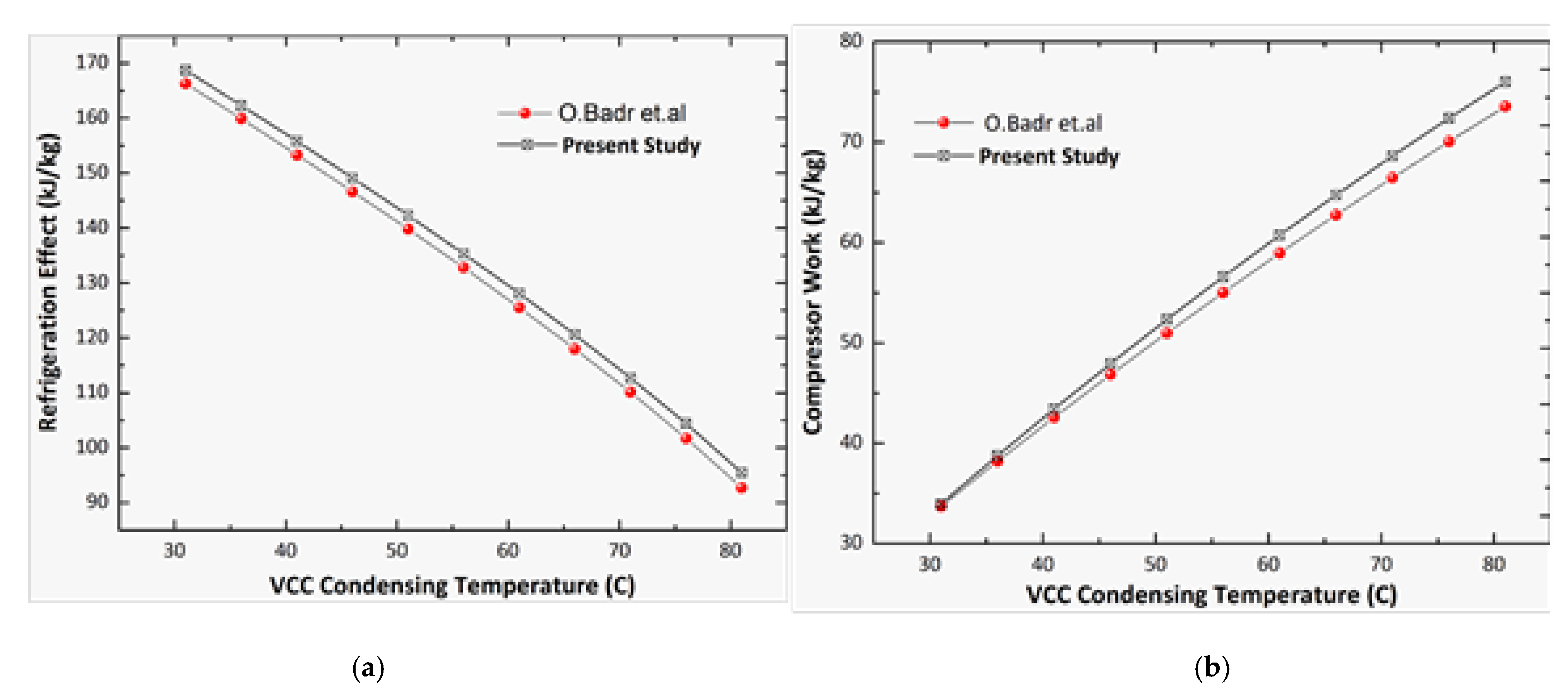
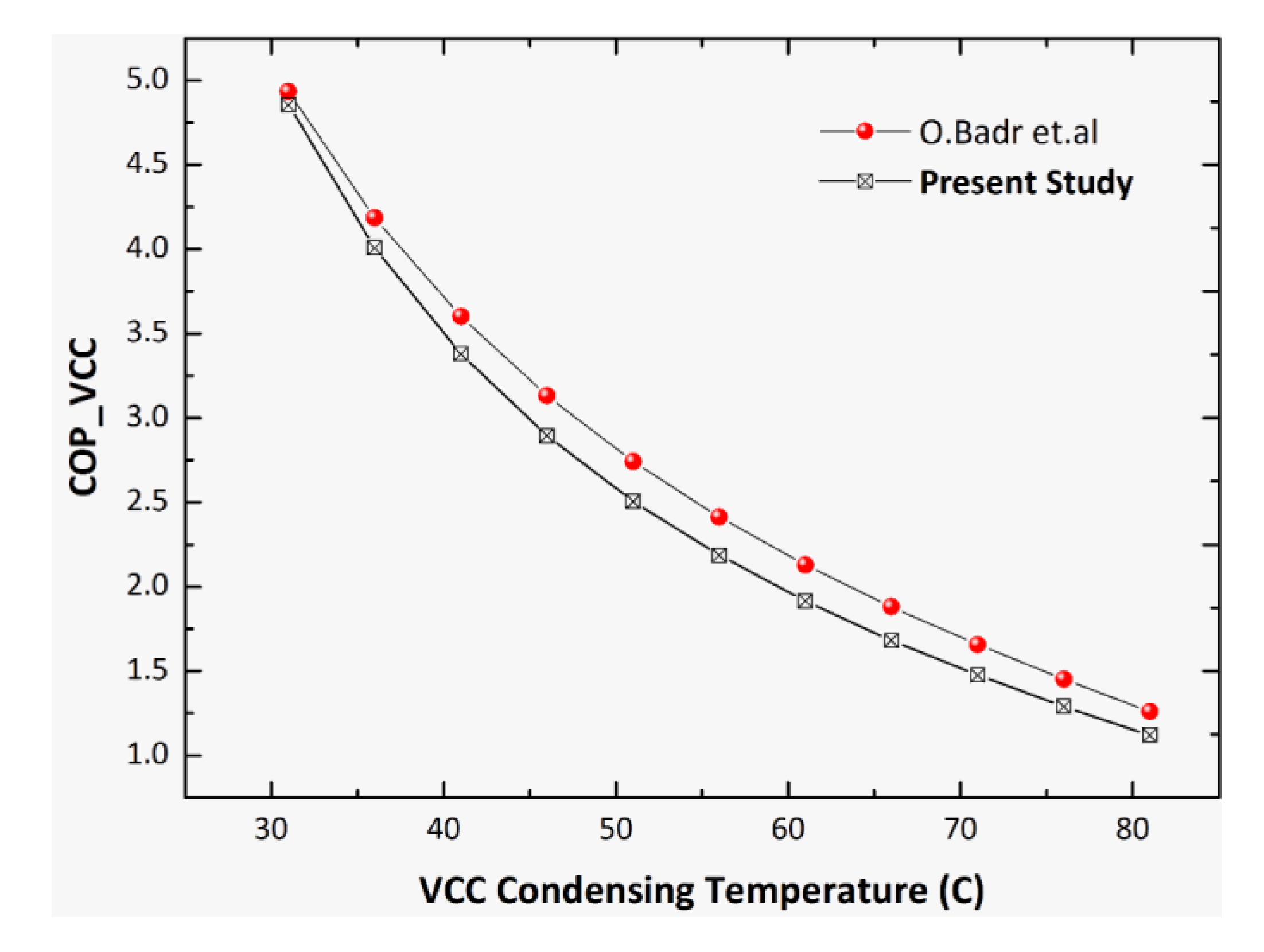
2.3. Model Validation

The thermodynamic model is validated against the existing models in the literature for VCC and ORC applications to ensure its viability. Since the validation of the integrated model is not possible, the VCC and ORC are validated individually from the literature published in the past. The VCC model is validated for an isentropic refrigerant R22 for the conditions presented in O. Badr et al. [27], whereas the ORC model is validated from B.F. Tchanche [28].
The validation results of the present VCC system against those in O. Badr et al. [27] for the COP of the standalone VCC, compressor work and refrigeration effect are shown in Figure 3 and Figure 4. The operating conditions in this case are a VCC condensing temperature = 40 °C, compressor isentropic efficiency = 70% and evaporating temperature = −20 °C. Moreover, the temperature differences for the evaporator and high-temperature reservoir and between the condenser and low-temperature reservoir are kept constant at 5 °C. The VCC system is validated for the VCC condensing temperature against the VCC COP, compressor work and refrigeration effect for the isentropic refrigerant R22.
Similarly, for the validation of the ORC model, three different dry (RC318, R114, R600) and isentropic refrigerants (R141b, R123) are selected, and they are compared with the present study for a 2 kW power output. The input data for model verification are also presented in Table 3. The validation of the model is carried out by comparing the pressures at the inlet and outlet of the expander (Pmin and Pmax), mass flow rate of the working fluid (mwf), thermal efficiency, exergy efficiency and total exergy destruction in the ORC system. The results are presented in Table 4. The results of the ORC subsystem show the close variation with the results published in B.F. Tchanche [28] with a percentage variation ranging from 3 to 6.5%. So, the validated models can now be integrated for ultra-low-grade waste heat recovery.

2.4. Component Sizing

The individual component of the ORC system is designed by the 1-D modeling approach.

2.4.1. Evaporator and Condenser Model

The evaporator and condenser were the brazed plate heat exchanger and were selected due to their compact size. The evaporator and condenser design models were based on a one-dimensional discretization in the flow direction, assuming equidistant steps of an enthalpy rate change for both the fluids. The heat transfer and pressure drop in each control element were calculated by solving the heat transfer and fluid flow conditions for each control volume. The temperatures for the heat transfer calculations were estimated at the control volume center points, interpolating the values between the nodes. The inlet and outlet conditions (temperature and mass flow rate) of the primary and secondary fluid were taken as the input from the cycle design. For a selected heat exchanger geometry, the model is initiated with an assumed number of plates. The design algorithm is iterative and calculates the required number of plates that satisfy the required heat load and pressure drop restriction. The single phase Nusselt Number correlation for water in the brazed plate heat exchanger [29] is given as
N u w = 0.724 ( 6 β π ) 0.646 R e 0.583 P r 0.33
The single phase heat transfer for the ORC working fluid in the plate heat exchanger [30] is given by
α r , s p = 0.292 ( k f D h ) R e 0.78 P r 0.33 ( μ m μ w a l l ) 0.14
The single phase frictional pressure drop factor for both the hot and cold side [29] is calculated as
f = 0.572 R e 0.217
The two phase frictional factor [31] is given by
f i = G e 3 R e e q G e 4
whereas Ge3 and Ge4 are constants given by
G e 3 = 64 , 710 ( P c o D h ) 5.27 ( π 2 β ) 3.03 ;
  G e 4 = 1.314 ( P c o D h ) 0.62 ( π 2 β ) 0.47
The heat transfer coefficient of the water side is calculated as
N u w = 0.724 ( 6 β π ) 0.646 R e 0.583 P r 0.33
The condenser model is the same as that of the evaporator model except for the heat transfer and pressure drop correlations. The single-phase heat transfer and pressure drop correlations are the same as for the evaporator, while the working fluid condensation heat transfer coefficient in the plate heat exchanger is given by [32]
N u = G e 5 G e e q G e 6 B o e q 0.3 P r 0.4
where Ge5 and Ge6 are constants given by
G e 5 = 11.22 ( P c o D h ) 0.041 ( π 2 β ) 4.5
G e 6 = 0.35 ( P c o D h ) 0.23 ( π 2 β ) 1.48
The two phase frictional factor for the condensation pressure drop [32] is given by
f = G e 7 R e e q G e 8
where the Ge7 and Ge8 are constants given by
G e 7 = 3521 ( P c o D h ) 4.17 ( π 2 β ) 7.75 ;   G e 8 = 1.024 ( P c o D h ) 0.0925 ( π 2 β ) 1.3

2.4.2. Expander Model

In this system, the expander model was developed based on Stodola’s ellipse approach [32]. The inlet pressure depends on flow characteristics and is given by the following.
φ o f f = m f , o f f T i n , o f f P i n , o f f ˙
φ o f f φ d = 1 [ P o u t ,   o f f P i n , o f f ] 2 1 [ P o u t , d P i n , d ] 2
Specifically, the inlet pressure under the off-design condition is given b
P i n , o f f = m f , o f f 2 × T i n , o f f × Y d + P o u t , o f f 2 ˙
where Yd is given by
Y d = P i n , d 2 P o u t , d 2 P i n , d 2 × φ d 2
The expander model is based on an isentropic efficiency of 70%.

2.4.3. Pump Model

Based on the system hydraulic characteristics and pump affinity law, the pump was modeled. According to the pump affinity law:
m f , o f f ˙ m ˙ f , d = R P M o f f R P M d   a n d   H o f f H d = [ R P M o f f R P M d ] 2
By a comparison of the above equations:
H o f f H d = [ m f , o f f ˙ m f , d ] 2

3. Results and Discussion

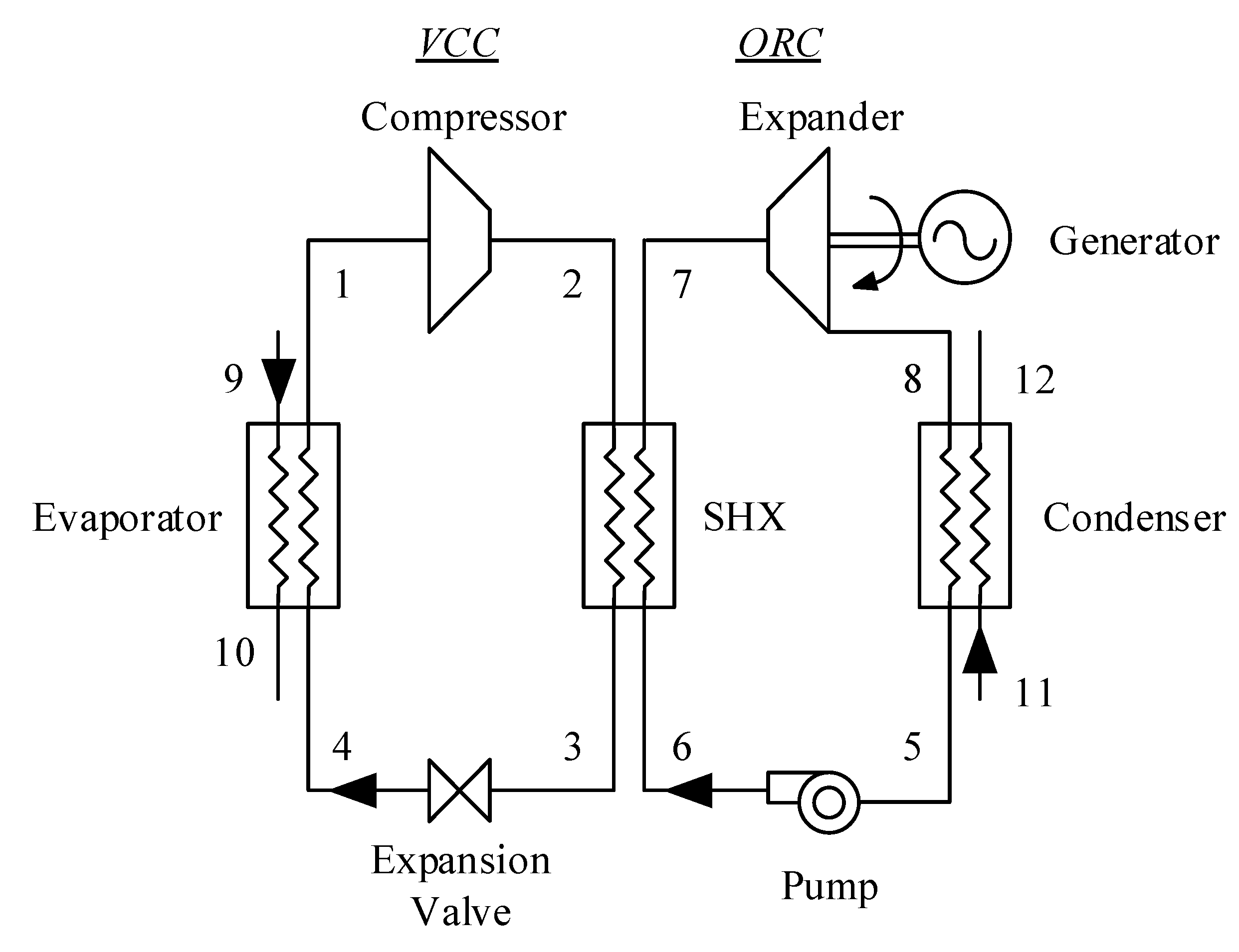
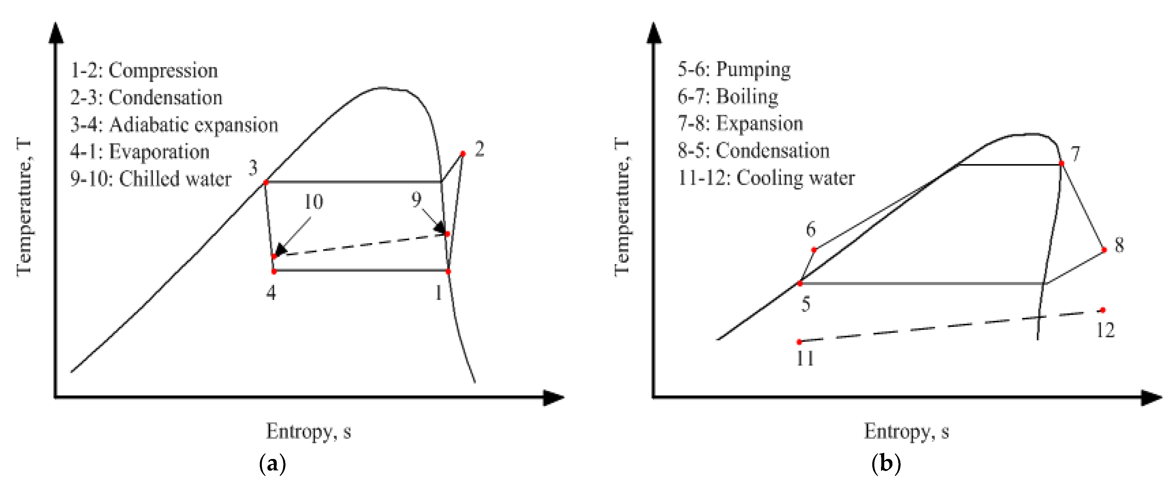
Integrated VCC-ORC System-Recovery of Heat from VCC Condenser

The energetic and exergetic analysis of the integrated VCC-ORC system by the full heat rejection recovery approach is shown in Table 5. A total of 36 combinations of different fluids were simulated in EES to find out the best candidate of the fluid pair in the integrated system. Amongst different combinations, R600a-R141b is the best choice considering the performance indexes of the Net COP (3.54), ORC thermal efficiency (3.05%), electricity saving ratio (13.34%) and total exergy destruction (6.94 kW). The COP is improved by 12.5% by integrating the ORC as compared to the COP of the standalone VCC system (3.09). The results for the selected optimum fluid pair (R600a-R141b) for variable conditions are shown in Figure 5, Figure 6, Figure 7 and Figure 8. The designed VCC condensation temperature, condensing water temperature, mass flow rate of condensing water and return chilled water temperature are plotted against the Net COP, net electricity, exergy efficiency and system exergy destruction to study the trend of the optimum selected working fluid (R600a-R141). Figure 5a shows that the net COP (3.54) and net electricity (1.41 kW) have the optimum value at a VCC condensation temperature of 50 °C.
If the VCC condensation temperature is reduced below 50 °C, then there will be an increase in the net COP by 8% for every 5 °C drop in the VCC condensation temperature.
The i-VCC-ORC exergy efficiency decreases with an increase in the VCC condensation temperature as shown in Figure 5b. For every 5 °C increase in the designed VCC condensation temperature, the net exergy efficiency of the system decreases by 9%. It has a value of 23.78% at a condensation temperature of 40 °C, reduces to 21.65% at 45 °C and has a value of 15.97% at 60 °C. The system exergy destruction showed an increase of 7% for every 5 °C increase in the condensation temperature.
Figure 6 shows the trend of the condensing water temperature against the net COP, net electricity, exergy efficiency and system exergy destruction. At a condensing water temperature of 25 °C, the fluid pair has a maximum net COP of 3.73 and net electricity production of 1.924 kW. If we analyze the system response by decreasing the condensing water temperature, then the net COP and net electricity production increase, whereas there is a very slight decrease in the i-VCC-ORC exergy efficiency with an increase in the condensing water temperature. If the condensing water temperature is 25 °C, the net COP and net electricity values show the values of 3.73 and 1.92 kW.
Similarly, Figure 7a shows the trend of the changing mass flow rate of the condensing water against the same parameters for the selected fluid pair. At a designed mass flow rate of 4 kg/s, the net COP and net electricity values are 3.56 and 1.46 kW, respectively. In Figure 7b, the variation of the i-VCC-ORC exergy efficiency with the mass flow rate shows an almost constant value with little variation between 19 and 20%. The trend of the system exergy destruction shows that it decreases in the beginning, and then it starts to increase with increasing mass flow rates.
Figure 8a shows the trend of the net COP and net electricity with a changing return chilled water temperature. The net COP values ranges from 3.43 to 3.65 with a value of 3.54 at a return chilled water temperature of 12 °C. Similarly, the variation of net electricity is almost the same, ranging from 1.413 to 1.411 kW with a value of 1.41 kW at 12 °C. With an increase in the return chilled temperature, both the ORC exergy efficiency and i-VCC-ORC exergy efficiency decrease slightly with an increase in the system exergy destruction as shown in Figure 8b.

4. Conclusions

In this study, the novel integrated vapor compression cycle and organic Rankine cycle (i-VCC-ORC) system are presented. A performance assessment and selection of the best working fluid were evaluated for a vapor compression system of a 10-ton (35 kW) refrigeration capacity (heat input). The organic Rankine cycle recovers the waste heat from the condenser of the refrigeration cycle for electricity production. The heat rejected form the VCC condenser is fully recovered by the ORC using a shared heat exchanger for waste heat utilization.
From the analysis, R600a-R141b was found to be the most suitable working fluid with a net COP of 3.54, an ORC thermal efficiency of 3.05% with an exergy efficiency of 19.64% and a net electricity output of 1.41 kW. The integrated VCC-ORC system improved the COP by 12.5% as compared to the standalone system. The sensitivity analysis of the system shows that
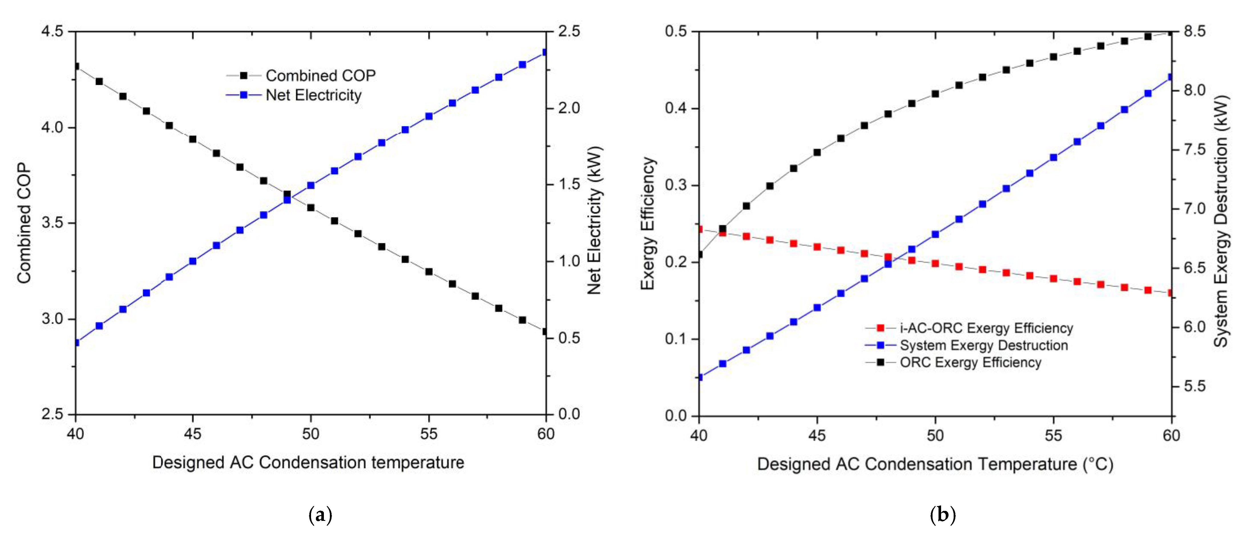
  • As the designed VCC condensation temperature increases, there is an increase in net electricity production, system exergy destruction and ORC exergy efficiency, whereas the net COP and system exergy efficiency decrease.
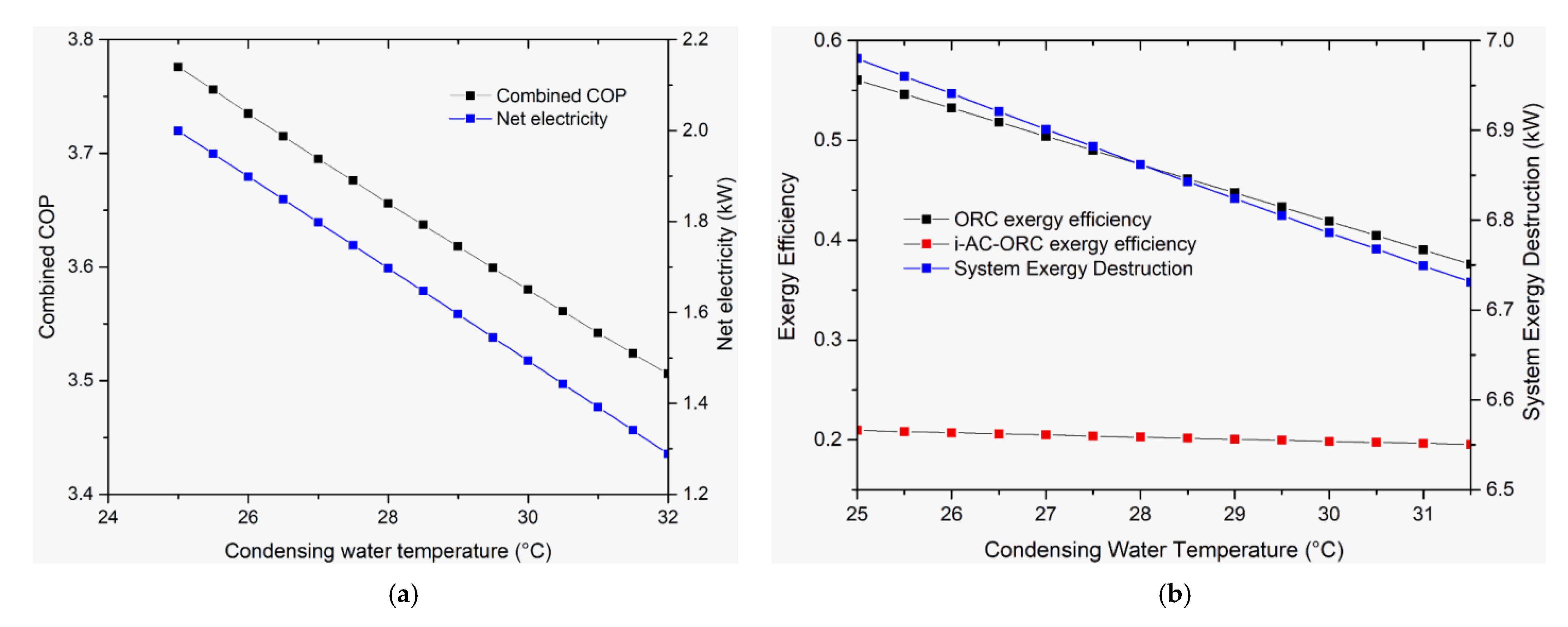
  • With an increase in the condensing water temperature, the net electricity and net COP show a linear decline. Similarly, the system exergy efficiency and system exergy destruction also decrease as the condensing water temperature decreases.
  • When the mass flow rate of the condensing water increases, there is an increase in the net COP, net electricity, ORC exergy efficiency and system exergy destruction, whereas there is a slight increase in the system exergy efficiency with an increasing mass flow rate.
  • With an increasing return chilled water temperature, the net COP, net electricity and system exergy destruction increase, while the exergy efficiency decreases.

Author Contributions

Conceptualization, M.A. and M.K.H.L.; methodology, M.A. and F.K.; software, M.A. and M.I.; validation, M.A., J.Z.A. and A.W.Z.; formal analysis, J.U., S.K. and M.A.; investigation, M.A.; resources, M.A., M.K.H.L. and M.I.; data curation, M.A.; writing—original draft preparation, M.A., M.I., A.W.Z.; writing—review and editing, M.A., J.U., A.W.Z., J.Z.A. and S.K.; visualization, M.A. and M.I.; supervision, M.K.H.L.; project administration, M.A.; funding acquisition, M.A. and M.I. All authors have read and agreed to the published version of the manuscript.

Funding

The work described in this paper was partially supported by the Research Grants Council of the Hong Kong Special Administrative Region, China (Project No.: UGC/IDS(R)24/20), (Project Ref No. SEHS-2020-204(I)) and from Jiangsu Provincial Government Research Funding (Project No.: 2021K101B).

Institutional Review Board Statement

Not applicable.

Informed Consent Statement

Not applicable.

Data Availability Statement

Not applicable.

Acknowledgments

The authors would like to thank the Research Grants Council Hong Kong Special Administrative Region, China and School of Professional Education & Executive Development, The Hong Kong Polytechnic University for their support. The authors thank anonymous referees for their insightful comments.

Conflicts of Interest

The authors declare no conflict of interest.

Nomenclature

aheat transfer coefficient: W/m2Kcfcold fluid
combcombined
Aheat transfer area, m2compcompressor
Boboiling numbercondcondenser
Dhhydraulic diameter, mcrcritical
Eelectricity, kWevapevaporator
Gmass flux, kg/m2seqequivalent
Ge1, Ge2correlation coefficientsexexergy
hspecific enthalpy, kJ/kgfsaturated liquid
ifgenthalpy of vaporization, J/kgggenerator
kthermal conductivity, W/mKhfhot fluid
mmass flow rate, kg/siregion part
Mmolar mass, kg/kmoliniinitial
NuNusselt numberlliquid
Ppressure, MPamaverage value for the two-phase mixture
Pcoheat exchanger pitchrrefrigerant
PrPrandtl numberrecorecovery
qheat flux, W/m2expexpander
Qenergy, kWvsaturated vapor
ReReynolds numbervalveexpansion valve
sspecific entropy, kJ/(kg·K)
Ttemperature, °C
T0dead state temperature, K
Vvolumetric flow rate, m3/sAcronyms
Wpower, kW
xvapor qualityGWPglobal warming potential
i-VCC-ORCIntegrated vapor compression cycle-organic Rankine cycle
Greek symbols
ηefficiency
βchevron angle, radianODPozone depletion potential
μdynamic viscosity, Ns/m2SHXshared heat exchanger
Subscripts WHRwaste heat recovery
1-12state points

References

  1. Moles, F.; Navarro-Esbrí, J.; Peris, B.; Mota-Babiloni, A.; Kontomaris, K. Kostas, Thermodynamic analysis of a combined organic Rankine cycle and vapor compression cycle system activated with low temperature heat sources using low GWP fluids. Appl. Therm. Eng. 2015, 87, 444–453. [Google Scholar] [CrossRef]
  2. Imran, M.; Usman, M.; Yang, Y.; Park, B.-S. Flow boiling of R245fa in the brazed plate heat exchanger: Thermal and hydraulic performance assessment. Int. J. Heat Mass Transf. 2017, 110, 657–670. [Google Scholar] [CrossRef]
  3. Quoilin, S. Sustainable Energy Conversion through the Use of Organic Rankine Cycles for Waste Heat Recovery and Solar Applications. Ph.D. Thesis, University of Liège, Liège, Belgium, 2011. [Google Scholar]
  4. Baral, S.; Kim, D.; Yun, E.; Kim, K.C. Energy, Exergy and Performance Analysis of Small-Scale Organic Rankine Cycle Systems for Electrical Power Generation Applicable in Rural Areas of Developing Countries. Energies 2015, 8, 684–713. [Google Scholar] [CrossRef] [Green Version]
  5. Yun, E.; Kim, D.; Yoon, S.Y.; Kim, K.C. Experimental investigation of an organic Rankine cycle with multiple expanders used in parallel. Appl. Energy 2015, 145, 246–254. [Google Scholar] [CrossRef]
  6. Katili, A.; Boukhanouf, R.; Wilson, R. Space Cooling in Buildings in Hot and Humid Climates—A Review of the Effect of Humidity on the Applicability of Existing Cooling Techniques. In Proceedings of the 14th International Conference on Sustainable Energy Technologies, Nottingham, UK, 25–27 August 2015; pp. 25–27. [Google Scholar]
  7. Hong Kong Government. Hong Kong End User Data Report 2017. 2017. Available online: http://www.enb.gov.hk/sites/default/files/pdf/ClimateChangeEng.pdf (accessed on 26 February 2018).
  8. Prigmore, D.; Barber, R. Cooling with the sun’s heat Design considerations and test data for a Rankine Cycle prototype. Sol. Energy 1975, 17, 185–192. [Google Scholar] [CrossRef]
  9. Nasir, M.T.; Kim, K.C. Working fluids selection and parametric optimization of an Organic Rankine Cycle coupled Vapor Compression Cycle (ORC-VCC) for air conditioning using low grade heat. Energy Build. 2016, 129, 378–395. [Google Scholar] [CrossRef]
  10. Nasir, M.T.; Ali, M.A.; Khan, T.S.; Al-Hajri, E.; Kadri, M.B.; Kim, K.C. Performance assessment and multi objective optimization of an Organic Rankine Cycle driven cooling air conditioning system. Energy Build. 2019, 191, 13–30. [Google Scholar] [CrossRef]
  11. Nasir, M.T.; Ekwonu, M.C.; Esfahani, J.A.; Kim, K.C. Performance assessment and multi-objective optimization of an organic Rankine cycles and vapor compression cycle based combined cooling, heating, and power system. Sustain. Energy Technol. Assess. 2021, 47, 101457. [Google Scholar] [CrossRef]
  12. Asim, M.; Leung, M.K.; Shan, Z.; Li, Y.; Leung, D.Y.; Ni, M. Thermodynamic and Thermo-economic Analysis of Integrated Organic Rankine Cycle for Waste Heat Recovery from Vapor Compression Refrigeration Cycle. Energy Procedia 2017, 143, 192–198. [Google Scholar] [CrossRef]
  13. Bao, J.; Zhang, L.; Song, C.; Zhang, N.; Zhang, X.; He, G. Comparative study of combined organic Rankine cycle and vapor compression cycle for refrigeration: Single fluid or dual fluid? Sustain. Energy Technol. Assess. 2020, 37, 100595. [Google Scholar] [CrossRef]
  14. Aphornratana, S.; Sriveerakul, T. Analysis of a combined Rankine–vapour–compression refrigeration cycle. Energy Convers. Manag. 2010, 51, 2557–2564. [Google Scholar] [CrossRef]
  15. Kim, K.H.; Perez-Blanco, H. Performance analysis of a combined organic Rankine cycle and vapor compression cycle for power and refrigeration cogeneration. Appl. Therm. Eng. 2015, 91, 964–974. [Google Scholar] [CrossRef]
  16. Toujani, N.; Bouaziz, N.; Chrigui, M.; Kairouani, L. The Impact of Operating Parameters on the Performance of a New ORC–VCC Combination for Cogeneration. Therm. Eng. 2020, 67, 660–672. [Google Scholar] [CrossRef]
  17. Saleh, B. Parametric and working fluid analysis of a combined organic Rankine-vapor compression refrigeration system activated by low-grade thermal energy. J. Adv. Res. 2016, 7, 651–660. [Google Scholar] [CrossRef] [Green Version]
  18. Kim, D.K.; Lee, J.S.; Kim, J.; Kim, M.S.; Kim, M.S. Parametric study and performance evaluation of an organic Rankine cycle (ORC) system using low-grade heat at temperatures below 80 °C. Appl. Energy 2017, 189, 55–65. [Google Scholar] [CrossRef]
  19. Javanshir, N.; Mahmoudi, S.M.S.; Rosen, M.A. Thermodynamic and Exergoeconomic Analyses of a Novel Combined Cycle Comprised of Vapor-Compression Refrigeration and Organic Rankine Cycles. Sustainability 2019, 11, 3374. [Google Scholar] [CrossRef] [Green Version]
  20. Zhao, P.; Wang, J.; Gao, L.; Dai, Y. Parametric analysis of a hybrid power system using organic Rankine cycle to recover waste heat from proton exchange membrane fuel cell. Int. J. Hydrog. Energy 2012, 37, 3382–3391. [Google Scholar] [CrossRef]
  21. Liang, Y.; Yu, Z.; Li, W. A Waste Heat-Driven Cooling System Based on Combined Organic Rankine and Vapour Compression Refrigeration Cycles. Appl. Sci. 2019, 9, 4242. [Google Scholar] [CrossRef] [Green Version]
  22. Lakew, A.A.; Bolland, O. Working fluids for low-temperature heat source. Appl. Therm. Eng. 2010, 30, 1262–1268. [Google Scholar] [CrossRef]
  23. Kumar, R.; Memon, A.G.; bin Tariq, A.; Yousfani, F.M. Energy Analysis and Working Fluid Selection of Combined ORC-VCC Refrigeration System Operated by Low-Grade Thermal Energy Sources. In Proceedings of the 2021 4th International Conference on Energy Conservation and Efficiency (ICECE), Lahore, Pakistan, 16–17 March 2021; pp. 1–6. [Google Scholar] [CrossRef]
  24. Habibzadeh, A.; Rashidi, M.M.; Galanis, N. Analysis of a combined power and ejector-refrigeration cycle using low temperature heat. Energy Convers. Manag. 2013, 65, 381–391. [Google Scholar] [CrossRef]
  25. Bao, J.; Zhao, L. A review of working fluid and expander selections for organic Rankine cycle. Renew. Sustain. Energy Rev. 2013, 24, 325–342. [Google Scholar] [CrossRef]
  26. Feng, Y.; Hung, T.; Greg, K.; Zhang, Y.; Li, B.; Yang, J. Thermoeconomic comparison between pure and mixture working fluids of organic Rankine cycles (ORCs) for low temperature waste heat recovery. Energy Convers. Manag. 2015, 106, 859–872. [Google Scholar] [CrossRef]
  27. Badr, O.; O’callaghan, P.W.; Probert, S.D. Vapour-Compression Refrigeration Systems. 1990. Available online: https://ac.els-cdn.com/030626199090004W/1-s2.0-030626199090004W-main.pdf?_tid=383449b4-ae49-4001-b4e9-a218dcb8c9e6&acdnat=1537780829_f4803544debe59e8b9943b9de51d1182 (accessed on 24 September 2018).
  28. Tchanche, B.F.; Papadakis, G.; Lambrinos, G.; Frangoudakis, A. Fluid selection for a low-temperature solar organic Rankine cycle. Appl. Therm. Eng. 2009, 29, 2468–2476. [Google Scholar] [CrossRef] [Green Version]
  29. Imran, M.; Usman, M.; Park, B.-S.; Yang, Y. Comparative assessment of Organic Rankine Cycle integration for low temperature geothermal heat source applications. Energy 2016, 102, 473–490. [Google Scholar] [CrossRef]
  30. Hsieh, Y.; Lin, T. Saturated flow boiling heat transfer and pressure drop of refrigerant R-410A in a vertical plate heat exchanger. Int. J. Heat Mass Transf. 2002, 45, 1033–1044. [Google Scholar] [CrossRef]
  31. Selvam, M.A.J.; Kumar, P.S.; Muthuraman, S. The characteristics of brazed plate heat exchangers with different chevron angles. J. Eng. Appl. Sci. 2009, 4, 19–26. [Google Scholar] [CrossRef]
  32. Han, D.-H.; Lee, K.-J.; Kim, Y.-H. The Characteristics of Condensation in Brazed Plate Heat Exchangers with Different Chevron Angles. J. Korean Phys. Soc. 2003, 43, 66–73. [Google Scholar]
Figure 1. i-VCC-ORC system for recovery of full heat rejection.
Sustainability 13 11592 g001
Figure 2. T-s diagrams of (a) vapor compression cycle and (b) Organic Rankine cycle.
Sustainability 13 11592 g002
Figure 3. (a) VCC Condensing temperature vs. Refrigeration effect for R22; (b) Condensing temperature vs. Compressor work for R22.
Sustainability 13 11592 g003
Figure 4. VCC condensing temperature vs. VCC COP for R22.
Sustainability 13 11592 g004
Figure 5. (a) Designed VCC condensation temperature vs. Net COP and Net electricity, (b) Designed VCC condensation temperature vs. Exergy Efficiency and System exergy destruction.
Sustainability 13 11592 g005
Figure 6. (a) Condensing water temperature vs. Net COP and Net electricity, (b) Condensing water temperature vs. Exergy Efficiency and System exergy destruction.
Sustainability 13 11592 g006
Figure 7. (a) Mass flow rate of condensing water vs. Net COP and Net electricity, (b) Mass flow rate of condensing water vs. Exergy Efficiency and System exergy destruction.
Sustainability 13 11592 g007
Figure 8. (a) Return chilled water temperature vs. Net COP and Net electricity, (b) Return chilled water temperature vs. Exergy Efficiency and System exergy destruction.
Sustainability 13 11592 g008
Table 1. Main properties of the working fluids [21,22].
SystemWorking FluidsM (kg/kmol)Tcr (°C)Pcr (MPa)ODPGWP (for 100 Years)
VCCR134a102.03101.14.0601430
R29044.1096.74.25020
R404A97.6072.03.7203900
R407C86.2085.84.6001800
R600a58.12134.73.63020
R410A72.5870.54.8102100
ORCButane58.12152.03.80020
R123152.93183.73.660.0277
R141b116.95204.44.210.12725
R227ea170.03102.83.0003220
R245fa134.05154.03.6501030
R1233zd(e)130.49166.53.620.000347
VCC = vapor compression cycle; ORC = organic Rankine cycle; ODP = Ozone depletion potential; GWP = Global warming.
Table 2. Design parameters for i-VCC-ORC system.
ParametersUnitsValues
Heat input to VCC systemkW35
Return chilled water temperature°C12
Condensing water temperature°C30
VCC condensation temperature°C50
ORC condensation temperature°C35
Indoor air temperature°C25
Ambient air temperature°C35
Dead state temperature°C25
VCC evaporator pinch point°C06
ORC condenser pinch point°C03
Mass flow rate of condensing waterkg/s4
Mass flow rate of chilled waterkg/s1.7
Return chilled water pressureMPa0.101
Inlet cooling water pressureMPa0.101
Indoor air pressureMPa0.101
Compressor efficiency[%]70
Expander efficiency[%]80
Pump efficiency[%]80
Generator efficiency[%]95
Table 3. Input data for ORC model verification.
Evaporation TemperatureTe75 °C
Condensing temperatureTc35 °C
Expander isentropic efficiencyηexp0.70
Pump efficiencyηp0.80
Expander mechanical efficiencyηmt0.63
Table 4. ORC Validation results.
RefrigerantTypeComparisonPminPmaxmwfThermal Efficiency% Variation
kPakPakg/s%%
RC318DryB.F. Tchanche et al.42512010.3813.7154.76
Present Study41710140.5713.538
R114DryB.F. Tchanche et al.2908260.3054.1226.59
Present Study2497060.3633.850
R600DryB.F. Tchanche et al.3299070.1084.2364.95
Present Study3258820.1124.446
R141bIsentropicB.F. Tchanche et al.1123710.1734.5263.18
Present Study1123580.1734.670
R123IsentropicB.F. Tchanche et al.1304310.2274.4573.66
Present Study1304160.2264.620
Table 5. Energy and exergy analysis of i-VCC-ORC system.
VCC
Working Fluid
ORC
Working Fluid
COPiniCOPnet E n e t ˙
(kW)
ESR
(%)
η t h , O R C
(%)
η e x , O R C
(%)
η e x , A C
(%)
Integrated System
η e x
(%)
I ˙ t o t a l , d
(kW)
R134aButane3.013.421.4012.043.0037.5816.7219.007.28
R1233.013.431.4212.223.0438.1316.7219.047.26
R141b3.013.431.4212.213.0438.1216.7219.047.25
R227ea3.013.401.3411.532.8736.0016.7218.907.36
R245fa3.013.431.4012.083.0137.7116.7219.017.28
R1233zd(e)3.013.431.4112.113.0237.8016.7219.027.27
R290Butane2.933.321.4011.522.9837.4916.2918.467.6
R1232.933.331.4311.683.0338.0416.2918.497.57
R141b2.933.331.4311.663.0338.0216.2918.497.56
R227ea2.933.311.3511.042.8635.9216.2918.367.67
R245fa2.933.331.4111.563.0037.6116.2918.477.59
R1233zd(e)2.933.331.4111.583.0137.7116.2918.477.58
R404AButane2.562.861.478.663.0137.1214.2015.909.22
R1232.562.871.498.773.0537.6714.2015.939.19
R141b2.592.871.498.753.0637.6614.2015.939.18
R227ea2.562.851.408.752.8935.5614.2015.829.30
R245fa2.562.871.478.683.0237.2514.215.919.21
R1233zd(e)2.562.871.488.73.0337.3414.215.919.20
R407CButane3.073.431.1811.552.5430.4517.0519.037.27
R1233.073.431.2011.712.5830.8517.0519.057.25
R141b3.073.431.1911.72.5830.8217.0519.057.24
R227ea3.073.411.1411.082.4529.3317.0518.957.33
R245fa3.073.431.1811.582.5530.5417.0519.037.27
R1233zd(e)3.073.431.1910.952.5630.6117.0519.047.26
R600aButane3.103.531.4013.143.0038.7317.1919.606.98
R1233.103.541.4113.283.0539.3017.1919.646.96
R141b3.103.541.4113.343.0539.2917.1919.646.94
R227ea3.103.511.3312.552.8837.1017.1919.497.05
R245fa3.103.531.4013.183.0138.8617.1919.616.97
R1233zd(e)3.103.531.4013.223.0238.9617.1919.626.97
R410AButane2.723.071.449.623.0134.2715.1117.028.44
R1232.723.071.469.753.0634.7715.1117.058.42
R141b2.723.071.469.743.0534.7615.1117.058.41
R227ea2.723.051.389.262.8932.8315.1116.938.53
R245fa2.723.071.459.653.0234.3815.1117.038.44
R1233zd(e)2.723.071.459.673.0334.4715.1117.038.43
Publisher’s Note: MDPI stays neutral with regard to jurisdictional claims in published maps and institutional affiliations.

