Article

Optimized Thin-Film Organic Solar Cell with Enhanced Efficiency

by
Waqas Farooq
1,
Muhammad Ali Musarat
2,*,
Javed Iqbal
1,
Syed Asfandyar Ali Kazmi
1,
Adnan Daud Khan
3,
Wesam Salah Alaloul
2,
Abdullah O. Baarimah
2,
Ashraf Y. Elnaggar
4,
Sherif S. M. Ghoneim
5 and
Ramy N. R. Ghaly
6
1
Department of Electrical Engineering, Sarhad University of Science and Information Technology, Peshawar 25000, Pakistan
2
Department of Civil and Environmental Engineering, Universiti Teknologi PETRONAS, Bandar Seri Iskandar 32610, Perak, Malaysia
3
Center for Advanced Studies in Energy, University of Engineering & Technology, Peshawar 25000, Pakistan
4
Department of Food Nutrition Science (Previously Chemistry), College of Science, Taif University, Taif 21944, Saudi Arabia
5
Department of Electrical Engineering, College of Engineering, Taif University, Taif 21944, Saudi Arabia
6
Mininstry of Higher Education, Mataria Technical College, Cairo 11718, Egypt
*
Author to whom correspondence should be addressed.
Sustainability 2021, 13(23), 13087; https://doi.org/10.3390/su132313087
Submission received: 27 October 2021 / Revised: 11 November 2021 / Accepted: 22 November 2021 / Published: 26 November 2021
(This article belongs to the Section Environmental Sustainability and Applications)

Abstract

:
Modification of a cell’s architecture can enhance the performance parameters. This paper reports on the numerical modeling of a thin-film organic solar cell (OSC) featuring distributed Bragg reflector (DBR) pairs. The utilization of DBR pairs via the proposed method was found to be beneficial in terms of increasing the performance parameters. The extracted results showed that using DBR pairs helps capture the reflected light back into the active region by improving the photovoltaic parameters as compared to the structure without DBR pairs. Moreover, implementing three DBR pairs resulted in the best enhancement gain of 1.076% in power conversion efficiency. The measured results under a global AM of 1.5G were as follows: open circuit voltage (Voc) = 0.839 V; short circuit current density (Jsc) = 10.98 mA/cm2; fill factor (FF) = 78.39%; efficiency (η) = 11.02%. In addition, a thermal stability analysis of the proposed design was performed and we observed that high temperature resulted in a decrease in η from 11.02 to 10.70%. Our demonstrated design may provide a pathway for the practical application of OSCs.

1. Introduction

Harvesting energy from cleaner sources and protecting the environment from harmful gasses are currently the main targets worldwide in order to protect the ozone layer. In this regard, photovoltaic technology plays a significant role in generating energy from thin-film solar cells (TFSC) by absorbing light from endless sources via the sun. Different materials are available with which to produce TFSC. Researchers from various fields have investigated and promoted photovoltaic technology usage in order to remove unwanted gasses from the environment. Additionally, several materials have been optimized and commercialized. Such materials deliver high performance, although they also release toxic waste into the environment. There is a dire need to investigate, extract, and synthesize the materials from sources with low toxicity to obtain a suitable material for TFSC. In the green energy scenario, the organic photovoltaic (OPV) method is leading the charge for TFSC, especially in solar cells, which have tremendous advantages over other semiconducting materials, such as their low production costs, high mechanical flexibility, ability for roll-to-roll (R2R) production, semi-transparency, and light weight [1,2]. Such materials provide a benchmark for producing energy from green sources. Organic solar cells (OSCs) are also known as polymer solar cells (PSCs) because the base material is composed of two components, i.e., a donor material and acceptor material (D/A).
The donor is responsible for holes and the acceptor is responsible for electrons. The combined (D/A) material in OSCs is known as the bulk heterojunction (BHJ), which is placed between the two electrodes. The cells work on the principle of the photovoltaic effect. The roles of the lowest unoccupied molecular orbital (LUMO) and highest unoccupied molecular orbital (HUMO) are considered in OSCs, as shown in Figure 1. The bonded pair (e–h) in OSCs is known as an exciton, which is disassociated by force, whereby (e–h) moves to the respected functional electrode of the device. The ability to absorb a large amount of light even at low light conditions is observed in OSCs, making them prominent materials in the field of PV. A series of materials have been studied in the literature, which have been synthesized and conjugated with other novel materials to improve certain properties by modifying the morphology of the substrate by introducing wide bandgap materials, which improves the device performance [3].
OSCs suffer from low efficiency and low stability at high temperatures, making them less effective in terms of commercialization. The transmittance problem in OSCs is also one of the barriers to their commercialization, which needs to be resolved by injecting effective interfacial layers or by sufficiently reducing this transmittance problem and improving the reflection of light and stability in the active region of the cell. The traditional bottom metal electrode also produces heat, which causes thermalization in the cell and results in a decline in the PV parameters [4,5,6]. DBR pairs are used to replace metal electrodes because metal electrodes in solar cells produce heat, which further generates thermal losses, degrading the performance of the device. Regarding these thermal losses, the DBR plays a significant role not only by reducing the thermalization but also by increasing the electrical photovoltaic performance parameters, for example via high conversion efficiency. However, other approaches utilized to replace metal electrodes only reduce the thermalization but do not significantly impact the device performance parameters. In contrast to this, the DBR pairs increase the cell’s thickness, increasing its height and overall cost; as the thickness increases, more material is utilized, meaning the cost increased [7,8].
Thus, low efficiency is always a hindrance to the commercialization of solar cells. Numerous experimental and theoretical modeling studies have been performed to optimize cells so as to increase performance in this context. The theoretical optimized solar cells provide a great opportunity for experimental investigation and could help determine the device’s inner performance more precisely. Moreover, numerical modeling is considered a cost-effective technique. From the literature, it is observable that the power conversion efficiency rate of a cell can be remarkably improved by utilizing different approaches, such as inverted structure [9], tandem structure [10], optimization by optical admittance analysis method [11], characterization [12], and DBR [8] techniques.
Ourahmoun computationally examined the impacts of different interfacial layers on organic solar cells and optimized the cell performance by delivering a conversion efficiency rate of 5% [13]. Hamed et al. recorded an η of 6.03% from PSCs [14]. Sartorio et al. fabricated OSCs and reported an efficiency rate of 4.46% [15]. Jiang et al. recorded an efficiency rate of 7.07% from PBDBT-T:PDT solar cells [16]. Park et al. fabricated PTB7:PC71BM OSCs and obtained an η of 8.984% [17]. Sun et al. demonstrated an efficiency rate of 9.036% for PTB7:PC71BM-based cells [18]. Muhammad et al. reported an η of 1.06% from the organic solar cells [19]. Wu et al. obtained an efficiency rate of 9.09% from non-fluorine organic solar cells [20]. Kazmi et al. investigated CdTe solar cells and used Si/Al2O3 as DBR pairs, observing a conversion efficiency rate of 23.94% under standard testing conditions of 1.5 AM [8]. Ozen incorporated DBR pairs composed of Si/SiO2 on CdTe solar cells and reported an efficiency rate of 10.39% [21]. Rouhbakhshmeghrazi et al. investigated tandem solar cells based on DBR pairs(SiO2/TiO2) and reported a conversion efficiency rate of 28.5% [22]. Yu et al. used ZnSe/LiF as DBR pairs in semitransparent polymer solar cells and reported a conversion efficiency rate of 6.19% [23].
As follows from the above review, there is no effective non-toxic, single-junction organic solar cell option available based on the DBR technique. This article aims to develop a new single-junction organic solar cell based on the DBR technique. The main objectives are as follows:
  • To achieve high conversion efficiency by optimizing the active layer of the cell;
  • To observe the impact of DBR pairing on the performance of the cell;
  • To observe the impact of high temperature on the cell performance parameters.

2. Materials and Methods

Figure 2 shows the proposed schematic of the cell with a combination of different effective layers. Fluorine tin oxide (FTO) was used as the transparent conductive oxide (TCO) at a thickness of 125 nm as the top electrode. The advantages of using FTO are its high transparency, good thermal stability, and high conductivity. The transparent conductive oxide was utilized because it allows maximum transmission of solar light towards the active region. Next, V2O5 was placed as a hole transport layer (HTL) at a thickness of 30 nm. The benefit of using V2O5 as an HTL layer is that it has an excellent hole transporting ability and has outstanding functionality as an electron blocking layer [24].
Moreover, it has excellent thermal stability. Next to the HTL layer, PTB7:PCBM was introduced as an active layer at a thickness of 180 nm. PTB7:PCBM can absorb many photons even in low light conditions because it has a high absorption coefficient [25] and has a narrow bandgap. In addition, PTB7:PCBM is easy to fabricate, involves low manufacturing costs, and has highly flexible mechanical properties. Thus, PTB7:PCBM is an attractive candidate for thin-film technology because of its high molecular weight of 891.4 and broad absorption coefficient value α of 67,237 cm−1 [26]. For better quenching of electrons, three electron transporting layers (ETL) (i.e., PCBM (10 nm), zinc oxide (ZnO; 5 nm), and tungsten trioxide, WO3 (70 nm) were utilized to improve the transportation of electrons and achieve high conversion efficiency. ZnO was utilized because of its low cost, large binding energy, and much higher electron mobility as compared to other types of oxides such as TiO2. The reason for using WO3 is that it can provide a rapid hopping mechanism for electrons, which further increases the electron mobility, resulting in the collection of enhanced performance parameters [27]. For the back electrode, ZnO-doped silver (Ag) (ZnO:Ag) was used at a thickness of 100 nm. Next, DBR pairs were introduced, namely pairs of WO3 and lithium fluoride (LiF). The reason for using a DBR is that it can reflect the light from the bottom of the cell, and that the reflected light can be reabsorbed in the active layer, which has a significant effect on the cell’s performance [8].
In this investigation, a general-purpose photovoltaic device model (GPVDM) [28] was used to obtain the PV electrical parameters. The software package utilizes the continuity and Poisson equations for calculations and the drift–diffusion model for transport. Moreover, the Shockley–Read–Hall formalism is used for charge carrier recombination and the Scharfetter–Gummel approach is considered for numerical stability.
The Poisson equation is expressed as (1):
d d x ε o ε r . d φ d x = q ( n p )
whereas Equations (2) and (3) represent the drift–diffusion model for holes and electrons, respectively:
J n = q μ c n E c x + q D n n x
J p = q μ c p E v x + q D p p x
Here, D n and D p represent the coefficient of diffusion.
The continuity equation can be written as (4) and (5):
J n x = q ( R n G + n t )
J p x = q ( R p G + p t )
For plane waves, the relation between the magnetic and electric fields can be expressed as (6):
× E = j ω μ H
whereas the wave vector is expressed as (7):
k = 2 ω λ = ω n c

3. Result and Discussion

3.1. Cell Architecture and Active Layer Optimization

The aim here is to understand the underlying photo physics of the cell architecture, optimize the active layer to achieve high conversion efficiency, and utilize DBR pairs to absorb the reflected light back into the active region. Optimizing the active layer not only helps in improving the performance parameters but also helps to reduce the cost of the material. After optimizing the active layer, DBR pairs help enhance the efficiency by reflecting the light towards the photoactive layer. The composition and role of the effective layers are displayed in Table 1.

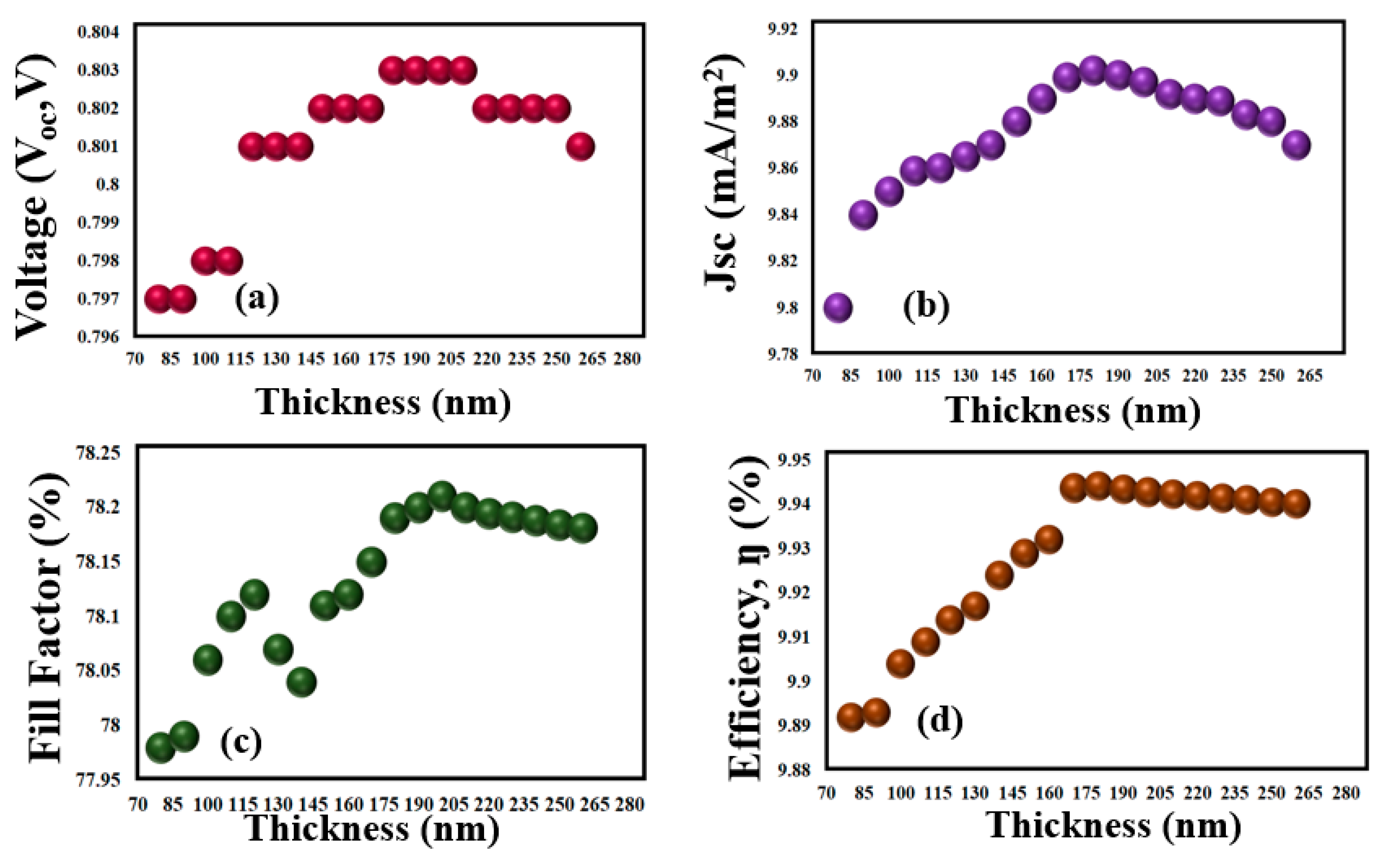
3.2. Optimization of Light-Harvesting Layer (LHL)

The performance of the cell relay on the LHL increased as the incident photons became absorbed in this region. The absorption of photons is the critical aspect of the cell, as the thickness of the LHL is the most crucial aspect of the device architecture. The thickness of the LHL should be very thin [29]. Optimization of the active layer is needed with to reduce the manufacturing costs by utilizing only the optimized amount of layers, which helps in achieving high energy efficiency. The optimization of PTB7:PCBM as the LHL is achieved by modulating its thickness. The thickness of the active region has a direct impact on the performance parameters [30]. Thickness alterations of the active layer are performed between 80–260 nm. As the thickness of the cell increases from 80 nm, the performance parameters, i.e., Voc, Jsc, FF, and η, start improving, as shown in Figure 3a–d, respectively. Equation (8) is considered for the calculation of FF:
F F = J m p V m p J s c V o c
whereas the η of the cell can be calculated by (9):
η = v o c l s c F F P i n p u t × 100
where Pinput is equal to 100 mW/cm2 or 1000 W/m2.
The highest performance parameters are recorded at 180 nm by delivering high values of Voc = 0.803 V, Jsc = 9.902 mA/cm2, FF = 78.19%, and η = 9.944%. Further enhancement in the thickness results decreased cell performance parameters. If the cell is very thin the photons will be lost, while at the same time if it is thick then the photons may not travel in the active region for a long distance because of their low lifetime.
The Jsc of the cell increases by improving the cell thickness, because many photons are absorbed and excitons are created, which helps achieve high values. The FF started decreasing after attaining the optimized thickness of 180 nm because of series resistance, which appeared due to the thick active layer of the cell [31]. The appearance of the bell curve in Figure 3a–d occurred when the film thickness increased, whereby in addition to the e–h pairs increasing, the recombination and defect in the matrix of the cell also increase, causing the bell curve. Moreover, the decrease in the Voc occurred because of the high recombination of electrons and holes. The high recombination of electrons and holes occurred because of the increased defect centers [32], whereby Jsc influences the Voc. Moreover, increased film thickness results in reduced power density. Therefore, a substantial decrease in the PV parameters was obvious.

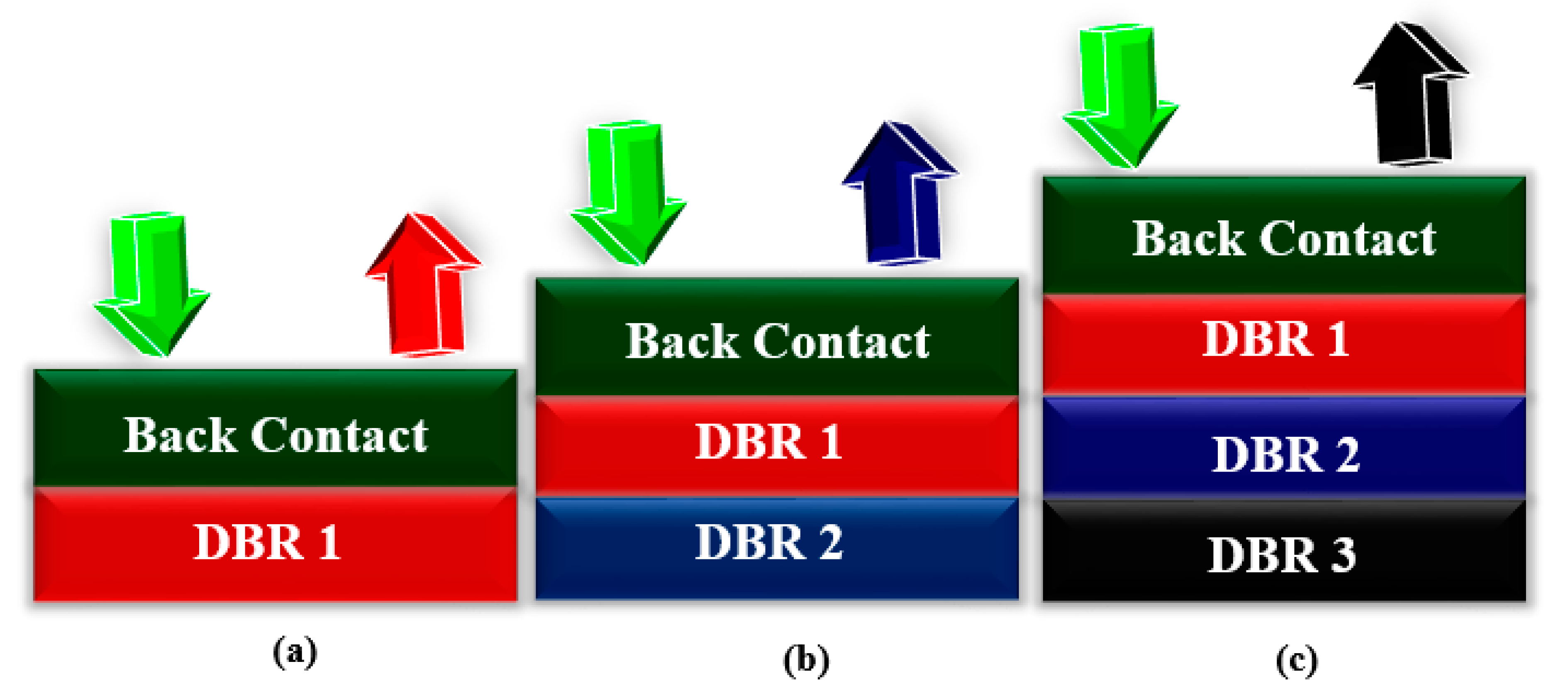
3.3. Implanting DBR Pairs

After optimizing the cell LHL layer, the DBR pairs composed of WO3/LiF were introduced, as shown in Figure 4. The DBR pairs help capture the reflected light back into the active region, increasing the cell’s performance.
The improved performance occurred because of the LHL absorption spectrum matching with the DBR reflectance spectrum. By increasing the number of DBR pairs, the performance parameters, including, Voc, Jsc, FF, and η, started improving. Due to the insertion of the DBR pairs, the Jsc increased from 9.902 to 10.98 mA/cm2, Voc from 0.803 to 0.839 V, FF from 78.19 to 78.38%, and η from 9.944 to 11.02%, as shown in Figure 5a–d, respectively, thereby resulting in an enhancement of 1.07% in η. Thus, triple pairs of DBR were found to be more efficient with the proposed architecture, which further suggests that improved performance parameters can be achieved if a properly optimized layer can be used with DBR pairs.

3.4. Thermal Stability Analysis

The device temperature was increased above 300–400 K to test the sensitivity and thermal stability of the cell under high temperatures. As expected, the performance of the cell degraded and the Voc of the cells appeared to blur from 0.839 to 0.802 V. The decreased value of Voc was because of the material Eg, which became unstable, meaning fluctuation occurred in the reverse saturation current due to the increased device temperature. The variation in the reverse saturation current was because of the concentration of the intrinsic carrier ni, which further depended on the energy of the bandgap Eg, i.e., ni2 = k1 e−Eg/k [33]. Within the context of temperature, Voc is given as:
d ( V o c ) d T = 1 T ( V o c     E g q )
Eg/q in Equation (10) will be greater than Voc, which specifies that any adjustment in Voc due to a temperature increase will be negative, i.e., the value of Voc starts fading as the temperature of the device grows. In the present case, if the Voc of the cell decreases, then the η of the cell also decreases from 11.02 to 10.71%, as shown in Figure 6. Thus, the high temperature negatively impacts the cell and makes it less efficient by deteriorating its performance. The small increase in the value of Jsc under high temperature is because of the band energy, which decreases, and more electron–hole pairs are created [33]. This suggests that this gain in the value of Jsc is so small that it cannot result in any significant improvement in cell performance. It is observable from the results that solar cells appear to be sensitive towards high temperatures. The Jsc of the cell under increased temperature can be calculated using Equation (11):
J s c h v = E g d N p h d h v d ( h v )
A comparison with a similar family of thin-film solar cells is presented in Table 2 to highlight the significane of the structure.

4. Conclusions

To summarize, we improved the performance of OSCs by computationally injecting DBR pairs in the following structure (glass/FTO/V2O5/PTB7:PCBM/PCBM/ZnO/WO3/Ag/DBR). The DBR pairs composed of WO3/LiF helped in achieving the enhancement of 1.076%. Moreover, the performed thermal stability analysis helped in determining the performance of the cells under high temperatures. We showed that under high temperature, the efficiency rate of a cell deteriorates by 0.32%. In addition, the performed analysis of the thermal stability under different operating temperatures suggested that solar cells are sensitive towards high temperatures and decreased performance parameters. The obtained results provide a smooth pathway for thin-film technology that can be utilized for potential applications in solar-based devices.

Author Contributions

Conceptualization, W.F., M.A.M. and J.I.; methodology, W.F., M.A.M., J.I. and A.D.K.; software, A.Y.E., S.S.M.G. and R.N.R.G.; validation, J.I., S.A.A.K., A.D.K. and W.S.A.; formal analysis, W.F., M.A.M., J.I., S.A.A.K. and A.O.B.; investigation, W.F., M.A.M., J.I. and A.D.K.; resources, A.Y.E., S.S.M.G. and R.N.R.G.; data curation, W.F., S.A.A.K. and A.O.B., writing—original draft preparation, W.F., J.I., S.A.A.K. and A.D.K., writing—review and editing, M.A.M. and W.S.A.; supervision, M.A.M., J.I. and A.D.K.; project administration, A.Y.E., S.S.M.G. and R.N.R.G.; funding acquisition, A.Y.E., S.S.M.G. and R.N.R.G. All authors have read and agreed to the published version of the manuscript.

Funding

This study was funded by Taif University Researchers Supporting Project, TURSP-2020/32, Taif University, Taif, Saudi Arabia.

Institutional Review Board Statement

Not applicable.

Informed Consent Statement

Not applicable.

Data Availability Statement

All the data are available within this manuscript.

Acknowledgments

This study was carried out using the facilities and materials of Taif University Research Supporting, TURSP-2020/32, Taif University, Taif, Saudi Arabia.

Conflicts of Interest

The authors declare no conflict of interest.

References

  1. Benghanem, M.; Almohammedi, A. Organic Solar Cells: A Review. In A Practical Guide for Advanced Methods in Solar Photovoltaic Systems; Springer: Berlin/Heidelberg, Germany, 2020; pp. 81–106. [Google Scholar]
  2. Gu, Y.; Liu, Y.; Russell, T.P. Fullerene-Based Interlayers for Breaking Energy Barriers in Organic Solar Cells. ChemPlusChem 2020, 85, 751–759. [Google Scholar] [CrossRef]
  3. Firdaus, Y.; He, Q.; Lin, Y.; Nugroho, F.A.A.; Le Corre, V.M.; Yengel, E.; Balawi, A.H.; Seitkhan, A.; Laquai, F.; Langhammer, C.; et al. Novel wide-bandgap non-fullerene acceptors for efficient tandem organic solar cells. J. Mater. Chem. A 2020, 8, 1164–1175. [Google Scholar] [CrossRef]
  4. Xue, R.; Zhang, J.; Li, Y.; Li, Y. Organic solar cell materials toward commercialization. Small 2018, 14, 1801793. [Google Scholar] [CrossRef]
  5. Cha, H.; Wu, J. Understanding what determines the organic solar cell stability. Joule 2021, 5, 1322–1325. [Google Scholar] [CrossRef]
  6. Zhu, C.; Huang, H.; Jia, Z.; Cai, F.; Li, J.; Yuan, J.; Meng, L.; Peng, H.; Zhang, Z.; Zou, Y.; et al. Spin-coated 10.46% and blade-coated 9.52% of ternary semitransparent organic solar cells with 26.56% average visible transmittance. Sol. Energy 2020, 204, 660–666. [Google Scholar] [CrossRef]
  7. Farooq, W.; Alshahrani, T.; Kazmi, S.A.A.; Iqbal, J.; Khan, H.A.; Khan, M.; Raja, A.A.; Rehman, A.U. Materials optimization for thin-film copper indium gallium selenide (CIGS) solar cell based on distributed braggs reflector. Optik 2021, 227, 165987. [Google Scholar] [CrossRef]
  8. Kazmi, S.A.A.; Khan, A.D.; Khan, A.D.; Rauf, A.; Farooq, W.; Noman, M.; Ali, H. Efficient materials for thin-film CdTe solar cell based on back surface field and distributed Bragg reflector. Appl. Phys. A 2020, 126, 46. [Google Scholar] [CrossRef]
  9. He, Z.; Zhong, C.; Su, S.; Xu, M.; Wu, H.; Cao, Y. Enhanced power-conversion efficiency in polymer solar cells using an inverted device structure. Nat. Photonics 2012, 6, 591–595. [Google Scholar] [CrossRef]
  10. Farooq, W.; Khan, A.D.; Khan, A.D.; Rauf, A.; Khan, S.D.; Ali, H.; Iqbal, J.; Khan, R.U.; Noman, M. Thin-film tandem organic solar cells with improved efficiency. IEEE Access 2020, 8, 74093–74100. [Google Scholar] [CrossRef]
  11. Ompong, D.; Narayan, M.; Singh, J. Optimization of photocurrent in bulk heterojunction organic solar cells using optical admittance analysis method. J. Mater. Sci. Mater. Electron. 2017, 28, 7100–7106. [Google Scholar] [CrossRef]
  12. Murugesan, V.S.; Ono, S.; Tsuda, N.; Yamada, J.; Shin, P.-K.; Ochiai, S. Characterization of organic thin film solar cells of PCDTBT: PC71BM prepared by different mixing ratio and effect of hole transport layer. Int. J. Photoenergy 2015, 2015, 687678. [Google Scholar] [CrossRef]
  13. Ourahmoun, O. Effect of the interfacial materials on the performance of organic photovoltaic cells. Mater. Today Proc. 2021, in press. [Google Scholar] [CrossRef]
  14. Hamed, M.; Oseni, S.O.; Kumar, A.; Sharma, G.; Mola, G.T. Nickel sulphide nano-composite assisted hole transport in thin film polymer solar cells. Solar Energy 2020, 195, 310–317. [Google Scholar] [CrossRef]
  15. Sartorio, C.; Campisciano, V.; Chiappara, C.; Cataldo, S.; Scopelliti, M.; Gruttadauria, M.; Giacalone, F.; Pignataro, B. Enhanced power-conversion efficiency in organic solar cells incorporating copolymeric phase-separation modulators. J. Mater. Chem. A 2018, 6, 3884–3894. [Google Scholar] [CrossRef]
  16. Jiang, P.; Lu, H.; Jia, Q.Q.; Feng, S.; Li, C.; Li, H.B.; Bo, Z. Dihydropyreno [1, 2-b: 6, 7-b′] dithiophene based electron acceptors for high efficiency as-cast organic solar cells. J. Mater. Chem. A 2019, 7, 5943–5948. [Google Scholar] [CrossRef]
  17. Park, S.; Kang, R.; Cho, S. Effect of an Al-doped ZnO electron transport layer on the efficiency of inverted bulk heterojunction solar cells. Curr. Appl. Phys. 2020, 20, 172–177. [Google Scholar] [CrossRef]
  18. Sun, Y.; Wang, M.; Liu, C.; Li, Z.; Fu, D.; Guo, W. Realizing efficiency improvement of polymer solar cells by using multi-functional cascade electron transport layers. Org. Electron. 2020, 76, 105482. [Google Scholar] [CrossRef]
  19. Mohammad, T.; Kumar, V.; Dutta, V. Spray deposited indium doped tin oxide thin films for organic solar cell application. Phys. E Low-Dimens. Syst. Nanostruct. 2020, 117, 113793. [Google Scholar] [CrossRef]
  20. Wu, M.; Shi, L.; Hu, Y.; Chen, L.; Hu, T.; Zhang, Y.; Yuan, Z.; Chen, Y. Additive-free non-fullerene organic solar cells with random copolymers as donors over 9% power conversion efficiency. Chin. Chem. Lett. 2019, 30, 1161–1167. [Google Scholar] [CrossRef]
  21. Özen, Y. The enhancement in cell performance of CdTe-based solar cell with Si/SiO2 distributed Bragg reflectors. Appl. Phys. A 2020, 126, 632. [Google Scholar] [CrossRef]
  22. Rouhbakhshmeghrazi, A.; Madadi, M. Novel Design of polycrystalline CdTe/Si Tandem Solar Cells Using SiO2/TiO2 Distributed Bragg Reflector. Tecciencia 2020, 15, 67–75. [Google Scholar] [CrossRef]
  23. Yu, W.; Fu, X.; Dong, K. Study of semitransparent polymer solar cells with ZnSe/LiF distributed Bragg Reflector. J. Mater. Sci. Mater. Electron. 2021, 32, 13409–13417. [Google Scholar] [CrossRef]
  24. Wang, H.-Q.; Li, N.; Guldal, N.S.; Brabec, C.J. Nanocrystal V2O5 thin film as hole-extraction layer in normal architecture organic solar cells. Org. Electron. 2012, 13, 3014–3021. [Google Scholar] [CrossRef]
  25. Brédas, J.-L.; Norton, J.E.; Cornil, J.; Coropceanu, V. Molecular understanding of organic solar cells: The challenges. Acc. Chem. Res. 2009, 42, 1691–1699. [Google Scholar] [CrossRef]
  26. Stelling, C.; Singh, C.R.; Karg, M.; König, T.A.F.; Thelakkat, M.; Retsch, M. Plasmonic nanomeshes: Their ambivalent role as transparent electrodes in organic solar cells. Sci. Rep. 2017, 7, 42530. [Google Scholar] [CrossRef] [PubMed]
  27. Roy, A.; Bhandari, S.; Ghosh, A.; Sundaram, S.; Mallick, T.K. Incorporating Solution-Processed Mesoporous WO3 as an Interfacial Cathode Buffer Layer for Photovoltaic Applications. J. Phys. Chem. A 2020, 124, 5709–5719. [Google Scholar] [CrossRef] [PubMed]
  28. MacKenzie, R.C.I.; Kirchartz, T.; Dibb, G.F.A.; Nelson, J. Modeling nongeminate recombination in P3HT: PCBM solar cells. J. Phys. Chem. C 2011, 115, 9806–9813. [Google Scholar] [CrossRef]
  29. Khan, A.D.; Iqbal, J.; Rehman, S.U. Polarization-sensitive perfect plasmonic absorber for thin-film solar cell application. Appl. Phys. A 2018, 124, 610. [Google Scholar] [CrossRef]
  30. Kosyachenko, L.; Savchuk, A.; Grushko, E. Dependence of efficiency of thin-film CdS/CdTe solar cell on parameters of absorber layer and barrier structure. Thin Solid Film. 2009, 517, 2386–2391. [Google Scholar] [CrossRef]
  31. Kim, M.-S.; Kim, B.-G.; Kim, J. Effective variables to control the fill factor of organic photovoltaic cells. ACS Appl. Mater. Interfaces 2009, 1, 1264–1269. [Google Scholar] [CrossRef]
  32. Chen, S.; Small, C.E.; Amb, C.M.; Subbiah, J.; Lai, T.-H.; Tsang, S.-W.; Manders, J.R.; Reynolds, J.R.; So, F. Inverted polymer solar cells with reduced interface recombination. Adv. Energy Mater. 2012, 2, 1333–1337. [Google Scholar] [CrossRef]
  33. Khan, A.D.; Khan, A.D. Optimization of highly efficient GaAs–silicon hybrid solar cell. Appl. Phys. A 2018, 124, 851. [Google Scholar] [CrossRef]
  34. Sen, S.; Islam, R. Effect of Different Layers on the Performance of P3HT: PCBM-Based Organic Solar Cell. Braz. J. Phys. 2021, 51, 1661–1669. [Google Scholar] [CrossRef]
  35. Zidan, M.N.; Ismail, T.; Fahim, I.S. Effect of thickness and temperature on flexible organic P3HT: PCBM solar cell performance. Mater. Res. Express 2021, 8, 095508. [Google Scholar] [CrossRef]
  36. Khairulaman, F.L.; Yap, C.C.; Jumali, M.H.H. Improved performance of inverted type organic solar cell using copper iodide-doped P3HT: PCBM as active layer for low light application. Mater. Lett. 2021, 283, 128827. [Google Scholar] [CrossRef]
  37. Bendenia, C.; Merad-Dib, H.; Bendenia, S.; Bessaha, G.; Hadri, B. Theoretical study of the impact of the D/A system polymer and anodic interfacial layer on inverted organic solar cells (BHJ) performance. Opt. Mater. 2021, 121, 111588. [Google Scholar] [CrossRef]
  38. Moujoud, S.; Hartiti, B.; Touhtouh, S.; Rachidy, C.; Belhora, F.; Thevenin, P.; Hajjaji, A. Numerical modeling of copper indium disulfide thin film based solar cells. Opt. Mater. 2021, 122, 111749. [Google Scholar] [CrossRef]
  39. Al-Hattab, M.; Moudou, L.; Khenfouch, M.; Bajjou, O.; Chrafih, Y.; Rahmani, K. Numerical simulation of a new heterostructure CIGS/GaSe solar cell system using SCAPS-1D software. Sol. Energy 2021, 227, 13–22. [Google Scholar] [CrossRef]
  40. Jamal, S.; Khan, A.D.; Khan, A.D. High performance perovskite solar cell based on efficient materials for electron and hole transport layers. Optik 2020, 218, 164787. [Google Scholar] [CrossRef]
  41. Kumar, A. Impact of selenium composition variation in CZTS solar cell. Optik 2021, 234, 166421. [Google Scholar] [CrossRef]
  42. Islam, A.; Islam, S.; Sobayel, K.; Emon, E.; Jhuma, F.; Shahiduzzaman, M.; Akhtaruzzaman, M.; Amin, N.; Rashid, M. Performance analysis of tungsten disulfide (WS2) as an alternative buffer layer for CdTe solar cell through numerical modeling. Opt. Mater. 2021, 120, 111296. [Google Scholar] [CrossRef]
  43. Barman, B.; Kalita, P. Influence of back surface field layer on enhancing the efficiency of CIGS solar cell. Sol. Energy 2021, 216, 329–337. [Google Scholar] [CrossRef]
Figure 1. Working principle for OSCs.
Sustainability 13 13087 g001
Figure 2. Configuration of the proposed structure with different critical layers and an optimized estimated thickness, in which FTO is used as the TCO; V2O5 is used as the HTL; PTB7:PCBM is used as an active layer; PCBM, ZnO, and WO3 are used as ETLs (for extracting the enhanced amount of electrons); ZnO:Ag is used as a back electrode; and DBR pairs are used as back reflectors.
Sustainability 13 13087 g002
Figure 3. Thickness optimization of the performance parameters: (a) optimization of the open circuit voltage (Voc) as a function against the active layer thickness; (b) optimization of the short circuit current density (Jsc) as a function against the active layer thickness; (c) optimization of the fill factor (FF) as a function against the active layer thickness; (d) optimization of the efficiency (η) as a function against active layer thickness.
Sustainability 13 13087 g003
Figure 4. Proposed configuration with DBR pairs: (a) single pair; (b) double pairs; (c) triple pairs.
Sustainability 13 13087 g004
Figure 5. Performance parameters after insertion of DBR pairs composed of (W03/LiF). (a) Voc after insertion of DBR pairs 1, 2, and 3. (b) Jsc after insertion of DBR pairs 1, 2, and 3. (c) FF after insertion of DBR pairs 1, 2, and 3. (d) Lastly, η after insertion of DBR pairs 1, 2, and 3.
Sustainability 13 13087 g005
Figure 6. Thermal stability of PV parameters (Jsc, Vocc, and η) at different operating temperatures.
Sustainability 13 13087 g006
Table 1. Materials thickness, composition, and role.
LayersThickness (nm)CompositionRole
FTO125Transparent Conductive OxideElectrode
V2O570InorganicHTL
PTB7:PCBM180OrganicActive Layer
PCBM10OrganicETL
ZnO5InorganicETL
W0370InorganicETL
Ag100MetalElectrode
DBR450InorganicBack Reflector
Table 2. Comparison of the current study with a similar family of thin-film solar cells with respect to the power conversion efficiency.
RefStrutureMethodJunction Modeη
[34]Substrate/ITO/PEDOT:PSS/P3HT:PCBM/TiOx/AlComputationalSingle5.14
[34]Substrate/ITO/PEDOT:PSS/P3HT:PCBM/PCBM/AlComputationalSingle4.95
[35]PET/ITO/PEDOT:PSS/P3HT:PCBM/AlComputationalSingle4.34
[36]Glass/FTO/ZnO/doped P3HT:PCBM/AgExperimentalSingle4.84
[37]ITO/ZnO/PTB7:PCBM/PEDOT:PSS/AgComputationalSingle5.73
[37]ITO/ZnO/PTB7:PCBM/MoO3/AgComputationalSingle5.92
[38]ZnO:Al/i-ZnO/CdS/CuInS2/Cu2O/MoComputationalSingle22.73
[38]ZnO:Al/i-ZnO/SnS2/CuInS2/Cu2O/MoComputationalSingle21.62
[39]ITO/GaSe/CIGS-P+ /Back Contact/GlassComputationalSingle33.36
[40]Glass/ZnO:Al/In2S3/CH3NH3PbI3/Spiro-OMeTAD/AuComputationalSingle23.05
[41]AZO/ZnO/CdS/Cu2ZnSnS1.8Se2.2/Back contact/Glass substrateComputationalSingle15.3
[42]SLG/ITO/WS2/CdTe/AuComputationalSingle 20.55
[43]Al/ITO/Al-ZnO/i-ZnO/CIGS/PbS/MoComputationalSingle24.22
Present WorkGlass/FTO/V2O5/PTB7:PCBM/PCBM/ZnO/WO3/Ag/DBRComputationalSingle11.02
Publisher’s Note: MDPI stays neutral with regard to jurisdictional claims in published maps and institutional affiliations.

