
Proposal for a Safety Qualification Program for Vehicle-Integrated PV Modules


Abstract
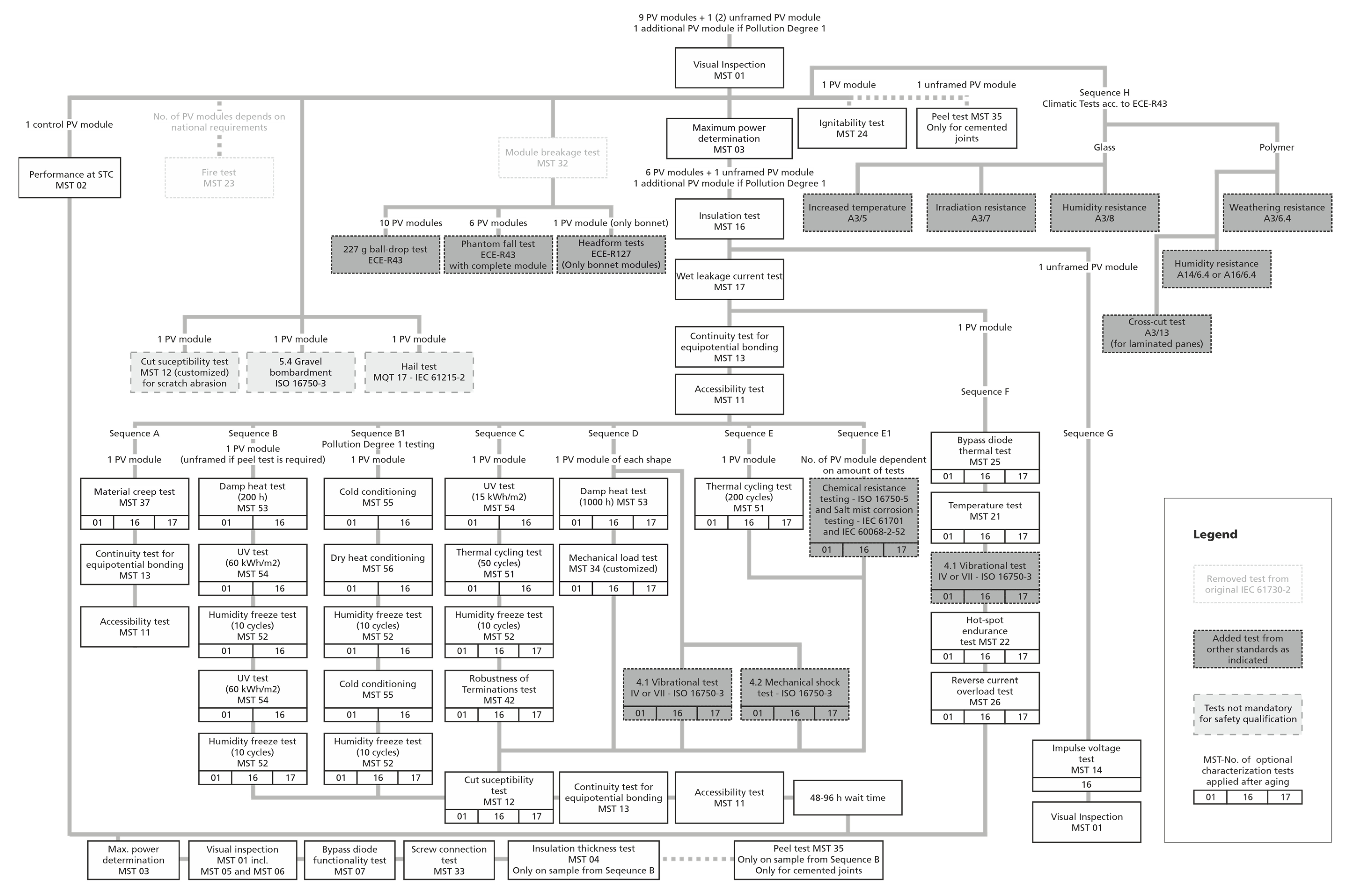
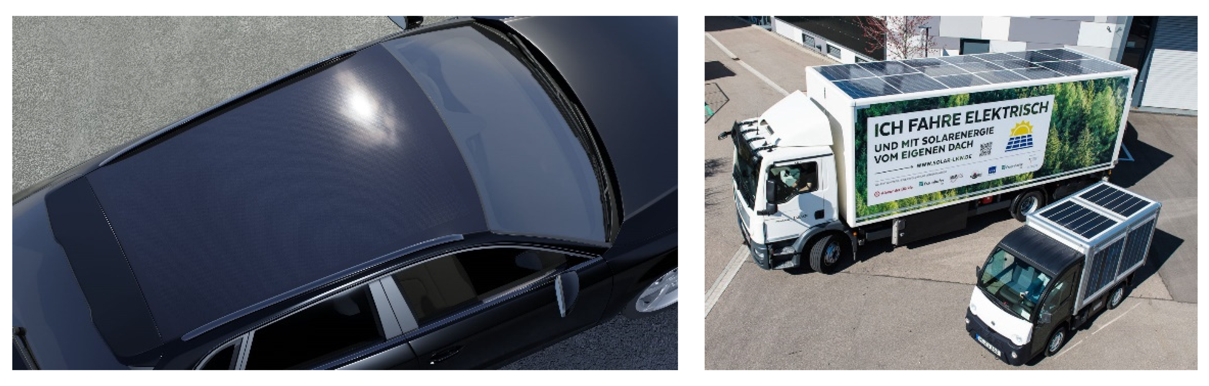
:1. Towards Homologation of Vehicle-Integrated Photovoltaics

| Standard | Scope |
|---|---|
| ISO 16750 (−1, −2, −3, −4, −5) [18] | Road vehicles—Environmental conditions and testing for electrical and electronic equipment: Part 1: General Part 2: Electrical loads Part 3: Mechanical loads Part 4: Climatic loads Part 5: Chemical loads |
| ISO 20653 [19] | Road vehicles—Degrees of protection (IP code)—Protection of electrical equipment against foreign objects, water, and access |
| ECE-R10 [20] | Uniform provisions concerning the approval of vehicles with regard to electromagnetic compatibility |
| ECE-R43 [21] | Uniform provisions concerning the approval of safety glazing materials and their installation on vehicles |
| ECE-R95 [22] | Uniform provisions concerning the approval of vehicles with regard to the protection of the occupants in the event of a lateral collision |
| ECE-R100 [23] | Uniform provisions concerning the approval of vehicles with regard to specific requirements for the electric power train |
| ECE-R118 [24] | Uniform technical prescriptions concerning the burning behavior of materials used in the interior construction of certain categories of motor vehicles |
| ECE-R127 [25] | Uniform provisions concerning the approval of motor vehicles with regard to their pedestrian safety performance |
2. Review of Normative References and Regulations
2.1. Comparison of Standards
- General
- Electrical loads
- Fire hazards
- Mechanical loads
- Environmental/climatic loads
- Chemical loads
2.2. General Inspection
2.3. Electrical Protection/Electrical Loads
2.4. Fire Hazards
2.5. Mechanical Loads
2.5.1. Mechanical Robustness and Vibrational Loads
2.5.2. Rupture Safety
2.5.3. Pedestrian Safety
2.5.4. Comparison of Three Different Impact Test Scenarios
2.6. Climatic Loads
2.7. Chemical Loads
3. Conclusions
Author Contributions
Funding
Institutional Review Board Statement
Informed Consent Statement
Data Availability Statement
Acknowledgments
Conflicts of Interest
Appendix A
References
- Kutter, C.; Basler, F.; Neuhaus, D.H.; Heinrich, M.; Markert, J.; Alanis, L.E. Integrated Lightweight, Glass-Free PV Module Technology for Box Bodies of Commercial Trucks. In Proceedings of the 37th European Photovoltaic Solar Energy Conference and Exhibition, WIP Renewable Energies, Lisbon, Portugal, 7–11 September 2020; pp. 1711–1718. [Google Scholar] [CrossRef]
- Heinrich, M.; Kutter, C.; Basler, F.; Mittag, M.; Alanis, E.; Eberlein, D.; Schmid, A.; Reise, C.; Kroyer, T.; Neuhaus, H.; et al. Potential and Challenges of Vehicle Integrated Photovoltaics for Passenger Cars. In Proceedings of the 37th European Photovoltaic Solar Energy Conference and Exhibition, WIP Renewable Energies, Lisbon, Portugal, 7–11 September 2020. [Google Scholar]
- Carr, A.J.; Burgers, A.R.; van den Tillaart, E.; Kohler, T.; Newman, B.K. Quantifying the benefit of VIPV. Sol. Mobil. Forum Woensdag 16 Sept. 2020, 2020, 1. [Google Scholar]
- Carr, A.J.; van den Tillaart, E.; Burgers, A.R.; Köhler, T.; Newman, B.K. Vehicle integrated photovoltaics: Evaluation of the energy yield potential through monitoring and modelling. In Proceedings of the 37th European Photovoltaic Solar Energy Conference and Exhibition, WIP Renewable Energies, Lisbon, Portugal, 7–11 September 2020. [Google Scholar]
- Yamaguchi, M.; Masuda, T.; Araki, K.; Sato, D.; Lee, K.-H.; Kojima, N.; Takamoto, T.; Okumura, K.; Satou, A.; Yamada, K.; et al. Development of high-efficiency and low-cost solar cells for PV-powered vehicles application. Prog. Photovolt: Res. Appl. 2020, 29, 684–693. [Google Scholar] [CrossRef]
- ITRPV. International Technology Roadmap for Photovoltaic (ITRPV): 2020 Results, April 2021; No. 12, Frankfurt, 2021. Available online: https://itrpv.vdma.org/download (accessed on 10 May 2021).
- Hyundai Motor Company. 2020 SONATA Hybrid—Solar Roof Panel. Available online: https://www.hyundaiusa.com/us/en/vehicles/sonata-hybrid (accessed on 3 March 2021).
- Toyota. Prius Plugin. Available online: https://www.toyota.de/automobile/prius-plugin/ (accessed on 3 February 2021).
- Baliozian, P.; Klasen, N.; Wöhrle, N.; Kutter, C.; Stolzenburg, H.; Münzer, A.; Saint-Cast, P.; Mittag, M.; Lohmüller, E.; Fellmeth, T.; et al. PERC-based shingled solar cells and modules at Fraunhofer ISE. Photovolt. Int. 2019, 43, 129–145. [Google Scholar]
- Sono Motors GmbH. Sion. Available online: https://sonomotors.com/de/sion/ (accessed on 3 February 2021).
- Lightyear. Design—Solar Roof and Hood. Available online: https://lightyear.one/lightyear-one/ (accessed on 3 March 2021).
- International Electrotechnical Commission. IEC 61730: Photovoltaic (PV) Module Safety Qualification—Part. 1, Edition 2.0; International Electrotechnical Commission: Geneva, Switzerland, 2016; IEC 61730-1. [Google Scholar]
- International Electrotechnical Commission. IEC 61730: Photovoltaic (PV) Module Safety Qualification—Part. 2, Edition 2.0; International Electrotechnical Commission: Geneva, Switzerland, 2016; IEC 61730-2. [Google Scholar]
- International Electrotechnical Commission. IEC 61215: Terrestrial Photovoltaic (PV) Modules: Design Qualification and Type Approval—Part. 1: Test. Requirements, Edition 2.0; International Electrotechnical Commission: Geneva, Switzerland, 2021; IEC 61215-1:2021. [Google Scholar]
- International Electrotechnical Commission. IEC 61215: Terrestrial Photovoltaic (PV) Modules: Design Qualification and Type Approval—Part. 2: Test. Procedures, Edition 2.0; International Electrotechnical Commission: Geneva, Switzerland, 2021; IEC 61215-2:2021. [Google Scholar]
- Regulation (EC) No 661/2009 of the European Parliament and of the Council of 13 July 2009. In Concerning Type-Approval Requirements for the General Safety of Motor Vehicles, Their Trailers and Systems, Components and Separate Technical Units Intended Therefor; European Parliament and Council: Brussels, Belgium, 2009.
- Regulation (EU) 2018/858 of the European Parliament and of the Council of 30 May 2018 on the approval and market surveillance of motor vehicles and their trailers, and of systems, components and separate technical units intended for such vehicles, amending Regulations (EC) No 715/2007 and (EC) No 595/2009 and repealing Directive 2007/46/EC. Off. J. Eur. Union 2018, OJ L 151, 1–218.
- International Organization for Standardization. ISO 16750 2010-04: Road Vehicles—Environmental Conditions and Testing for Electrical and Electronic Equipment—Part. 1-5, 3rd ed.; ISO: Geneva, Switzerland, 2018. [Google Scholar]
- International Organization for Standardization. ISO 20653—Road Vehicles—Degrees of Protection (IP Code)—Protection of Electrical Equipment Against Foreign Objects, Water and Access, 2nd ed.; ISO: Geneva, Switzerland, 2013. [Google Scholar]
- Regulation No 10 of the Economic Commission for Europe of the United Nations (UN/ECE)—Uniform Provisions Concerning the Approval of Vehicles with Regard to Electromagnetic Compatibility: UNECE R10; Economic Commission for Europe of the United Nations: Geneva, Switzerland, 2012.
- Regulation No 43 of the Economic Commission for Europe of the United Nations (UN/ECE)—Uniform Provisions Concerning the Approval of Safety Glazing Materials and Their Installation on Vehicles: UNECE R43; Economic Commission for Europe of the United Nations: Geneva, Switzerland, 2009.
- Publications Office of the European Union. Regulation No 95 of the Economic Commission for Europe of the United Nations (UNECE)—Uniform Provisions Concerning the Approval of Vehicles with Regard to the Protection of the Occupants in the Event of a Lateral Collision [2015/1093]: UNECE R95; Economic Commission for Europe of the United Nations: Geneva, Switzerland, 2014. [Google Scholar]
- Regulation No 100 of the Economic Commission for Europe of the United Nations (UNECE)—Uniform Provisions Concerning the Approval of Vehicles with Regard to Specific Requirements for the Electric Power Train [2015/505]: UNECE R100; Economic Commission for Europe of the United Nations: Geneva, Switzerland, 2014.
- Regulation No 118 of the Economic Commission for Europe of the United Nations (UN/ECE)—Uniform Technical Prescriptions Concerning the Burning Behaviour of Materials used in the Interior Construction of Certain Categories of Motor Vehicles: UNECE R118; Economic Commission for Europe of the United Nations: Geneva, Switzerland, 2005.
- Addendum 126: Regulation No. 127—Uniform Provisions Concerning the Approval of Motor Vehicles with Regard to Their Pedestrian Safety Performance; United Nations: Geneva, Switzerland, 2012.
- Directive 2011/65/EU on the restriction of the use of certain hazardous substances in electrical and electronic equipment. Off. J. Eur. Union 2011, OJ L 174, 88–110.
- International Electrotechnical Commission. IEC 61140: Protection Against Electric Shock—Common Aspects for Installation and Equipment, Edition 4.0; International Electrotechnical Commission: Geneva, Switzerland, 2016; IEC 61140:2016. [Google Scholar]
- International Electrotechnical Commission. IEC 60112: Method for the Determination of the Proof and the Comparative Tracking Indices of Solid Insulating Materials, Edition 5.0; International Electrotechnical Commission: Geneva, Switzerland, 2020; IEC 60112:2020. [Google Scholar]
- International Electrotechnical Commission. IEC 60050-212: International Electrotechnical Vocabulary (IEV)—Part. 212: Electrical Insulating Solids, Liquids and Gases, Edition 2.0; International Electrotechnical Commission: Geneva, Switzerland, 2010; IEC 60050-212. [Google Scholar]
- International Electrotechnical Commission. IEC 60695-11-10: Fire Hazard Testing—Part. 11-10: Test. Flames—50 W Horizontal and Vertical Flame Test Methods, Edition 2.0; International Electrotechnical Commission: Geneva, Switzerland, 2013; IEC 60695-11-10:2013. [Google Scholar]
- International Electrotechnical Commission. IEC 61701: Photovoltaic (PV) Modules—Salt Mist Corrosion Testing, Edition 3.0; International Electrotechnical Commission: Geneva, Switzerland, 2020; IEC 61701:2020. [Google Scholar]
- International Electrotechnical Commission. IEC 60068-2-52: Environmental Testing—Part. 2-52: Tests—Test. Kb: Salt Mist, Cyclic (Sodium Chloride Solution), Edition 3.0; International Electrotechnical Commission: Geneva, Switzerland, 2017; IEC 60068-2-52. [Google Scholar]
| IEC 61730-2 Module Breakage Test | ECE-R43 Phantom Fall Test | ECE-R127 Adult Headform Test | |
|---|---|---|---|
| Impactor Weight | 45 kg | 10 kg | 4.5 kg |
| Test Setup | Pendulum l ≥ 1525 mm | Free fall | Free fall |
| Test Specification | Drop height = 300 mm | Drop height = 3 m (when head injury is expected) | Impact velocity = 9.7 m/s |
| Sample Specifications | PV module | Material sample 6 plane samples: 1100 × 500 mm2 (glass) 1170 × 570 mm2 (Polymer) or complete unit | Whole vehicle front (with bonnet) |
| Energy of Impact | 132 J | 294 J | 212 J |
| Pass Criteria | No separation from mounting structure or framing and no breakage or no opening >Ø = 76 mm shall develop and no particles >65 cm2 shall be ejected from the sample. | Rigid and Double Polymer Glazing: Sample shall not be penetrated or break into separated pieces; When head injury is expected: HIC < 1000 | HIC recorded shall not exceed 1000 over two thirds of the combined child and adult headform test areas. The HIC for the remaining areas shall not exceed 1700 for both headforms. |
| Glass: Sample shall not be penetrated or break into separated pieces, breakage of glass allowed |
| IEC 61730-2 | ISO 16750-4 | ||
|---|---|---|---|
| Tests | Conditions | Tests | Conditions |
| MST 51—Temperature Cycle—TC50 or TC200 | −40–85 °C, max. 100 °C/h, min. 10 min dwell time | 5.2 Temperature step test | 5 °C steps from 20 °C -> Tmin -> Tmax (acc. to code letter G) |
| 5.3.1 Temperature Cycling (TC30) | 150 min at Tmin + 410 min at Tmax (acc. to code letter G) | ||
| MST 52—Humidity Freeze | 10 cycles, −40–85 °C, 85% rH | 5.6 Humid heat cyclic test (2 and 3 acc. To code letter H) | 5 cycles, 25–80 °C, max 95% rH |
| MST 53—Damp Heat (DH1000) | 85 °C, 85% rH, 1000 h | 5.7 Damp heat steady state test | 40 °C, 85% rH, 500 h |
| MST 54—UV Preconditioning | 280–320 nm/320–400 nm, 15 kWh/m2 or 60 kWh/m2 | 5.9 Solar radiation | If required, resistance to solar radiation shall be ensured by the choice of a suitable material. |
| MST 55—Cold Conditioning | −40 °C, 48 h | 5.1.1 Low temperature | −40 °C, 24 h |
| MST 56—Dry Hot Conditioning | 105 °C, <50% rH, 200 h | 5.1.2 High temperature | 85 °C, 48 h |
| Recommended Alignments | Motivation |
|---|---|
| 5% power loss allowed during stress tests (acc. To IEC 61215:2021) | Ensure module quality for market acceptance |
| Addition of vibrational tests from ISO 16750-3 | Ensure mechanical stability throughout vehicle operation, e.g., during door slamming or rough road driving |
| Chemical testing from ISO 16750-5 | Ensure module stability against chemical loads |
| Salt mist corrosion testing acc. to IEC 61701 and IEC 60068-2-52 (method 7 + 8) | Ensure environmental stability of modules in winter |
| Separate climatic testing acc. to ECE-R43 | Climatic testing for safety glass |
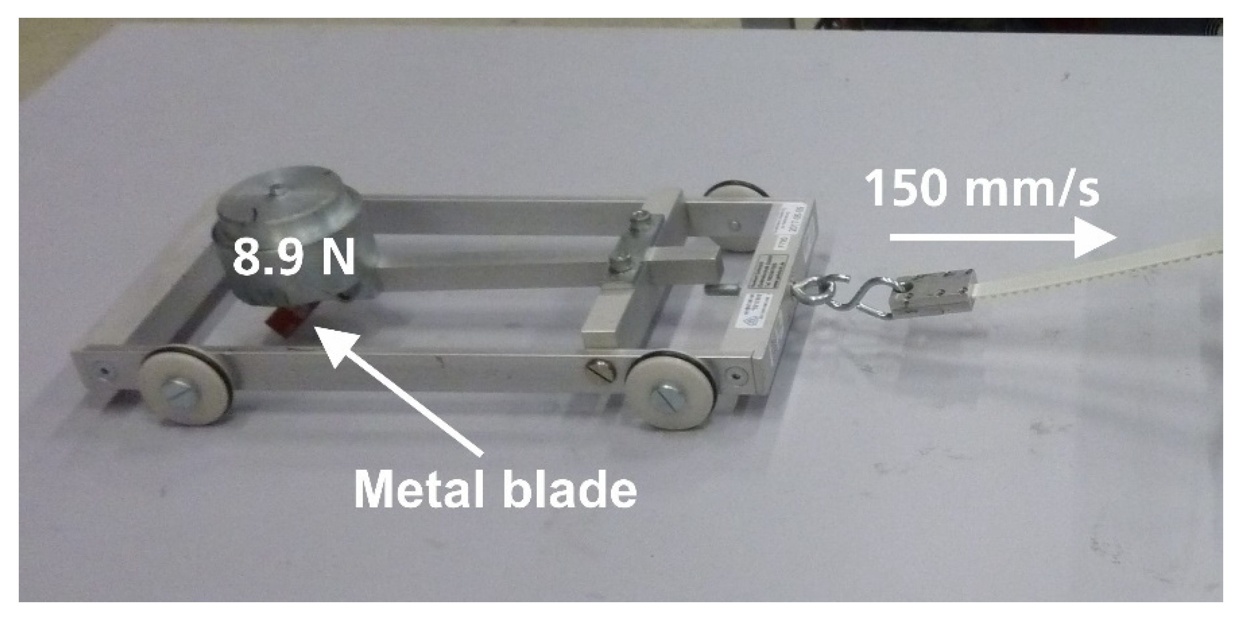
| Definition of tests for surface strength/scratch and abrasion resistance | Important for market acceptance in case of snow removal, shopping cart collision, branch scratching -> enhancement of cut susceptibility test (IEC 61730-2, MST 12), also other than polymer materials shall be tested |
| Gravel bombardment test | Ensure module quality for market acceptance |
| Continuative testing after breakage | Ensure safety of possibly damaged modules during continuative operation |
| Increase in max. T during climatic testing to 95 °C | Reproduce realistic operation scenarios, e.g., broken VIPV module -> possible undetected hot-spot formation |
Publisher’s Note: MDPI stays neutral with regard to jurisdictional claims in published maps and institutional affiliations. |
© 2021 by the authors. Licensee MDPI, Basel, Switzerland. This article is an open access article distributed under the terms and conditions of the Creative Commons Attribution (CC BY) license (https://creativecommons.org/licenses/by/4.0/).
Share and Cite
Markert, J.; Kutter, C.; Newman, B.; Gebhardt, P.; Heinrich, M. Proposal for a Safety Qualification Program for Vehicle-Integrated PV Modules. Sustainability 2021, 13, 13341. https://doi.org/10.3390/su132313341
Markert J, Kutter C, Newman B, Gebhardt P, Heinrich M. Proposal for a Safety Qualification Program for Vehicle-Integrated PV Modules. Sustainability. 2021; 13(23):13341. https://doi.org/10.3390/su132313341
Chicago/Turabian StyleMarkert, Jochen, Christoph Kutter, Bonna Newman, Paul Gebhardt, and Martin Heinrich. 2021. "Proposal for a Safety Qualification Program for Vehicle-Integrated PV Modules" Sustainability 13, no. 23: 13341. https://doi.org/10.3390/su132313341