Article

Modular Green Roofs for the Sustainability of the Built Environment: The Installation Process

by
Natalia Sergeevna Shushunova
1,*,
Elena Anatolyevna Korol
1 and
Nikolai Ivanovich Vatin
2
1
Moscow State University of Civil Engineering, 129337 Moscow, Russia
2
Institute of Civil Engineering, Peter the Great St. Petersburg Polytechnic University, 195251 St. Petersburg, Russia
*
Author to whom correspondence should be addressed.
Sustainability 2021, 13(24), 13749; https://doi.org/10.3390/su132413749
Submission received: 25 September 2021 / Revised: 5 December 2021 / Accepted: 7 December 2021 / Published: 13 December 2021

Abstract

:
The research object is the installation process of modular green roofs with planters placed on the concrete roof’s surface. These roofs effectively reduce rainfall disposal, prolong the lifespan of the roof coating, and enhance urban aesthetic and recreational spaces. Green roofs reduce houses’ gas emissions and increase green spaces in densely built areas. The spatial–technological model was developed for the proposed modular green roof based on network planning, scheduling theory, and graph theory. The sequence and composition of technological processes and operations were established for the installation process. The functional model of installing a modular green roof has been developed. The model makes it possible to optimise the principles of saving labour contribution (working hours) and time.

1. Introduction

Green roofs on buildings have multi-disciplinary benefits such as the improvement of rainfall disposal, the prolonged lifespan of the roof coating, the enhancement of urban aesthetic, and the creation of recreational spaces [1,2]. A quantitative analysis of 1623 English language sources indexed in Scopus from 1981 to 2020 shows that research on green roofs has steadily increased. Approximately 40.9% of the articles focus on regulating services in water, 30.0% on the thermal environment, and 3.5% on air quality [3]. Green roofs showed a surface temperature cooling effect [4,5]. The effects of urban heat islands [6] and global warming have led to an increased greening of cities as a tool for urban heat island mitigation in three main climate types: hot–humid, temperate, and dry [7,8,9,10,11]. Sustainability concerns have necessitated a shift towards sustainable urban water management systems, which could be analysed as multiphysics systems [12]. These systems include wet ponds, rain gardens, and green roofs [13]. Green roofs can contribute certain pollutants to rainfall disposal [14].
According to the 70th edition of Statistical Review of World Energy from British Petroleum in 2021 [15], the top five countries accounted for 59.4% of all CO2 emissions. The largest emitter was China, as its share was 30.7%. The United States, with a share of 13.8%, was in second place; India, with a share of 7.1%, is in third place; Russia, with a share of 4.6%, is in fourth place; and Japan, with a share of 3.2%, is in fifth place. Therefore, it is necessary to establish full-fledged monitoring of this process on the planet.
The absorption of carbon dioxide could be achieved with an increase in green spaces in cities by creating green roofs and green walls on public buildings. Green roofs reduce houses’ gas emissions and increase green spaces in densely built areas [16,17,18,19,20,21]. Another benefit of green roofs is that they offer new job opportunities; the larger the area, the more people are needed to design and maintain the roofing. Buildings with green roofs are more attractive to tenants and buyers, which means they can be rented out and sold at a higher rate [22].
Green roofs can be integrated with photovoltaics, providing additional benefits compared to the conventional green roof. The various challenges hinder the large-scale implementation of photovoltaic–green roofs, including high initial costs, limited experimental data, and lack of awareness about the long-term benefits [23].
There are two possible green roof technological design types: stationary and modular.
On a stationary green roof, the primary layers are the waterproof and anti-root membranes; the protection, filter, and drainage layers; the substrate; and the vegetation. Commercial materials and products available in the market were provided, and innovative materials from recycled sources were analysed [24]. It is possible to use a three-layer concrete slab as a base coat for green roofs. The effectiveness of thermal insulation of a multi-layer, reinforced concrete slab using a layer of concrete with low thermal conductivity and properties of lightweight concrete under the conditions in tropical climates was studied in [25]. The thermal inertia of the extensive green roof in summer conditions was experimentally assessed [26,27,28].
There are no primary layers on the modular green roof in contrast to the stationary green roof. One of the modular green roof types was proposed by the authors E. Korol and N. Shushunova [29,30]. Planters with plants are placed on the concrete roof’s surface [31,32]. Figure 1 shows the principal scheme of the modular green roof.
The main advantages of modular green roof systems over roll-out green roofs surround convenience and speed of the installation process. Green roof modules can be hand-balled into even the most awkward areas. They can be used to retrofit products for placing on existing conventional roofs [29]. Modular green roofs allow easy and quick replacement of plant pots during the entire life cycle of the roof.
However, no standard assessment methods exist to value green roofs, and balance between different services is lacking [3]. There is still a lack of comprehensive calculation of the economic merit of green roofs and walls, including their installation process, which has restricted the decision-making process [33]. Green roof implementation can be constrained by unsound economic assessment [34].
It follows from the above review that multiphysics processes have not been developed to optimise the technological processes of building green roofs. This study aims to create a spatial–technological model for the proposed modular green roof’s installation, based on network planning, scheduling theory, and graph theory.

2. Materials and Methods

The research uses a formalised method for analysis of installing modular green roofs and defines the labour costs of technological processes and operations. The method is based on the principles of saving labour contribution (working hours) and time. Network planning, scheduling theory, and graph theory are used. The formal methods of expert assessment are also included [35].

3. Results and Discussion

The following mathematical model was built to calculate installation time and costs and to rationalise the installation organisation. The model of technological processes of the modular green roof installation consists of a spatial–technological model and a functional model (Figure 2).
The spatial–technological model consists of resource modules, front modules, and work modules. The resource module is the technological process’s minimum technical (labour) resource for performing a working operation (work module) with a volume equal to its shift production. It occupies the necessary working space (front module) for this working operation. These elements make up the organisational and technological modules of individual technological processes of the modular green roof (Figure 2). Organisational modules and technological modules have different physical natures. The model describing all of them is multiphysical.
The installation process was divided into 24 sequential technological operations, listed in Table 1 in the technological sequence of expert assessment [35].
The algorithm for constructing a spatial and technological structural model was divided into the following stages:
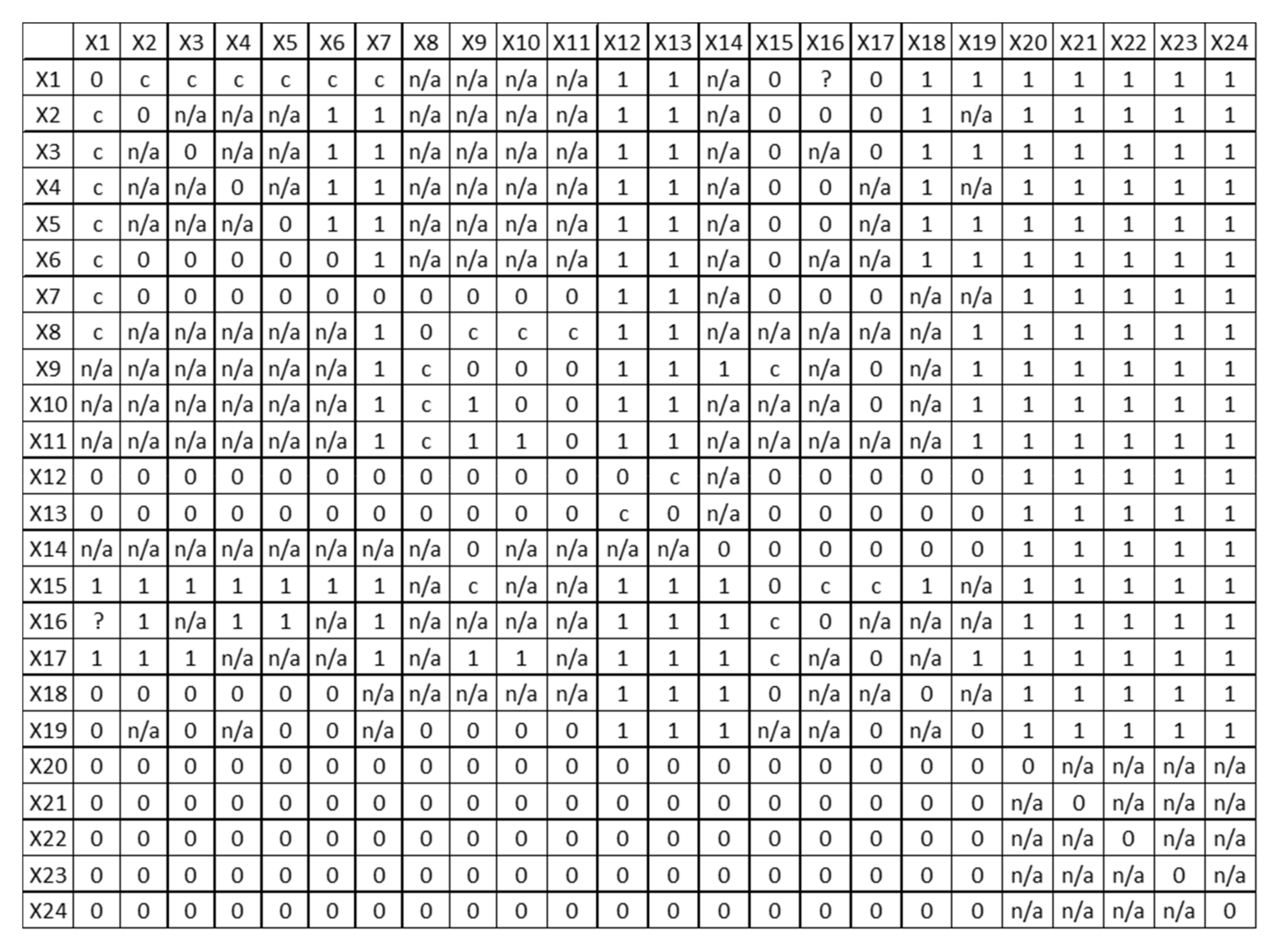
  • Construction of a matrix of technological links of organisational and technological module processes based on the results of an expert assessment of the succession–precedence of technological processes (operations) in paired comparisons.
  • Creation of a graph of the technological sequence based on the matrix data (excluding compound operations).
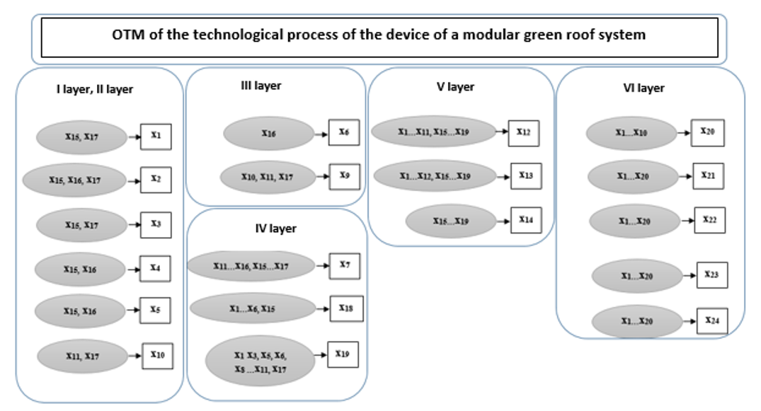
  • Fragmentation of the graph into specific layers (finding and filtering out paths resulting from the transitivity property).
  • Creation of the final graph of the spatial and technological structure of the organisational and technological module.
First, the technological ordering of the processes and construction of a matrix of technological links of organisational and technological module processes was carried out based on an expert assessment of the succession–precedence of technological processes (operations) in paired comparisons. It is required to find a sequence Y i that is a permutation of the sequence X i such that the fact that Y i < < Y j implies that i < j . The “<< “ sign was introduced to denote the order in the technological sequence of processes, namely when the sequence X i precedes the sequence X j .
The conventions for the matrix X i j elements were introduced to do this ordering. The conventions are as follows:
(1)
X i j = 1   if   X i < < X j
(2)
X i j = 0   if   X j < < X i
(3)
X i j = n / a if condition 1 and condition 2 are not met.
(4)
X i j = c if one of the elements is an integral part of the other.
(5)
X i j = ? if the relationship between a simple and a composite technological operation cannot be determined.
Figure 3 represents the resulting matrix X in the form of a technological sequence. The matrix is divided into layers so that all the elements of this layer do not have predecessor works in this, and previous layers and the elements of the first layer do not have predecessor works. The elements of the last one do not have successor works.
The following algorithm was introduced for this division:
  • All the rows of the matrix that satisfy the condition: i j ,   X i j 0 are found.
  • The elements X i j 0 are replaced in the first layer of the row in which they are found.
  • Elements X i j belonging to the next layer are found. It is necessary to find such rows X i that i j ,   X i j = 0 implies that the row X i is contained in the set of layers from the first layer to the layer under consideration.
This algorithm for fragmentation of the graph into layers is finished when all rows X i that do not contain ones are found.
Figure 4 shows the results as a graph of the technological structure of the organisational and technological module with fragmentation into layers so that the processes (operations) are technologically independent. Hence, the processes (operations) can be performed in parallel.
The constructed graph indicates technological operations in the form of elements X i j of the matrix. The arrows show the technological connections between operations. Based on the constructed graph, the following can be established:
(1)
Technological operation X 15 is composite.
(2)
It includes operations X 9 ,   X 16 ,   X 17   , which may be present in any of 1–3 layers.
(3)
Technological operation X 14 is not composite. It may be executed in parallel with operation X 12 .
(4)
Based on the results of constructing the graph, the cycles are eliminated.
After constructing the graph, a new list of technological processes and operations of organisational and technological modules for the green roof was compiled, indicating the workplaces of the work. The technological operations are numbered in this list based on their technological sequence. In the graph, simple technological operations that are not a part of others begin with the capital letter “Y” and compound operations with the lowercase “y”. As a result of these operations’ spatial and technological ordering based on network planning methods, a model (graph) of the “top-work” type was formed (Figure 5).
The “= =“ sign was introduced to denote the relationship of spatial equivalence. The rule of the denotation is as follows: if Y i , Y j Y i   &   k i = k j , then Y i =   = Y j . This relation is reflected in the graph of the spatial structure of the technological process. Connections of spatial equivalence were established in the places where it is possible to perform them in a specific subspace. There,
  • k 1 
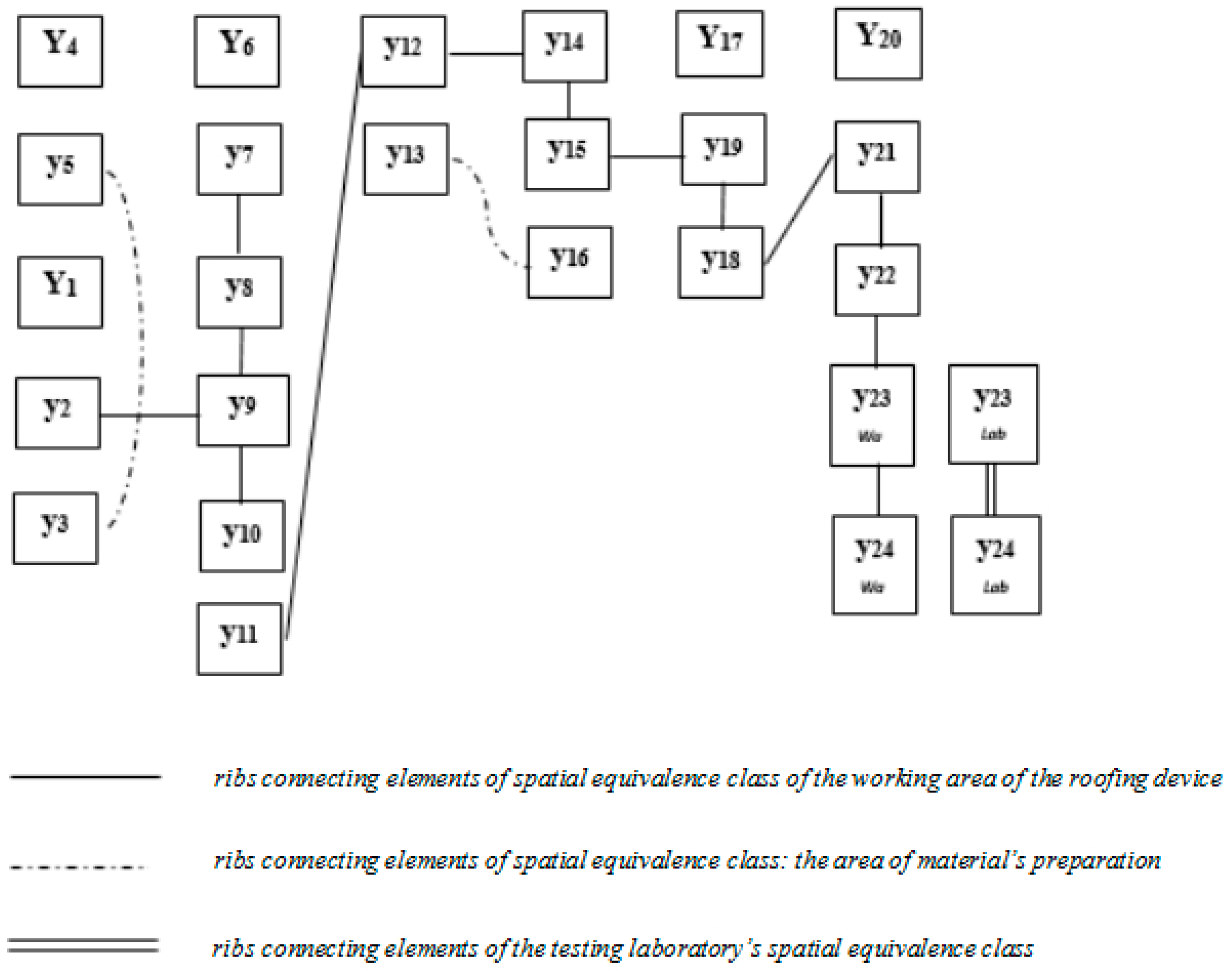
is the main subspace, i.e., the class of spatial equivalence of the working area of the roofing device (connections between operations performed in the working area);
  • k 2 is the class of spatial equivalence: site of acceptance and preparation of materials (serving subspace); and
  • k 3 is the spatial equivalence class of the testing laboratory (serving subspace).
Then, a graph of resource equivalence of a roofing device with modular landscaping is built (Figure 6), and the performers of technological processes and operations are assigned the corresponding numbers—resource equivalence classes (l):
  • l 1 is the labour resource equivalence of the class: master in the amount of one person;
  • l 2 is the labour resource equivalence of the class: rigger of the second category in the amount of two persons, driver of the sixth category in the amount of one person;
  • l 3 is the resource equivalence class: ancillary worker of the second category in the amount of one person;
  • l 4 is the resource equivalence class: roofer of the second category in the amount of two persons, roofer of the third category in the amount of one person; and
  • l 5 is the resource equivalence class: laboratory assistant in the amount of one person.
Classes of spatial equivalence k and classes of resource equivalence l are introduced to assess technological operations that can be performed in parallel (up to the front module).
The organisational and technological module was developed after the spatial and technological structure were constructed and the technological and spatial ordering of technological processes were formed.
In the functional model, for each technological process (technological operation), the value of its execution time t i j k l is introduced, where:
  • i 
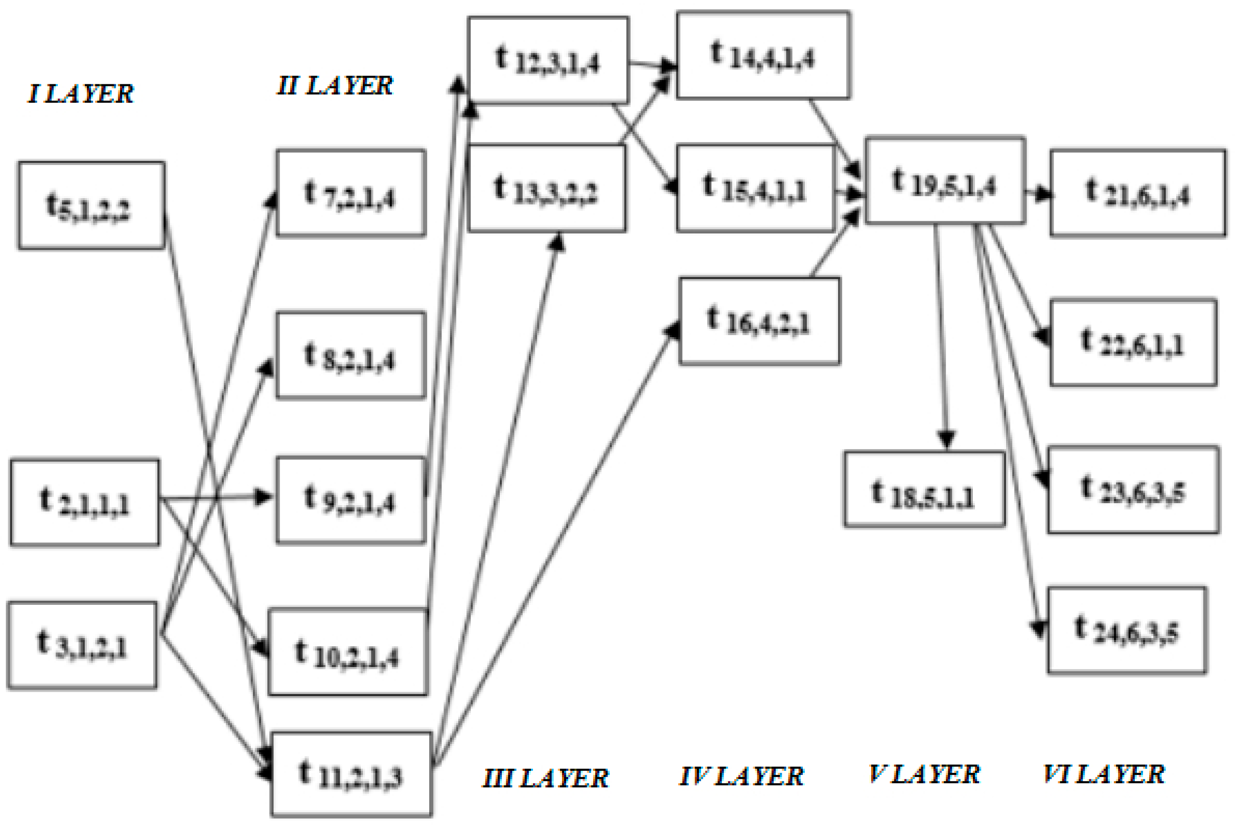
is the index of the sequence element (operation number), i = 1 ,   2 ,   ...   24 ;
  • j is the number of the layer in which the operation is located, j = 1 ,   2 ,   ...   6 ;
  • k is the number of the main or serving subspace, k = 1 ,   2 ,   3 ; and
  • l is the number (class) of the labour resource, i = 1 ,   2 ,   ...   5 .
In this case, the value t i j k l can be unambiguously replaced by the value t 1 as t i j k l = t 1 (Figure 7).
With the formed structural and functional model, the total duration of the operations of the main subspace of the organisational and technological module is found according to the formula:
T O T M = j = 1 7 f ( t i n , j , k , l n ,   f ( t i n 1 , j , k , l n 1 ,   f ( t i 2 , j , k , l 2 ) ) )
where n for each j is the number of elements in the layer,
( t i n , j , k , l n ,   t i n , j , k , l n ) = t i n , j , k , l n + t i n , j , k , l n , if   l 1 = l 2 ( sequential   work   of   one   resource ) max   ( t i n , j , k , l n . t i n , j , k , l n ) , if   l 1 l 2   ( parallel   work   on   two   resources )
The duration of work in the main subspace is decisive for the remaining subspaces and adjacent processes. Therefore, work operations in the serving subspaces can begin at earlier times than in the main subspace.
Thus, creating the structural–functional model makes it possible to determine the main indicators of the organisational efficiency of installing the modular green roof.

4. Conclusions

The research object is the installation process of modular green roofs with planters placed on the concrete roof’s surface. These roofs effectively reduce rainfall disposal, increase the prolonged lifespan of the roof coating, and enhance urban aesthetic and recreational spaces. Green roofs reduce houses’ gas emissions and increase green spaces in densely built areas.
One of the modular green roof types was proposed by the authors E. Korol and N. Shushunova [29,30]. However, no standard assessment methods exist to value green roofs, and balance between different services is lacking [3]. There is still a lack of comprehensive calculation of the economic merit of green roofs and walls, including their installation process, which has restricted the decision-making process [33]. Green roof implementation can be constrained by unsound economic assessment [34].
The spatial–technological model was developed for the proposed modular green roof based on network planning, scheduling theory, and graph theory. Analysing the model led to the following conclusions:
(1)
The sequence and composition of technological processes and operations was established for installing the modular green roof.
(2)
The spatial and technological structure model has been built as a result of the formation of technological and spatial ordering of technological processes.
(3)
The functional model of installing a modular green roof has been developed. The model makes it possible to optimise on the principles of saving labour contribution (working hours) and time.

Author Contributions

Conceptualisation, N.S.S., E.A.K., and N.I.V.; methodology, N.S.S. and E.A.K.; validation, N.S.S. and E.A.K.; formal analysis, N.S.S.; investigation, N.S.S. and E.A.K..; resources, N.S.S., E.A.K., and N.I.V.; data curation, N.S.S. and E.A.K.; writing—original draft preparation, N.S.S. and E.A.K.; writing—review and editing, N.I.V.; supervision, E.A.K.; project administration, E.A.K.; funding acquisition, N.I.V. All authors have read and agreed to the published version of the manuscript.

Funding

The research is partially funded by the Ministry of Science and Higher Education of the Russian Federation as part of the World-class Research Center program: Advanced Digital Technologies (contract No. 075-15-2020-934 dated 17 November 2020).

Institutional Review Board Statement

Not applicable.

Informed Consent Statement

Not applicable.

Data Availability Statement

The data presented in this study are available on request from the corresponding author.

Conflicts of Interest

The authors declare no conflict of interest.

References

  1. Bevilacqua, P. The effectiveness of green roofs in reducing building energy consumptions across different climates. A summary of literature results. Renew. Sustain. Energy Rev. 2021, 151, 111523. [Google Scholar] [CrossRef]
  2. Hanumesh, M.; Claverie, R.; Séré, G. A roof of greenery, but a sky of unexplored relations—Meta-analysis of factors and properties that affect green roof hydrological and thermal performances. Sustainability 2021, 13, 10017. [Google Scholar] [CrossRef]
  3. Liu, H.; Kong, F.; Yin, H.; Middel, A.; Zheng, X.; Huang, J.; Xu, H.; Wang, D.; Wen, Z. Impacts of green roofs on water, temperature, and air quality: A bibliometric review. Build. Environ. 2021, 196, 107794. [Google Scholar] [CrossRef]
  4. Knight, T.; Price, S.; Bowler, D.; Hookway, A.; King, S.; Konno, K.; Richter, R.L. How effective is ‘greening’ of urban areas in reducing human exposure to ground-level ozone concentrations, UV exposure and the ‘urban heat island effect’? An updated systematic review. Environ. Evid. 2021, 10, 1–38. [Google Scholar] [CrossRef]
  5. Priya, U.K.; Senthil, R. A review of the impact of the green landscape interventions on the urban microclimate of tropical areas. Build. Environ. 2021, 205, 108190. [Google Scholar] [CrossRef]
  6. Gorshkov, A.S.; Vatin, N.I.; Rymkevich, P.P. Climate change and the thermal island effect in the million-plus city. Constr. Unique Build. Struct. 2020, 89, 8902. [Google Scholar] [CrossRef]
  7. Parsaee, M.; Joybari, M.M.; Mirzaei, P.A.; Haghighat, F. Urban heat island, urban climate maps and urban development policies and action plans. Environ. Technol. Innov. 2019, 14, 100341. [Google Scholar] [CrossRef]
  8. Jamei, E.; Chau, H.W.; Seyedmahmoudian, M.; Stojcevski, A. Review on the cooling potential of green roofs in different climates. Sci. Total Environ. 2021, 791, 148407. [Google Scholar] [CrossRef]
  9. Liu, Z.; Cheng, W.; Jim, C.Y.; Morakinyo, T.E.; Shi, Y.; Ng, E. Heat mitigation benefits of urban green and blue infrastructures: A systematic review of modeling techniques, validation and scenario simulation in ENVI-met V4. Build. Environ. 2021, 200, 107939. [Google Scholar] [CrossRef]
  10. Wong, N.H.; Tan, C.L.; Kolokotsa, D.D.; Takebayashi, H. Greenery as a mitigation and adaptation strategy to urban heat. Nat. Rev. Earth Environ. 2021, 2, 166–181. [Google Scholar] [CrossRef]
  11. Krayenhoff, E.S.; Broadbent, A.M.; Zhao, L.; Georgescu, M.; Middel, A.; Voogt, J.A.; Martilli, A.; Sailor, D.J.; Erell, E. Cooling hot cities: A systematic and critical review of the numerical modelling literature. Environ. Res. Lett. 2021, 16, 053007. [Google Scholar] [CrossRef]
  12. Liu, T.; Lawluvy, Y.; Shi, Y.; Yap, P.-S. Low Impact Development (LID) Practices: A Review on Recent Developments, Challenges and Prospects. Water. Air Soil Pollut. 2021, 232, 1–36. [Google Scholar] [CrossRef]
  13. Adem Esmail, B.; Suleiman, L. Analyzing Evidence of Sustainable Urban Water Management Systems: A Review through the Lenses of Sociotechnical Transitions. Sustainability 2020, 12, 4481. [Google Scholar] [CrossRef]
  14. Hachoumi, I.; Pucher, B.; De Vito-Francesco, E.; Prenner, F.; Ertl, T.; Langergraber, G.; Fürhacker, M.; Allabashi, R. Impact of Green Roofs and Vertical Greenery Systems on Surface Runoff Quality. Water 2021, 13, 2609. [Google Scholar] [CrossRef]
  15. Statistical Review of World Energy 2021 by British Petroleum. Available online: https://www.bp.com/content/dam/bp/business-sites/en/global/corporate/pdfs/energy-economics/statistical-review/bp-stats-review-2021-full-report.pdf (accessed on 29 October 2021).
  16. Rafael, S.; Correia, L.P.; Ascenso, A.; Augusto, B.; Lopes, D.; Miranda, A.I. Are green roofs the path to clean air and low carbon cities? Sci. Total Environ. 2021, 798, 149313. [Google Scholar] [CrossRef]
  17. Seyedabadi, M.R.; Eicker, U.; Karimi, S. Plant selection for green roofs and their impact on carbon sequestration and the building carbon footprint. Environ. Chall. 2021, 4, 100119. [Google Scholar] [CrossRef]
  18. Nadeeshani, M.; Ramachandra, T.; Gunatilake, S.; Zainudeen, N. Carbon Footprint of Green Roofing: A Case Study from Sri Lankan Construction Industry. Sustainability 2021, 13, 6745. [Google Scholar] [CrossRef]
  19. Trovato, M.R.; Nocera, F.; Giuffrida, S. Life-Cycle Assessment and Monetary Measurements for the Carbon Footprint Reduction of Public Buildings. Sustainability 2020, 12, 3460. [Google Scholar] [CrossRef] [Green Version]
  20. Joshi, M.Y.; Teller, J. Urban Integration of Green Roofs: Current Challenges and Perspectives. Sustainability 2021, 13, 12378. [Google Scholar] [CrossRef]
  21. Hirano, Y.; Ihara, T.; Gomi, K.; Fujita, T. Simulation-Based Evaluation of the Effect of Green Roofs in Office Building Districts on Mitigating the Urban Heat Island Effect and Reducing CO2 Emissions. Sustainability 2019, 11, 2055. [Google Scholar] [CrossRef] [Green Version]
  22. Balaban, O.; Puppim de Oliveira, J.A. Sustainable buildings for healthier cities: Assessing the co-benefits of green buildings in Japan. J. Clean. Prod. 2017, 163, S68–S78. [Google Scholar] [CrossRef]
  23. Shafique, M.; Luo, X.; Zuo, J. Photovoltaic-green roofs: A review of benefits, limitations, and trends. Sol. Energy 2020, 202, 485–497. [Google Scholar] [CrossRef]
  24. Cascone, S. Green roof design: State of the art on technology and materials. Sustainability 2019, 11, 3020. [Google Scholar] [CrossRef] [Green Version]
  25. Halwatura, R.U.; Jayasinghe, M.T.R. Thermal performance of insulated roof slabs in tropical climates. Energy Build. 2008, 40, 1153–1160. [Google Scholar] [CrossRef]
  26. Bevilacqua, P.; Mazzeo, D.; Arcuri, N. Thermal inertia assessment of an experimental extensive green roof in summer conditions. Build. Environ. 2018, 131, 264–276. [Google Scholar] [CrossRef]
  27. Abdo, P.; Huynh, B.P.; Irga, P.J.; Torpy, F.R. Evaluation of air flow through an active green wall biofilter. Urban For. Urban Green. 2019, 41, 75–84. [Google Scholar] [CrossRef]
  28. Bevilacqua, P.; Mazzeo, D.; Bruno, R.; Arcuri, N. Surface temperature analysis of an extensive green roof for the mitigation of urban heat island in southern mediterranean climate. Energy Build. 2017, 150, 318–327. [Google Scholar] [CrossRef]
  29. Korol, E.; Shushunova, N. Benefits of a Modular Green Roof Technology. Procedia Eng. 2016, 161, 1820–1826. [Google Scholar] [CrossRef] [Green Version]
  30. Korol, O.; Shushunova, N.; Lopatkin, D.; Zanin, A.; Shushunova, T. Application of High-tech Solutions in Ecodevelopment. MATEC Web Conf. 2018, 251, 06002. [Google Scholar] [CrossRef]
  31. Korol, E.; Shushunova, N. Green Roofs: Standardization and Quality Control of Processes in Green Construction. In Proceedings of the MATEC Web of Conferences, Taichung, Taiwan, 28 October–1 November 2017; Volume 106. [Google Scholar]
  32. Korol, E.; Shushunova, N. Research and Development for the International Standardization of Green Roof Systems. Procedia Eng. 2016, 153, 287–291. [Google Scholar] [CrossRef] [Green Version]
  33. Teotónio, I.; Silva, C.M.; Cruz, C.O. Economics of green roofs and green walls: A literature review. Sustain. Cities Soc. 2021, 69, 102781. [Google Scholar] [CrossRef]
  34. Zhang, G.; He, B.-J. Towards green roof implementation: Drivers, motivations, barriers and recommendations. Urban For. Urban Green. 2021, 58, 126992. [Google Scholar] [CrossRef]
  35. Korol, O.A. Development of the methodology of calendar planning in the system of organizational and technological preparation of capital repair of multi-apartment residential houses. J. Phys. Conf. Ser. 2019, 1425, 012086. [Google Scholar] [CrossRef] [Green Version]
Figure 1. The principal scheme of the modular green roof proposed by the authors [31,32].
Sustainability 13 13749 g001
Figure 2. The spatial–technological model and organisational and technological module (OTM).
Sustainability 13 13749 g002
Figure 3. The matrix of technological links of individual technological processes (operations) of the device of the modular green roof.
Sustainability 13 13749 g003
Figure 4. The graph of the technological structure of the organisational and technological module (OTM) of the technological process of the device of the modular green roof.
Sustainability 13 13749 g004
Figure 5. The graph of the spatial structure of the organisational and technological modules. Wa—working area; Lab—testing laboratory.
Sustainability 13 13749 g005
Figure 6. The graph of the distribution of labour resources of the organisational and technological module of the technological process of the device of a modular roof.
Sustainability 13 13749 g006
Figure 7. The graph of the functional model of the organisational and technological module.
Sustainability 13 13749 g007
Table 1. The list of technological processes and operations of the organisational and technological module of the device of the modular green roof.
The Name of the Technological Process (Technological Operation)Workers (Profession and Persons’ Number)Designation of the Process (Operation) in the Original ListRedesignation of the Process (Operation) in the Technological Sequence
Preparation of the baseRoofers of the 2nd category in the amount of two persons, roofer of the 3rd category in one person x 1 y 6
Marking the covering for laying out the supports (levelling)Roofers of the 2nd category in the amount of two persons, roofer of the 3rd category in one person x 2 y 7
Layout and gluing of supportsRoofers of the 2nd category in two persons, roofer of the 3rd category in one person x 3 y 8
Support tilt angle adjustmentRoofers of the 2nd category in two persons, roofer of the 3rd category in one person x 4 y 9
Fastening the clipsRoofers of the 2nd category in two persons, roofer of the 3rd category in one person x 5 y 10
Laying and fixing the grating on the supportsRoofers of the 2nd category in two persons, roofer of the 3rd category in one person x 6 y 12
Installation and connection of a group of modules in the amount of 4 pcs. fixed to the gratingsRoofers of the 2nd category in two persons, roofer of the 3rd category in one person x 7 y 14
Preparation and transportation of the materialsRiggers of the 2nd category in two persons, driver of the 4th category in one person, driver of the 6th category in one person, ancillary worker of the 2nd category in one person x 8 y 4
Supply of concrete mix solution in boxes by truck craneRiggers of the 2nd category in two persons, driver of the 4th category in one person x 9 y 13
Transportation of materials (goods) by hand cartsAncillary worker of the 2nd category in one person x 10 y 14
Feeding materials to the roof by craneRiggers of the 2nd category in two persons, driver of the 6th category in one person x 11 y 5
Installation of plantersRoofers of the 2nd category in two persons, ancillary worker of the 1st category in one person x 12 y 17
Filling a group of modules with soil and planting materialRoofers of the 2nd category in two persons, ancillary worker of the 1st category in one person x 13 y 19
Operational control of the technological processMaster x 14 y 18
Incoming inspection of materialsMaster x 15 y 1
Verification of compliance with the project arrangement of roof elementsMaster x 16 y 2
Checking the conformity of the project of the incoming materialsMaster x 17 y 3
Quality of preparation of the coating baseMaster x 18 y 15
Control of the technical condition of technological equipmentMaster x 19 y 16
Quality control of finished joints of structural elementsLaboratory assistant, roofer of the 3rd category, master x 20 y 20
Visual controlRoofer of the 3rd category x 21 y 21
Control of geometric parameters of roof elementsMaster x 22 y 22
Non-destructive testing methodsLaboratory assistant x 23 y 23
Testing of roof structures and materialsLaboratory assistant x 24 y 24
Publisher’s Note: MDPI stays neutral with regard to jurisdictional claims in published maps and institutional affiliations.

