Article

The High-Performance Dissipating Frame (HPDF) System for the Seismic Strengthening of RC Existing Buildings

School of Engineering, University of Basilicata, vial dell’Ateneo Lucano, 85100 Potenza, Italy
*
Author to whom correspondence should be addressed.
Sustainability 2021, 13(4), 1864; https://doi.org/10.3390/su13041864
Submission received: 27 December 2020 / Revised: 30 January 2021 / Accepted: 8 February 2021 / Published: 9 February 2021

Abstract

:
In Italy as well as in other earthquake-prone countries, the large number of existing buildings requiring seismic retrofitting calls for sustainable solutions able to reduce both costs and downtime. To this purpose, in this paper, the High-Performance Dissipating Frame system (HPDF), a new strengthening solution for the seismic rehabilitation of existing buildings, is presented. HPDF is based on external precast reinforced concrete (RC) frames rigidly connected to the existing structures and equipped with shear damper devices in order to provide high dissipation capacity. The proposed solution permits: (i) to increase sustainability through works made up from the outside without removing/demolishing infills/other non-structural components, (ii) rapid execution by adopting precast resisting members mutually restrained with steel connections, and (iii) effectiveness due to shear damper devices able to dissipate a large amount of shaking energy. In the paper, a displacement-based design procedure is proposed and applied to a numerical example.

1. Introduction

According to the ISTAT census [1] of the population and houses, the Italian residential building stock includes over 12 million buildings, mostly with masonry structures (more than 7 million) and 3.7 million with reinforced concrete (RC) structures. Although masonry buildings are double the RC ones, there are many more people living in the latter since they are often made up of large multistorey apartment buildings. In addition, large public buildings like schools and hospitals often have RC structures. It means that losses related to damage or collapse of these buildings in case of seismic events can be very high in terms of both human life and repair/replacement costs [2].
On the other hand, about 55% of the entire RC Italian building stock was constructed before 1980, when a wide seismic classification of the Italian territory came into force. In fact, between 1980 and 1984, the number of municipalities classified as seismic increased from about 1000 to 3000. It means that a relevant quota of RC buildings was designed and built without any seismic provision.
At European scale [3,4], in terms of floor area, residential buildings make up 75% of building stock, while the remaining part is made up of either public buildings or private buildings with public use. Also in Europe, a large quota of buildings was constructed without seismic rules.
Under these premises, it is clear that cheap, rapid and sustainable strengthening techniques for repairing/upgrading RC buildings, not only after damaging seismic events but, more importantly, in prevention time, are strongly needed. Although other natural hazards cause heavy and widespread consequences (e.g., floods and storms, which, together, accounted for more than 70% of disasters occurred around the world in the period 2000–2019), earthquakes remain the deadliest form of disasters, causing 58% of total fatalities in the same period [5]. Therefore, prevention actions to reduce social and economic losses due to earthquakes are morally mandatory, as they can prevent fatalities, which is priceless, as well as being much more effective in minimizing social and business disruption.
Traditional upgrading measures generally aim to: (i) increase stiffness and/or strength of structural members, (ii) increase local and global ductility, or (iii) reduce seismic demand in terms of forces and/or displacements. These techniques comprise the jacketing (with steel or RC elements) of structural members, installation of FRP fabrics, bars or laminates if the intervention is intended only as a sum of local measures [6,7,8]. When thinking of global approaches, traditional measures aimed at increasing strength and stiffness are based on the introduction of new frames, shear walls or dissipative braces, which may also lead to a reduction of the structural irregularity. This kind of solution determines significant increases of the load values transferred to the foundation members, with the consequent need of strengthening interventions and related costs. The reduction of seismic demand can be obtained by mass removal (e.g., partial demolition, change of use) or by seismic isolation.
All the above approaches are inevitably accompanied by a significant disruption of the activities conducted in the building, also determining relocation costs that need to be considered in a Life Cycle Assessment.
Due to this, a significant effort is currently made by researchers to develop techniques that allow upgrading interventions to be conducted mainly from the outside of the building in order to reduce the demolition of finishing elements such as floors, partitions and infills as much as possible. This is a relevant part of the DPC-ReLUIS 2019–2021 Research Project, and specifically of the Work Package “WP5—Rapid, low impacting and integrated upgrading interventions”, within the framework of which the present study is carried out.
With respect to rapid, low impacting and integrated solutions, Santarsiero et al. [9] developed a local intervention technique made of a steel plate (suitably shaped to also provide energy dissipation) to be applied to beam-column joints in framed buildings; it is able to provide a strength increase under lateral loads and protect the joint panel, which is frequently the most fragile element in older buildings without seismic provisions.
Masi et al. [10] considered the replacement of the outer masonry infill layer in a typical double-layer infill (with an empty interspace) with a new one having a lower thermal transmittance and the addition of an insulation layer. This solution, applied to a typical Italian RC residential building designed only to gravity loads, can satisfy the requirements of the current Italian standard on energy efficiency also obtaining a significant benefit in terms of seismic capacity.
The seismic upgrading of RC and masonry buildings by means of insulated RC walls is proposed in [11]. This system is applied only on the external surface of the building, to minimize the disruption caused by temporary relocation of tenants during the intervention works. It provides an increase of both seismic capacity and energy efficiency. Experimental tests [11] showed good performance of the RC and masonry specimens upgraded using the proposed system in terms of strength, even though the authors reported the occurrence of fragile shear failure and therefore suggested considering this solution as a non-dissipative system for design purposes.
Further research considered the use of textile reinforced mortars (TRM) as an upgrading solution acting from the outside, suitable for both masonry and RC buildings [12]. This solution has the advantage of using inorganic mortars and the possibility of including a thermal insultation system able to improve energy efficiency. In [13], a design method for the seismic upgrading of RC buildings by using diagrid exoskeletons, is provided. Diagrids are intended as systems in which an inclined structural grid is used to withstand both vertical and horizontal loads. Other studies considering strengthening systems that operate from the outside have studied cross-laminated timber (CLT) panels [14]. In this technique, timber panels are attached to the external opaque surfaces, thus contributing to reducing the thermal transmittance of the building envelope.
Manfredi et al. [15,16] developed an upgrading solution (currently under Italian patent) made up of precast additional frames acting as a second skin for existing RC buildings. The reversible connection with the existing frame, combined with the possibility to insert additional insulating infills in the new frames, makes this solution very efficient, being able to also obtain an improvement from the point of view of energy efficiency. Besides this, this kind of approach can also contribute to reducing possible vulnerabilities related to non-structural elements like infills under out-of-plane seismic loads. In fact, it is easy to connect some retaining elements (e.g., synthetic meshes) to the new frame able to avoid the out-of-plane collapse of the enclosure elements. Finally, using a structural system external to the existing one means having a new dedicated foundation system, avoiding complicated and expensive works on the existing foundation. Other studies focused on using steel elements to create an exoskeleton near the existing structure [17]. Due to the lower stiffness of steel members, in this case a different structural arrangement is required (i.e., not simple moment resisting frames) with the insertion of braces. As a result, this solution can significantly affect the aesthetic appearance of the building and lighting of the internal spaces.
The present paper proposes an upgrading system based on the adoption of RC exoskeletons developed as an evolution of the system proposed in [16] by adding dissipative devices able to further enhance the effectiveness of the system, particularly suitable for upgrading interventions on existing RC buildings with high vulnerability. The paper describes the mechanism on which the High-Performance Dissipating Frame (HPDF) system is based, along with a design method applied to a SDOF system in order to illustrate the main features of the technical solution.

2. The High-Performance Dissipating Frame (HPDF) System

2.1. Background and Description of the System

The HPDF system is based on an original strengthening solution recently patented by the authors [16]. It consists of fully precast RC external frames properly connected to the existing RC structure in order to become the main horizontal load-bearing system (Figure 1).
The new RC frames are obtained by assembling precast beam-column joint elements, which are mutually connected by means of steel (rigid) flanges in order to guarantee structural continuity. Four types of beam-column joints are required, which are: (i) knee-joint (i.e., one-beam one-column, Figure 2a), (ii) tee-joint with one-column and two-beams (Figure 2b), (iii) tee-joint with one-beam and two-columns (Figure 2c), and (iv) cruciform joint with two-beams and two-columns (Figure 2d).
In general, the length of both beam and column members of each joint type is about one-half of the corresponding bay length (for beams) and inter-storey height (for columns). This choice depends on the fact that: (i) under horizontal forces, at the midpoints of the frame members, the lower bending moment values are generally found, and (ii) limiting the dimensions of the elements helps both transportation and handling at the building site.
The new frames are connected to the existing structure by means of shear connectors with epoxy resin, properly designed to resist the shear (inertial) forces transferred from the existing to the new structure. Design and detailing of precast joints is carried out based on the performance target of the structure to be strengthened, that is, upgrading or full retrofitting. Once stiffness and strength values are defined to provide the required additional capacity to the as-built structure, and complying with code provisions, the RC members of the exoskeleton (and the related reinforcement) are designed to satisfy the mandatory safety verifications, in the same way as newly designed RC members.
In terms of simplicity of execution, the proposed solution globally improves the whole strengthening process by reducing both time and costs of intervention. Moreover, it permits to further replace beam-column joints in case of heavy damage after seismic events and, in the framework of an integrated approach to rehabilitation interventions, the new frames can also support new infill walls able to reduce thermal transmittance of the building envelope. Note that new infill walls can be designed and arranged in such a way to provide good performance also in terms of damage limitation, thus avoiding expensive future works after moderate seismic events.
A new upgrading solution is described and analyzed in the paper aimed at achieving higher effectiveness. Specifically, some rigid connections equipping the previous solution have been replaced by hysteretic dampers properly designed to dissipate shaking energy exploiting the hysteresis of steel (e.g., [9,18]).
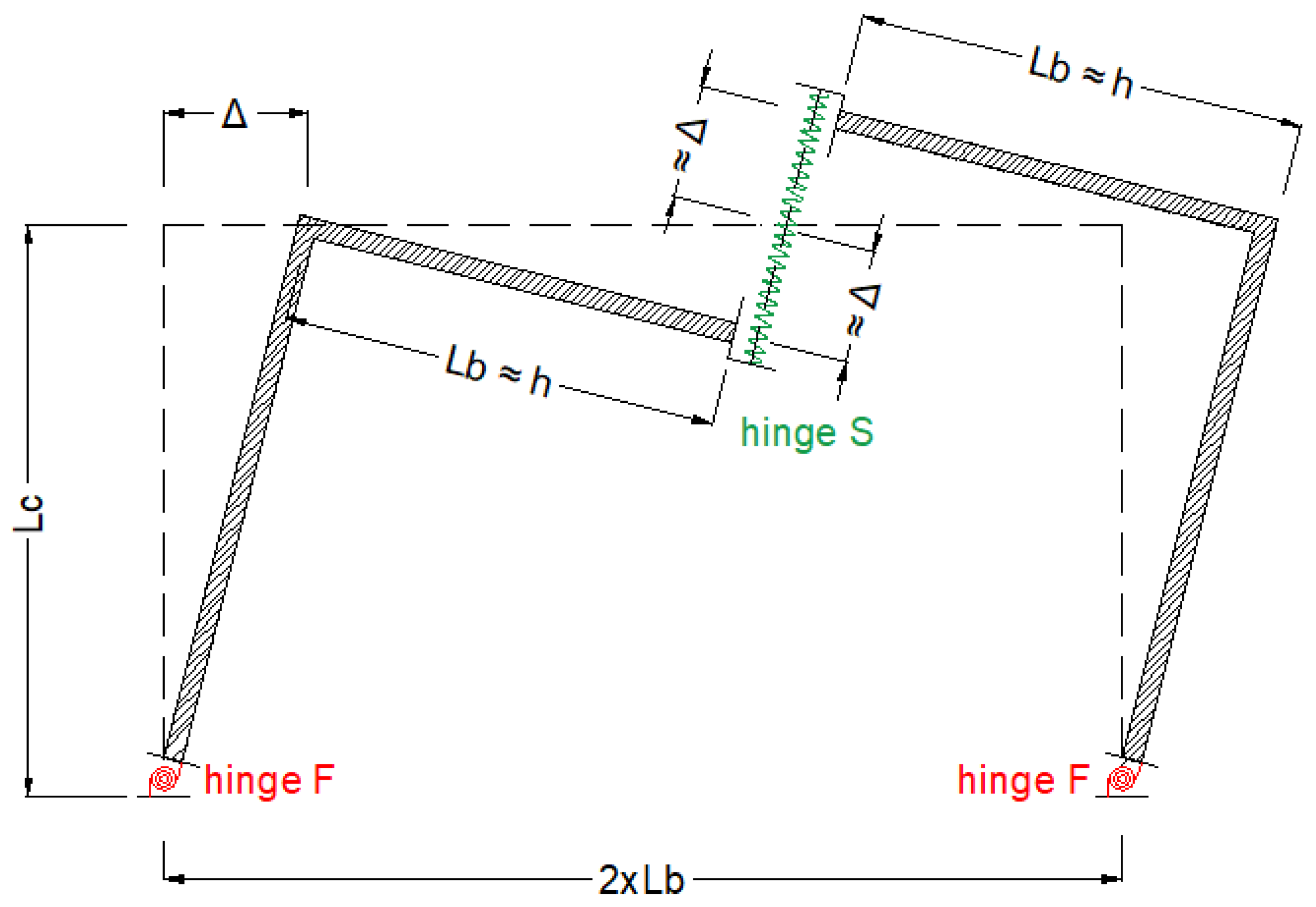
With reference to the one-bay, one-storey frame (portal) shown in Figure 3, in order to create a suitable kinematic mechanism under horizontal forces, dissipative devices are placed at the mid-point of the beam (device working under shear, hinge S) and at the base section of the columns (device working under flexural moment, hinge F). All the other new structural members (beams and columns and their connections) need to be designed as elastic.
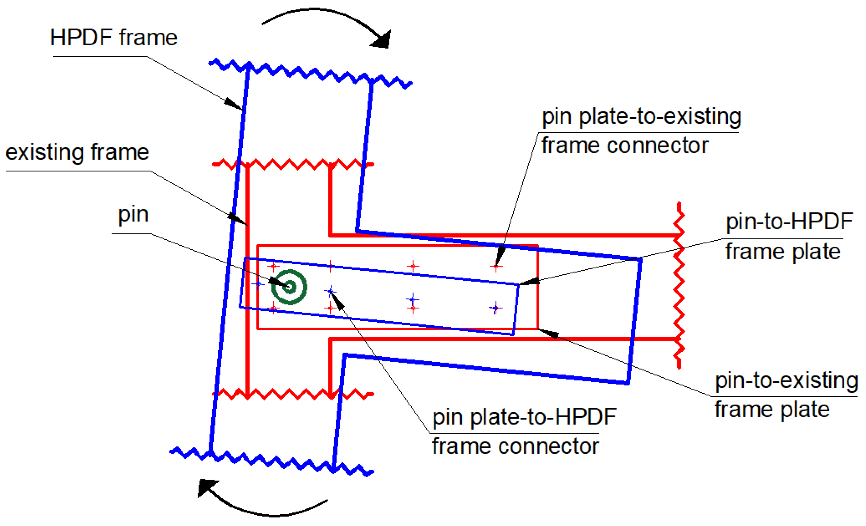
In order to allow the dissipative kinematic mechanism, different technical solutions can be adopted. Among these, the HPDF frames could be connected to the existing structure by means of pins placed at the beam-column intersections so that relative rotations are permitted, while horizontal/vertical displacements are restrained. Pins, in turn, could be fixed to both the new and existing RC members by means of common shear connectors properly designed and spread along the member length in order to transfer inertia forces between existing and new frames. Figure 4 shows a sketch of the new-to-existing frame connection.
As a result of the constitutive law of dampers, frames under horizontal forces can exhibit two different responses:
I.
for low- and mid-seismic intensity values, the new frames’ response is elastic, counteracting seismic actions by proper stiffness and strength values, duly designed in order to convey most lateral loads on them thus protecting the existing deficient structure;
II.
for high-seismic intensity values, dissipative devices simultaneously yield dissipating energy through hysteretic loops.
A purposely developed procedure is reported in Section 2.2 for designing the characteristics of the additional frames and of (local) damper parameters.
To this purpose, it is worth highlighting that dampers equipping the HPDF frames can rely on large displacement values compared to other passive control systems (e.g., dissipative braces, [19,20]). Indeed, by assuming a very high stiffness for the RC members compared to that of dissipating hinges, the vertical displacement value of the “free” end of each beam (i.e., where a dissipative shear device is placed, hinge S in Figure 3) can be evaluated as a function of both inter-storey drift and beam-to-column length ratio. As a result of the dimensions of both bay length and inter-storey height generally found in existing residential buildings (i.e., from 4.0 to 6.0 m for bay length and from 3.0 to 3.5 m for inter-storey height), vertical displacements can double the inter-storey (horizontal) drift value (Δ in Figure 3). Consequently, the shear device (e.g., [21,22]) along with the flexural one (e.g., [9,23]) equipping the HPDF system (i.e., F and S hinges in Figure 3) can dissipate a large amount of shaking energy. In general, in order to comply with the above-mentioned infinite-stiffness hypothesis, an elastic stiffness of RC members three-times greater the value of the corresponding hinges could be considered. Further, for high-rise buildings (i.e., number of storeys greater than six), low length of HPDF’s bays should be preferred. For the above described HPDF system, the patent application has been submitted.

2.2. Design Procedure of the HPDF System

In order to design HPDF frames, a generalized displacement-based procedure has been defined and described below. It uses non-linear static (push-over) analyses according to the N2 method [24] to determine both global and local (dampers) parameters of the system by iterating on the equivalent damping ratio value. The procedure consists of the following main steps.
Step 1: Push-over analysis and target displacement selection
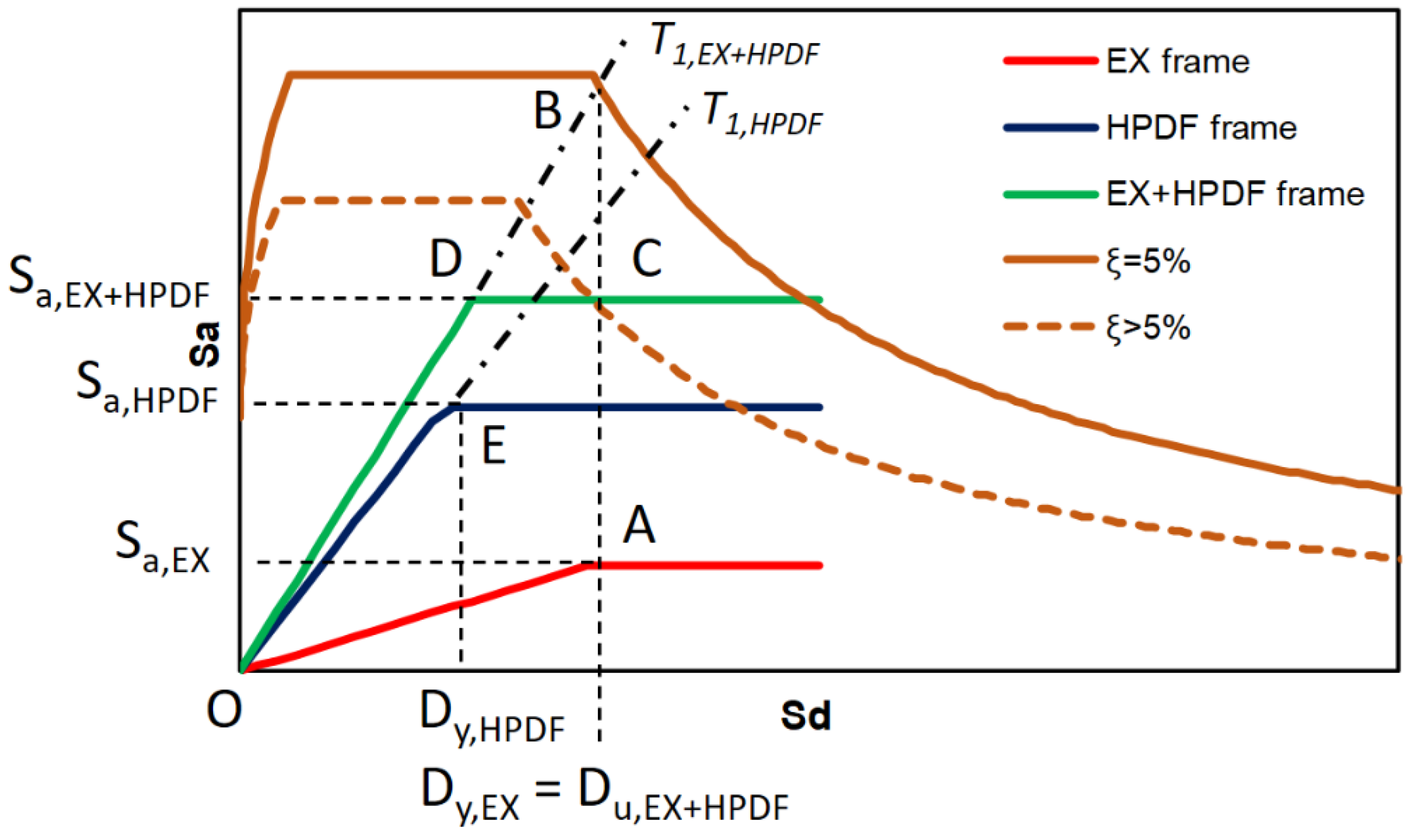
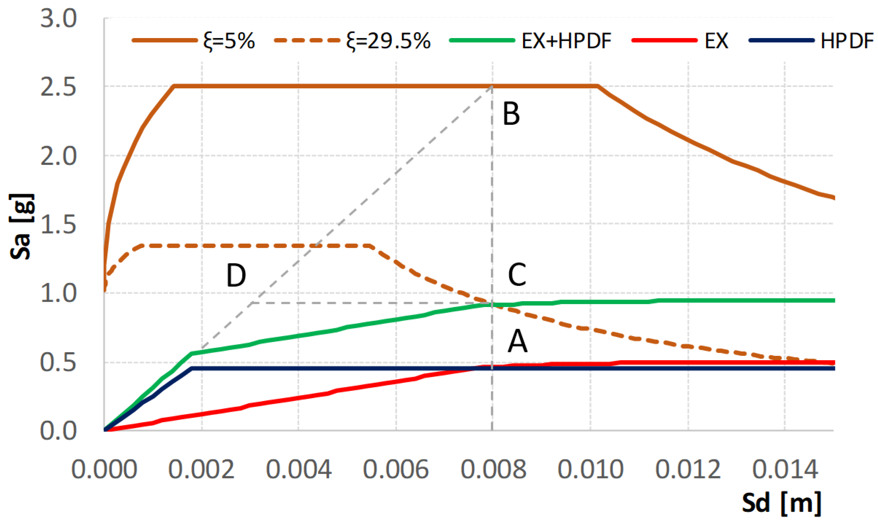
Nonlinear static (pushover) analyses on a multi degree of freedom (MDOF) model of the existing structure are carried out by using a suitable load pattern (e.g., [25,26]). The modal participation factor ([24]) is used to convert the MDOF response to the equivalent single degree of freedom (SDOF) one, and the related bilinear curve (red curve in Figure 5) is plotted in the acceleration-displacement response spectrum (ADRS) format (“capacity spectrum”).
At this point, the admitted target displacement value for the existing structure after seismic strengthening needs to be defined. To this purpose, due to the low ductility capacity generally available in non-seismically designed existing structures, it is advisable either to fix the target displacement value at the end of the elastic branch or, at the most, permit very low inelastic displacements. A further choice can be related to the occurrence of the first fragile crisis so as to avoid local strengthening interventions on the existing structure.
In Figure 5, the yielding value (Dy,EX, A point) on the bilinear curve referred to the existing structure is considered. The same value also represents the target displacement (so-called “performance point”) that will be considered in the design of the HPDF system (Du,EX+HPDF).
Step 2: Global stiffness of the retrofitted structure
The target displacement value of the existing structure (i.e., point A in Figure 5) is reported on the 5% damped spectrum (B point on the brown spectrum). In the ADRS format, the line connecting the origin (point O) to point B makes it possible to determine the vibration period value (T1,EX+HPDF) of the retrofitted structure. Note that the existing and HPDF system work in parallel.
Step 3: Strength and equivalent viscous damping ratio of the retrofitted structure
A first value of the equivalent viscous damping ratio ξ higher than that considered for the previous demand spectrum (i.e., ξ > 5%) is tentatively assumed, and the corresponding ADRS “reduced” demand spectrum is determined (dashed brown line in Figure 5). To this purpose, many damping reduction factors able to reduce spectral ordinates for high ξ values (i.e., much larger than 5%) are available in the literature (e.g., [27,28]). In order to determine strength (and in general the bilinear capacity curve of the retrofitted structure), starting from the target displacement value defined in Step 1 (i.e., point A), point C is determined on the “reduced” spectrum (dashed brown line in Figure 5). It represents the (trial) performance point for the retrofitted structure (i.e., existing plus HPDF frames).
By assuming no hardening for the retrofitted bilinear capacity curve, the line from point C to T1,EX+HPDF line determines the maximum strength value of the strengthened structure while point D is the yielding. Finally, the bilinear capacity curve of the retrofitted structure is drawn in green in Figure 5.
It is worth highlighting that the real value of the performance point (i.e., point C on the “reduced” spectrum) will be determined by an iterative procedure, as reported in the following.
Step 4: HPDF capacity spectrum
Keeping in mind that the HPDF frames and the existing structure work in parallel, the bilinear curve of the HPDF system (in blue in Figure 5) can be determined by subtracting the capacity spectrum values of the existing structure (in red in Figure 5) from those corresponding to the retrofitted one (green line in Figure 5). For the sake of simplicity, an approximative curve can be drawn by considering only the initial stiffness and yield force values.
Specifically, the initial global stiffness (K) value of the HPDF system is:
K HPDF = K EX + HPDF K EX
where each term is computed as follows:
K EX = F y , EX D y , EX = M · S a , EX D y , EX
K EX + HPDF = F y , EX + HPDF D y , EX + HPDF = M · S a , EX + HPDF D y , EX + HPDF
where Fy and Dy are the force and displacement value at the yielding, respectively. Fy can be also determined by multiplying the mass (M) to the pseudo-acceleration spectrum value corresponding to the fundamental period of vibration (Sa). To this purpose, a constant mass value can be assumed for the structure in both configurations (i.e., pre- and post-strengthening intervention).
Similarly, Fy for the HPDF system can be obtained as follows:
F y , HPDF = F y , EX + HPDF F y , EX
The Fy,HPDF to KHPDF ratio value determines the displacement value at yielding (Dy,HPDF), which will be used in Step 5.
Step 5: Damper properties
For a given in-plane direction of the building under strengthening, the required global stiffness (KHPDF) can be obtained as a sum of different HPDF systems working in parallel. Therefore, the following equation can be applied:
K HPDF = i = 1 n K HPDF , i
where K HPDF , i is the stiffness of the i-th HPDF frame.
This value is, in turn, obtained by summing the contribution of all hinges equipping the single HPDF frame (Figure 6). Specifically, by assuming a rigid-body behavior for the RC members of HPDF frame (i.e., structural deformation only depends on dampers), for the i-th HPDF frame having ns number of storeys (whose inter-storey height Lc is assumed as constant) and nb number of bays (i.e., related to nb + 1 number of columns), the following relationships between the global stiffness (KHPDF,i) and that relevant to the dissipative hinges (F and S in Figure 6) can be drawn:
K HPDF , i = j = 1 n b + 1 K F , j , i n s 2 · L c 2 + 2 · K SL , ij · L bL , j , i 2 n s · L c 2 + 2 · K SR , ij · L bR , j , i 2 n s · L c 2
where KF is the stiffness of the flexural hinges, KSL and KSR are the stiffness of the shear hinges at the left and right side of the j-th column, and LbL and LbR are the half-length of the beam members at the left and right side of the j-th column. Note that, for external columns, right or left beam length is zero, i.e., LbL = 0 or LbR = 0, and then the relative stiffness contribution in Equation (6) vanishes.
Because of the kinematic compatibility and aiming at defining an effective dissipative response (i.e., all hinges simultaneously yield), the following constraints should be applied:
-
flexural stiffness value is the same for all columns, i.e., KF,i,j = constant;
-
for a given shear hinge, KS value is the same for each beam at different storeys;
-
for a given beam between the j-th and j + 1-th columns, the shear hinges of the two part of beams (i.e., right and left) have the same stiffness value, i.e., KSL,j = KSR,j+1;
-
for the j-th column member, the following relationships between the shear stiffness of the dampers at the right and left side can be drawn:
K SR , j K SL , j = L bL , j L bR , j
Once the stiffness value of hinges are known (i.e., KF and KS), the yielding strength values (i.e., Fy,F and Fy,S) can be evaluated by multiplying KF and KS by the corresponding yielding displacement, v y,L and v y,R, for hinges SL and SR and chord rotation θy for hinge F. These latter values can be evaluated based on kinematic analyses. Specifically, with Δ as the generic roof displacement value (see Figure 3), according to the hypothesis of rigid behavior of the RC frame members, the rotation of the hinge F (θ) is equal to the ratio between Δ and the total column length:
θ = Δ n s · L c
Similarly, the orthogonal (to the beam axis) displacement value of hinge S ( v ) is:
v = 2 · ( L b n s · L c · Δ )
Note that, from Equation (7), the following relationship can be drawn between the vertical displacement and the corresponding beam lengths at the right and left site of the j-th column member:
v L , j v R , j = L bR L bL
In the case under description, the generic Δ value needs to be replaced by Dy,HPDF in order to obtain the required values for the other parameters.
Step 6: Actual damping value ratio
New push-over analyses are carried out on the retrofitted structure (i.e., existing structure plus HPDF system) until the selected displacement value of the performance point (point C in Figure 5, as evaluated in Step 3) is reached. In order to check the equivalent damping ratio ξ, the following expression proposed by Chopra [29] could be used:
ξ = 1 4 π · E D E S 0
where ED is the area of a hysteretic loop and ES0 is the corresponding maximum elastic strain energy. Additional expressions providing the equivalent damping ratio are reported in ([30,31,32]).
If the new value of ξ is within the acceptable tolerance (for example ±5%) with respect to that tentatively assumed (see Step 3), then the actual damping value is found and point C becomes the performance point of the retrofitted structure. On the contrary (i.e., the trial value of ξ is not within the acceptable tolerance), the damping ratio evaluated in this step is now considered in Step 3 and an iterative process is carried out until the difference between two consecutive steps is lower than the acceptable tolerance (i.e (ξi−ξi+1)/ξi ≤ ±5%).
Note that the new values of both performance point and damping ratio also determine different values of both capacity (and then damper parameters) and demand spectra.
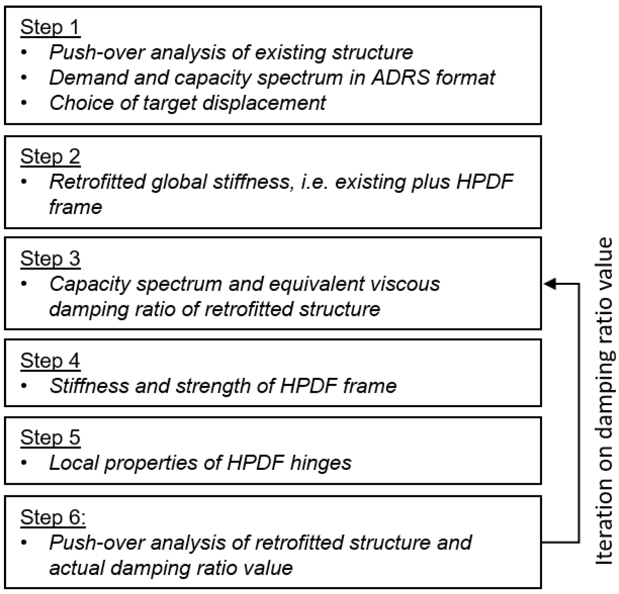
The flowchart in Figure 7 summarizes the above described procedure.

3. Numerical Application

In this section, non-linear analyses have been carried out on a 3D one-bay, one-storey RC frame retrofitted with the HPDF system. Numerical results make it possible to better illustrate the design procedure and understand the effectiveness of the system and its limitation of use.

3.1. Prototype Structure and Modeling

A 3D one-bay, one-storey frame structure has been considered as test example (Figure 8).
The prototype structure has a square shape in plan with total dimensions 5 × 5 m2 (X and Y direction, respectively) and inter-storey height equal to 3 m. All beams have a cross-section dimension equal to 0.30 × 0.50 m2 while columns are 0.30 × 0.30 m2.
For the above-described structure, finite element modelling (FEM) has been carried out using the OpenSees platform [33]. Specifically, a macro-modelling based on lumped plasticity has been adopted to describe the nonlinear seismic behavior of RC members. At both ends of each structural member, a bending moment–rotation (M-θ) relationship has been defined according to the Ibarra, Medina and Krawinkler model [34], available in OpenSees. Backbone parameters have been evaluated according to expressions provided by Haselton and Deierlein [35]. New-to-existing frame connections have been modeled by constraining the two adjacent corner nodes through the equalDOF constrain imposed along the horizontal displacements, while the relative rotations are free.
On the above described model, nonlinear static analyses (reverse) have been carried out. Hinge capacities have been evaluated by considering mean concrete strength value (fcm) equal to 20 MPa and mean steel strength value (fym) equal to 400 MPa.
Along the X direction, both global and local properties of the HPDF system have been evaluated according to the procedure reported in Section 2 and detailed in the following. Dampers at points F and S (Figure 8) have been modeled by considering uniaxial bilinear steel material without strain-hardening ratio. The HPDF’s RC frame members (both beams and columns) have been designed to remain elastic and, consequently, no plastic hinges have been considered. As better explained in the following, cross-section dimensions have been designed in order to comply as much as possible with the infinite-stiffness hypothesis. To this purpose, an elastic stiffness of members three times greater the value of the corresponding hinges is considered. As a result, the cross-section dimensions are 0.30 × 0.60 m2 for beams and 0.30 × 0.70 m2 for columns. A global mass equal to 250 tons has been considered.

3.2. Design and Non-Linear Analysis Results

According to the procedure described in Section 2.2, for the prototype structure under study non-linear static (push-over, PO) analyses have been carried out. In Figure 9 (red line), the PO curve obtained for the X-direction is reported in the ADRS format (capacity spectrum in the following). An EC-8 code-conforming 5% damped spectrum is also plotted (demand spectrum, brown line in Figure 9).
The target displacement has been assumed equal to the yielding displacement of the existing structure (Dy,EX = 8 mm, point A). This value is reported on the demand spectrum (point B) in order to evaluate the stiffness value of the retrofitted structure (KEX+HPDF), which is a function of the slope of the line connecting the origin to point B. Specifically, it is:
K EX + HPDF = 78 , 100   kN / m
As for the strength of the retrofitted structure, starting from the target displacement A, the corresponding point C on the reduced spectrum demand (i.e., ξ larger than 5%) can be drawn. After that, the horizontal branch from point C to line OB determines point D, which represents the yielding displacement of the strengthened structure. As reported above, both points C and D depend on the considered ξ value, which is determined by the iterative procedure described in Section 2.2. In this example, at the end of the iterative process, the actual value of ξ is 29.5% and then the ductility demand (target to yielding displacement ratio) is about 2.7.
In order to compute the ordinates of the reduced spectrum, the expression by Bommer et al. [27], also adopted by the EC8 code [36], has been considered.
By subtracting the capacity spectrum of the existing one (red line in Figure 9) from that of the retrofitted structure (green line) the capacity curve of the HPDF system (blue line) is obtained (for design scope, a linearization of the results needs to be done).
Specifically, the stiffness (K) and the strength at yield Fy values related to only one HPDF frame (note that there are two HPDF systems, one for each side of the considered prototype) are:
K HPDF = 1 2 ( K EX + HPDF K EX ) = 1 2 ( 78 , 100 15 , 000 ) = 31 , 550   kN / m
F y , HPDF = 1 2 ( F y , EX + HPDF F y , EX ) = 1 2 ( 235 125 ) = 55   kN
As a result, the displacement at yielding (Dy,HPDF) is obtained from:
D y , HPDF = F y , HPDF K HPDF = 1.7 · 10 3   m
The stiffness of the dissipative hinges (i.e., F and S, in Figure 8) is evaluated by Equation (6), which becomes as follows:
K HPDF = ( 2 · K F L c 2 + 4 · K S · L b 2 L c 2 )
where Lc = 3 m and Lb = 2.5 m are the column and half-beam length, respectively.
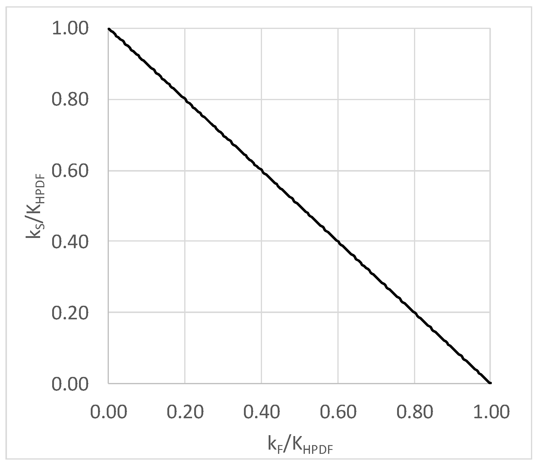
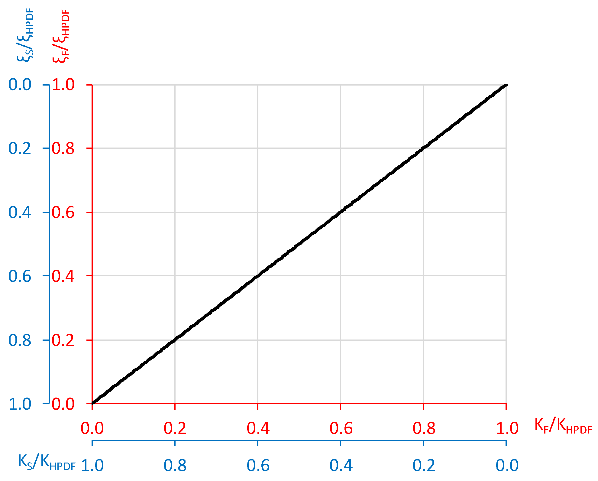
Different values of the hinge stiffness can be made. To this purpose, Figure 10 reports the relationship between the first term of Equation (12) (i.e., stiffness of the flexural hinge, KF, normalized to the global stiffness, KHPDF) and the second one (i.e., stiffness of the shear hinge, KS, normalized to the global stiffness, KHPDF). It is worth noting that the considered frame has two flexural hinges, thus each one provides half of the flexural stiffness contribution to the global deformation. For example, in case the same contribution to the global stiffness is considered (i.e., K F K HPDF = K S K HPDF = 0.5 ).
In the following, KS = 5.7·103 kN/m and KF = 7.1·104 kNm are considered.
The strength at yielding (FS,y and MF,y, respectively, for S and F hinge) are obtained by multiplying KF and KS to the corresponding yielding displacement, in terms of chord rotation (θy,F) for the flexural hinge and vertical displacement ( v y,S) for the shear one. According to Equations (8) and (9), in order to achieve a simultaneous yielding of all hinges, the following values have been considered for θy,F and v y,S:
θ y , F = ( D y , HPDF L c ) = 5.94 · 10 4
v y , S = 2 · ( L b L c · D y , HPDF ) = 2.97   mm
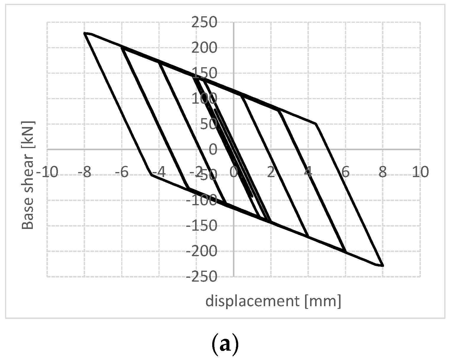
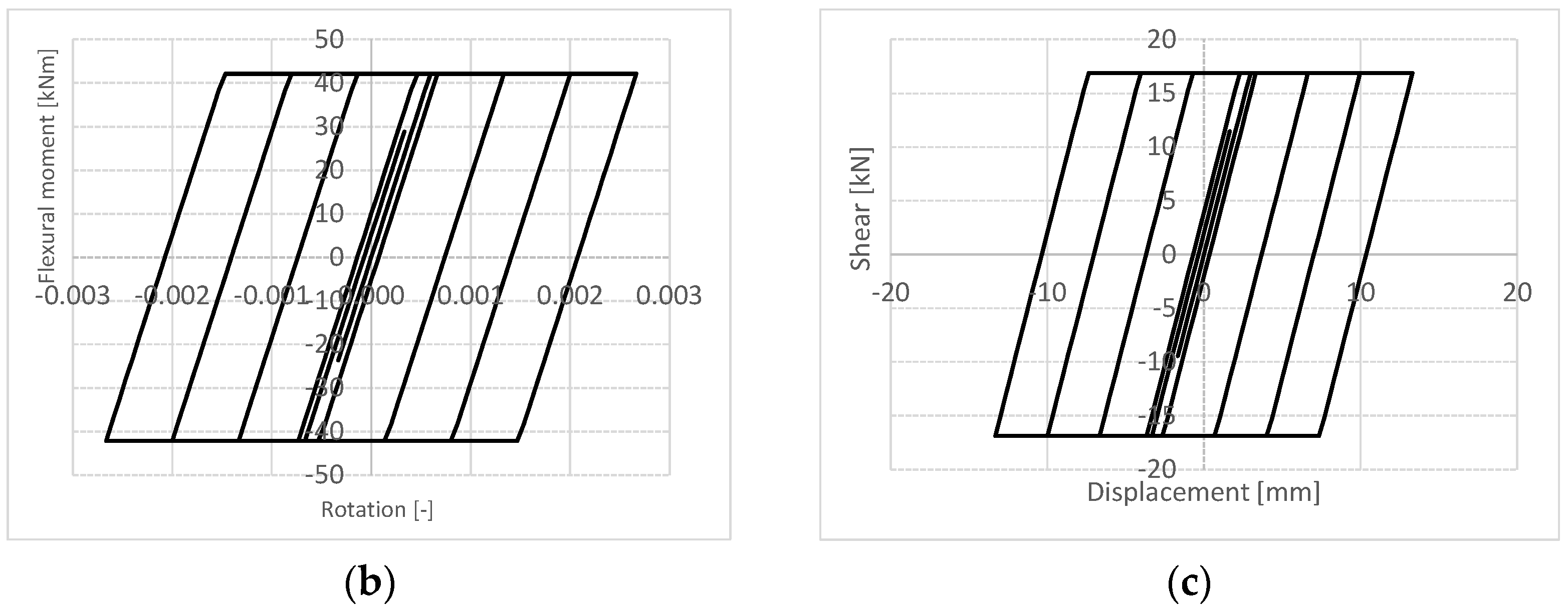
As above mentioned, by iterating on ξ values, the actual value of equivalent damping ratio has been detected, equal to 29.5%. To this purpose, the expression provided by Mazza and Vulcano [30] has been adopted. Figure 11a shows the cyclic response of the retrofitted structures pushed up to the target displacement value (8 mm), while Figure 11b,c report the response of the flexural and shear hinge, respectively.
In the case under description, the response of the existing structure is elastic, and the hysteretic dissipation is only due to the hinges of the HPDF system. The contribution to the total hysteretic energy of each type of device, i.e., flexural and shear one, is a function of their constitutive law. In order to better understand the role of some parameters of the devices on the dissipative characteristics, Figure 12 shows the relationship between the stiffness of both flexural and shear hinge (note that KF and KS are normalized to the global stiffness, KHPDF) and the corresponding equivalent damping ratio (normalized to the global value, ξHPDF). As can be expected, the equivalent damping ratio relevant to a given hinge linearly increases with its relative stiffness value. In case the two types of devices have the same relative stiffness value, i.e., K F K HPDF = K S K HPDF = 0.5 , the relative contribution to the dissipated energy is the same, i.e., ξ F ξ HPDF = ξ S ξ HPDF = 0.5 . Nevertheless, it is worth noting that, in the case under study, there are two flexural hinges and one shear hinge. Consequently, the dissipated energy due to the shear hinge is double that of each flexural one.

4. Conclusions

This study describes the High-Performance Dissipating Frame (HPDF) system representing an effective seismic strengthening solution, especially for existing RC structures designed only to vertical loads. The main novelty of the newly proposed technique, compared to traditional exoskeletons systems, lies in the presence of additional dissipative (shear and flexural) devices, whose location is properly defined in order to amplify their dissipative contribution.
In the paper, the HPDF system has been described and a displacement-based design method has been purposely developed. The design method permits evaluating, in an easy and reliable way, the global properties of the new strengthening frame such as stiffness, strength and equivalent damping ratio as well the local properties of dissipative hinges. Specifically, an iterative procedure based on selected damping ratio values has been set up by adopting non-linear static (push-over) analyses, commonly used in design practice.
The design method has been applied to a simple structure in order to provide suggestions for designing the two types of dampers (i.e., shear and flexural one) equipping the HPDF device. The response of the two types of dampers is found inversely proportional, that is, the greater the stiffness of flexural hinge, the lower the stiffness of the shear one, and vice versa. By setting the elastic response for the existing structure and the same relative stiffness value for the two types of dampers (with respect to the total stiffness), a high value of the equivalent damping ratio (equal to 29.5%) has been found, where the contribution of the shear damper is double that of each flexural damper. This highlights the key role of the shear damper in characterizing the new strengthening system.
With respect to future research activities, the conceptualization of the HPDF system presented in this study will be supported by a wide experimental program able to better address its development and effectiveness. This experimental validation will be followed by applications to real building models in order to define its applicability to different RC building types.

Author Contributions

All authors have equally contributed to the different aspects of the reported research through a synergic collaboration and continuous reciprocal feedback. All authors have read and agreed to the published version of the manuscript.

Funding

This research received no external funding.

Institutional Review Board Statement

Not applicable.

Informed Consent Statement

Not applicable.

Data Availability Statement

Not applicable.

Acknowledgments

This study was partially developed under the financial support of the Italian Department of Civil Protection, within the ReLUIS-DPC 2019–2021 project. This support is gratefully acknowledged.

Conflicts of Interest

The authors declare no conflict of interest.

References

  1. ISTAT. 2011: XV Censimento Generale Della Popolazione e Delle Abitazioni. Available online: www.istat.it.
  2. Masi, A.; Chiauzzi, L.; Santarsiero, G.; Manfredi, G.; Biondi, S.; Spacone, E.; Del Gaudio, C.; Ricci, P.; Manfredi, G.; Verderame, G.M. Seismic response of RC buildings during the Mw 6.0 August 24, 2016 Central Italy earthquake: The Amatrice case study. Bull. Earthq. Eng. 2019, 17, 5631–5654. [Google Scholar] [CrossRef]
  3. BPIE (Building Performance Institute Europe). Europe’s Buildings under the Microscope—A Country-By-Country Review of the Energy Performance of the Buildings. Brussel. 2011. Available online: http://www.bpie.eu/eu_buildings_under_microscope.html.
  4. Bournas, D. Innovative Materials for Seismic and Energy Retrofitting of the Existing EU Buildings; EUR 29184 EN.; Publications Office of the European Union: Luxembourg, 2018. [Google Scholar]
  5. UNDRR and CRED. The human cost of disasters: An overview of the last 20 years (2000–2019), Centre for Research on the Epidemiology of Disasters, 2020, UN Office for Disaster Reduction. Available online: https://reliefweb.int/.
  6. Calvi, G.M. Choices and Criteria for Seismic Strengthening. J. Earthq. Eng. 2013, 17, 769–802. [Google Scholar] [CrossRef]
  7. FIB. Seismic Assessment and Retrofit of Reinforced Concrete Buildings; Bulletin No. 24; International Federation for Structural Concrete: Lausanne, Switzerland, 2003. [Google Scholar] [CrossRef]
  8. Fardis, M.N. Seismic Design, Assessment and Retrofitting of Concrete Buildings: Based on EN-Eurocode 8; Springer Science & Business Media: Cham, The Netherlands, 2009. [Google Scholar]
  9. Santarsiero, G.; Manfredi, V.; Masi, A. Numerical evaluation of the Steel Plate Energy Absorption Device (SPEAD) for Seismic Strengthening of RC Frame Structures. Int. J. Civ. Eng. 2020, 18, 835–850. [Google Scholar] [CrossRef]
  10. Masi, A.; Manfredi, V.; D’Angola, A.; Laguardia, A. Seismic and thermal rehabilitation of existing RC buildings through an integrated approach: An application case study. In Proceedings of the XVII Convegno ANIDIS-L’ingegneria Sismica in Italia, Pistoia, Italy, 17–21 September 2017. [Google Scholar]
  11. Pertile, V.; Stella, A.; De Stefania, L.; Scotta, R. Experimental tests on full-scale specimens for the characterization of an integrated retrofitting system for existing buildings. In Proceedings of the XVIII Convegno ANIDIS-L’ingegneria Sismica in Italia, Ascoli Piceno, Italy, 15–19 September 2019. [Google Scholar]
  12. Gkournelos, P.D.; Bournas, D.A.; Triantafillou, T.C. Combined seismic and energy upgrading of existing reinforced concrete buildings using TRM jacketing and thermal insulation. Earthq. Struct. 2019, 16, 625–639. [Google Scholar]
  13. Labò, S.; Passoni, C.; Marini, A.; Belleri, A. Design of diagrid exoskeletons for the retrofit of existing RC buildings. Eng. Struct. 2020, 220, 110899. [Google Scholar] [CrossRef]
  14. Sustersic, I.; Dujic, B. Seismic Strengthening of Existing Concrete and Masonry Buildings with Crosslam Timber Panels. RILEM Bookseries 2014, 9, 713–723. [Google Scholar] [CrossRef]
  15. Manfredi, V.; Masi, A. Seismic strengthening and energy efficiency: Towards an integrated approach for the rehabilitation of existing RC buildings. Buildings 2018, 8, 36. [Google Scholar] [CrossRef] [Green Version]
  16. Manfredi, V.; Masi, A.; Ventura, G.; Chiauzzi, L.; Digrisolo, A.; Santarsiero, G. Rafforzamento sismico degli edifici esistenti in c.a. una soluzione innovativa per interventi integrati e sostenibili. Structural 2018, 215. [Google Scholar] [CrossRef]
  17. Zanni, J.; Marini, A.; Belleri, A.; Riva, P.; Simonetti, F. Integrated rehabilitation with exoskeleton under a life cycle thinking approach: Application to an existing building. In Proceedings of the XXVII Congresso, C.T.A., Bologna, Italy, 3–5 October 2019. [Google Scholar]
  18. Whittaker, A.; Bertero, V.; Alonso, J.; Thompson, C. Earthquake Simulator Testing of Steel Plate Added Damping and Stiffness Elements; Report Number: UCB/EERC 89/02; Earthquake Engineering Research Center, University of California: Berkeley, CA, USA, 1988. [Google Scholar] [CrossRef]
  19. Constantinou, M.C.; Soong, T.T.; Dargush, G.F. Passive Energy Dissipation Systems for Structural Design and Retrofit, MCEER Monograph No.1; Multidisciplinary Center for Earthquake Engineering Research: Buffalo, NY, USA, 1998.
  20. Ye, Q.; Wang, Z.; Wang, Y. Numerical study on seismic performance of prefabricated steel frames with recentering energy dissipative braces. Eng. Struct. 2020, 207, 110223. [Google Scholar] [CrossRef]
  21. Symans, M.D.; Charney, F.A.; Whittaker, A.S.; Constantinou, M.C.; Kircher, C.A.; Johnson, M.W.; McNamara, R.J. Energy dissipation systems for seismic applications: Current practice and recent developments. J. Struct. Eng. 2008, 134, 3–21. [Google Scholar] [CrossRef] [Green Version]
  22. Nuzzo, I.; Losanno, D.; Caterino, N.; Serino, G.; Bozzo, L.M. Experimental and analytical characterization of steel shear links for seismic energy dissipation. Eng. Struct. 2017, 172, 405–418. [Google Scholar] [CrossRef]
  23. Ponzo, F.C.; Di Cesare, A.; Nigro, D.; Vulcano, A.; Mazza, F.; Dolce, M.; Moroni, C. Jet-Pacs Project: Dynamic Experimental Tests and Numerical Results Obtained for a Steel Frame Equipped with Hysteretic Damped Chevron Braces. J. Earthq. Eng. 2012, 16, 662–685. [Google Scholar] [CrossRef]
  24. Fajfar, P. A nonlinear analysis method for performance based seismic design. Earthq. Spectra 2000, 16, 573–592. [Google Scholar] [CrossRef]
  25. Antoniou, S.; Pinho, R. Development and verification of a displacement-based adaptive pushover procedure. J. Earthq. Eng. 2004, 8, 643–661. [Google Scholar] [CrossRef]
  26. Chopra, A.K.; Goel, R.K. A modal pushover analysis procedure for estimating seismic demands for buildings. Earthq. Eng. Struct. Dyn. 2002, 31, 561–582. [Google Scholar] [CrossRef] [Green Version]
  27. Bommer, J.J.; Mendis, R. Scaling of spectral displacement ordinates with damping ratios. Earthq. Eng. Struct. Dyn. 2005, 34, 145–165. [Google Scholar] [CrossRef]
  28. Rezaeian, S.; Bozorgnia, Y.; Idriss, I.M.; Abrahamson, N.; Campbell, K.; Silva, W. Damping Scaling Factors for Elastic Response Spectra for Shallow Crustal Earthquakes in Active Tectonic Regions: “Average” Horizontal Component. Earthq. Spectra 2014, 30, 939–963. [Google Scholar] [CrossRef]
  29. Chopra, A.K. Dynamics of Structures: Theory and Applications to Earthquake Engineer, 4th ed.; Hall, J.W., Ed.; Series in Civil Engineering and Engineering Mechanics; Prentice-Hall International: Upper Saddle River, NJ, USA, 2012. [Google Scholar]
  30. Mazza, F.; Vulcano, A. Displacement-based design procedure of damped braces for the seismic retrofitting of R.C. framed buildings. Bull. Earthq. Eng. 2015, 13, 2121–2143. [Google Scholar] [CrossRef]
  31. Priestley, M.J.N.; Grant, D.N. Viscous damping in seismic design and analysis. J. Earthq. Eng. 2005, 9 (Suppl. S2), 229–255. [Google Scholar] [CrossRef]
  32. Nuzzo, I.; Losanno, D.; Caterino, N. Seismic design and retrofit of frame structures with hysteretic dampers: A simplified displacement-based procedure. Bull. Earthq. Eng. 2019, 17, 2787–2819. [Google Scholar] [CrossRef]
  33. McKenna, F. OpenSees: A framework for earthquake engineering simulation. Comput. Sci. Eng. 2011, 13, 58–66. [Google Scholar] [CrossRef]
  34. Ibarra, L.F.; Medina, R.A.; Krawinkler, H. Hysteretic models that incorporate strength and stiffness deterioration. Earthq. Eng. Struct. Dyn. 2005, 34, 1489–1511. [Google Scholar] [CrossRef]
  35. Haselton, C.B.; Deierlein, G.G. Assessing Seismic Collapse Safety of Modern Reinforced Concrete Moment Frame Buildings. Ph.D. Thesis, Stanford University, Stanford, CA, USA, February 2007. [Google Scholar]
  36. Comité Européen de Normalisation. CEN-European Standard ENV 1998-1-1/2/3, Eurocode 8: Design Provisions for Earthquake Resistance of Structures—Part I: General Rules; Technical Committee 250/SC8; Comité Européen de Normalisation: Brussels, Belgium, 2004. [Google Scholar]
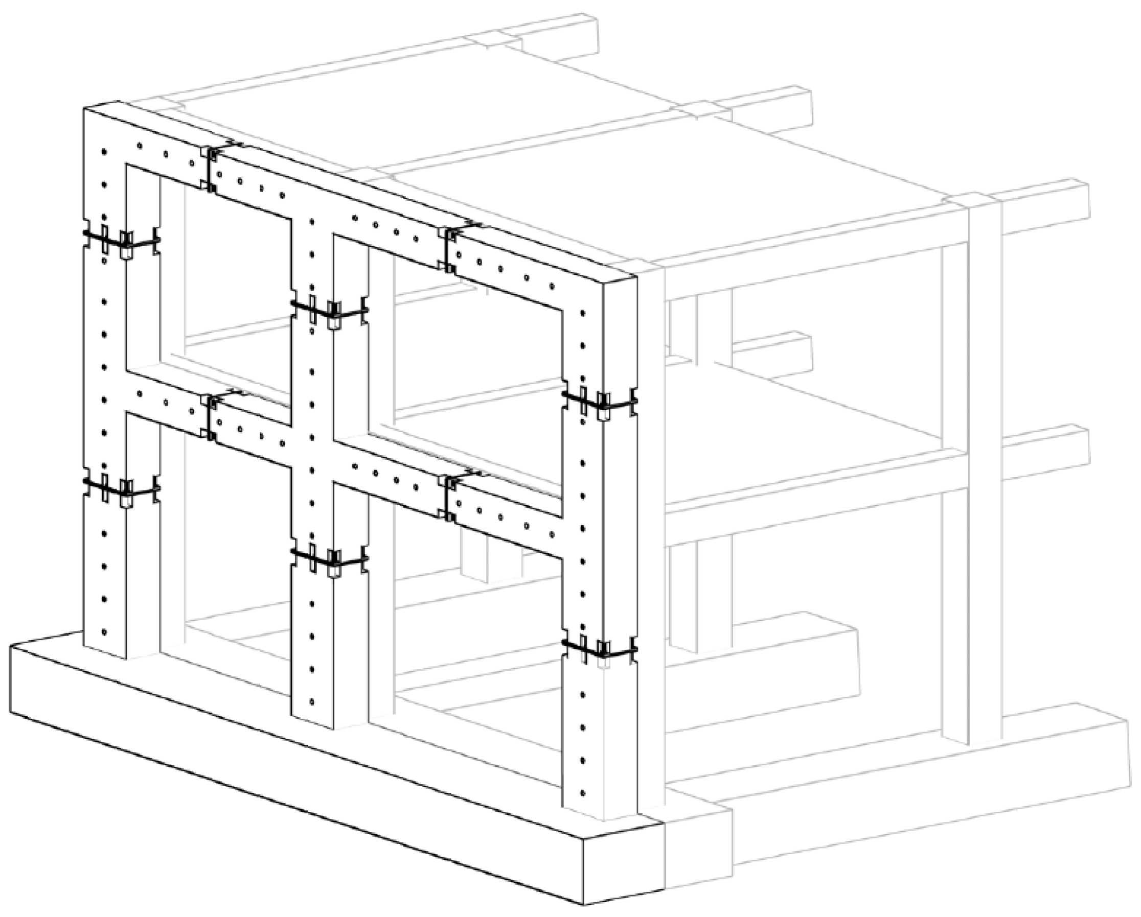
Figure 1. 3D view of the strengthening frames proposed in [16].
Sustainability 13 01864 g001
Figure 2. Knee-joint (a), tee-joint (b,c) and cruciform joint (d) of the precast strengthening frame proposed in [16].
Sustainability 13 01864 g002
Figure 3. Location of flexural (F) and shear (S) hinges for a one-bay, one-storey frame.
Sustainability 13 01864 g003
Figure 4. Sketch of new-to-existing frame connection.
Sustainability 13 01864 g004
Figure 5. Design procedure of the High-Performance Dissipating Frame (HPDF) frames in the acceleration-displacement response spectrum (ADRS) format.
Sustainability 13 01864 g005
Figure 6. Sketch of a multi-bay, multi-storey HPDF frame.
Sustainability 13 01864 g006
Figure 7. Flowchart of the design procedure.
Sustainability 13 01864 g007
Figure 8. Prototype of existing structure (in black) and HPDF device (in blue).
Sustainability 13 01864 g008
Figure 9. Demand and capacity spectra for the considered example according to the ADRS format.
Sustainability 13 01864 g009
Figure 10. Relationship between KF and KS hinges (normalized by the KHPDF global stiffness).
Sustainability 13 01864 g010
Figure 11. Cyclic push-over results: base shear vs. displacement (a), flexural moment vs. rotation of F hinge (b) and shear vs. displacement of S hinge (c) relationships.
Sustainability 13 01864 g011aSustainability 13 01864 g011b
Figure 12. Relationship between the stiffness of both flexural and shear hinges (KF and KS are normalized to the global stiffness, KHPDF) and the corresponding equivalent damping ratio (normalized to the global value, ξHPDF).
Sustainability 13 01864 g012
Publisher’s Note: MDPI stays neutral with regard to jurisdictional claims in published maps and institutional affiliations.