Article

Latent Heat Phase Change Heat Transfer of a Nanoliquid with Nano–Encapsulated Phase Change Materials in a Wavy-Wall Enclosure with an Active Rotating Cylinder

by
S. A. M. Mehryan
1,
Kaamran Raahemifar
2,3,4,5,
Leila Sasani Gargari
6,
Ahmad Hajjar
7,
Mohamad El Kadri
8,
Obai Younis
9,10 and
Mohammad Ghalambaz
11,12,*
1
Young Researchers and Elite Club, Yasooj Branch, Islamic Azad University, Yasooj 7591493686, Iran
2
College of Information Sciences and Technology (IST), Data Science and Artificial Intelligence Program, Penn State University, State College, Pennsylvania, PA 16801, USA
3
Department of Chemical Engineering, Faculty of Engineering, University of Waterloo, 200 University Ave. W, Waterloo, ON N2L 3G1, Canada
4
School of Optometry and Vision Science, Faculty of Science, University of Waterloo, 200 University Ave. W, Waterloo, ON N2L 3G1, Canada
5
Electrical and Computer Engineering Department, Sultan Qaboos University, Al-Khoud, Muscat 123, Oman
6
Department of Mechanical Engineering, Shahid Beheshti University, Tehran 1651153311, Iran
7
ECAM Lyon, LabECAM, Université de Lyon, 69007 Lyon, France
8
Centre Scientifique et Technique du Bâtiment, 44323 Nantes, France
9
Department of Mechanical Engineering, College of Engineering at Wadi Addwaser, Prince Sattam Bin Abdulaziz University, Wadi Addwaser 11991, Saudi Arabia
10
Department of Mechanical Engineering, Faculty of Engineering, University of Khartoum, Khartoum 11111, Sudan
11
Metamaterials for Mechanical, Biomechanical and Multiphysical Applications Research Group, Ton Duc Thang University, Ho Chi Minh City 758307, Vietnam
12
Faculty of Applied Sciences, Ton Duc Thang University, Ho Chi Minh City 758307, Vietnam
*
Author to whom correspondence should be addressed.
Sustainability 2021, 13(5), 2590; https://doi.org/10.3390/su13052590
Submission received: 23 January 2021 / Revised: 7 February 2021 / Accepted: 9 February 2021 / Published: 1 March 2021

Abstract

:
A Nano-Encapsulated Phase-Change Material (NEPCM) suspension is made of nanoparticles containing a Phase Change Material in their core and dispersed in a fluid. These particles can contribute to thermal energy storage and heat transfer by their latent heat of phase change as moving with the host fluid. Thus, such novel nanoliquids are promising for applications in waste heat recovery and thermal energy storage systems. In the present research, the mixed convection of NEPCM suspensions was addressed in a wavy wall cavity containing a rotating solid cylinder. As the nanoparticles move with the liquid, they undergo a phase change and transfer the latent heat. The phase change of nanoparticles was considered as temperature-dependent heat capacity. The governing equations of mass, momentum, and energy conservation were presented as partial differential equations. Then, the governing equations were converted to a non-dimensional form to generalize the solution, and solved by the finite element method. The influence of control parameters such as volume concentration of nanoparticles, fusion temperature of nanoparticles, Stefan number, wall undulations number, and as well as the cylinder size, angular rotation, and thermal conductivities was addressed on the heat transfer in the enclosure. The wall undulation number induces a remarkable change in the Nusselt number. There are optimum fusion temperatures for nanoparticles, which could maximize the heat transfer rate. The increase of the latent heat of nanoparticles (a decline of Stefan number) boosts the heat transfer advantage of employing the phase change particles.

1. Introduction

Enhancing convective heat transfer has become a key element in various industrial applications. Employing suspended nanoparticles is a widely used technique to increase thermal conductivity and convective heat transfer coefficient in comparison to pure liquids or liquids with large particles [1,2]. Wen et al. [3] investigated the free convective heat transfer of aqueous-based titanium-dioxide nanofluids with different concentrations experimentally. Sheikholeslami et al. [4] analyzed the free convection of magnetizable hybrid nanofluid free convection in a circular enclosure with two circular heaters. These studies showed that the inclusion of nanoparticles with in the host fluid enhances the heat transfer. The convective heat transfer of nanofluids has been explored in some of recent publications such as [5,6].
Moreover, convection in conductive porous media is an effective technique to improve heat transfer [7,8,9]. Sun et al. [10] studied steady-state free convective behavior of nanofluids inside a right-angle triangular cavity full of porous medium. The maximum value of the average Nusselt number was achieved by reducing the cavity aspect ratio and allocating the heater at a lower position while keeping both the Rayleigh number and the heater size at their largest values. Chamkha et al. [11] studied the conjugate free convection-conduction heat transfer in a square domain consisted of nanofluids filled porous cavity. The cavity was heated by a solid triangular wall under steady-state conditions. These studies indicated that the increment of nanoparticles volumetric fraction at a low Rayleigh number (Ra = 10) significantly enhanced the heat.
Several other studies dealt with forced convection. Sheikholeslami [12] investigated forced convection heat transfer in a lid-driven porous cavity. Copper oxide nanoparticles were suspended in water to synthesize a nanofluid. He reported that using Platelet shaped nanoparticles increased the Nusselt number and heat transfer was improved by an incline of Darcy and Reynolds numbers and a decline of Hartmann number. Xuan and Li [13] studied forced convective heat transfer and flow features of the nanofluid in a tube. Wen and Ding [14] studied the laminar convective heat transfer of nanofluids, composed of γ-Al2O3 nanoparticles and de-ionized water, flowing throughout a copper tube. Hwang et al. [15] performed experimental measurements to study convective heat transfer of water-based Al2O3 nanofluids flowing throughout an evenly heated circular tube in the fully developed laminar flow regime. In general, nanofluids have been confirmed to magnify convective heat transfer in various flow configurations [16].
Recently, the technology of Phase Change Materials PCMs has been utilized in devices made of materials presenting a high risk of temperature gradients and having different thermal expansion coefficients. PCMs are capable of absorbing and releasing heat energy as they experience phase change process from solid to liquid, and vice versa [17]. PCMs are used in several fields such as energy conservation [18], exchangers [19] and electronic devices [20]. Several researchers used the PCM in different engineering systems for sustainable development. Isa et al. [21] numerically and experimentally investigated PCM usage and copper foam in passive cooling for enhancing thermal heat storage in buildings. As the study was performed in Malaysia, the authors selected terrace houses as a case-study. They found that the house’s cooling loads were dramatically reduced when the existing materials were integrated with PCM and copper foam. Baek et al. [22] used a PCM layer in a radiant floor heating system and attempted to determine the optimum temperatures of hot water to reduce heat consumption. The model studied floor consisted of a 10 mm PCM layer, Autoclaved lightweight concrete, concrete slabs, insulating material, and mortar. The hot water’s optimum temperature was found to be in the range of 40–41 °C. González-Peña et al. [23] attempted to control the PV panel temperature by introducing a PCM tank on the panel’s backside. The author analyzed the performance of the new proposed system by using experimental techniques and numerical methods. The proposed system achieved 50% of the global daily average efficiency. It is worth mentioning that this proposed design was patented.
However, the common problem of the PCMs is their low thermal conductivity. Metal foams [24] are a promising material for enhancing heat transfer. Calmidi et al. [25] researched the forced convection in high porosity metal foams by means of numerical simulations and experimental techniques. Zhao et al. [26] investigated free convection in open-celled metal foams. These studies were limited to single-phase heat transfer problems. Zhao et al. [27] inspected the solid/liquid phase change (melting and solidification) processes in metal foams. The PCM used was the Paraffin wax RT58. The influence of metal foam on solid/liquid phase change heat transfer was of great importance, in comparison with the pure PCM sample results, particularly at the solid zone of PCMs. Siahpush et al. [28] undertook analytical and experimental investigations to evaluate the impact of using copper porous foam on the heat transfer performance in a cylindrical solid/liquid phase change thermal energy storage system. The foam increased the effective thermal conductivity from 0.423 W/m K to 3.06 W/mK.
The use of Nano Encapsulated Phase Change Materials (NEPCM) suspensions, as a new type of nanofluids, is promising to enhance heat transfer in natural and forced convection flows. NEPCM particles, composed of a core of PCMs and a protective shell material, are made of polymers such as polymer-SiO2 [29,30] and TiO2 [31,32]. In the recent few years, research was mainly targeted to the hybrid shell, which combines the merits of both organic and inorganic materials, to enhance remarkably heat transfer [33]. The NEPCMs are synthesized by several techniques such as layer-by-layer (LbL) assembly [34,35], spray drying [36], and interfacial polymerization [37,38]. Rodriguez-Cumplido et al. [39] showed that the modification of the shell composition could magnify the thermal conductivity of PCMs. The NEPCM suspensions is proven to be very effective in heat transfer improvement.
Huu-Quan et al. [40] explored the advantage of using NEPCMs in finned enclosures. The outcomes show that the rise of particle volume fraction could lead to heat transfer enhancement in finned enclosures.
On the other hand, mixed convection with a rotating cylinder has multiple applications, for example, multi shield structures used in nuclear reactors, high-performance building insulation, in electronic device cooling, furnaces, solar power collectors, glass production, food processing, and drying technologies [41]. The rotation of the cylinder induces mixed convection, which is the result of buoyancy forces due to the temperature gradient combined with forced convection due to the shear forces imposed by the rotating cylinder. The complexity of the analysis of mixed convection is because of the complicated interaction between the free convection with the shear driven flow. Due to the importance of such mixed convection flows, they have been reported in some recent publications. The mixed convection flow and heat transfer of CNT [42] and CuO [43] nanofluids in a cavity with an inner rotating circular cylinder are examples of such phenomena. It was noticed that the average heat transfer is directly proportional to Richardson’s number, cylinder angular rotational speed, and volume fraction of nanoparticles.
The wavy wall enclosures have found crucial applications in heat exchangers and solar collectors. The wavy surface provides an extended heat transfer area and hydraulic interaction. Hence, the convection heat transfer in wavy wall enclosures has grabbed the attention of some recent researches. For example, the wavy wall enclosures containing inner cylinder [44], wavy wall cavities full of a porous medium, and Al2O3-water nanofluid [45], cavities with a lid-driven [46] and a porous wavy enclosure full of a nanofluid [47] have been investigated recently.
The previous studies review indicates that the phase change heat transfer of NEPCM-suspensions in a wavy wall cavity is not considered yet. The current research focuses on studying the phase change behavior and heat transfer enhancement of nano-encapsulated suspensions in a wavy wall cavity for the first time.

2. Problem Physics and Modeling

2.1. Problem Physics

Mixed convection of a nanoliquid with the particles of the nano-encapsulated phase change material (NPCM) in a 2D enclosure with the wavy hot wall is considered. The configuration of the studied enclosure with a rotating circular cylinder is presented in Figure 1. As shown in Figure 1a,b, the circular cylinders with the radius of R* can rotate clockwise and anticlockwise with the rotational speeds of ω* and −ω* The height of the enclosure is H*, and its width is a function of y*. It is worth noting that the geometry of a wavy wall cavity with a rotating cylinder was also studied in [48,49] for liquids and nanoliquids with no phase change.
The straight cold wall is kept at a constant temperature T c , whereas the temperature of the wavy hot wall is T h . The upper and lower horizontal walls are considered adiabatic. The clockwise/ant-clockwise rotation of the cylinder and no-slip boundary condition induces a forced flow. Besides that, the buoyancy-driven flow is provoked by the simultaneous impacts of the gravitational field and temperature difference between the cold and hot walls. The pressure changes do not affect nanoliquid density. However, the temperature gradients change the density. The distribution of the particles is homogeneous in the host fluid, and the dynamic and thermal equilibriums are established between the nano-additives and the base fluid. Thermo-physical properties of the making components of the nano-additives and the base fluid are tabulated in Table 1.

2.2. Conservation Equations and Boundary Conditions

Conservation of mass:
. u = 0 ,
Conservation of momentum:
ρ n l u . u = p + μ n l 2 u + g ρ n l β n l T n l T c j
Conservation of energy:
ρ n l C p , n l u . T n l = k n l 2 T n l ,
The components of the velocity field of the rotating cylinder are:
u c y = ω x x 0 v c y = ± ω y y 0 ,
The absolute value of velocity at any point of the rotating block is:
u c y = u c y 2 + v c y 2 0.5 = r ω ,
in which, r is the radial distance from the center of the rotating cylinder. At the surface of the cylinder, i.e., at r = R , u c y r = R = R ω . The energy conservation equation for the rotating cylinder as a moving mass block is as follows:
ρ c y C p , c y u c y . T c y = k c y 2 T c y ,
Following the model description, the boundary conditions are expressed as follows:
u = 0 ,   T n l = Τ c     x ,   y x = 0   &   0 y H ,
u = 0 ,   T n l = Τ h     x ,   y x = H A 1 cos 2 N π y ,
u = 0 ,   T n l y = 0     x ,   y y = 0 ,   H ,   &   0 x H ,
At the rotating cylinder surface ( r = R ), the following conditions are established:
u = u c y = ω x x 0 v = v c y = ω y y 0 ,   k n l T n l n = k c y T c y n     x ,   y x x 0 2 + y y 0 2 = R 2 ,

2.3. Bulk Properties of the Nanoliquid

The nanoliquid density:
ρ n l = 1 ω v f ρ b l + ω v f ρ n a ,
ρ n a = 1 + ζ ρ s + ι ρ c 1 ρ c ρ s ,
ζ of the above relation, the core-shell weight ratio ~0.447.
The specific heat capacity of the nanoliquid:
C p , n l = 1 ϕ ρ b C p , b l + ϕ ρ n a C p , n a , e f f ρ n l ,
When the core of NEPCMs does not experience the phase change process, C p , n a , e f f is equal to the sensible heat capacity of the NEPCM particle, i.e., C p , n a , which is given by [23]:
C p , n a = C p , c + ζ C p , s ρ c ρ s ρ s + ζ ρ c ρ n a ,
When the NEPCMs undergo the phase change, the effective heat capacity of the NEPCM particles is:
C p , n a , e f f = C p , n a + π 2 L s f T M r C p , n a sin π T T m + T M r / 2 T M r Ι ,
I = 0 T < T m δ T / 2 1 T m δ T / 2 < T < T m + δ T / 2 0 T > T m + δ T / 2 ,
The thermal-volume expansion coefficient of the nanoliquid:
β n l = 1 ω v f β b l + ω v f β n a ,
The thermal conductivity and dynamic viscosity of the nanoliquid as functions of the volumetric fraction of the NEPCM particles are given in Table 2.

2.4. Normalized Conservation Equations

The normalizing parameters of the conservation equations and the boundary conditions are:
u = u H k b l / ρ b l C p , b l ,   p = p H 2 ρ b l k b l / ρ b l C p , b l 2 , T = T T c T h T c ,   = L ω = ω H 2 k b l / ρ b l C p , b l ,   x , y , r , R , A = x , y , r , R , A H ,
By using the above normalization parameters, the normalized form of the equations are:
. u = 0
ρ r u . u = p + P r μ r 2 u + R a P r ρ r β r T j
The dimensionless ratios, denoted by the subscript r, are:
ρ r = ρ n l ρ b l ,   μ r = μ n l μ b l ,   β r = β n l β b l
Moreover, the normalized parameters of Prandtl and Rayleigh, read, respectively:
P r = μ b l ρ b l α b l ,   R a = g ρ b l β b l T h T c H 3 α b l μ b l
C r u . T = k r 2 T
in which
C r = ρ n l C p , n l ρ b l C p , b l = 1 ω v f 1 ε δ T 1 S t e 1 f
ε = C p , c + ζ C p , s ρ c ρ s ρ b l C p , b l ρ s + ζ ρ c ,   δ T = δ T T h T c ,   S t e = ρ b l C p , b l T h T c ρ s + ζ ρ c L s f ρ c ρ s
Moreover, the function f is defined as the following:
f = π 2 sin π δ T T T m + δ T / 2 σ
σ = 0 T < T m δ T / 2 1 T m δ T / 2 < T < T m + δ T / 2 0 T > T m + δ T / 2
The normalized components of the velocity field of the rotating cylinder are:
u c y = ω x x 0 v c y = ω y y 0
The energy conservation equation for the rotating cylinder as a moving mass block is as follows:
R C u c y . T c y = R k T c y
where
R C = ρ c y C p , c y ρ b l C p , b l ,   R k = k c y k b l
The normalized boundary conditions read:
u = 0 ,   Τ = 0     x ,   y x = 0   &   0 y 1
u = 0 ,   Τ = 1     x ,   y x = 1 A 1 cos 2 N π y   &   0 y 1
u = 0 ,   Τ y = 0     x ,   y y = 0 ,   1 ,   &   0 x 1
At the rotating cylinder surface, the normalized boundary conditions read:
u = u c y = ω x x 0 v = v c y = ± ω y y 0 ,   T n l n = R k k r T c y n     x ,   y x x 0 2 + y y 0 2 = R 2
The relative importance of the heat transfer regimes, i.e., natural and forced ones, is evaluated by using a normalized parameter named Richardson number, Ri:
R i = R a P r R e 2 = R a P r 4 ω 2 R 4 ,   R e = 2 ρ b l R 2 ω μ b l

2.5. Heat Transfer Rate

Although correlations can be used to compute the heat transfer rate, as presented in [50], the local Nusselt number at the hot wall is obtained by the analytical relationship below. Regarding the energy conservation, the local heat transfer at the wavy-hot wall is q = k n l T n l / n h o t   w a l l = h T h T c . Applying the non-dimensional variables, we have H h / k b l = k n l / k b l T / n h o t   w a l l , expressing the local Nusselt number.
N u l = k n l k b l T n h o t   w a l l
The mean Nusselt number is obtained by integrating Equation (26):
N u m = 0 1 N u l d y 0 1 1 + d x d y 2 d y

3. Solution Method

3.1. Numerical Method

The finite element method was employed to solve the governing equations and boundary conditions (Equations (19)–(34)). Following the finite element method, the governing equations, along with the boundary conditions, were written in the weak form and then integrated over a discretized mesh domain. The Lagrange shape function was used for the spatial integrations. The set of algebraic equations was iteratively solved by using the Newton method. The details of the utilized method are the same as those discussed in [51], and it has not been repeated here for the sake of brevity.

3.2. Mesh Study

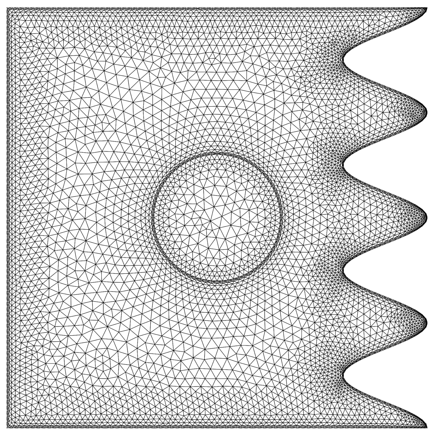
The impact of the mesh resolution on the accuracy of the solution was surveyed through a systematic mesh study. The solution was repeated by using several mesh sizes, and the average Nusselt number and maximum value of the streamline function were monitored. The domain elements and the corresponding values of Num and Ψmax are summarized in Table 3. A view of the pattern of the utilized mesh is depicted in Figure 2.
The most sensitive variable to the mesh size was the phase change region. Hence, the impact of various mesh cases on the phase change region was addressed in Figure 3. Figure 3 illustrates the Cr contours as an indication of phase change. As seen in Figure 3a–c the phase change interfaces are quite rough, and hence, the mesh could not capture the phase change region adequately. Moreover, the phase change region at the top and bottom of the enclosure is quite narrow and the meshes of Cases I, II, and III do not have enough resolution to properly compute the phase change in these locations. However, as seen in Figure 3d–f the corresponding meshes could capture the phase change regions smoothly. Thus, each of the meshes of Cases IV, V, and VI can be used for capturing the phase change region.
The results of Table 3 also indicate that the mesh size of case V could provide the results with one significant digit, which is adequate for graphical representation of the results and most of the engineering applications. Hence, as a trade between the computational cost and accuracy, case V was used for the computations.

3.3. Validations

The utilized numerical code was validated against the literature-works. The outcomes of the current method were compared with the case of nanofluid in a wavy wall cavity [49] and found in an agreement. Moreover, the results were also compared with the literature studies of Kahveci [52], and the experimental works of Corvaro and Paroncini [53], and the outcomes were almost identical. The maximum deviation between the results obtained in the current model and the results of Kahveci [52] is 0.092% for Ra = 105 and ϕ = 0.15.

4. Simulation Results

In this work, the dimensionless parameters are the Rayleigh number, Ra, the Prandtl number, Pr, the dimensionless rotational velocity, ω, which can be positive or negative, depending on the direction of clockwise and anticlockwise rotation, the heat capacity ratio, Rc, the thermal conductivity ratio Rk, the problem geometrical aspect ratio, R, the NEPCM volume fraction, ϕ, the fusion temperature, Tm, and the Stefan number, Ste.
The Prandtl number and Rayleigh number are fixed at 6.2 and 106, respectively. In addition, the numerical simulations are conducted for the following parameters: geometrical aspect ratio 0.1 ≤ R ≤ 0.2, dimensionless rotational velocity −1000 ≤ ω ≤ 1000, heat capacity ratios 1 ≤ Rc ≤ 100, thermal conductivity ratios 1 ≤ Rk ≤ 100, the NEPCM volume fraction ϕ = 0, 1.68, 3.36%, dimensionless fusion temperature 0.05 ≤ Tm ≤ 0.95, Stefan number 0.2 ≤ Ste ≤ ∞. The amplitude of the hot wall wave is also fixed at A = 0.1. The number of oscillations is in the range of 0 ≤ N ≤ 4. According to these ranges of dimensionless parameters, the values obtained by the Richardson number are Ri = for ω = 0, 3875 ≤ Ri ≤ 62,000 for │ω│ = 500, and 968.75 ≤ Ri ≤ 15,500 when │ω│ = 1000.
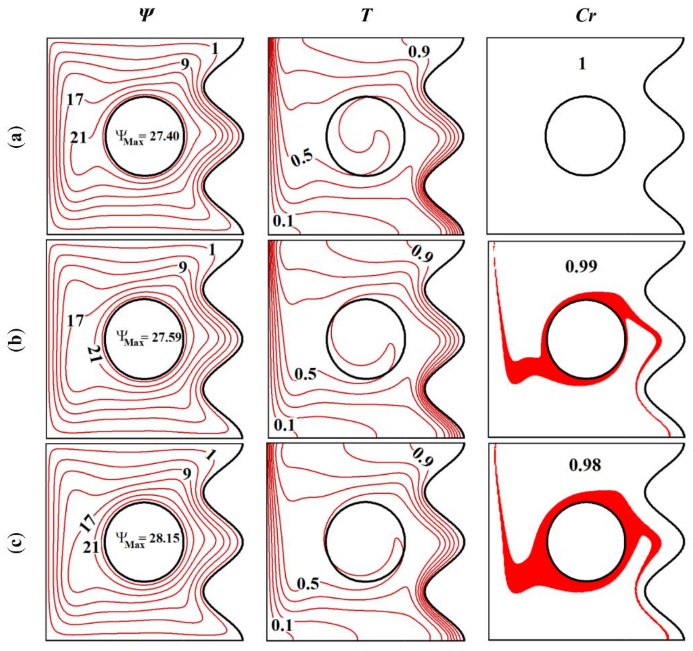
Figure 4, Figure 5, Figure 6, Figure 7 and Figure 8 illustrate, respectively, the effects of the rotational velocity of the inner cylinder ω, the fusion temperature of the NEPCM core Tm, the NEPCM volume fraction ϕ, the heat capacity ratio Rc and the thermal conductivity ratio Rk between the cylinder and the base liquid, and the cylinder radius R on the streamlines, the isotherms and the heat capacity ratio Cr contours in the cavity. In general, the flow is characterized by a counterclockwise vortex surrounding the inner cylinder. This is due to the convective effects resulting from the density difference between the hot fluid near the wavy wall and the cold one near the left wall. In fact, the heated fluid near the left wall moves upwards due to the buoyancy effects, and gets replaced by the cold fluid incoming from the region near the cold, which results in the counterclockwise circulation observed in the figure. In the vicinity of the wavy walls, the streamlines mimic the wall undulation and concentrate near the wall troughs due to the dominance of the conductive effects in that zone. The isothermal contours are vertical near the left wall, then move horizontally in the channel center as heat and finally reach the wavy wall and follow its undulated shape, as the hot fluid is ascending near the bottom of the right wall and descending near the left one while heat is being transferred from the hot fluid zone to the cold one. The isothermal contours are concentrated near the two walls. As for the Cr contours, the red zones indicate the region in which the core of the NEPCM particles. This is an indicator of the contribution of the NEPCM particles to the overall heat transfer by the latent heat of the core melting, as this contribution depends directly on the number of particles crossing the phase change zone. It can be seen that the phase change mainly occurs around the inner cylinder, i.e., in the same zone where the isotherm corresponding to T = 0.5 is present. This is due to the fact that the PCM being considered has a fusion temperature Tm = 0.5, which means that the PCM undergoes a phase change when its temperature is in the vicinity of 0.5. The red color in the Cr contours corresponds thus to the zone of the isotherm T = 0.5.
Figure 4 shows that changing the angular velocity ω of the cylinder affects the flow patterns. When the cylinder is rotating, the fluid in its vicinity moves following the rotation direction. It is evident that the flow intensity is increased when the cylinder is moving in the counterclockwise (CCW) rotation (ω > 0), as the forced and free convection are acting in the same direction. When the motion of the cylinder is in the clockwise (CW) direction, additional vortices are created in the space between the cylinder and the cavity walls due to the disturbance of the flow resulting from the opposition between the natural convection and the cylinder rotation directions. In other words, when the cylinder is rotating CW, the natural and forces convections act as opposed to each other, which results in a disturbed and slowed down flow circulation. On the other hand, when the cylinder rotates CCW, the forced convection adds to the effect of the natural one, and the flow circulation is enhanced. This is in accordance with previous research [43]. The isothermal contours follow the variation in the streamlines and are mainly affected when the cylinder is acting in the CW direction (ω > 0), especially in the area between the cylinder and the wavy wall. In fact, the shape of the isotherms does not vary significantly when the cylinder is rotating CCW, as the fluid keeps moving in the direction of free convection. In that case, the zone of phase change increases in size mainly around the cylinder, as indicated by the Cr contours.
The fusion temperature Tm has a slight effect on the flow patterns in the cavity but greatly affects the Cr contours, as indicated in Figure 5. Indeed, phase change in the NEPCM core occurs when the surrounding temperature is close to Tm. As a result, the red zone in the Cr coincides with the region around the isotherm corresponding to Tm. For this reason, the phase change is limited to the zone neighboring the left cold wall when Tm = 0.1, while it is limited to the vicinity of the hot wavy wall when Tm = 0.9. The phase change zone is at its largest for Tm = 0.5, as it occupies the region surrounding the inner cylinder and reaches the two side walls of the cavity.
A similar aspect can be seen for the effect of the volume fraction ϕ of the NEPCM particles in Figure 6. When ϕ = 0, the fluid is pure, and there are no NEPCM particles in the fluid to undergo a phase change. As ϕ is raised, the number of NEPCM particles experiencing melting increases, and correspondingly, the phase change zone increases in size. Moreover, a slight increase in the flow circulation is observed when ϕ is increased, indicating a contribution from the phase change heat transfer occurring at the NEPCM core to the overall convective effects.
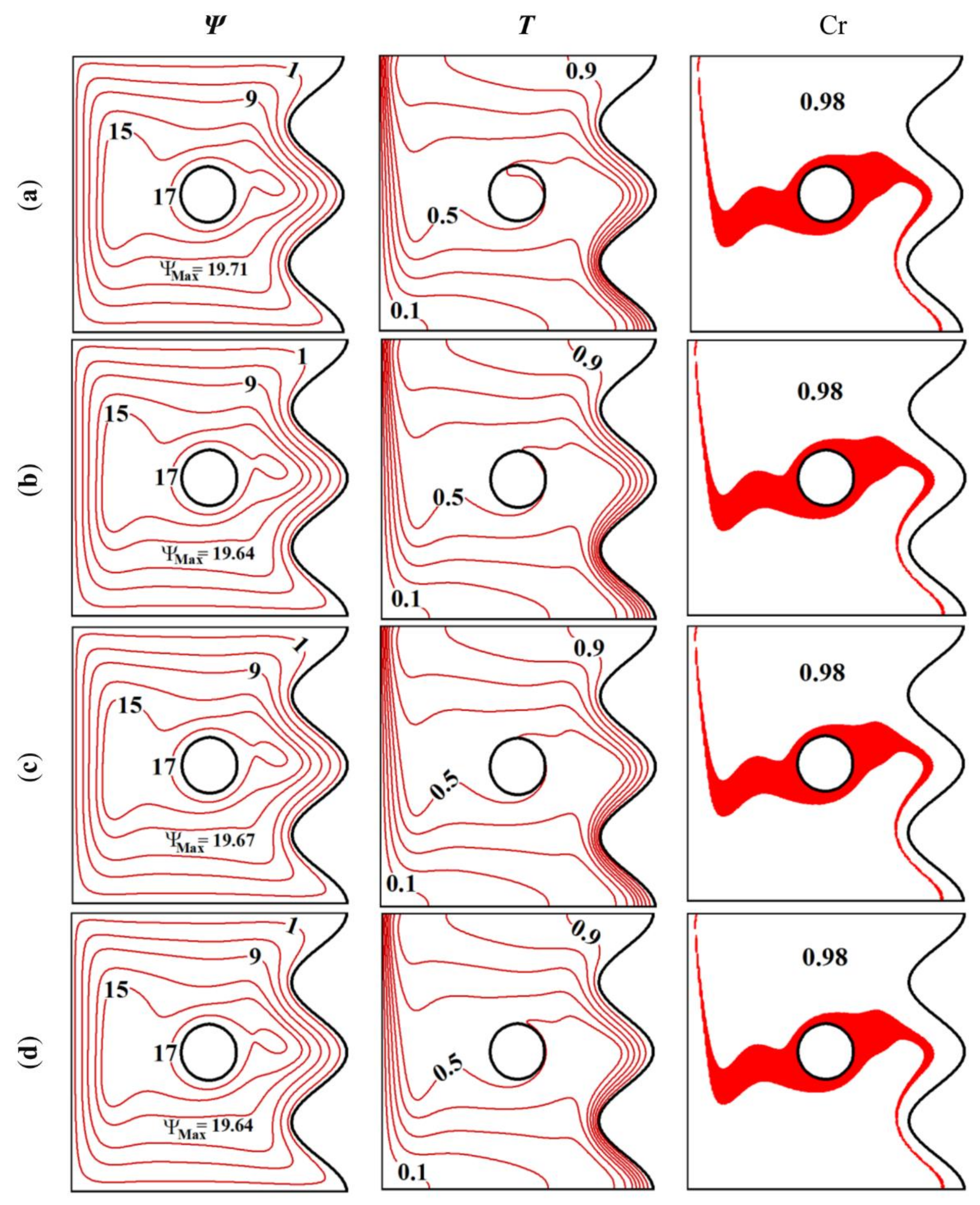
Looking at Figure 7 suggests that the two parameters Rc and Rk have very limited effects on the flow patterns and the temperature distribution in the cavity. This can be attributed to the fact that changing the heat capacity or the thermal conductivity of the inner cylinder induce only local effects limited to the region near the cylinder, which are very limited compared to the flow intensity in the whole cavity and to the convective heat transfer occurring between the hot wall near the wavy wall and the cold fluid near the left wall.
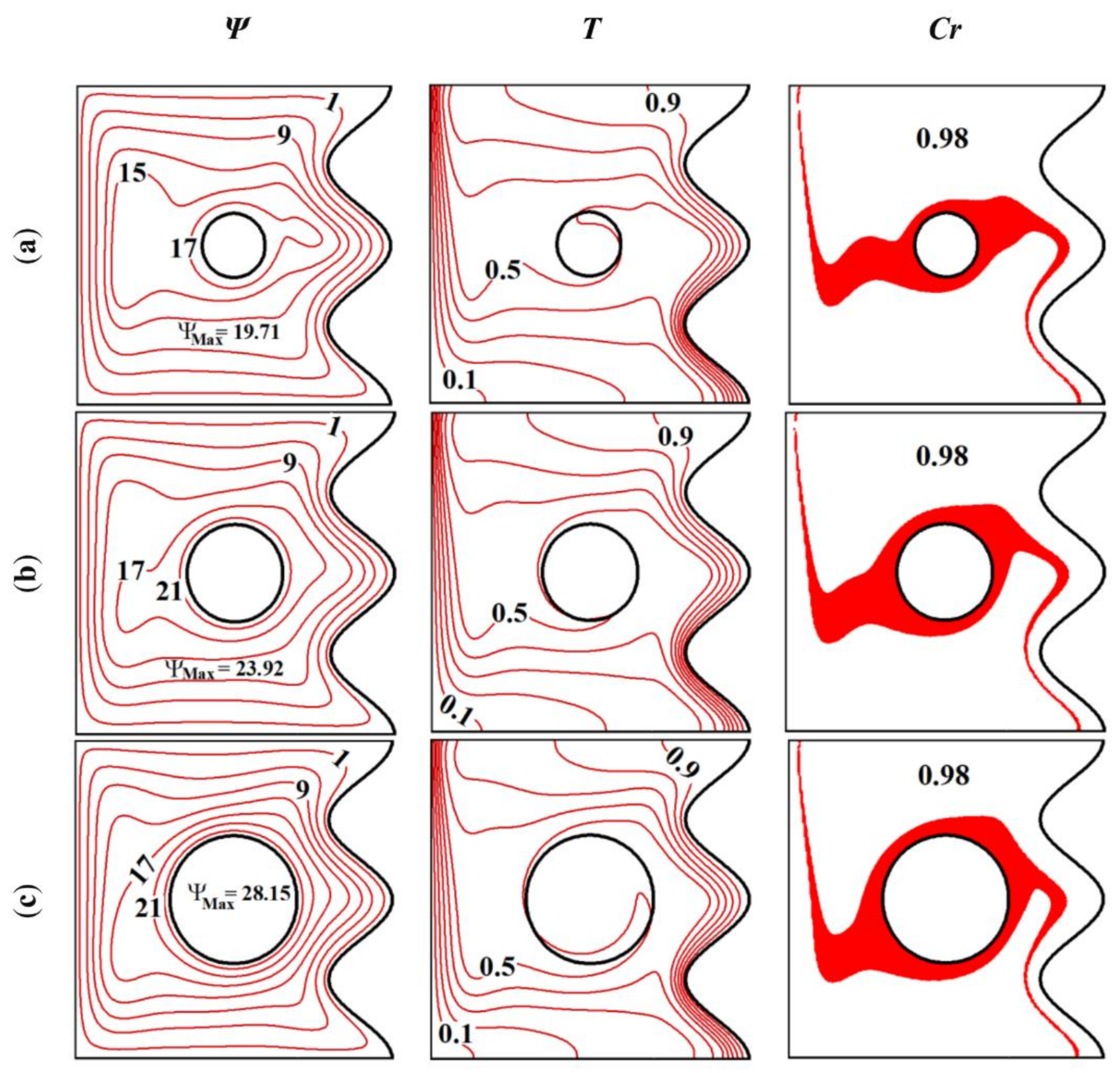
Increasing the size of the cylinder reduces the space in which the fluid is flowing, as illustrated in Figure 8. The streamlines are more concentrated for a larger cylinder size. However, no significant change appears in the flow patterns and the temperature distribution near the cavity walls. The effects of the size of the inner cylinder, thus, are localized in its vicinity as indicated by the change in the streamlines around the cylinder. Nonetheless, the reduction in the space surrounding the cylinder when R is increased still slightly hinders the convective effects. For the value Tm = 0.5 used in this figure, the change in the Cr contours is also near the cylinder. In fact, in the three considered cases, the red zone is always surrounding the cylinder, even when its radius is changed.
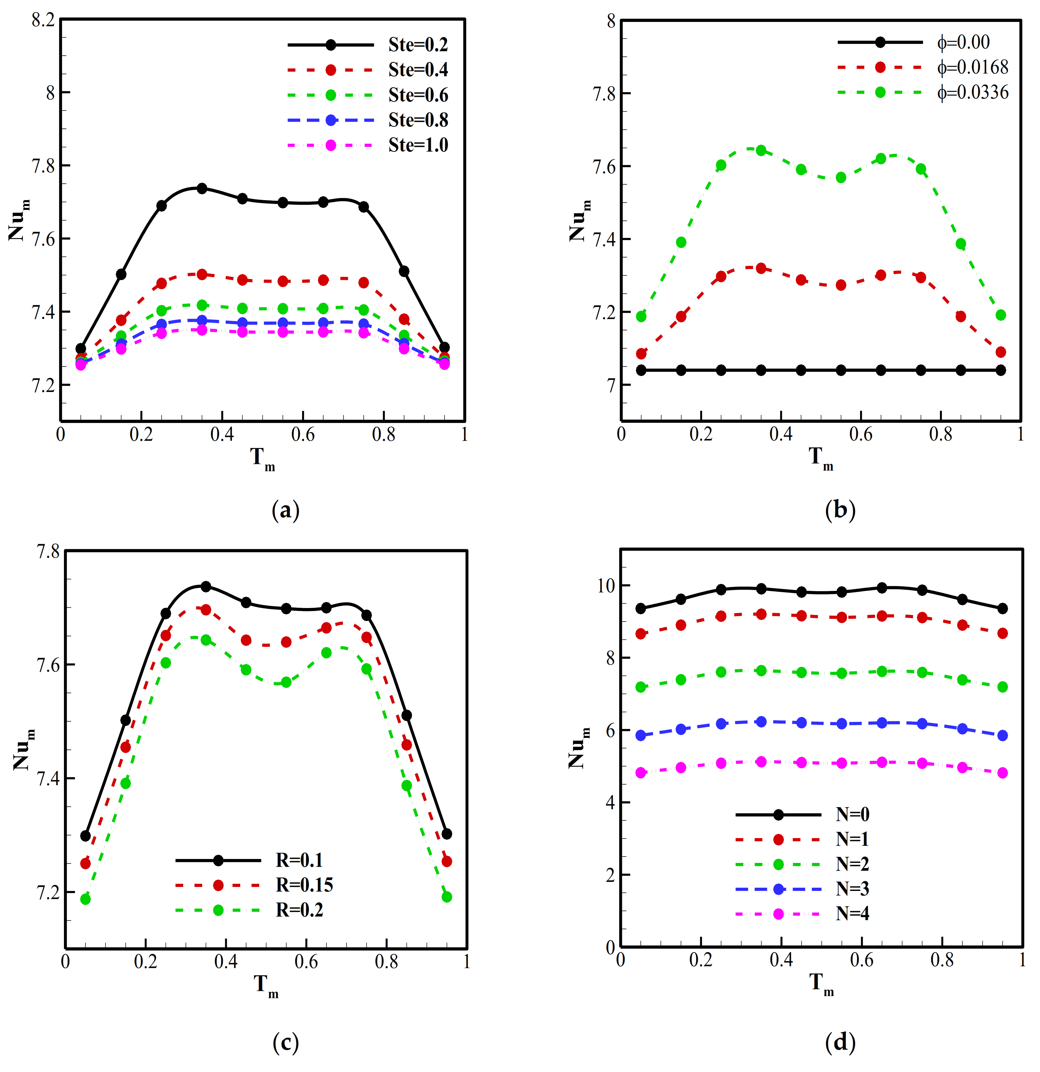
Figure 9a depicts the variation of the mean Nusselt number Num as a function of Tm for various values of Stefan number Ste. First, it can be seen that, for all the values of Ste, Num is minimum when the value of Tm is close to 0 or 1, i.e., when the fusion temperature of the NEPCM core is close to the temperature of the hot wall or to that of the cold wall. This is related to the dependence of the phase change zone on the value of Tm and on the corresponding isotherm, as discussed earlier. When Tm = 0 and Tm = 1, the phase change zone is limited to the region close to the cold wall or the hot wall only. As the contribution of the NEPCM to the heat transfer depends on the number of particles passing through the phase change zone, such contribution decreases when this zone is limited, and Num is reduced. The heat transfer is optimal when Tm is in the range [0.25, 0.75]. In addition, it is shown that higher values of Num are obtained when Ste is decreased. Indeed, Ste is inversely proportional to the latent heat of the NEPCM core. A high value of Ste diminishes the contribution of NEPCM to the heat transfer by undergoing a phase change, which translates into the reduction of Num. Overall, the results of Figure 9 indicate that the role played by the NEPCM particles in heat transfer enhancement is non-negligible.
The variation of Num as a function of Tm for different values of ϕ is plotted in Figure 9b. It is clear that using a higher value of ϕ increases Num for all the values of Tm. In fact, dispersing more NEPCM particles raises their thermal involvement by means of phase change heat, which enhances heat transfer. Nonetheless, this enhancement is less pronounced when Tm is close to 0 or 1, when the contribution of the NECPM particle to heat transfer is diminished, as seen in Figure 9a.
Figure 9c shows the impact of R on the variation of Num as a function of Tm. It is clear that raising R reduces Num and that heat transfer is maximized for R = 0.1. Indeed, using a larger cylinder limits the zone in which the fluid can flow and inhibits convective effects.
The effect of the number of oscillations of the wavy wall N on the variation of Num as a function of Tm is illustrated in Figure 9d. It is clear that Num increases when N is reduced and is maximum in the case of a flat wall (N = 0). In fact, when the wall is undulated, the streamlines mimic the wall shape and present higher concentration near the wall troughs, while flow separation appears near the crest and in the right upper corner. This led to the emergence of a thermal boundary layer in those regions as seen in Figure 4. Consequently, the convective effects are diminished. This observation is in agreement with previous findings [44]. In the case of a flat wall, this phenomenon is absent, and the heat transfer is maximized, while using an undulated wall and increasing the number of oscillations further diminishes heat transfer.
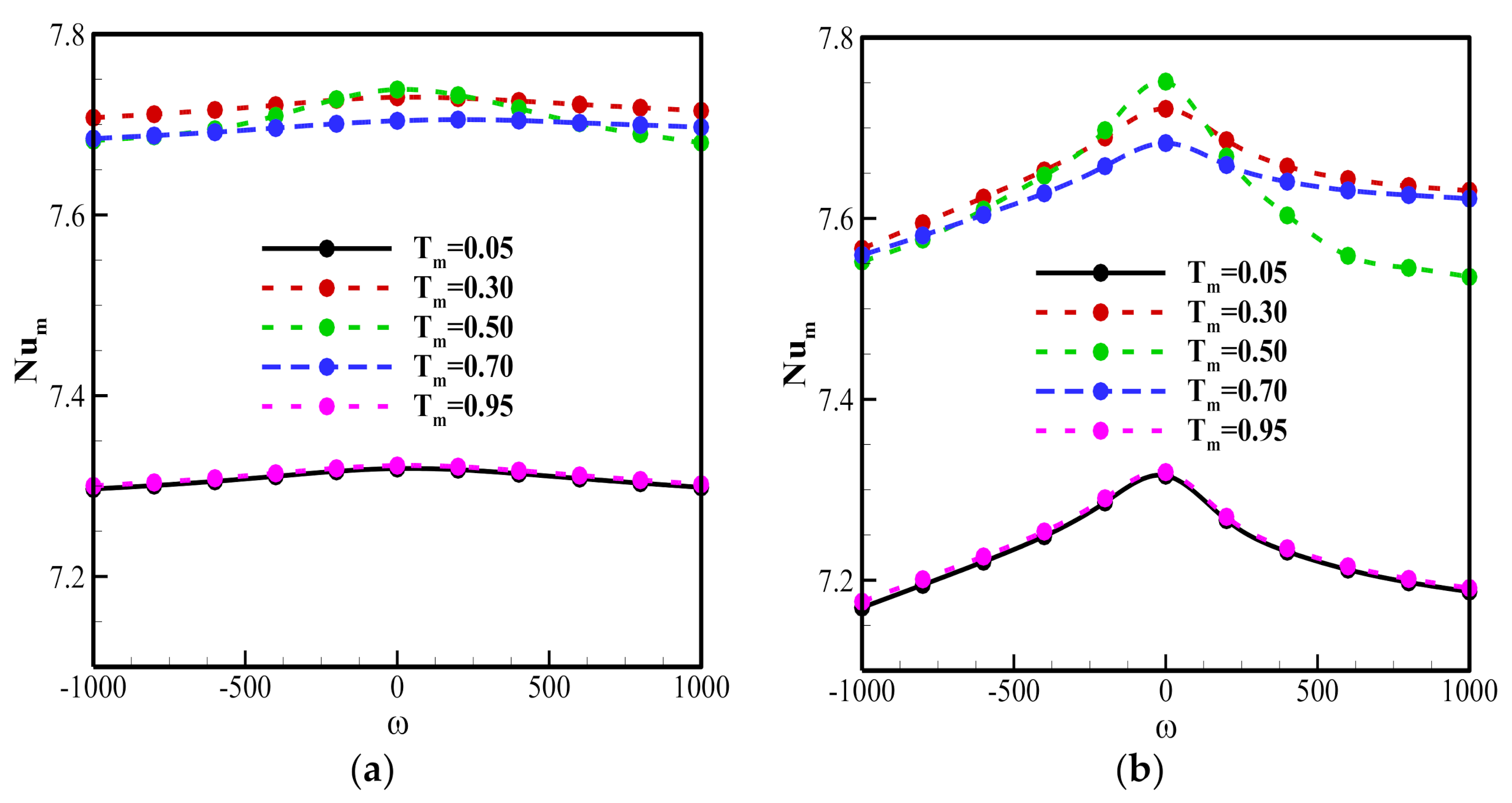
The variation of Num as a function of Tm is depicted in Figure 10 for different values of ω and for two values of R. First, it can be seen that Num is slightly higher when ω = 0, i.e., when the inner cylinder is not rotating. This result is related to the flow patterns observed in Figure 4, where the thermal contact between the fluid and the side walls is higher for a still cylinder and to the appearance of additional vortices to the right and the left of the cylinder in that case. Moreover, it is shown that the heat transfer is inhibited for Tm = 0 and Tm = 1 compared to the other cases, due to the reduction of the phase change zone corresponding to these zones, as discussed earlier.
The variation of Num as a function of Ste is plotted for various values of Rk and Rc in Figure 11a,b, respectively. It is shown that both Rk and Rc have limited effects on the heat transfer rate, as increasing those parameters slightly raises the value of Num due to the relative increase of the thermal conductivity and the heat capacity of the cylinder. Moreover, Num decreases with Ste for all the values of Rk and Rc due to the reduction of latent heat contribution.

5. Conclusions

The conjugate phase change heat transfer of NEPCM-suspensions was examined in a wavy wall cavity theoretically. The phase change nanoparticles circulate in the enclosure, and they transport a notable amount of heat by their latent heat of fusion. The heat transfer advantage of using NEPCM particles was discussed in detail. A cavity with a wavy heated wall and containing a rotating cylinder was simulated. The nanofluid inside the cavity is based on NEPCM particles. The effects of various parameters such as the NEPCM volume fraction, the PCM fusion temperature, the radius of the cylinder, its heat capacity and its thermal conductivity, the cylinder velocity, and the number of undulations of the wavy wall were considered. The results were presented and discussed in the form of phase change maps, isotherms, streamlines, and Nusselt number curves. A summary of the results can be presented as follows:
  • Dispersing NEPCM particles in the base fluid enhances heat transfer. This enhancement increases with the volume fraction of the nanoparticles. A 10% increase in heat transfer can be observed when a 3.36% volume particle is used compared to the base fluid. The latent heat involved when the PCM undergoes phase change contributes to the overall heat transfer.
  • The fusion temperature Tm of the NEPCM core affects the contribution of the nanoparticles to the overall heat transfer. When Tm is close to the temperature of the hot wall or the cold wall, the zone in which the core, undergoes the phase-change, is reduced. The number of NEPCM particles experiencing melting decreases and heat transfer is diminished.
  • Using a larger cylinder inhibits heat transfer by reducing the space in which the fluid can flow and, consequently, the convective effects. Heat transfer is also slightly higher when the cylinder rotational velocity is close to zero. On the other hand, the thermal conductivity and the heat capacity of the cylinder presented by the parameters Rk and Rc seem to have little impact on heat transfer.
  • Heat transfer is improved when the number of undulations N of the wavy wall is reduced and reaches its maximum when the hot wall is flat. This is due to the presence of a thermal boundary layer as well as the available space between the cylinder and the surrounding fluid when N is increased, hindering heat transfer.

Author Contributions

Conceptualization, S.A.M.M. and M.G.; methodology, S.A.M.M., K.R., L.S.G., A.H., O.Y. and M.G.; software, S.A.M.M., L.S.G. and M.G.; validation, S.A.M.M. and M.G.; formal analysis, S.A.M.M., K.R., A.H. and O.Y.; investigation, S.A.M.M., K.R., A.H., O.Y. and M.E.K.; resources, K.R. and O.Y.; writing—original draft preparation, S.A.M.M., K.R., L.S.G., A.H., O.Y., M.E.K. and M.G.; writing—review and editing, S.A.M.M., K.R., L.S.G., A.H., O.Y., M.E.K. and M.G.; visualization, S.A.M.M., L.S.G.; supervision, M.G.; funding acquisition, K.R., O.Y. and M.G. All authors have read and agreed to the published version of the manuscript.

Funding

This research received no external funding.

Institutional Review Board Statement

Not applicable.

Informed Consent Statement

Not applicable.

Data Availability Statement

The data will be available on request.

Conflicts of Interest

The authors declare no conflict of interest.

Glossary

Latin letters
Athe hot wall wave amplitude
Cthe specific heat (kJ/kg.K)
Crthe ratio of the heat capacity of the nanoliquid to the base liquid
fthe normalized fusion function
gthe gravity constant (m/s2)
Hthe enclosure height (m)
kthermal conductivity coefficient (W/m.K)
Nthe number of oscillations
NuNusselt number
pthe suspension pressure field (Pa)
Pnon-dimensional suspension pressure field
PrPrandtl number
Rthe cylinder radius
RaRayleigh number
Rcthe heat capacity ratio of the cylinder to the base liquid
Rkthe thermal conductivity ratio of the cylinder to the base liquid
RiRichardson number
SteStefan number
Tthe temperature (°C)
Tmthe dimensionless fusion temperature
TMrthe melting temperature range (°C)
ux axis velocity component (m/s)
UX axis non-dimensional velocity component
vy axis velocity component (m/s)
VY axis non-dimensional velocity component
xx-Cartesian coordinate (m)
Xdimensionless X-Cartesian coordinate
yy-Cartesian coordinate (m)
Ydimensionless Y-Cartesian coordinate
Greek symbols
αthe thermal diffusivity (m2/s)
βthe volumetric thermal expansion coefficient(1/K)
δTthe non-dimensional phase change band
εthe non-dimensional ratio of the heat capacity
μthe dynamic viscosity (kg s/m)
ζthe core-shell weight ratio of the particles
ρdensity (kg/m3)
ϕthe NEPCM volume fraction
Ψthe stream function
ωcylinder rotational speed
Subscript
blthe base liquid
cthe cold wall
cthe PCM core
cythe cylinder
hthe hot wall
llocal
mmean
nathe NEPCM nanoparticles
nlthe nanoliquid
rthe dimensionless ratios
sthe shell of NEPCM particle
*normalized form of the parameters

References

  1. Peterson, G.P.; Li, C.H. Heat and Mass Transfer in Fluids with Nanoparticle Suspensions. Adv. Heat Transf. 2006, 39, 257–376. [Google Scholar] [CrossRef]
  2. Jang, S.P.; Choi, S.U.S. Effects of Various Parameters on Nanofluid Thermal Conductivity. J. Heat Transf. 2007, 129, 617–623. [Google Scholar] [CrossRef]
  3. Wen, D.; Ding, Y. Natural Convective Heat Transfer of Suspensions of Titanium Dioxide Nanoparticles (Nanofluids). IEEE Trans. Nanotechnol. 2006, 5, 220–227. [Google Scholar]
  4. Sheikholeslami, M.; Mehryan, S.A.M.; Shafee, A.; Sheremet, M.A. Variable magnetic forces impact on magnetizable hybrid nanofluid heat transfer through a circular cavity. J. Mol. Liquids 2019, 277, 388–396. [Google Scholar] [CrossRef]
  5. Reza-E-Rabbi, S.; Ahmmed, S.F.; Arifuzzaman, S.; Sarkar, T.; Khan, M.S. Computational modelling of multiphase fluid flow behaviour over a stretching sheet in the presence of nanoparticles. Eng. Sci. Technol. Int. J. 2020, 23, 605–617. [Google Scholar] [CrossRef]
  6. Wakif, A.; Chamkha, A.; Thumma, T.; Animasaun, I.; Sehaqui, R. Thermal radiation and surface roughness effects on the thermo-magneto-hydrodynamic stability of alumina–copper oxide hybrid nanofluids utilizing the generalized Buongiorno’s nanofluid model. J. Therm. Anal. Calorim. 2020, 1–20. [Google Scholar] [CrossRef]
  7. Sivasankaran, S.; Alsabery, A.I.; Hashim, I. Internal heat generation effect on transient natural convection in a nanofluid-saturated local thermal non-equilibrium porous inclined cavity. Phys. A Stat. Mech. Appl. 2018, 509, 275–293. [Google Scholar] [CrossRef]
  8. Kuznetsov, A.V.; Nield, D.A. Effect of Local Thermal Non-equilibrium on the Onset of Convection in a Porous Medium Layer Saturated by a Nanofluid. Transp. Porous Media 2009, 83, 425–436. [Google Scholar] [CrossRef]
  9. Bhadauria, B.S.; Agarwal, S. Convective Transport in a Nanofluid Saturated Porous Layer With Thermal Non Equilibrium Model. Transp. Porous Media 2011, 88, 107–131. [Google Scholar] [CrossRef]
  10. Sun, Q.; Pop, I. Free convection in a triangle cavity filled with a porous medium saturated with nanofluids with flush mounted heater on the wall. Int. J. Therm. Sci. 2011, 50, 2141–2153. [Google Scholar] [CrossRef]
  11. Chamkha, A.J.; Ismael, M.A. Conjugate heat transfer in a porous cavity filled with nanofluids and heated by a triangular thick wall. Int. J. Therm. Sci. 2013, 67, 135–151. [Google Scholar] [CrossRef]
  12. Sheikholeslami, M. CuO-water nanofluid flow due to magnetic field inside a porous media considering Brownian motion. J. Mol. Liquids 2018, 249, 921–929. [Google Scholar] [CrossRef]
  13. Xuan, Y.; LI, Q. Investigation on convective heat transfer and flow features of nanofluids. J. Heat Transf. 2003, 125, 151–155. [Google Scholar] [CrossRef] [Green Version]
  14. Wen, D.; Ding, Y. Experimental investigation into convective heat transfer of nanofluids at the entrance region under laminar flow conditions. Int. J. Heat Mass Transf. 2004, 47, 5181–5188. [Google Scholar] [CrossRef]
  15. Hwang, K.S.; Jang, S.P.; Choi, S.U.S. Flow and convective heat transfer characteristics of water-based Al2O3 nanofluids in fully developed laminar flow regime. Int. J. Heat Mass Transf. 2009, 52, 193–199. [Google Scholar] [CrossRef]
  16. Sajid, M.U.; Ali, H.M. Recent advances in application of nanofluids in heat transfer devices: A critical review. Renew. Sustain. Energy Rev. 2019, 103, 556–592. [Google Scholar] [CrossRef]
  17. Kant, K.; Shukla, A.; Sharma, A. Advancement in phase change materials for thermal energy storage applications. Solar Energy Mater. Solar Cells 2017, 172, 82–92. [Google Scholar] [CrossRef]
  18. Khan, R.J.; Bhuiyan, M.Z.H.; Ahmed, D.H. Investigation of heat transfer of a building wall in the presence of phase change material (PCM). Energy Built Environ. 2020, 1, 199–206. [Google Scholar] [CrossRef]
  19. Hu, W.; Song, M.; Jiang, Y.; Yao, Y.; Gao, Y. A modeling study on the heat storage and release characteristics of a phase change material based double-spiral coiled heat exchanger in an air source heat pump for defrosting. Appl. Energy 2019, 236, 877–892. [Google Scholar] [CrossRef]
  20. Emam, M.; Ookawara, S.; Ahmed, M. Thermal management of electronic devices and concentrator photovoltaic systems using phase change material heat sinks: Experimental investigations. Renew. Energy 2019, 141, 322–339. [Google Scholar] [CrossRef]
  21. Isa, M.H.M.; Zhao, X.; Yoshino, H. Preliminary study of passive cooling strategy using a combination of PCM and copper foam to increase thermal heat storage in building facade. Sustainability 2010, 2, 2365–2381. [Google Scholar] [CrossRef] [Green Version]
  22. Baek, S.; Kim, S. Determination of optimum hot-water temperatures for PCM radiant floor-heating systems based on the wet construction method. Sustainability 2018, 10, 4004. [Google Scholar] [CrossRef] [Green Version]
  23. González-Peña, D.; Alonso-deMiguel, I.; Díez-Mediavilla, M.; Alonso-Tristán, C. Experimental analysis of a novel PV/T panel with PCM and heat pipes. Sustainability 2020, 12, 1710. [Google Scholar] [CrossRef] [Green Version]
  24. Zhao, C.Y.; Kim, T.; Lu, T.J.; Hodson, H.P. Thermal Transport in High Porosity Cellular Metal Foams. J. Thermophys. Heat Transf. 2004, 18, 309–317. [Google Scholar] [CrossRef]
  25. Calmidi, V.V.; Mahajan, R.L. Forced convection in high porosity metal foams. J. Heat Transf. 2000, 122, 557–565. [Google Scholar] [CrossRef]
  26. Zhao, C.Y.; Lu, T.J.; Hodson, H.P. Natural convection in metal foams with open cells. Int. J. Heat Mass Transf. 2005, 48, 2452–2463. [Google Scholar] [CrossRef]
  27. Zhao, C.Y.; Lu, W.; Tian, Y. Heat transfer enhancement for thermal energy storage using metal foams embedded within phase change materials (PCMs). Solar Energy 2010, 84, 1402–1412. [Google Scholar] [CrossRef] [Green Version]
  28. Siahpush, A.; O’Brien, J.; Crepeau, J. Phase change heat transfer enhancement using copper porous foam. ASME Trans. J. Heat Transf. 2008, 130, 082301–082311. [Google Scholar] [CrossRef]
  29. Zhu, Y.; Qin, Y.; Wei, C.; Liang, S.; Luo, X.; Wang, J.; Zhang, L. Nanoencapsulated phase change materials with polymer-SiO2 hybrid shell materials: Compositions, morphologies, and properties. Energy Convers. Manag. 2018, 164, 83–92. [Google Scholar] [CrossRef]
  30. Alva, G.; Huang, X.; Liu, L.; Fang, G. Synthesis and characterization of microencapsulated myristic acid–palmitic acid eutectic mixture as phase change material for thermal energy storage. Appl. Energy 2017, 203, 677–685. [Google Scholar] [CrossRef]
  31. Cao, L.; Tang, F.; Fang, G. Preparation and characteristics of microencapsulated palmitic acid with TiO2 shell as shape-stabilized thermal energy storage materials. Solar Energy Mater. Solar Cells 2014, 123, 183–188. [Google Scholar] [CrossRef]
  32. Zhao, L.; Wang, H.; Luo, J.; Liu, Y.; Song, G.; Tang, G. Fabrication and properties of microencapsulated n-octadecane with TiO2 shell as thermal energy storage materials. Solar Energy 2016, 127, 28–35. [Google Scholar] [CrossRef]
  33. Peng, J.; Cheng, Q. High-Performance Nanocomposites Inspired by Nature. Adv. Mater. 2017, 29. [Google Scholar] [CrossRef] [PubMed]
  34. Caruso, F.; Trau, D.; Möhwald, H.; Renneberg, R. Enzyme Encapsulation in Layer-by-Layer Engineered Polymer Multilayer Capsules. Langmuir 2000, 16, 1485–1488. [Google Scholar] [CrossRef]
  35. Shchukin, D.G.; Zheludkevich, M.; Yasakau, K.; Lamaka, S.; Ferreira, M.G.S.; Möhwald, H. Layer-by-Layer Assembled Nanocontainers for Self-Healing Corrosion Protection. Adv. Mater. 2006, 18, 1672–1678. [Google Scholar] [CrossRef]
  36. Soottitantawat, A.; Yoshii, H.; Furuta, T.; Ohkawara, M.; Linko, P. Microencapsulation by Spray Drying: Influence of Emulsion Size on the Retention of Volatile Compounds. J. Food Sci. 2003, 68, 2256–2262. [Google Scholar] [CrossRef]
  37. Su, J.-F.; Wang, L.-X.; Ren, L. Synthesis of polyurethane microPCMs containing n-octadecane by interfacial polycondensation: Influence of styrene-maleic anhydride as a surfactant. Colloids Surfaces A Physicochem. Eng. Asp. 2007, 299, 268–275. [Google Scholar] [CrossRef]
  38. Fang, G.; Li, H.; Yang, F.; Liu, X.; Wu, S. Preparation and characterization of nano-encapsulated n-tetradecane as phase change material for thermal energy storage. Chem. Eng. J. 2009, 153, 217–221. [Google Scholar] [CrossRef]
  39. Rodríguez-Cumplido, F.; Pabón-Gelves, E.; Chejne-Jana, F. Recent developments in the synthesis of microencapsulated and nanoencapsulated phase change materials. J. Energy Storage 2019, 24. [Google Scholar] [CrossRef]
  40. Huu-Quan, D.; Sheremet, M.; Kamel, M.S.; Izadi, M. Investigation of thermal-hydro dynamical behavior on nano-encapsulated PCM suspension: Effect of fin position, fractioning and aspect ratio. Chem. Eng. Process. Process. Intensif. 2020, 157, 108122. [Google Scholar] [CrossRef]
  41. Ouertatani, N.; Cheikh, N.B.; Beya, B.B.; Lili, T.; Campo, A. Mixed convection in a double lid-driven cubic cavity. Int. J. Therm. Sci. 2009, 48, 1265–1272. [Google Scholar] [CrossRef]
  42. Selimefendigil, F.; Öztop, H.F. Conjugate mixed convection of nanofluid in a cubic enclosure separated with a conductive plate and having an inner rotating cylinder. Int. J. Heat Mass Transf. 2019, 139, 1000–1017. [Google Scholar] [CrossRef]
  43. Chamkha, A.J.; Selimefendigil, F. MHD mixed convection of nanofluid due to an inner rotating cylinder in a 3D enclosure with a phase change material. Int. J. Numer. Methods Heat Fluid Flow 2019, 29, 3559–3583. [Google Scholar] [CrossRef]
  44. Alnajem, M.H.S.; Alsabery, A.I.; Hashim, I. Entropy generation and natural convection in a wavy-wall cavity filled with a nanofluid and containing an inner solid cylinder. IOP Conf. Series Mater. Sci. Eng. 2019, 518. [Google Scholar] [CrossRef]
  45. Alsabery, A.I.; Mohebbi, R.; Chamkha, A.J.; Hashim, I. Effect of local thermal non-equilibrium model on natural convection in a nanofluid-filled wavy-walled porous cavity containing inner solid cylinder. Chem. Eng. Sci. 2019, 201, 247–263. [Google Scholar] [CrossRef]
  46. Alsabery, A.I.; Sheremet, M.A.; Chamkha, A.J.; Hashim, I. Impact of nonhomogeneous nanofluid model on transient mixed convection in a double lid-driven wavy cavity involving solid circular cylinder. Int. J. Mech. Sci. 2019, 150, 637–655. [Google Scholar] [CrossRef]
  47. Sheremet, M.A.; Revnic, C.; Pop, I. Free convection in a porous wavy cavity filled with a nanofluid using Buongiorno’s mathematical model with thermal dispersion effect. Appl. Math. Comput. 2017, 299, 1–15. [Google Scholar] [CrossRef]
  48. Alsabery, A.I.; Tayebi, T.; Roslan, R.; Chamkha, A.J.; Hashim, I. Entropy Generation and Mixed Convection Flow Inside a Wavy-Walled Enclosure Containing a Rotating Solid Cylinder and a Heat Source. Entropy 2020, 22, 606. [Google Scholar] [CrossRef]
  49. Alsabery, A.I.; Ismael, M.A.; Chamkha, A.J.; Hashim, I. Numerical investigation of mixed convection and entropy generation in a wavy-walled cavity filled with nanofluid and involving a rotating cylinder. Entropy 2018, 20, 664. [Google Scholar] [CrossRef] [Green Version]
  50. Khan, M.S.; Zou, R.; Yu, A. Computational simulation of air-side heat transfer and pressure drop performance in staggered mannered twisted oval tube bundle operating in crossflow. Int. J. Therm. Sci. 2020, 106748. [Google Scholar]
  51. Hashim, I.; Alsabery, A.; Sheremet, M.A.; Chamkha, A. Numerical investigation of natural convection of Al2O3-water nanofluid in a wavy cavity with conductive inner block using Buongiorno’s two-phase model. Adv. Powder Technol. 2019, 30, 399–414. [Google Scholar] [CrossRef]
  52. Kahveci, K. Buoyancy driven heat transfer of nanofluids in a tilted enclosure. J. Heat Transf. 2010, 132. [Google Scholar] [CrossRef]
  53. Corvaro, F.; Paroncini, M. An experimental study of natural convection in a differentially heated cavity through a 2D-PIV system. Int. J. Heat Mass Transf. 2009, 52, 355–365. [Google Scholar] [CrossRef]
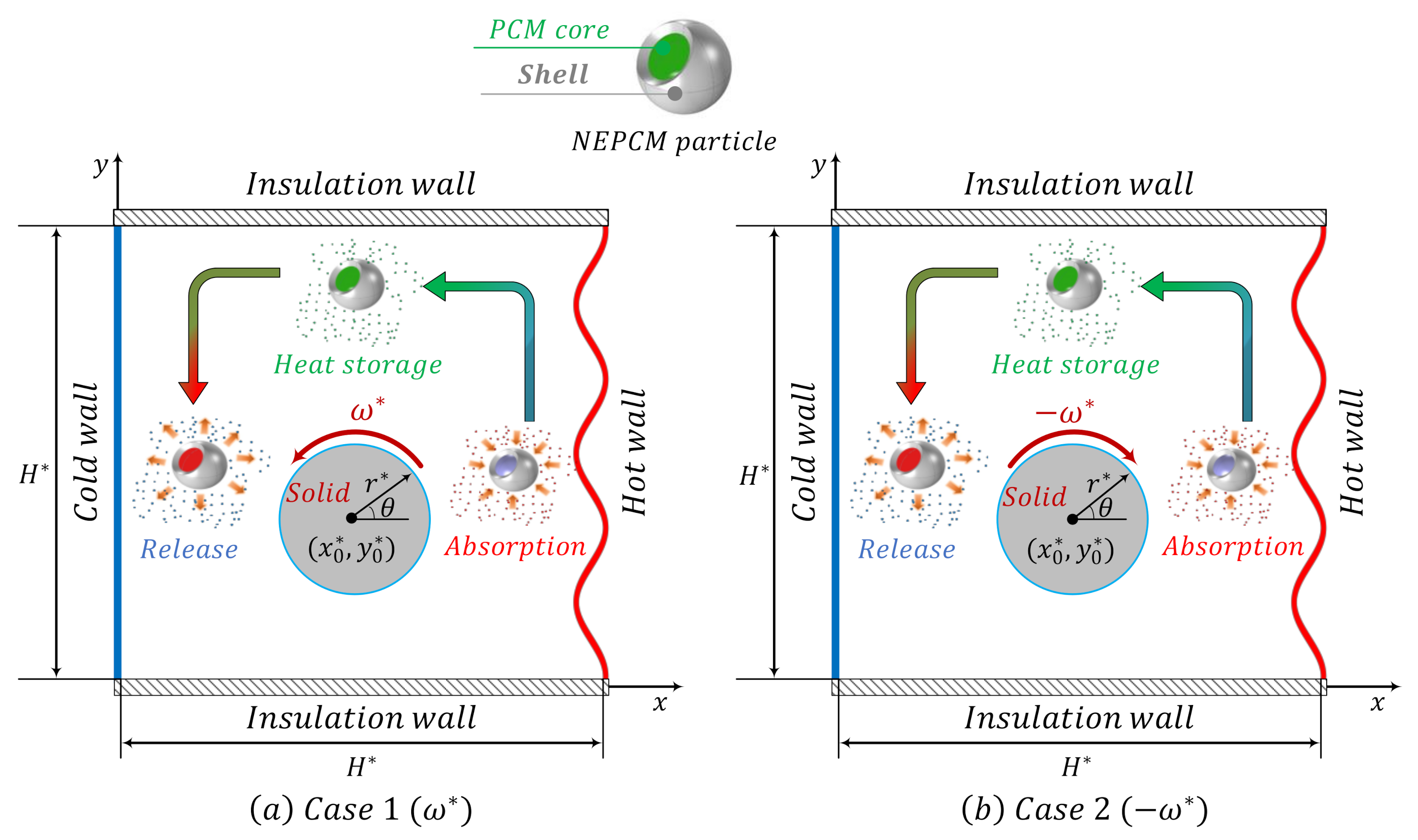
Figure 1. Schematic configuration.
Sustainability 13 02590 g001
Figure 2. A view of the pattern of utilized mesh.
Sustainability 13 02590 g002
Figure 3. The effect of grid size on the Cr contours when, R = 0.2, N = 2, Rk = Rc = 1, ω = 1000, Tm = 0.5, Ste = 0.2 and ϕ = 3.36%; for grid sizes: (a) Case I, (b) Case II, (c) Case III, (d) Case IV, (e) Case V, (f) Case VI.
Sustainability 13 02590 g003
Figure 4. The streamlines (left), isotherms (center) and Cr contours (right) when R = 0.2, ϕ = 3.36%, Tm = 0.5, Rc = 1, Rk = 1 and Ste = 0.2; for (a) ω = 1000, (b) ω = 500, (c) ω = 0 (d) ω = −500 (e) ω = −1000.
Sustainability 13 02590 g004
Figure 5. The streamlines (left), isotherm contours (center) and Cr contours (right) when R = 0.2, ϕ = 3.36%, ω = 1000, Rc = 1, Rk = 1 and Ste = 0.2; for (a) Tm = 0.1, (b) Tm = 0.5, (c) Tm = 0.9.
Sustainability 13 02590 g005
Figure 6. The streamlines (left), isotherm contours (center) and Cr contours (right) when R = 0.2, Tm = 0.5, ω = 1000, Rc = 1, Rk = 1 and Ste = 0.2; for (a) ϕ = 0, (b) ϕ = 0.0168, (c) ϕ = 0.0336.
Sustainability 13 02590 g006
Figure 7. The streamlines (left), isotherm contours (center) and Cr contours (right) when R = 0.1, Tm = 0.5, ϕ = 3.36%, ω = 1000 and Ste = 0.2; for (a) Rc = 1, Rk = 1, (b) Rc = 1, Rk = 10, (c) Rc = 10, Rk = 1, (d) Rc = 10, Rk = 10.
Sustainability 13 02590 g007
Figure 8. The streamlines (left), isotherms (center) and Cr contours (right) when Tm = 0.5, ω = 1000, ϕ = 3.36%, N = 2, Rc = 1, Rk = 1 and Ste = 0.2; for (a) R = 0.1, (b) R = 0.15, (c) R = 0.2.
Sustainability 13 02590 g008
Figure 9. Dependency of the Num on the fusion temperature when ω = 1000, Rc = 1, and Rk = 1 for: (a) different values of Ste and ϕ = 3.36%, R = 0.1, N = 2; (b) different values of volume fraction and Ste = 0.2, R = 0.2, N = 2; (c) different values of R and ϕ = 3.36%, Ste = 0.2, N = 2; (d) different values of N and ϕ = 3.36%, R = 0.1, Ste = 0.2.
Sustainability 13 02590 g009
Figure 10. Dependency of the Num on the rotational velocity for different values of Tm, when ϕ = 3.36%, Ste = 0.2, N = 2, Rc = 1, Rk = 1; for: (a) R = 0.1′ (b) R = 0.2.
Sustainability 13 02590 g010
Figure 11. Dependency of the Num on Stefan number when ω = 1000, ϕ = 3.36%, Tm = 0.5, N = 2 and R = 0.2: (a) different values of Rk and Rc = 1; (b) different values of Rc and Rk = 1.
Sustainability 13 02590 g011
Table 1. Thermophysical properties of the shell and core of the NEPCMs and the base fluid [27,28].
Materialβ (K−1)C (kJ/kg K)k (W/m K)ρ (kg/m3)
Polyurethane: shell17.28 × 10−51.3177 786
Nonadecane: core 2.037 721
Water: base fluid21 × 10−54.1790.613997.1
Table 2. The thermal conductivity and dynamic viscosity ratios of the nanoliquid to the base liquid.
Volume Fraction of the Nano-Additives (%)0.01.683.36
k n l / k b 11.11.2
μ n l / μ b 11.221.42
Table 3. The effect of grid size on the average Nusselt number on the hot wall and absolute maximum stream function for the case of Ra = 106, R = 0.2, N = 2, Rk = Rc = 1, ω = 1000, Tm = 0.5, Ste = 0.2 and ϕ = 3.36%.
Domain ElementsCase I
(14,010)
Case II
(23,388)
Case III
(30,816)
Case IV
(56,394)
Case V
(68,781)
Case VI
(80,496)
Num7.57447.53457.53417.53287.53557.5360
Ψmax28.24028.23228.21628.15828.14626.160
Publisher’s Note: MDPI stays neutral with regard to jurisdictional claims in published maps and institutional affiliations.