Article

Structural Performance and Reinforcement Improvement of Structural Walls Using Strain-Hardening Cementitious Composites

1
Department of Architectural Engineering, Chosun University, Gwangju 61452, Korea
2
Department of Architectural Engineering, Kyung Hee University, Yongin 17104, Korea
*
Author to whom correspondence should be addressed.
Sustainability 2021, 13(7), 3607; https://doi.org/10.3390/su13073607
Submission received: 6 March 2021 / Revised: 18 March 2021 / Accepted: 19 March 2021 / Published: 24 March 2021

Abstract

:
Reinforced concrete (RC) shear walls are effective in improving lateral stiffness and load-carrying capacity under earthquake and wind loads. According to the level of seismic design, however, the spacing of reinforcing steel bars should be very narrow and complicated, with tight spacing of tied bars, as is the case with seismically special RC shear wall design. The purpose of this study was to investigate the applicability of strain-hardening cementitious composites (SHCCs) in structural walls in order to improve structural performance as well as the complications with reinforcement details. The SHCC was mixed, and mechanical tests showed that the SHCC exhibited high ductile tensile strains above 2.0%, while sustaining the tensile stress after cracks and developing multiple microcracks, avoiding crack localizations. Six specimens of RC and reinforced SHCC structural walls were designed and manufactured with varying reinforcement details, and experiments on wall specimens were carried out under transverse wall-loading tests. These experiments demonstrated that the use of SHCC in structural walls, despite minimum use of reinforcement ratios, showed improved responses to minimize damage and failure caused by localized cracks under bending and shear to compared with the use of normal reinforcement ratios in RC walls.

1. Introduction

From the late twentieth century, newly projected constructions of high-rise buildings gradually expanded from the West to Asian countries, accompanied by industrial development and an increase in city populations in the region. Additionally, climate change worldwide has resulted in the increase in unexpected disasters such as earthquakes, tsunamis, typhoons, and abnormal storms and wind, especially in Central and East Asia. For this reason, the designed load level of wind and seismic forces for buildings and infrastructure has become progressively higher to secure structural safety performance. In the construction of high-rise building structures, reinforced concrete (RC) shear walls are effective in improving lateral stiffness and load-carrying capacity under earthquake and wind loads [1,2,3,4,5]. The tensile strength of concrete is much lower than its compressive strength: concrete is brittle under tension, and cracks develop easily under lower tensile stress. In conventional RC shear wall design, the deficiency of concrete under flexure should be covered by horizontal and vertical reinforcements and died bars in special boundary elements [5,6,7,8]. According to the level of seismic design, as shown in Figure 1, the spacing of reinforcing steel bars should be very narrow and complicated with tight spacing of tied bars as the case of seismically special RC shear wall design [1,2,6,7,8].
To provide sufficient seismic performance, RC shear walls require high load-carrying capacities as well as ductile deformation capacities for overall structural safety. Many researchers, studying conventional RC structural members including RC shear walls, [3,4,5,6,7,9,10], have investigated how cracks and damage in concrete and deformations of steel reinforcing bars in a local region of an RC member lead to failure caused by shear and flexural cracks of the concrete, yielding and buckling of the reinforcing bars, as well as crushing of the concrete in the compression zone.
High-performance fiber-reinforced cement composites or strain-hardening fiber cementitious composites (SHCCs), in which synthetic or metal short fibers are mixed into cementitious materials to provide ductile characteristics after cracks, are the result of rational attempts to innovate seismic performance of RC structural members [11,12,13]. Considering the flaw of concrete’s brittleness in tension, fiber-reinforced concrete or SHCC could enhance not only tensile, bending, and shear strengths, but also crack control induced by multiple microcracks and ductility [14,15,16,17,18]. SHCC usage in concrete structural members has the advantage of minimizing localized crack formation by generating multiple widely distributed microcracks, consequently enhancing overall strength and deformation capacity.
Therefore, in this research, we newly constructed reinforced and SHCC (R-SHCC) structural walls to improve the seismic and structural performance of conventional RC structural walls. A wall made from R-SHCC replaces the brittle conventional concrete with highly ductile fiber cementitious composite SHCC. SHCC can restrain localized cracks caused by bending and shear on the wall and, as a result, reduce the accelerated damage and failure of the wall as well as minimize the required reinforcement bars. To evaluate and compare the structural performance of conventional RC walls and R-SHCC walls, a series of wall loading tests were prepared and six specimens of RC walls and R-SHCC walls were manufactured with varying spacing of horizontal and vertical reinforcing steel bars as experimental variables.

2. Manufacture, Material, and Mechanical Characteristics of SHCC

2.1. Mixing of SHCC

SHCC was mixed with a targeted slump flow of 600 mm by polyvinyl alcohol (PVA) short fibers, ordinary Portland cement (OPC), fine aggregates of maximum grain size 0.25 mm, water, a high-range water-reducing admixture, and admixtures to improve the fresh properties of the SHCC [12], as shown in Figure 2 [13]. PVA fibers had a length of 12 mm and a tensile strength of 1600 MPa, with the surface treated by an oiling agent, as shown in Table 1. A polycarboxylate superplasticizer (PCSP) was added for the fluidity of the cement as well as the dispersibility of fibers, while hydroxypropyl methylcellulose (HPMC) was applied to prevent the segregation of materials such as silica, fly ash (FA), blast-furnace slag (BFS) fine powder, and fibers. Antifoaming agent was also applied to finish the surface and control the air content [13].
PVA fiber is the reinforcing material mixed into SHCC to enhance the brittleness of the binder and has high-ductile tensile strain. SHCC used current research mixed with a water/binder ratio (W/B) of 45%, a sand/cement ratio (S/C) of 71%, a fly ash/binder ratio (FA/B) of 20%, a slag/binder ratio (Slag/B) of 20%, and a PVA fiber volume fraction of 2.0%, as shown in Table 2 [13]. After mixing, the slump cone test on mixed fresh SHCC was carried out and a measured slump flow marked an average of 655 mm.
Following the above mixing proportions, several test specimens of SHCC were manufactured for compressive, direct tensile response, and panel bending tests. A cubic mold was used for the compressive test, and a direct uniaxial tensile test was carried out to investigate the tensile stress and strain response of SHCC, as shown in Figure 3. The specimen for the tensile test was made in a dog-bone shape with a 36 × 20 mm cross-section and a length of 350 mm [15]. The tensile test was set to a 10 kN capacity universal testing machine (UTM) by a control of the displacement with 0.2 m/min. Two linear variable differential transducers (LVDTs) were attached to two sides of the specimens to obtain the tensile strains from the measured displacements. Hardened SHCC specimens were removed from molds one day after placing and cured in water for 28 days.

2.2. Mechanical Characteristics of SHCC

From compressive tests on cubic molds, the compressive strength of SHCC at 28 days was measured as an average of 38.4 MPa. From direct tensile tests, each specimen reached failure after multiple microcracks accumulated on the surface, as shown in Figure 4. The stress at initial cracking, the maximum tensile stress, and the ultimate tensile strain were measured respectively as shown in Table 3. After reaching the cracking tensile stress, the SHCC showed not a brittle but a high-ductile characteristic as the measured tensile strain of each specimen was more than 3.0%, which was caused by multiple microcracks as shown in the crack propagations. The high-ductile and deformation capacities of the current SHCC was also demonstrated through the panel bending test, as shown in Figure 5. The SHCC panel showed a largely deflected shape instead of a sudden failure, which occurs soon after an initial crack in concrete.

3. Manufacture and Experiment of R-SHCC Structural Wall Specimens

3.1. Design and Details of Wall Specimens

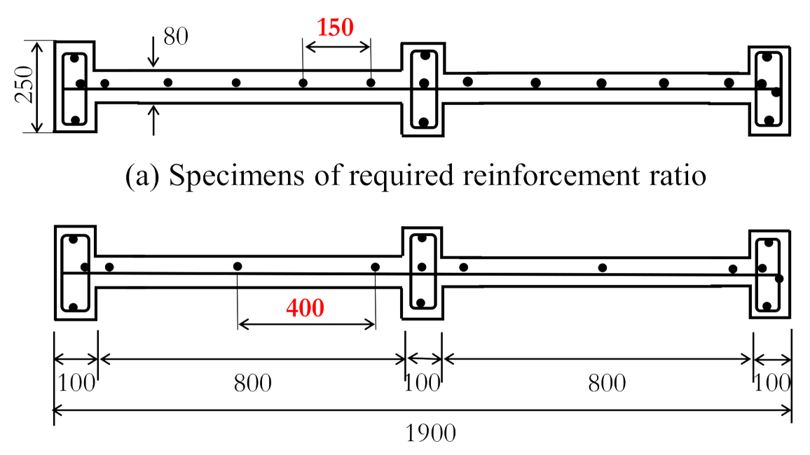
To evaluate structural performance of current R-SHCC structural walls, six wall specimens were manufactured with the experimental variables with the main material being SHCC or concrete, and with two different reinforcement ratios in the horizontal and vertical reinforcing steel bars, ρ h and ρ v , respectively. All the reinforcements used in each specimen were deformed D10 steel bars, which had a nominal diameter of 9.53mm and a measured yield stress of 383 MPa. Two specimens, RCW-N and RCW-M, as shown in Figure 6, were placed in con-crete as prototypes of conventional RC structural walls, with required (-N) and mini-mum (-M) longitudinal reinforcement ratios. The compressive strength of the concrete at 28 days by the cylinder test was recorded as an average of 32.2 MPa. Figure 7 illus-trates cross-sectional geometries and reinforcement details for two types of wall specimens, and a total of six specimens are shown in Table 4, summarized with ex-perimental variables. Two specimens, SHW-N1 and SHW-N2, were manufactured with SHCC as the main material but their reinforcing steel bars were the same as those of the RCW-N speci-men. The other two SHCC specimens, SHW-M1 and SHW-M2, were assembled with the minimum reinforcement ratio, the same as specimen RCW-M.
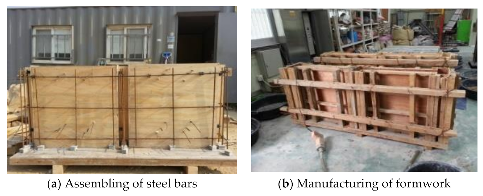
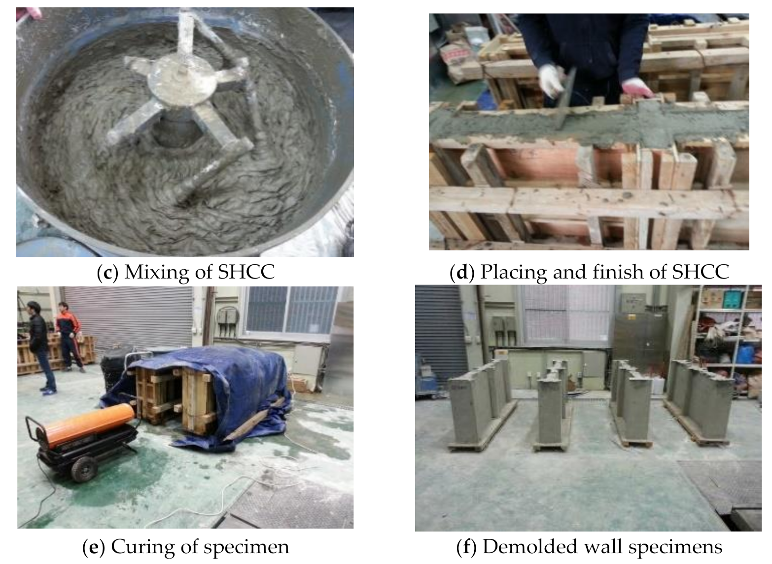
Two specimens of RC walls and four specimens of R-SHCC walls were manufactured following the process shown in Figure 8. Reinforcing steel bars were cut and assembled to fit the dimension and spacing of bars for each specimen, and then settled into each wood formwork, retained the cover with concrete. Each formwork was sufficiently supported by wood square bars in order to prevent side pressure on the formwork during the concrete-pouring process. Fresh SHCC or concrete was poured and compacted to divide into three layers to prevent segregation and poor compactness. After the finishing of fresh SHCC or concrete, each specimen was cured and demolded from the formwork after seven days of curing and continued to cure under wet conditions.

3.2. Splitting Tensile Strength

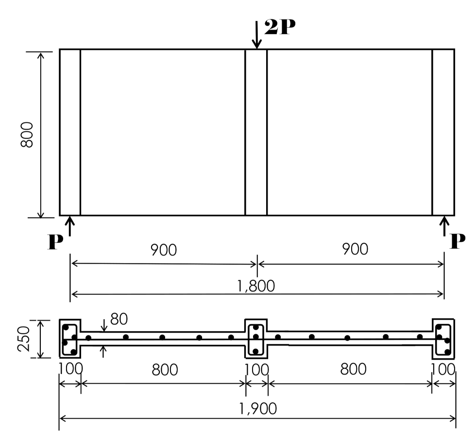
Wall specimens were tested by a three-point loading setup under a simply supported condition, as shown in Figure 9. The pure span length between two supports of both ends was 1800 mm and a transverse load at midspan was applied until each wall specimen reached failure. The loading test was set up on a universal testing machine (UTM) which had a capacity of 1000 kN, as the photos show in Figure 10. The transverse deflection at the midspan was measured using linear variable differential transducers (LVDTs) installed on the midspan bottom surface in the vertical direction. On a surface at 400 mm away from the bottom of midspan, three LVDTs in horizontal, vertical, and diagonal directions were installed, separately, as shown in Figure 10, to estimate the opening of local shear cracks of the wall. Steel gauges were bonded to horizontal reinforcing steel bars both on the top and bottom at midspan.

4. Summaries and Discussions on Wall Load Test

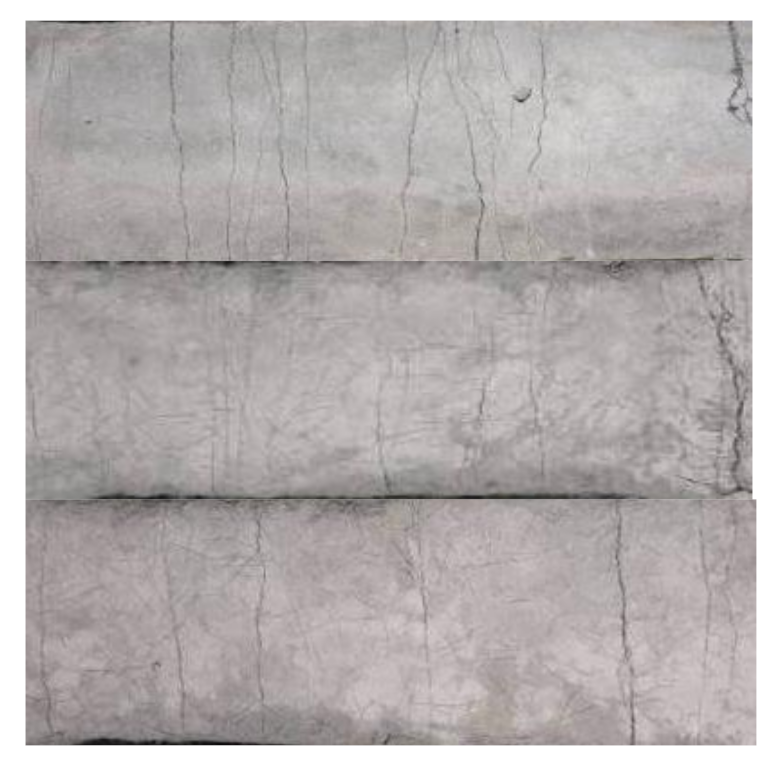
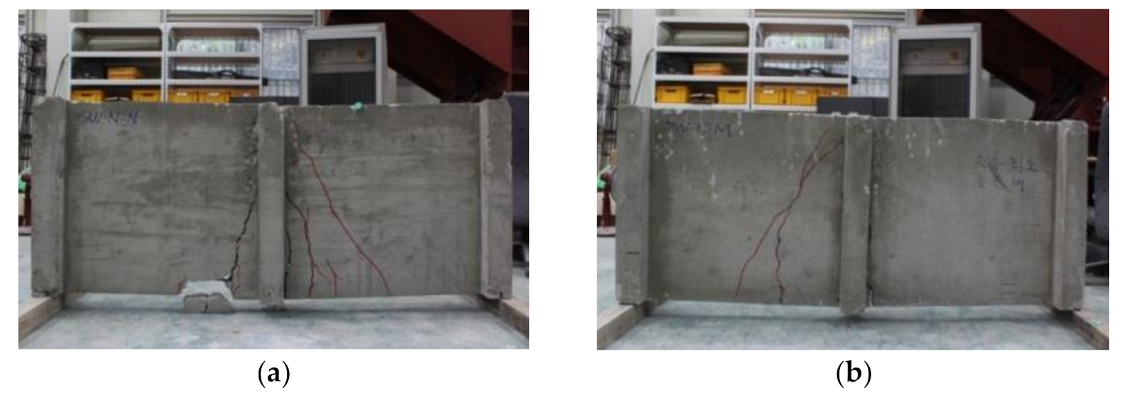
Each wall specimen was loaded transversely on the top at midspan until the specimen reached failure. Cracks and the failure patterns of the two prototypes of conventional RC wall specimens, RCW-N and RCW-M, are shown in Figure 11a,b, respectively. For a specimen of an RC structural wall, RCW-N, cracks initiated vertically at a load of 33 kN on the bottom surface near the midspan and shear cracks extended from the bottom to the top of the wall. The crack width expanded according to the increase in the load. After the wall reached initial yielding of tensile reinforcing bars, in a few cracks, the localization by expansion of crack width accelerated in the vertical and diagonal directions. The slope of the transverse load and deflection curve at midspan rapidly decreased but the degradation in the load did not happen until the load reached its peak point, as shown in Figure 12. After a maximum load was measured at about 160 kN, the load rapidly degraded and the specimen reached failure by crack localizations caused by the expansion of crack width in a few cracks, which were already present due to shear and bending at the initial stage of loading.
The RCW-M specimen showed nearly the same tendency to predict a load and deflection curve until reinforcing steel bars initially yielded, but a few local cracks produced by shear prominently occurred on the surface of the concrete wall in the diagonal direction. Cracks initiated at a load of 25 kN and shear cracks expanded according to the increase in load. Both the maximum load, which was recorded at 149 kN, and the deformation capacity were lower than those of RCW-N. RCW-M finally reached shear failure, as shown in Figure 11, by the expansion of the width of local shear cracks. It was attributed to failure by shear because the RC wall specimen was designed with minimum reinforcement ratios both in the horizontal and vertical directions.
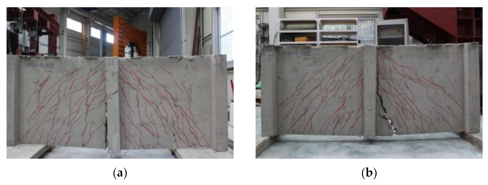
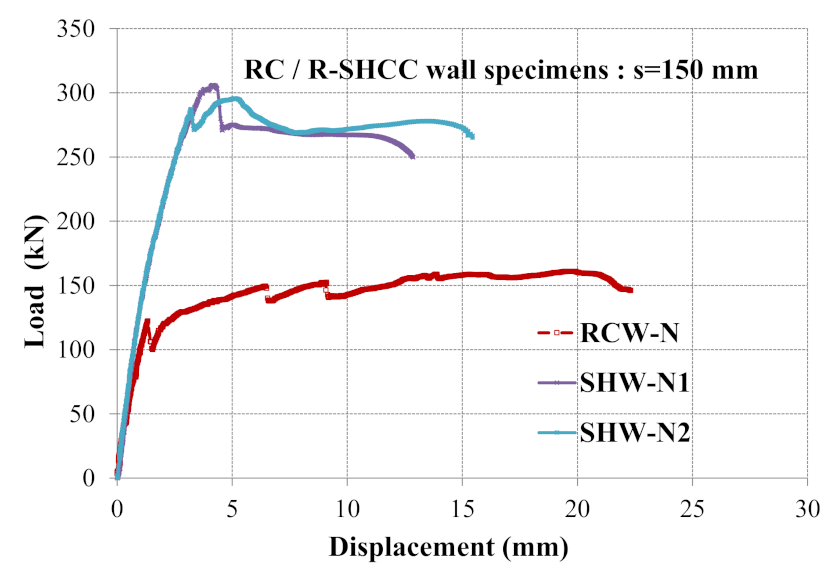
The cracks and failure patterns for R-SHCC structural wall specimens SHW-N1 and SHW-N2, in which the spacing of reinforcing steel bars was 150 mm and designed to have normal reinforcement ratios, are shown in Figure 13. For SHW-N1, accordingly with the increase in the transverse load, microcracks caused by shear and bending initiated on the surface of the SHCC wall at a load level of about 35 kN, but were not easy to observe with the naked eye. After reaching a load of over 90 kN, multiple microcracks both in the vertical and diagonal directions widely spread out on the surface of the SHCC wall and could be observed with one’s eyes but crack localizations could not be seen. Before a yield load was reached, the degradation of the transverse stiffness of SHW-N1 was not noticeable in comparison with the two specimens of RC walls because the cracks on the surface of the R-SHCC wall were restrained by fibers, preventing the widths of the cracks from extending. In comparison with RC wall specimens, similar tendencies of the crack control induced by multiple microcracks, the mitigation of the transverse stiffness degradation, and the enhancement of the transverse load-carrying capacity were also observed for SHW-N2, as shown in Figure 14. The peak transverse load was measured at 302 and 298 kN for SHW-N1 and SHW-N2, respectively. These decreased once after maximum load but ductile deformed behavior continued until the failure of the wall was reached by localizations caused from wide openings of bending cracks.
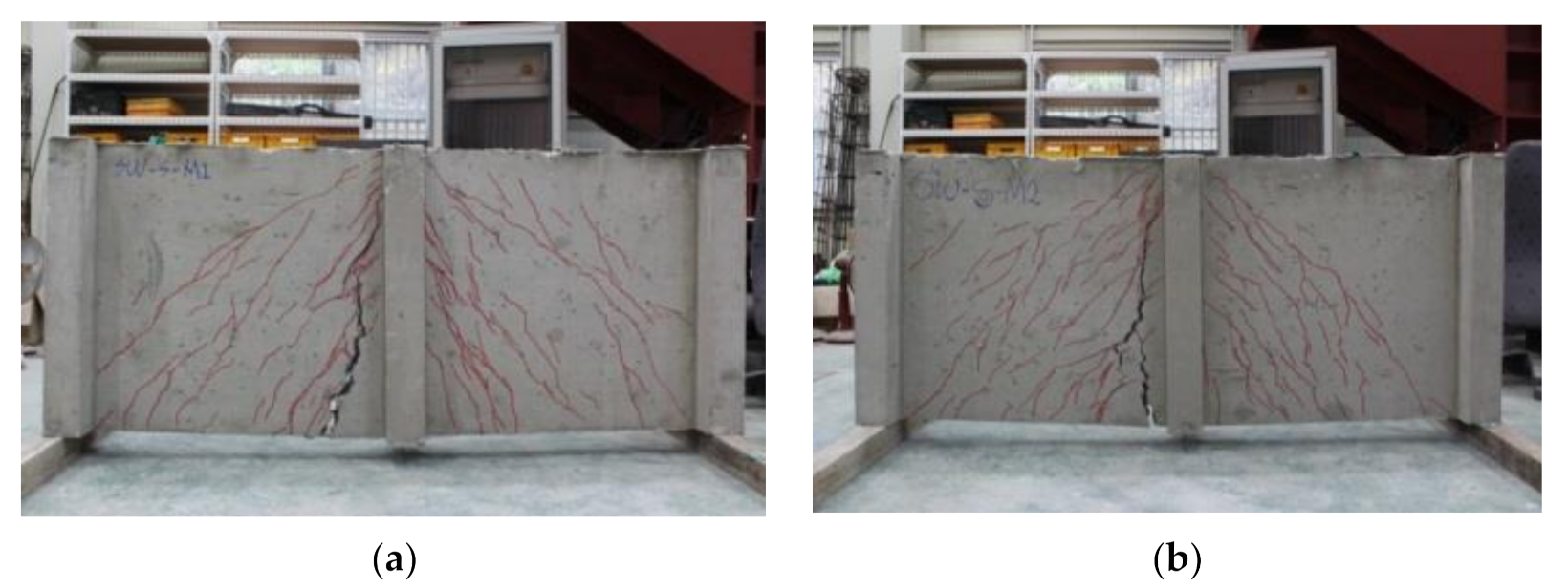
Two specimens of R-SHCC structural walls, SHW-M1 and SHW-M2, were designed with minimum reinforcement ratios and their cracks and failure patterns are shown in Figure 15a,b, respectively. For the two specimens, multiple microcracks induced by shear in the diagonal direction and bending in the vertical direction widely spread on the SHCC wall surface. As observed in SHW-N1 and SHW-N2, until a yield load was reached, the degradation of the transverse stiffness of the wall was less compared with the specimens of RC walls, and crack localizations were also not observed. Despite minimum reinforcement ratios, with spacing of 380 and 400 mm in the horizontal and vertical directions, respectively, the cracked stiffness of the wall was not seriously degraded because the SHCC sufficiently restrained openings and localizations of cracks. As shown in Figure 16, the maximum transverse load was at 219 and 264 kN for SHW-M1 and SHW-M2, respectively. These decreased once after a maximum load but a highly ductile deformation response was sustained until the failure of the wall was reached by the opening of localized bending cracks as seen in SHW-N1 and SHW-N2, which were designed with normal reinforcement ratios.
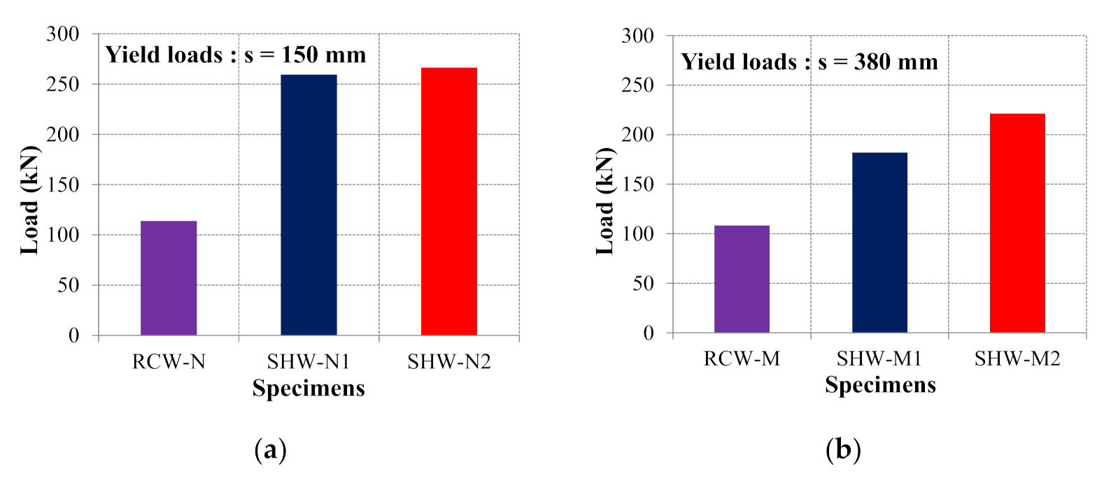
Transverse yield and maximum loads for six specimens of RC or R-SHCC walls were compared, as shown in Figure 17 and Figure 18. For both cases of walls designed with normal and minimum reinforcement ratios, the load levels of R-SHCC walls at yielding and ultimate stages were higher than those of RC walls. The values for R-SHCC walls exceeded those of RC walls in yield and maximum loads for walls designed with normal reinforcement ratios by 2.3 and 1.81 times, respectively; and by 1.87 and 1.62 times for walls designed with minimum reinforcement ratios, respectively. Similar tendencies were also observed in the comparison of the secant stiffness of each wall, as shown in Figure 19, in which the secant stiffness of a wall was calculated from the load and displacement curve between zero and a yielding point. The two R-SHCC walls compared with an RC wall had 1.14 times higher normal reinforcement ratios and 1.52 times higher minimum reinforcement ratios. Despite minimum reinforcement ratios, SHW-M1 and SHW-M2 R-SHCC walls showed excellent structural performance in load-carrying capacities as well as in maintaining a sufficient stiffness after cracks occurred compared with a specimen of RCW-M. Applications of SHCC to structural walls demonstrated that SHCC had advantages in controls of bending and shear cracks, retardations of crack localizations, and minimizations of reinforcing steel bars.

5. Conclusions

As an innovative approach to RC structural walls, SHCC as a high-ductility fiber–cement composite was applied to the design of structural walls, and some conclusions were obtained after evaluating transverse wall loading tests on six specimens of RC and R-SHCC structural walls.
For specimens designed both with normal and minimum reinforcement ratios, in comparison with specimens of conventional RC structural walls, R-SHCC structural walls specimens provided innovative structural performance with considerable enhancements in yield and maximum load capacities, excellent inhibition of stiffness degradation after cracks were initiated on surfaces of a wall, and efficient retardations of crack localizations so as to improve failure induced by wide opening of crack width on the wall subjected to bending moments or shear forces.
For specimens designed with minimum reinforcement ratios in both the horizontal and vertical directions, it was demonstrated that compared with specimens of RC walls, specimens of R-SHCC walls showed reliable structural responses in the control of bending and shear cracks on surfaces of the wall and the increase in the overall load-carrying capacities of the wall. Despite minimum reinforcement ratios, the use of SHCC in a wall showed improved responses to minimize damage and failure caused by localized cracks under bending and shear compared with the use of normal reinforcement ratios in an RC wall.
According to the level of seismic design, the spacing of reinforcing steel bars should be very narrow and complicated with tight spacing of tied bars as in seismically special RC shear wall design. As an innovative approach in the design of special RC shear walls, therefore, the applications of SHCC could provide an alternative to improve the complication of reinforcement details in the design of shear walls, especially in a moderate to strong seismic zone.

Author Contributions

Writing—review & editing, H.-K.K.; Writing—Original draft & editing, C.-G.C.; Validation, S.-J.L., Y.H.L. and T.K. All authors have read and agreed to the published version of the manuscript.

Funding

This research was supported by a National Research Foundation of Korea grant (2019R1A4A1028116), funded by the Ministry of Education, Korea; and by a research fund from Chosun University (2019), Korea.

Institutional Review Board Statement

Not applicable.

Informed Consent Statement

Not applicable.

Data Availability Statement

Not applicable.

Conflicts of Interest

The authors declare no conflict of interest.

References

  1. ACI. Building Code Requirements for Structural Concrete (ACI 318-19); American Concrete Institute: Farmington Hills, MI, USA, 2019. [Google Scholar]
  2. AIK. Korean Building Code and Commentary (KBC 2016); Architectural Institute of Korea: Seoul, Korea, 2016. [Google Scholar]
  3. Cervenka, V.; Gerstle, K.H. Inelastic Analysis of Reinforced Concrete Panels, Part I: Experimental Verification and Application. Int. Assoc. Bridge Struct. Eng. Publ. 1972, 32, 25–39. [Google Scholar]
  4. Darwin, D.; Pecknold, D.A. Analysis of RC Shear Panels under Cyclic Loading. J. Struct. Eng. ASCE 1976, 102, 355–369. [Google Scholar]
  5. Massone, L.M.; Wallace, J.W. Load-Deformation Responses of Slender Reinforced Concrete Walls. ACI Struct. J. 2004, 101, 103–113. [Google Scholar]
  6. Segura, C.L.; Wallace, J.W. Seismic performance limitations and detailing of slender reinforced concrete walls. ACI Struct. J. 2018, 115, 849–859. [Google Scholar] [CrossRef]
  7. Zhang, H.M.; Lu, X.L.; Duan, Y.F.; Zhu, Y. Experimental study on failure mechanism of RC walls with different boundary elements under vertical and lateral loads. Adv. Struct. Eng. 2014, 17, 361–379. [Google Scholar] [CrossRef]
  8. Abdullah, S.A.; Wallace, J.W. Reliability-Based Design Methodology for Reinforced Concrete Structural Walls with Special Boundary Elements. ACI Struct. J. 2020, 117, 17–29. [Google Scholar] [CrossRef]
  9. Paulay, T.; Priestley, M.J.N. Seismic Design of Reinforced Concrete and Masonry Buildings; Wiley & Sons: New York, NY, USA, 1992; p. 744. [Google Scholar]
  10. Priestley, M.J.N.; Seible, F.; Calvi, G.M. Seismic Design and Retrofit of Bridges; John Wiley & Sons: New York, NY, USA, 1996; p. 686. [Google Scholar]
  11. Li, V.C. From Micromechanics to Structural Engineering—The Design of Cementitious Composites for Civil Engineering Applications. J. Struc. Mech. Earth Eng. 1993, 10, 37–48. [Google Scholar]
  12. Blanco, I.; Poggetto, G.D.; Morrone, B.; Tranquillo, E.; Barrino, F.; Catauro, M. Fly Ash Filled Geopolymers: Preparation and Thermal Study. Macromol. Symp. 2020, 389, 1900052. [Google Scholar] [CrossRef]
  13. Cho, C.G.; Ha, G.J.; Kim, Y.Y. Nonlinear Model of Reinforced Concrete Frames Retrofitted by In-Filled HPFRCC Walls. Struct. Eng. Mech. 2008, 30, 211–223. [Google Scholar] [CrossRef]
  14. Cho, C.G.; Kim, Y.Y.; Feo, L.; Hui, D. Cyclic Responses of Reinforced Concrete Composite Columns Strengthened in the Plastic Hinge Region by HPFRC Mortar. Compos. Struct. 2012, 94, 2246–2253. [Google Scholar] [CrossRef]
  15. Kanda, T.; Li, V.C. Interface Property and Apparent Strength of a High Strength Hydrophilic Fiber in Cement Matrix. ASCE J. Mater. Civ. Eng. 1998, 10, 5–13. [Google Scholar] [CrossRef] [Green Version]
  16. Lee, B.Y.; Cho, C.G.; Lim, H.J.; Song, J.K.; Yang, K.H.; Li, V. Strain Hardening Fiber Reinforced Alkali-Activated Mortar—A Feasibility Study. Constr. Build. Mater. 2012, 37, 15–20. [Google Scholar] [CrossRef]
  17. Li, V.C.; Hashida, T. Engineering ductile fracture in brittle matrix composites. J. Mater. Sci. Lett. 1993, 12, 898–901. [Google Scholar] [CrossRef] [Green Version]
  18. Lin, Z.; Li, V.C. Crack Bridging in Fiber Reinforced Cementitious Composites with Slip-hardening Interfaces. J. Mech. Phys. Solids 1997, 45, 763–787. [Google Scholar] [CrossRef]
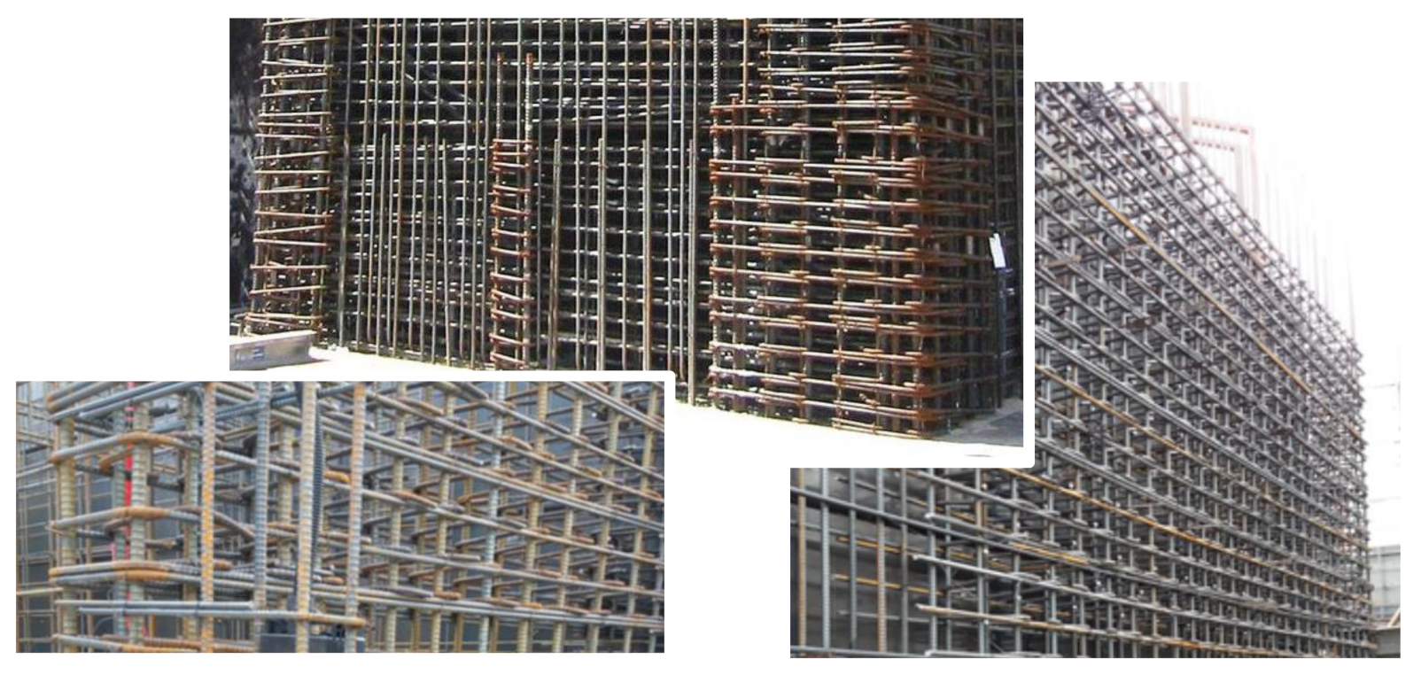
Figure 1. Narrow spacing of steel reinforcing bars in a seismic design of reinforced concrete (RC) shear walls.
Sustainability 13 03607 g001
Figure 2. Mixing materials for strain-hardening fiber cementitious composites (SHCC).
Sustainability 13 03607 g002
Figure 3. Method of direct tensile test.
Sustainability 13 03607 g003
Figure 4. Multiple microcracks after direct tensile test.
Sustainability 13 03607 g004
Figure 5. Photo of SHCC panel bending test.
Sustainability 13 03607 g005
Figure 6. Reinforcement details of wall specimens.
Sustainability 13 03607 g006
Figure 7. Cross-sectional dimensions and reinforcement details of wall specimens.
Sustainability 13 03607 g007
Figure 8. Manufacture process of structural wall specimens.
Sustainability 13 03607 g008aSustainability 13 03607 g008b
Figure 9. Schematic of three-point loading test.
Sustainability 13 03607 g009
Figure 10. Photos of setup for structural wall loading test.
Sustainability 13 03607 g010
Figure 11. Failure of reinforced concrete (RC) wall specimens: (a) RCW-N; (b) RCW-M.
Sustainability 13 03607 g011
Figure 12. Measured load-deflection curves of RC wall specimens.
Sustainability 13 03607 g012
Figure 13. Failure of R-SHCC specimens with normal reinforcements: (a) SHW-N1; (b) SHW-N2.
Sustainability 13 03607 g013
Figure 14. Measured load–deflection curves of specimens with normally reinforcements.
Sustainability 13 03607 g014
Figure 15. Failure of reinforced and strain-hardening fiber cementitious composites (R-SHCC) specimens with minimum reinforcements: (a) SHW-M1; (b) SHW-M2.
Sustainability 13 03607 g015
Figure 16. Measured load–deflection curves of specimens with minimum reinforcements.
Sustainability 13 03607 g016
Figure 17. Comparison of yield loads: (a) normal reinforcements; (b) minimum reinforcements.
Sustainability 13 03607 g017
Figure 18. Comparison of maximum loads: (a) normal reinforcements; (b) minimum reinforcements.
Sustainability 13 03607 g018
Figure 19. Comparison of secant stiffness: (a) normal reinforcements; (b) minimum reinforcements.
Sustainability 13 03607 g019
Table 1. Characteristics of polyvinyl alcohol (PVA) fiber.
Density (g/mm3)Length (mm)Diameter (μm)Young Modulus
(GPa)
Surface treatmentTensile Strength (MPa)
1.3123940Oiling agent1600
Table 2. Mixing proportions of SHCC for a cubic meter. W/B, water/binder ratio; OPC, ordinary Portland cement; FA, fly ash; BFS, blast-furnace slag; PCSP, polycarboxylate superplasticizer; HPMC, hydroxypropyl methylcellulose.
W/B
wt
%
S/C
wt
%
FA/B
wt
%
Slag/B
wt
%
Unit, kg/m3
WBOPCFABFSSilica SandPCSPHPMCDefoamerPVA Vol %
457120203758835001671676920.370.180.452.0
Table 3. Splitting tensile strength of concrete subjected to high temperatures.
SHCC
Specimens
Stress at Initial
Cracking (MPa)
Max. Tensile
Stress (MPa)
Ultimate Tensile
Strain (%)
13.64.13.2
22.73.73.1
33.74.24.5
Average3.33.83.6
Table 4. Experimental variables of structural wall specimens.
Specimen
Name
PVA
Volume
Main
Materials
Horizontal Bars
Spacing   ( ρ h )
Vertical Bars
Spacing   ( ρ v )
RCW-N-Concrete150 mm (0.00597)150 mm (0.00583)
SHW-N12.0%SHCC150 mm (0.00597)150 mm (0.00583)
SHW-N2
RCW-M-Concrete380 mm (0.0020)400 mm (0.0012)
SHW-M12.0%SHCC380 mm (0.0020)400 mm (0.0012)
SHW-M2
Publisher’s Note: MDPI stays neutral with regard to jurisdictional claims in published maps and institutional affiliations.