Abstract
The doubly-fed induction generator (DFIG) uses the rotor’s kinetic energy to provide inertial response for the power system. On this basis, this paper proposes an improved torque limit control (ITLC) strategy for the purpose of exploiting the potential of DFIGs’ inertial response. It includes the deceleration phase and acceleration phase. To shorten the recovery time of the rotor speed and avoid the second frequency drop (SFD), a small-scale battery energy storage system (BESS) is utilized by the wind-storage combined control strategy. During the acceleration phase of DFIG, the BESS adaptively adjusts its output according to its state of charge (SOC) and the real-time output of the DFIG. The simulation results prove that the system frequency response can be significantly improved through ITLC and the wind-storage combined control under different wind speeds and different wind power penetration rates.
1. Introduction
1.1. Background and Motivation
As environmental problems become more and more serious, the research on wind energy and other renewable energy sources has attracted great attention. With the development of wind energy and the gradual maturation of technology, the proportion of wind power in power systems has been increasing [1,2]. Because of its variable speed operation and independent control of active and reactive power, the doubly-fed induction generator (DFIG) is one of the most widely used technologies [3]. However, a DFIG usually operates in the state of maximum power point tracking (MPPT). Its rotor speed is decoupled from the system frequency, resulting in a reduction in the inertia of the power system. Moreover, it cannot provide active power support when the system has an active power shortage [4]. The continuous increase of wind power capacity seriously threatens the stability of the frequency. Therefore, allowing DFIG to participate in system frequency regulation control is essential for promoting wind power consumption and ensuring the safe and stable operation of the grid.
1.2. Literature Review
1.2.1. The Control Strategies of DFIG Participating in Primary Frequency Regulation
At present, the frequency control methods of DFIG participating in the frequency regulation mainly include two types [5]: The first type is deloaded operation of the unit through over-speed or pitch changes [6,7,8,9]. DFIG sacrifices part of the economic benefits and runs at the sub-optimal power point, so that a certain amount of power can be reserved to provide frequency support when the system frequency fluctuates. However, the wind turbine’s long-term deloaded operation requires a reasonable balance of economy to avoid most wind turbines from participating in load reduction, which causes economic loss. The other is to use the rotor kinetic energy of the wind turbine to provide short-term power support. This method can take advantage of the wide speed range of DFIGs so that the DFIGs have considerable inertial response capability [10].
The typical control method that uses rotor kinetic energy to provide temporary power support is proportional derivative control [11]. The system frequency deviation is added to the active power control loop of DFIG through the proportional differentiation link. The derivative link allows the DFIG to simulate the inertial response similar to the synchronous generator, and the proportional link can effectively increase the system damping. Reference [12] proposed a short-term power support control strategy. This method has high controllability, and the inertial response capability will not attenuate with the decrease of rotor speed. However, the improper setting of the constant power output value will cause DFIG to stall. The excessive power drop at the moment of speed recovery may easily cause the second frequency drop (SFD). Aiming at addressing the problem of SFD, [13] proposed corresponding control methods under different wind speeds and wind power penetration rates. Nevertheless, this literature is an analysis conducted in the scenario of microgrid islands. There is less consideration for power grids with larger capacity synchronous machines and wind turbines. A torque limit control (TLC) strategy is proposed in [14], which ensures that the rotor speed converges within the minimum speed limit. However, in [14], the power drops too fast during the initial stage of deceleration, which will affect the effect of improving the frequency nadir, and although a small amount of power reduction in the acceleration phase can improve SFD, it takes longer to recover the rotor speed.
How to use the rotor’s limited kinetic energy to provide more effective support for the system, restore the rotor speed faster and avoid SFD, obtain a better frequency response are the problems studied in this paper.
1.2.2. Application of Battery Energy Storage Systems (BESSs) in Grid Frequency Regulation
In recent years, the BESS has become widely used in grid-assisted frequency regulation due to its flexible power regulation [15,16]. Moreover, BESS equipment has been rapidly developed and applied in renewable-energy technologies [17], and many experts and scholars have launched extensive research work on energy storage control strategies [18,19,20,21].
A wind-storage frequency regulation control system with a battery state of charge (SOC) feedback link is proposed in [18]. According to the battery’s SOC, the BESS, wind turbine, and conventional units are controlled in turn. Reference [19] realizes the wind turbine’s rotor kinetic energy control through PID controller and realized the speed recovery link with a fuzzy controller. Then it puts forward a wind-storage combined control and simulates under different wind speeds. References [20,21] adopt the inertia response method of TLC to enhance the inertia response capability of the wind turbine. Combined with BESS, it improves the SFD when the speed is restored. However, they have insufficient consideration of the impact of SOC on BESS and SOC recovery strategies, which may cause over-discharge of the BESS and reduce its life.
1.3. Proposed Method and Contributions
This paper proposes a wind-storage combined control strategy based on improved torque limit control (ITLC). ITLC includes the deceleration phase and acceleration phase. In the deceleration stage, the DFIG provides constant active power support until the rotor kinetic energy reaches the lowest limit or the frequency approaches the lowest point. The active power output decreases linearly with the rotor speed until it is equal to the mechanical power. In the acceleration phase, the DFIG reduces its active power with time and maintains it until meeting MPPT, and then the DFIG follows the MPPT curve to complete the rest of the speed recovery process.
In the frequency regulation phase, DFIG provides power support for the system according to the ITLC curve. In the speed recovery phase, the BESS adjusts the output according to SOC to provide power to the DFIG. It has the following novel features compared with the existing strategies proposed in the literature:
- (1)
- The ITLC proposed in this paper can more effectively play the potential of rotor kinetic energy. It can improve the frequency response of the system.
- (2)
- During the speed recovery phase of ITLC, the BESS can adjust its output according to the SOC, shorten the time required for the speedy recovery, and avoid SFD.
- (3)
- A SOC recovery control strategy is considered, and SOC can be restored automatically when it is not in good condition. It can extend the life of the battery.
1.4. Organization of the Paper
This paper is organized as follows. Section 2 describes the model of wind-storage combined system and analyzes its inertial response to the power system. Section 3 introduces the ITLC mentioned in this paper. In Section 4, the wind-storage combined control strategy is proposed. Section 5 verifies the effectiveness of the control strategy through simulation. Finally, the paper is concluded in Section 6.
2. Modeling and Inertia Analysis of DFIG and BESS
2.1. Modeling of DFIG and BESS
This section describes the model of wind-storage combined system and analyzes its inertial response to the power system. Figure 1 shows the topology of the wind-storage combined system. A BESS is installed at the grid connection point of DFIG. DFIG is composed of a wind turbine, a generator, and a converter. It usually runs in the state of MPPT.
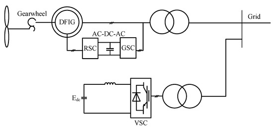
Figure 1.
The topology of wind-storage combined system.
According to the theory of aerodynamics, the output power of a DFIG can be expressed as follows [22]:
where Pm represents the mechanical power of the wind turbine; represents the air density; A represents the area swept by the wind wheel; v represents the speed of wind; represents the tip speed ratio; represents the pitch angle; Cp() represents the wind energy utilization factor represents the intermediate variable.
Figure 2 shows the model of the AC-DC-AC converter, which includes two three-phase two-level inverters. Each inverter consists of a combination of six IGBTs-diode anti-parallel. The AC-DC-AC converter is divided into grid-side converter (GSC) and rotor-side converter (RSC). The GSC maintains the DC bus voltage stability and realizes the constant stator voltage and constant frequency output; the RSC usually adopts the strategy of stator flux orientation to realize the decoupling of the active power and reactive power.
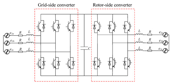
Figure 2.
The model of AC-DC-AC converter.
Figure 3 shows the BESS dynamic model, which is designed based on the built-in battery module in MATLAB/Simulink [23]. In Figure 3, Ebatt is a nonlinear function of several variables; E0 is a constant voltage (V); Exp(s) is the exponential zone dynamics (V); Sel(s) represents the battery mode: its value is set to “0” during battery discharge while it is “1” during battery charging; BattType represents specific type of battery; A is exponential voltage (V); B is the exponential capacity (Ah)−1. The battery energy storage device in this paper comprises a multiple of single cells connected in parallel and series combination.
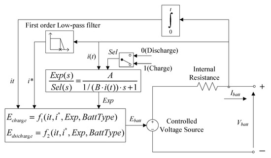
Figure 3.
Equivalent circuit of the generic battery.
2.2. Inertia Analysis
When DFIG is operating at speed ωr, the rotational kinetic energy EWF stored in the rotor can be expressed as:
where J is the DFIG’s moment of inertia.
The inertia constant H is usually used in power systems to characterize the influence of generator inertia on its dynamic behavior:
where SWF and ωs is the apparent power and rated rotor speed of DFIG.
When a BESS is installed at the grid connection point of DFIGs, a wind-storage combined system is constituted through a specific control strategy. Analogous to the definition of the inertial constant above, the inertia constant of the wind-storage combined system can be expressed as:
where EBESS is the energy output of the BESS. (6) shows that the wind-storage combined system has the potential to generate an inertia constant HWF_BESS.
When the system frequency changes, analogy with the rotor motion equation of a synchronous generator, the generalized inertia constant of the wind-storage combined system under the p.u. can be obtained as:
where ΔP is the active power change of the system. Since ω = 2πf, ωp.u. is equal to fp.u., Equation (7) can be expressed as
Integrating (8) within a certain time Δt, the following result can be obtained:
where fp.u.(t + Δt) and fp.u.(t) are the p.u. values of frequency at times t + Δt and t. (9) can be rewritten as:
It can be seen from Equation (10) that when the system frequency fluctuates, a larger HWF_BESS can reduce the frequency change of the system, Equation (6) shows that the wind-storage combined system has a larger inertia constant HWF_BESS, so we can know that the wind-storage combined system can improve the frequency response of the system.
3. Improved Torque Limit Control Strategy
3.1. The Torque Limit of DFIG
The rotor speed of DFIG can be changed within a certain range. Through inertial control, the kinetic energy of the rotor is used to provide short-term power support, which can effectively improve the transient frequency characteristics of the system. At the rated speed ωs, the rotational kinetic energy available for DFIG can be expressed as:
where, ωmin is the minimum speed limit of the rotor, which is set to 0.6 p.u. in this paper, so that the DFIG will not be disconnected due to the low speed when providing active power support, and leave a certain margin to ensure the safe and stable operation of the DFIG.
In the asynchronous motor in the DFIG, the relationship between the electromagnetic torque Te and the stator current and rotor current is:
where np is the number of pole pairs; isd*, isd*, isd*, and isd* are the currents of the stator and rotor dq axis, respectively; Lm is the mutual inductance between the stator and rotor.
As is shown in Equation (12), the electromagnetic torque of DFIG is closely related to the current. To ensure the regular operation of the power converter of DFIG and avoid permanent damage to the converter caused by excessive current, the electromagnetic torque of DFIG should be controlled at a reasonable within range.
At rated speed, the relationship between the power limit PTlim(ωs) and torque limit Tlim of DFIG can be expressed as:
The rapid increase of electromagnetic torque will cause the gearbox’s mechanical stress to exceed the limit range and damage the mechanical components. To avoid this, the value of Tlim is generally set to 1.2 p.u. [24]. When DFIG provides active support for the power grid, the active power output should not exceed the torque limit power corresponding to the speed. Figure 4 shows the power characteristics and limitations of DFIG.
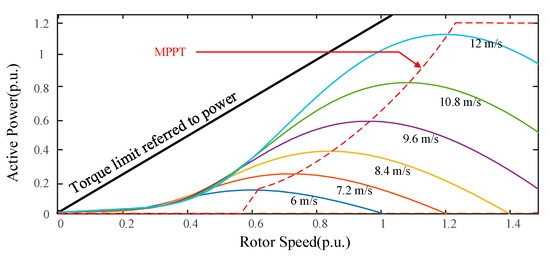
Figure 4.
Power characteristics and limitations of DFIG.
3.2. Implementation Methods
Figure 5 illustrates the implementation of ITLC. The DFIG first provides constant power support during the deceleration phase. The constant active power support is based on the wind penetration rate and the torque limit power corresponding to the initial speed ωr0. After part of the rotor kinetic energy has been released, the active output of the DFIG decreases linearly with the rotor speed. During the acceleration phase, the active output of DFIG first decreases linearly with time and then remains unchanged until it is equal to PMPPT, and then the DFIG follows the MPPT curve to complete the rest of the speed recovery process.
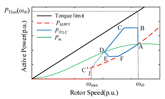
Figure 5.
The relationship between active power and rotor speed of the DFIG under ITLC.
At the beginning of the disturbance, although the DFIG’s active output amplitude in ITLC is smaller than it in TLC [14], the active output time is increased. On the premise of ensuring that the DFIG does not stall, ITLC provides constant power support, which can effectively play the potential of inertial frequency regulation of DFIG. During the acceleration phase, the active output of DFIG first decreases with time until to a lower value. The rotor bears more acceleration power so that the rotor returns to the steady-state value before the disturbance as soon as possible.
The control scheme of ITLC is shown in Figure 6. ITLC is connected to the active control loop of DFIG through the controllable switch 1. The frequency detection module provides a trigger signal for the controllable switch 1. When the system frequency satisfies (14) for a period delay time (50 ms), it can be considered that a frequency accident occurs in the system, and the active power reference value Pref of DFIG switches from PMPPT to PITLC:
where T1 is the start thresholds of frequency deviation, in this paper, T1 = 0.05 Hz.
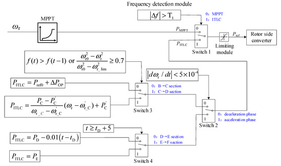
Figure 6.
The control scheme of ITLC.
Figure 7 shows the active output of DFIG under ITLC. The whole process is divided into two phases: the deceleration phase and the acceleration phase. S1 is the energy output during the deceleration phase of DFIG, and S2 is the energy that needs to be absorbed during the acceleration phase of DFIG. When S1 = S2, the operating point will eventually return to the starting point:
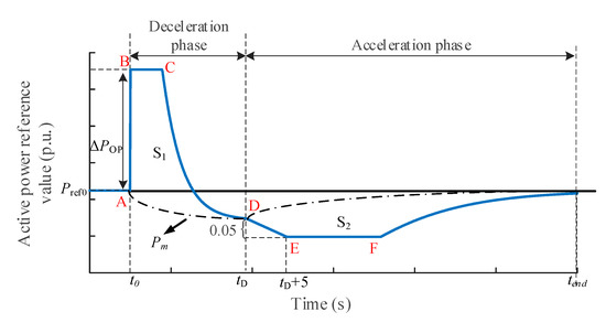
Figure 7.
The curve of Pref under ITLC.
3.2.1. Stage I: Deceleration Phase
The deceleration phase consists of two sections: BC section and CD section. After detecting a disturbance in the system, the controllable switch 3 turns on section BC. In this section, DFIG provides constant power support. PITLC increases by ΔPOP on the steady-state value Pref0 and remains unchanged. PITLC is expressed as:
In TLC [14], ΔPOP increases with the decrease of ωr. It means that the power supported by DFIG is small for a high ωr but large for a low ωr, in which the releasable kinetic energy (H (ω2r − ω2min)) is small, it is more likely to cause over-deceleration of ωr. In order to avoid this, the value of ΔPOP is determined by the releasable kinetic energy of the rotor in this paper. When ωr is close to ωmin, ΔPOP is negligible:
where k0 is an index depending on the wind power penetration rate. As the wind power penetration rate increases, ΔPOP should be reduced. Otherwise, a late frequency nadir might occur. In this paper, k0 for the wind power penetration rate of 20%, 30%, and 40% is set to 0.7, 0.6, and 0.5, respectively. When the wind power penetration rate is more than 40%, k0 should be a positive number less than 0.5.
In section CD, the PITLC of DFIG decreases linearly with speed, and PITLC is expressed as:
where PC is the active power reference value of DFIG operating at point C under ITLC. ω’r_c and P’c are the rotor speed and active power reference value of DFIG operating at point C’ under MPPT. kopt is the MPPT coefficient. In this paper, ω’r_c is 0.61 pu, and kopt is 0.4225.
In the deceleration phase, since the electromagnetic power output by DFIG is more significant than the captured mechanical power, the rotor decelerates and releases the rotational kinetic energy. In order to ensure that DFIG does not go off the grid when participating in frequency regulation and leave a certain margin, when (19) is met for a period delay time(50 ms), controllable switch 3 turns on section CD:
Equation (19) shows that when the system frequency drops to nadir or DFIG has released the rotor kinetic energy accounting for 70% of the total available kinetic energy, the active output of DFIG begins to ramp down (CD section).
The difference between the electromagnetic power and the captured mechanical power of DFIG on the CD section gradually decreases and approaches zero. According to the generator rotor motion equation, the rotor deceleration will gradually slow down and converge to point D. When (20) is satisfied for a period delay time (50 ms), it can be considered that the speed has converged to point D. At this time, the controllable switch 2 turns on the acceleration phase:
3.2.2. Stage II: Acceleration Phase
In the acceleration phase, the controllable switch 4 first turns on the DE section, and the PITLC decreases linearly with time at a speed of 0.01 p.u./s. PITLC is expressed as:
where t is the time, PD and tD are the active power reference value and time of DFIG operating at point D.
When t ≥ tD + 5 s, the controllable switch 4 first turns on the EF section, which means the PITLC of the DE section decreases linearly for 5 s, where PE is the active power reference value DFIG operating at point E. In the EF section, PITLC remains unchanged, and PITLC is expressed as:
With the increase of ωr, PMPPT gradually increases. When PMPPT is equal to PITLC in the EF section, Pref switches from PITLC to PMPPT, and DFIG completes the rest of the rotor speed recovery process under the MPPT control.
The novelties of the proposed control scheme can be summarized as follows:
- (1)
- It ensures the DFIG will not stall and improves SFD. Equation (19) ensures that the rotor’s kinetic energy released by DFIG at point C does not exceed 70% of the total available kinetic energy. It can prevent the active output of DFIG decreases too fast, resulting in insufficient frequency support for the system and SFD.
- (2)
- It can effectively increase the frequency nadir in different frequency responses. When the frequency changes, the DFIG provides constant power support before the frequency drops to nadir. This method can automatically adjust the time for DFIG to provide constant power support for different frequency responses.
- (3)
- By designing such a stage that the active power reference value decreases with time, the active power reference value can be reduced by up to 0.05 p.u. It can increase the difference between the DFIG’s mechanical power and the DFIG’s reference power, improving the rotor speed’s recovery speed. This method can avoid the SFD caused by the sudden drop of the DFIG’s active power output.
4. Wind-Storage Combined Frequency Regulation Control Strategy
4.1. Battery Energy Storage System and Its Control
The ITLC acceleration phase can accelerate the recovery of the rotor speed to a certain extent. However, the energy required for rotor speed recovery is absorbed from the grid. When the active power change of the system is severe, DFIG needs to provide more energy during the deceleration phase. Equation (15) shows that the energy needed to absorb from the grid during the acceleration phase will be much, it will seriously affect the control effect of ITLC.
As shown in Figure 1, this paper considers adding a BESS at the grid connection point of DFIG. The fast and flexible power control capability provides energy support for rotor speed recovery.
In recent years, chemical storage battery technology has developed rapidly, their efficiency is higher than physical energy storage, and their application technology is more mature than electromagnetic energy storage. Through specific control methods, the BESS can flexibly and quickly compensate for the power shortage during DFIG frequency regulation, and its response speed can reach the second level. This paper selects the battery as the research object, and the rated capacity is 20% of the rated power of DFIG.
Although the BESS has flexible control of power output, its installed capacity is small, and the cost is high. Once overcharge or over-discharge occurs, the battery life will be significantly reduced. Therefore, in the process of BESS participating in frequency regulation, the SOC must be considered. Based on the logistic function, the relationship between the unit regulated power of the BESS and the SOC can be shown in Figure 8.
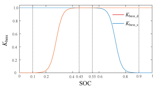
Figure 8.
The relationship between unit regulation power of BESS and SOC.
It can be expressed as a piecewise function:
When SOC(0, SOCmin):
When SOC(SOCmin, SOCmax):
When SOC(SOCmax,1):
where SOCmin and SOCmax are the minimum and maximum of SOC, SOClow and SOChigh are the lower and higher value of SOC. In this paper, SOCmin = 0.1, SOCmax = 0.9, SOClow = 0.45, SOChigh = 0.55. Kbess_c and Kbess_d are unit adjustment power coefficients of BESS during charging and discharging.
When the SOC is less than SOClow, it is considered that the SOC of BESS is insufficient, and SOC recovery is required. The overall control framework of BESS is shown in Figure 9.
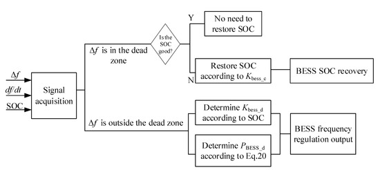
Figure 9.
Control framework of BESS.
When the frequency is in good condition, the BESS examine the SOC and determines whether it needs to be restored; when the frequency falls out of the dead zone, the BESS starts to output power after the frequency is supported by DFIG through ITLC, which assists DFIG to restore the rotor speed, compensates for the power imbalance, and speeds up the rotor speed recovery and avoids SFD.
As shown in Figure 7, according to ITLC, the output of the BESS can be expressed as:
where PBESS_d is the output power of BESS, PE and PD are the output power at points E and D in Figure 7. tE, tD, and tF are the time at points E, D, and F in Figure 7, t is real-time.
The output curve of the BESS can be shown as in Figure 10.
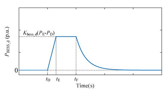
Figure 10.
Output curve of the BESS.
The output method of the BESS are as follows:
The BESS does not work in the frequency steady-state and deceleration phase of DFIG. As shown in Figure 7, at time tD, the frequency support of DFIG to the system ends, and the rotor speed starts to recover. At this time, the BESS’s output power in DE section begins to ramp up.
In the EF section in Figure 7, the output power of the BESS is a constant value. When it is detected at point F that the rotor speed starts to recover along the MPPT curve, BESS’s output power is gradually reduced to zero accordingly. It can avoid the BESS’s output power is greater than the unbalanced power required by the DFIG and prevent the frequency overshoot.
During the BESS’s gradual withdrawal from frequency regulation, its output will be transferred to synchronous generators, and synchronous generators will be used as power support after the BESS exits. With the BESS’s assistance, DFIG does not need to reserve spare capacity, so it always runs in MPPT mode at a steady state. The coordination of the two effectively avoids the SFD that occurs when wind power is withdrawn from frequency regulation, improves the dynamic frequency adjustment capability, and reduces the wind abandonment rate.
The recovery output of the BESS can be expressed by Equation (27):
When the system frequency is in good condition and the SOC state is low, calculate the BESS recovery output according to (27) to complete the recovery of SOC, keep it in good condition and prolong its life.
4.2. Wind-Storage Combined Control Strategy
The flow chart of wind-storage combined control is shown in Figure 11.
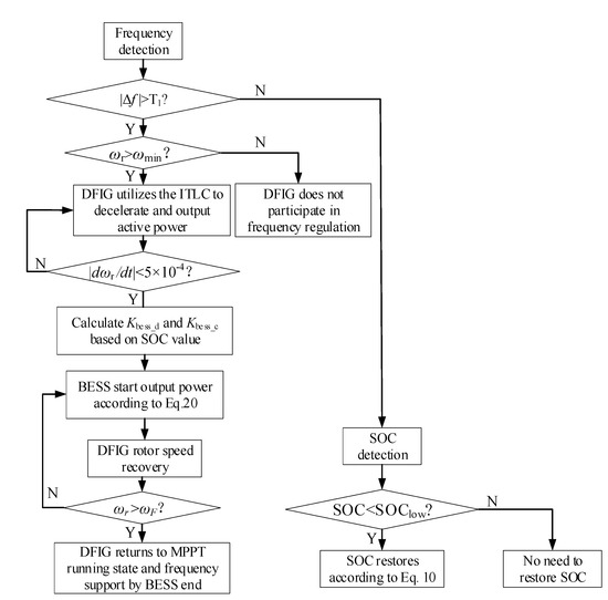
Figure 11.
The flow chat of wind-storage combined control.
The wind-storage combined control strategy proposed in this paper mainly includes the following three stages:
- (1)
- Active power support control of DFIG. When the system active power shortage occurs and the frequency falls out of the dead zone, DFIG uses ITLC to adjust the active output to achieve rapid throughput of the rotor inertia and provide support for the system frequency.
- (2)
- BESS auxiliary speed recovery control. When the DFIG active power support process ends, and the speed meets the convergence condition, the BESS starts to output power according to Equation (26) if the SOC of BESS is in good condition. It can compensate for the active power shortage caused by the DFIG’s speed recovery and accelerate the recovery speed
- (3)
- BESS recovery output control. When the system frequency is in good condition but the SOC of the BESS is low, the BESS resumes its output according to (27).
In the frequency regulation process, the three control methods complement each other to achieve the dual goals of maintaining frequency stability and restoring the SOC state.
5. Simulation and Analysis
In this paper, the feasibility and effectiveness of the proposed wind-storage combined frequency regulation control strategy based on ITLC are verified by the improved IEEE 9-node model example whose wiring diagram is shown in Figure 12. The test example contains 2 synchronous generators and a wind farm composed of several DFIGs. The number of DFIGs varies with the simulation cases. The parameters of the network are shown in Table A1 and Table A2 in Appendix A. Load 4 varies with changes in wind power penetration rate. The initial base capacity is 100 MVA, and the rated wind speed of DFIG is 10 m/s. In this paper, the unit in the simulation system does not participate in the secondary frequency regulation, and the wind speed in each case is a constant value.
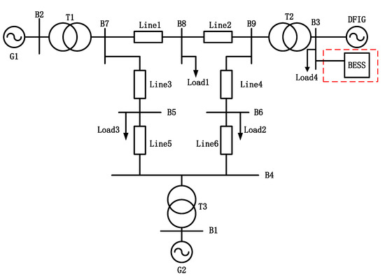
Figure 12.
Diagram of the simulation system.
5.1. Simulation Analysis of ITLC
5.1.1. Scenario 1: Different Wind Speeds
To verify the effectiveness of the proposed control strategy, at t = 5 s in the simulation process, we let Load 3 suddenly increase 40 MW to simulate the power shortage of the system, resulting in a severe frequency decline due to the transient power imbalance. This paper selects three methods for comparison: non-inertia control, TLC in [14], and ITLC. Under three different initial operating conditions with wind speeds of 8 m/s, 10 m/s, and 11 m/s, compare the frequency dynamic characteristics and unit inertial response characteristics of DFIG under the three different methods. The simulation results are shown in Figure 13.
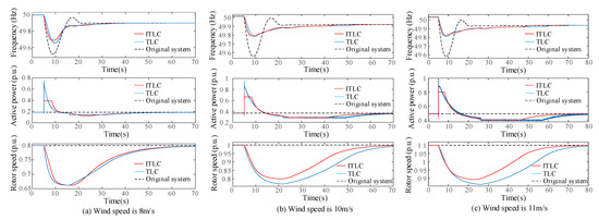
Figure 13.
System frequency response and the inertial response of the DFIG under different wind speeds: (a) Simulation results when wind speed is 8 m/s; (b) Simulation results when wind speed is 10 m/s; (c) Simulation results when wind speed is 11 m/s.
Select two indicators: frequency nadir, the rotor speed recovery time (defined as the time required for acceleration phase of the rotor in Figure 7), the comparison results under different wind speeds are shown in Figure 14.
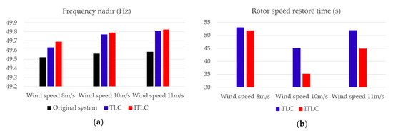
Figure 14.
The comparison of frequency nadir and the speed restore time with different scenarios: (a) Comparison of the frequency nadir; (b) Comparison of the rotor speed restore time.
According to the simulation comparison, we can draw the following conclusions:
From the frequency dynamic characteristic curve and the comparison results, we can know that the system frequency fluctuates greatly when DFIG is not controlled by inertia. When the wind speed is 8 m/s, 10 m/s, and 11 m/s, the frequency nadir is 49.52 Hz, 49.56 Hz, and 49.58 Hz. When the DFIG adopts TLC [14] or ITLC, it can provide transient support for the system frequency by releasing the rotating kinetic energy of the rotor, which can effectively improve the frequency nadir of the system. Compared to the TLC [14], the ITLC has better results, and the effect is best at rated speed (wind speed is 10 m/s). Compared with the DFIG without inertia control, the ITLC reduces the frequency drop by about 35.4%.
In terms of speed recovery, from the inertial response curve of the DFIG and its comparison results, we can know that as the wind speed increases, the rotor speed recovery time under the two control strategies is prolonged. Because the unbalanced power under the ITLC during the acceleration phase is greater, the recovery speed of the rotor in ITLC is faster than that in TLC [14]. When the wind speed is 8 m/s, 10 m/s, and 11 m/s, the recovery time of the rotor under the ITLC is reduced by 1.84%, 22.1%, and 13.46%, respectively, compared with the recovery time under the TLC [14]. When the wind speed is 8 m/s, the DFIG has a small range of speed change because of the minimum speed limit (0.6 p.u.), and the rotor speed converges faster. From Figure 13a, we can know that the DFIG under ITLC has been transferred to MPPT control operation at t = 26 s, and at t = 30 s, the active output curve of the DFIG under the control of ITLC and TLC are approximately coincident. When the DFIG operates at rated speed (10 m/s), compared with the wind speeds of 8 m/s and 11 m/s, the operating parameters of DFIG reach a better state. It can be seen from Figure 13b, the DFIG enters the rotor speed recovery phase earlier under the control of ITLC, and it bears more unbalanced power at this phase, so it has a shorter speed recovery time.
5.1.2. Scenario 2: Different Penetration Rate
The wind power penetration rate reflects the proportion of wind turbines’ connection capacity in the power system. Because the speed of the wind turbine is decoupled from the frequency of the power system, the change of the wind power penetration rate will cause a change of the inertia of the power system and has a significant impact on the frequency system.
In order to verify the applicability of the proposed control strategy under different grid parameters, at rated wind speed, the dynamic frequency characteristics of the system and the inertial response characteristics of DIFG under three different control methods and three different penetration rates are compared. The simulation results are shown in Figure 15.
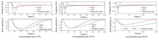
Figure 15.
System frequency response and the inertial response of the DFIG under different penetration rates: (a) Wind power penetration rate is 19.4%; (b) Wind power penetration rate is 30.0%; (c) Wind power penetration rate is 38.9%.
With the increase of wind penetration rate, the improvement of ITLC to frequency response and rotor inertia response becomes more apparent. When the penetration rate is 19.4% and 30.0%, compared with TLC [14], the improvement of the frequency nadir by ITLC is increased by 4.35% and 8.0%, the improvement of rotor speed recovery by ITLC is increased by 22.1% and 48.6%. When the penetration rate is 38.9%, The DFIG using TLC [14] takes a long time to recover the rotor speed, while the DFIG using ITLC needs about 110 s to recover the rotor speed.
It can be known that the ITLC can effectively improve the frequency response of the system and accelerate rotor speed recovery under different penetration rates.
5.2. Simulation Analysis of Wind-Storage Combined Control Strategy
In order to verify the wind-storage combined control strategy proposed in this paper, a BESS is installed at the DFIG grid connection point with a capacity of 20% of DFIG, which is shown in the red box in Figure 12.
At t = 5 s in the simulation process, let the Load 3 suddenly increase 60 MW to simulate the power system’s power shortage. The initial SOC of the BESS is 0.8. Three simulation cases are set as follows:
- Case 1:
- Low wind power penetration level (15.8%)
- Case 2:
- High wind power penetration level (38.9%)
- Case 3:
- Variable wind speed condition
The first two simulation cases aim to evaluate the proposed combined control’s effectiveness under different wind power penetration levels with the same wind speed of 10 m/s. In case 1 of low wind power penetration (15.8%), the wind farm’s capacity is 32.5 MW. In case 2 of high wind power penetration (38.9%), the wind farm capacity is 127.5 MW. In case 3 of low wind power penetration (15.8%), a varying wind speed condition shown in Figure 16 is created by MATLAB/Simulink (Mathworks, Natick, MA, USA) to validate the proposed combined control strategy’s dynamic performance under variable wind speed conditions. The simulation results are shown in Figure 17 and Table 1, Table 2 and Table 3.
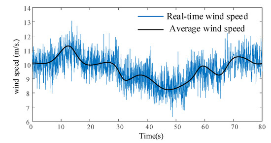
Figure 16.
Variable wind speed profile.
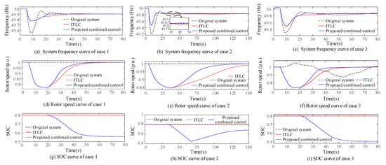
Figure 17.
Simulation results and comparison of the proposed combined control strategy: (a) system frequency curve of case 1; (b) system frequency curve of case 2; (c)system frequency curve of case 3; (d) rotor speed curve of case 1; (e) rotor speed curve of case 2; (f) rotor speed curve of case 3; (g) SOC curve of case 1; (h) SOC curve of case 2; (i) SOC curve of case 3.

Table 1.
Comparisons of simulation results in Case 1.
Table 2.
Comparisons of simulation results in Case 2.
Table 3.
Comparisons of simulation results in Case 3.
In terms of the frequency, from Figure 17a–c, we can know that when the DFIG adopts no control, the frequency drops severely, and there is a significant overshoot during the frequency recovery phase. Both ITLC and the proposed combined control can improve the frequency nadir, and they have the same effect on it. When the DFIG adopts the proposed combined control, the frequency recovery speed will become faster, and only a small overshoot or no overshoot will occur.
According to Figure 17d,e, the rotor recovery speed slows down with the increase of wind power penetration. The proposed combined control can accelerate the recovery speed of the rotor speed. When the wind penetration rate is 15.8% and 38.9%, the proposed combined control can increase the recovery speed by 16.7% and 30.1% compared with ITLC, while SFD is still effectively avoided. It is because the BESS can balance the power absorbed from the system when the DFIG speed needs to be restored. Figure 17f shows that the proposed combined control is also effective when the wind speed changes
It is observed in Figure 17g,i that when the wind penetration rate is low, the change of SOC is always within the allowable range. With the gradual recovery of the rotor speed, the SOC no longer decreases with time, and BESS gradually withdraws from frequency regulation to prevent frequency overshoot. The active power reference of synchronous generators increases slowly, and the frequency recovery process is relatively stable without large frequency fluctuations. When the wind penetration rate is at a high level, because it takes a long time to recover the rotor speed, BESS continues to discharge during this stage. When t = 66 s, the SOC drops to 0.45, and the frequency is stabilized, so the BESS starts to restore SOC according to (27). It prevents over-discharge of BESS. During this process, the system frequency has no significant fluctuations
Based on the above analysis, we can know that the proposed combined control can effectively accelerate the recovery time of the rotor speed and avoid the SFD under different situations. In the context of high wind power penetration, the proposed combined control has a better effect, and it can prevent over-discharge of BESS, which extends the life of the battery.
6. Conclusions and Future Directions
Based on the torque limit curve of DFIG, this paper proposes an improved torque limit control to maximize the potential of DFIG’s inertial response. The proposed control’s feasibility and effectiveness are verified in MATLAB/Simulink under different wind speeds and different wind power penetration rates. In order to accelerate the recovery time of the rotor speed and avoid the SFD, a wind-storage combined control strategy between BESS and DFIG is proposed to improve the frequency response by taking advantage of BESS’s fast and accurate active power control.
Simulation results show that under different wind speeds and different wind power penetration rates, the ITLC can boost the frequency nadir and has a shorter rotor speed recovery time. Under the rated wind speed, the ITLC has the best improvement effect. By utilizing the wind-storage combined control, the rotor speed’s recovery is further expedited, especially in a high wind penetration rate level. When the wind penetration rate is 38.9%, the proposed combined control can increase the recovery speed by 30.1%, while SFD is still effectively avoided and the SOC of BESS can be restored to an ideal state.
In the future, we will continue studying the appropriate capacity of BESS by applying advanced optimization algorithms so that a tradeoff can be achieved between the optimal frequency regulation performance and minimal investment in the BESS device
Author Contributions
The authors confirm their contributions to the paper as follows: B.H. proposed the idea, did the simulation and wrote the paper; F.T. and D.L. revised the manuscript; Y.L. and X.W. reviewed the results and approved the final version of the manuscript. All authors have read and agreed to the published version of the manuscript.
Funding
This paper study was funded by the National Natural Science Fund Program of China (grant number 51977157).
Institutional Review Board Statement
Not applicable.
Informed Consent Statement
Not applicable.
Data Availability Statement
Not applicable.
Conflicts of Interest
The authors declare no conflict of interest.
Appendix A
Table A1.
IEEE (Institute of Electrical and Electronics Engineers) 9 node network node parameters.
Table A1.
IEEE (Institute of Electrical and Electronics Engineers) 9 node network node parameters.
| Classification | Parameter | Value |
|---|---|---|
| Synchronous generator | Rated voltage Vn | 18 kV |
| Rated power Pn | 100 MW | |
| Stator resistance Rs | 0.00285 p.u. | |
| Straight shaft synchronous reactance Xd | 0.896 p.u. | |
| Straight axis transient synchronous reactance X’d | 0.12 p.u. | |
| Diract-axis sub-transient synchronous reactance X’’d | 0.12 p.u. | |
| Quadrature axis synchronous reactance Xq | 0.896 p.u. | |
| Quadrature axis sub-transient synchronous reactance X’’q | 0.12 p.u. | |
| Inertial time constant H | 6.4 s | |
| Damping coefficent D | 0 | |
| Transformer | Rated voltage Vn1:Vn2 | 18 kV:220 kV |
| Rated capacity Sn | 100 MVA | |
| Equivalent resistance RT | 0.002 p.u. | |
| Equivalent inductance LT | 0.0625 p.u. | |
| Magnetizing inductance LmT | 10 p.u. | |
| Load | Load 1 | 100 MW |
| Load 2 | 30 MW | |
| Load 3 | 116.15 MW |
Table A2.
The paramrters of a single DFIG.
Table A2.
The paramrters of a single DFIG.
| Vn [V] | Pn [MW] | ωnom [rad/s] | T [s] | Rs [p.u.] | Ls [p.u.] | Rr [p.u.] | Lr [p.u.] | Lm [p.u.] | H [s] |
|---|---|---|---|---|---|---|---|---|---|
| 575 | 1.5 | 157.08 | 0.02 | 0.007 | 0.171 | 0.005 | 0.15 | 2.9 | 5.04 |
References
- Garmroodi, M.; Verbič, G.; Hill, D.J. Frequency Support from Wind Turbine Generators with a Time-Variable Droop Characteristic. IEEE Tran. Sustain. Energy 2018, 9, 676–684. [Google Scholar] [CrossRef]
- Global Wind Report 2018. Available online: https://gwec.net/global-wind-report-2018 (accessed on 15 March 2019).
- Li, H.; Zhang, X.; Wang, Y. Virtual Inertia Control of DFIG-based Wind Turbines Based on the Optimal Power Tracking. Proc. Chin. Soc. Electr. Eng. 2012, 32, 32–39. [Google Scholar]
- Yang, D.; Kim, J.; Kang, Y.C.; Zhang, N.; Hong, J. Temporary Frequency Support of a DFIG for High Wind Power Penetration. IEEE Trans. Power Syst. 2018, 5, 3428–3437. [Google Scholar] [CrossRef]
- Tang, X.; Miao, F.; Qi, Z. Survey on frequency control of wind power. Proc. Chin. Soc. Electr. Eng. 2014, 34, 4304–4314. [Google Scholar]
- Bao, Y.-Q.; Yang, L. On deloading control strategies of wind generators for system frequency regulation. Int. Trans. Electr. Energy Syst. 2015, 25, 623–635. [Google Scholar] [CrossRef]
- Zhang, X.; Chen, Y.; Wang, Y.; Zha, X.; Yue, X. Deloading Power Coordinated Distribution Method for Frequency Regulation by Wind Farms Considering Wind Speed Differences. IEEE Access 2019, 9, 122573–122582. [Google Scholar] [CrossRef]
- Vidyanandan, K.V.; Senroy, N. Primary frequency regulation by deloaded wind turbines using variable droop. IEEE Trans. Power Syst. 2013, 5, 837–846. [Google Scholar] [CrossRef]
- de Almeida, R.G.; Pecas Lopes, J.A. Participation of Doubly Fed Induction Wind Generators in System Frequency Regulation. IEEE Trans. Power Syst. 2007, 8, 944–950. [Google Scholar] [CrossRef]
- Dreidy, M.; Mokhlis, H.; Mekhilef, S. Inertia response and frequency control techniques for renewable energy sources: A review. Renew. Sustain. Energy Rev. 2017, 69, 144–155. [Google Scholar] [CrossRef]
- Morren, J.; Haan, S.W.; Kling, W.L. Wind turbines emulating inertia and supporting primary frequency control. IEEE Trans. Power Syst. 2006, 1, 433–434. [Google Scholar] [CrossRef]
- Tarnowski, G.C.; Kjar, P.C.; Sorensen, P.E. Variable speed wind turbines capability for temporary over-production. In Proceedings of the Power Energy Society General Meeting, Calgary, AB, Canada, 26–30 July 2009; pp. 1–7. [Google Scholar]
- Liu, K.; Qu, Y.; Kim, H.; Song, H. Avoiding Frequency Second Dip in Power Unreserved Control during Wind Power Rotational Speed Recovery. IEEE Trans. Power Syst. 2018, 5, 3097–3106. [Google Scholar] [CrossRef]
- Kang, M.; Kim, K.; Muljadi, E. Frequency Control Support of a Doubly-Fed Induction Generator Based on the Torque Limit. IEEE Trans. Power Syst. 2016, 11, 4575–4583. [Google Scholar] [CrossRef]
- Poullikkas, A. A comparative overview of large-scale battery systems for electricity storage. Renew. Sustain. Energy Rev. 2013, 27, 778–788. [Google Scholar] [CrossRef]
- Delille, G.; François, B.; Malarange, G. Dynamic frequency control support: A virtual inertia provided by distributed energy storage to isolated power systems. In Proceedings of the 2010 IEEE PES Innovative Smart Grid Technologies Conference Europe (ISGT Europe), Gothenberg, Sweden, 11–13 October 2010; pp. 1–8. [Google Scholar] [CrossRef]
- Qu, L.; Qiao, W. Constant Power Control of DFIG Wind Turbines with Supercapacitor Energy Storage. IEEE Trans. Ind. Appl. 2011, 1–2, 359–367. [Google Scholar] [CrossRef]
- Dang, J.; Seuss, J.; Suneja, L.; Harley, R.G. SOC feedback control for wind and ESS hybrid power system frequency regulation. In Proceedings of the 2012 IEEE Power Electronics and Machines in Wind Applications, Denver, CO, USA, 21 January 2012; pp. 1–7. [Google Scholar] [CrossRef]
- Miao, L.; Wen, J.; Xie, H.; Yue, C.; Lee, W. Coordinated Control Strategy of Wind Turbine Generator and Energy Storage Equipment for Frequency Support. IEEE Trans. Ind. Appl. 2015, 7–8, 2732–2742. [Google Scholar] [CrossRef]
- Wu, Z.; Gao, W.; Zhang, H.; Yan, S.; Wang, X. Coordinated Control Strategy of Battery Energy Storage System and PMSG-WTG to Enhance System Frequency Regulation Capability. IEEE Trans. Sustain. Energy 2017, 7, 1330–1343. [Google Scholar] [CrossRef]
- Zhao, J.; Li, M.; He, X.; Zhu, R. Control strategy of wind-storage combined frequency regulation based on torque limit control. Trans. Chin. Elec. Soc. 2019, 34, 4982–4990. [Google Scholar]
- Abir, A.; Mehdi, D. Control of permanent-magnet generators applied to variable-speed wind-energy. In Proceedings of the 2017 International Conference on Green Energy Conversion Systems (GECS), Hammamet, Tunisia, 23–25 March 2017; pp. 1–6. [Google Scholar] [CrossRef]
- MathWorks, Battery-Implement Generic Battery Model. Available online: http://www.mathworks.com/help/physmod/sps/powersys/ref/battery.html?s_tid=gn_loc_drop (accessed on 2 March 2021).
- Wang, X. Assessment of system frequency support effect of PMSG-WTG using torque-limit-based inertial control. In Proceedings of the 2016 IEEE Energy Conversion Congress and Exposition (ECCE), Milwaukee, WI, USA, 18–22 September 2016; pp. 1–6. [Google Scholar] [CrossRef]


Publisher’s Note: MDPI stays neutral with regard to jurisdictional claims in published maps and institutional affiliations. |
© 2021 by the authors. Licensee MDPI, Basel, Switzerland. This article is an open access article distributed under the terms and conditions of the Creative Commons Attribution (CC BY) license (http://creativecommons.org/licenses/by/4.0/).