Article

Development of an Ignition System and Assessment of Engine Performance and Exhaust Characteristics of a Marine Gas Engine

Department of Mechanical and Shipbuilding Convergence Engineering, Pukyong National University, Busan 48547, Korea
*
Author to whom correspondence should be addressed.
Sustainability 2021, 13(8), 4097; https://doi.org/10.3390/su13084097
Submission received: 4 March 2021 / Revised: 16 March 2021 / Accepted: 26 March 2021 / Published: 7 April 2021

Abstract

:
In recent years, marine engine manufacturers have become increasingly interested in gas engines as an alternative to diesel engines to address rising crude oil prices and environmental regulations. In this study, a 1.6 MW dedicated gas engine was developed based on a diesel engine with bore 220, stroke 300. The developed gas engine had a precombustion chamber and exhibited excellent performance; the brake mean effective pressure was 2.1 MPa at 1000 rpm and NOx emissions were 50 ppm under 15% O2. In particular, it demonstrated excellent fuel economy with a thermal efficiency of 45%, and its carbon dioxide emissions were ~75% of the conventional diesel engines, thus demonstrating greenhouse gas reduction. These results indicate that suitably developed gas engines can provide a low-cost and energy-efficient alternative to diesel engines.

1. Introduction

The interest in natural gas engines as an alternative to diesel engines has intensified in recent years as crude oil prices have risen and global environmental regulations have become more stringent. Natural gas engines can improve thermal efficiency through lean combustion, owing to combustion of a wide range of fuels [1,2]; meanwhile, the low carbon content of the fuel reduces CO2 emissions, which is crucial in reducing greenhouse gas emissions [1,2]. Natural gas engines also exhibit excellent fuel economy and low fuel costs. Unlike crude oil, natural gas is widely distributed worldwide and offers an advantage in terms of supply and demand. As a result, the demand for gas engines is increasing rapidly. Therefore, many marine engine manufacturers have developed micropilot-type gas engines that inject diesel fuel only for ignition.
Concerns regarding fossil fuel stockpiling and strict legislation against contaminated emissions from internal combustion engines have forced engine designers and manufacturers to continuously pursue improved engine performance and emission characteristics. Extensive research has been conducted to simultaneously improve engine efficiency and reduce emission levels through the application of new technologies, such as engine reduction, new combustion concepts, alternative and/or renewable energy sources, turbocharging, and improved fuel-air mixing. To meet the above-mentioned demands, natural gas has been adopted as an alternative fuel because it is suitable for use in internal combustion engines and has widespread global reserves and acceptable emission behavior. Gas engines are becoming increasingly attractive in applications such as industrial prime mounds, transportation, and stationary power. Further research is also being conducted to improve gas engine performance and emission characteristics and overcome deficiencies in various load plans to become feasible alternatives for various applications. Kalam et al. [3] have previously compared natural gas and gasoline performance in engines. To evaluate the output and emission levels, a bifuel spark ignition (SI) multicylinder engine operated under several partial and full-load test conditions was investigated for either gasoline or natural gas. Results show that while natural gas produced 15–20% less power than gasoline, the brake-specific fuel consumption (BSFC) was lower by 18%. At the same output power, natural gas produced fewer emissions, except for NOx. Klimkiewicz and Teodorczyk [4] investigated direct injection SI engines to improve gas engine performance. A series of frame sealer photographs related to injection and combustion processes was obtained along with the in-cylinder pressure profile. The effect of the spark plug location on gas engine performance was shown to be lower than that of conventional engines. The dual gas injection fuel delivery system also improved engine performance by providing a more stable gas–air mixing ignition function in the combustion chamber. Evans et al. [5] made another comparison of gasoline and natural gas combustion for single-cylinder engines. The authors showed that while much lower emissions could be achieved by natural gas, the brake average effective pressure (BMEP) of natural gas fuel engines was ~12% lower at any ignition timing. As a result, at full load, the gas engine produced ~50% less total hydrocarbons (THCs) and carbon monoxide (CO) than the gasoline engine. When an engine is designed as a dedicated natural gas engine, some parts and systems must be redesigned to provide optimal performance compared to conventional engines. This includes modifications of compression ratios, spark plugs, cooling and lubrication systems, charging entertainment, and gas exchange processes to meet the thermal fluid design criteria. One of the most important considerations for an internal combustion engine is the design of an appropriate camshaft profile. Proper valve timing is required, as the combustion chamber must have the appropriate trapped air:fuel ratio, while the optimum pumping loss and overlapping pumping loss must be achieved simultaneously.
The Miller cycle [6] was initially proposed to improve engine efficiency. This cycle is an over-expanded cycle, i.e., one with a higher expansion ratio than compression ratio. It has recently been proposed as a means of reducing hazardous emissions while maintaining engine efficiency by lowering the engine compression rates and maximizing the gas temperature and pressure in cylinders.
Many reports have described the concept of the Miller cycle engine and investigated various aspects of the Miller cycle engine design and operation. Alsargh et al. [7] and Zhao and Chen [8] conducted theoretical investigations on Miller cycle engine performance and studied the effects of key engine design variables and system inversibility. Endo et al. [9] have described the design of a large commercial (280–1100 kW) gas engine using the Miller cycle principle, claiming a fuel economy advantage of >5% over existing technologies of its class. Gheorghiu and Uberschör [10] studied overextended engines for use in hybrid vehicles and investigated the causes of efficiency loss in common implementations of these cycles. Wang and Lucston [11] and Wang et al. [12] investigated the application of the Miller cycle concept to reduce engine emissions and found that a significant reduction in engine fuel consumption was possible, despite its penalties.
Figure 1 shows the air-standard auto and Miller cycles and the additional work that can be extracted from the Miller cycle (shaded). Heywood [13] showed that it is possible to achieve significant increases in engine efficiency in excessively extended cycles, especially at low compression rates.
The Miller cycle is a modification of the overinflation cycle, which provides a higher expansion ratio than the compression ratio with improved thermal efficiency compared to the conventional internal combustion engine operating conditions [14]. In practice, this difference in expansion ratio can be achieved through a compression stroke that includes a late or early closing of the intake valve. This effectively reduces the compression stroke, but maintains the combustion and expansion processes as normal to extract additional energy before the exhaust process while reducing the brake average effective pressure (BMEP) to improve thermal efficiency [14,15]. The brake mean effective pressure metric is used to define the operation of the actual engine output defined in the brake output. To avoid a short compression stroke, turbochargers or superchargers have been used to maintain a stable BMEP level and thus ensure continued benefits of this cycle [14]. Therefore, the Miller cycle uses boosting to recover the lost charge caused by a smaller displacement during compression. This cycle also provides cooling to the precombustion fuel–air mixture according to the inlet valve closing timing to help minimize the combustion knock problems with SI engine operation prior to ignition [15].
Miller [16] also demonstrated that controlling the paging of the intake valve closure (IVC) and exhaust valve opening (EVO) has a significant impact on engine performance. Similar to the Atkinson cycle [17], the expansion ratio in the Miller cycle exceeds the compression ratio (Figure 1). This can be achieved by either late-intake valve closure (LIVC) or early intake valve closure (EIVC), depending on the engine boost pressure and engine speed [17,18,19,20]. Unlike the Atkinson cycle, however, the Miller cycle can improve engine efficiency without reducing power because of supercharged and turbocharged utilization. In recent years, numerous studies have been conducted to improve engine performance using Miller cycles. Anderson et al. [21] examined the naturally aspirated Miller cycle SI engine using LIVC based on primary and secondary law analysis. The authors found that the LIVC required less fuel to produce the same output compared to the base engine and showed 6.3% higher thermal efficiency at partial loads. In addition, LIVC had better thermal-mechanical criteria owing to the high inlet manifold pressure. We et al. [22] simulated Miller cycles to compare them with standard auto cycles based on thermodynamic models. For Miller cycle applications, superchargers have been recommended because the trapped mass is too low without supercharging, even lower than the default Otto cycle. However, no such loss has been shown in other studies of optimal power density properties for the Atkinson, Miller, and dual cycles [23,24,25].
To overcome the disadvantages of exhaust gas recirculation (EGR), Benazes et al. [26] investigated whether the Atkinson cycle was suitable for lowering the filling temperature in cylinders. This was achieved by advancing the IVC on a medium diesel engine equipped with a fully variable valve drive (VVA) system, maintaining constant inlet and exhaust pressure. The results confirmed that the Atkinson cycles could reduce gas temperature in cylinders along with gas pressure and density during the compression stroke.
Al-Sarki et al. [18] investigated the relationship between thermal efficiency, compression ratio, and expansion ratio for ideal naturally aspirated (air-standard) Miller cycles using finite-time thermodynamics. This model provides instructions for predicting the performance of the Miller cycle engine when the correct model parameters are used. Martins and Lanzanova [27] presented a detailed 1D simulation analysis of the Miller cycle SI engine at full load when driving ethanol hydroxide with different supercharges and valve train configurations. In the study, the effects of IVC timing and camshaft profiles, charge dilution through EGR or excessive air on combustion periods, and temperature in the cylinders were investigated. Detailed evaluations of major losses have also been conducted, and several possible arrangements have been studied. When applying the Miller cycle concept, a diesel engine brake efficiency of >40% has been achieved. They [27] showed that the highest efficiency values were achieved with solenoid-operated valves and initial IVCs. The pumping loss associated with LIVC reduces the appeal of this option. However, the high intake pressure required for very high EIVC cases (>5 bar) makes this option very difficult for current engines. Operation is expected to be practically unachievable at EIVC prior to 460 crank angle (CAD) after ignition TDC.
Gas engine emissions include THCs, CO, CO2, and NOx, among which NOx are the most harmful to the environment. The Miller cycle engine is one of the most promising ways to reduce these emissions as it has a much lower combustion temperature that reduces NOx formation. An experimental study by Wang et al. [28] showed that the application of Miller cycles in standard auto-cycles results in a NOx reduction rate of ~8% and a loss of engine power at full load of only 1%. Similar studies on the Miller cycle concept of Wang and Ruxton [29] showed a significant reduction in NOx.
Konka et al. [30] conducted performance analysis for output and thermal efficiency. The maximum output and thermal efficiency criteria were investigated for air-standard non-reversible double Miller cycles using LIVC. In this study, optimal engine operation and design parameters were achieved through thermodynamic optimization to maximize the output and thermal efficiency. Furthermore, the application of this method to a single-cylinder, direct injection diesel engine was studied experimentally and theoretically. Two Miller cycle approaches, which provided 5 and 10 CAD-delayed IVCs compared to standard conditions, were applied in conjunction with two different camshafts. The results showed that NO and CO2 emissions had decreased by 48% and 2.2%, while HC(hydro-carbon) and CO emissions were increased by 46% and 34%, respectively. Further, effective power and efficiency were decreased by 6.4%, and 9.2% respectively. The optimal condition was defined as 10 CAD delay because of maximum NO reduction [31].
Linaldini et al. [32] investigated the possibility of reducing soot formation at NOx and partial loads and the limitations thereof by applying a Miller cycle on conventional high-speed diesel engines. Analysis was performed using GT power and Kiva-3V simulation tools for engine analysis and in-cylinder analysis, respectively, showing that combustion was essentially cleaner with a 10% and 50% reduction in NOx and soot formation, respectively. However, these authors focused on the dedicated (pure) gas engine to simplify the fuel supply system and engine operating mode, and to improve the characteristics of emission.
Inspired by these developments, we developed a 1.6 MW dedicated gas engine, based on a diesel engine with bore 220, stroke 300. This can be considered as an early stage of gas engine development, with the prospect of expanding the power generation market for sea and land transportation. The developed gas engine is a spark-ignited-type electric gas engine with a precombustion chamber [33]. Herein, we have described the development and performance evaluation of a gas engine in detail.
Further, the potential benefits of applying the Miller cycle concept of small gas engines, which are suitable for applications such as domestic combined heat and power systems, have been investigated. The Miller cycle has the advantage of fuel efficiency over conventional auto-cycle engines, but its engine power density is lower. While friction losses are expected to increase in Miller cycle engines, a brief analysis suggests that the fuel economy benefit of the Miller cycle are greater than that of the Otto cycle. The results of this study suggest that if penalty kicks of engine output density are acceptable, the over-expansion cycle can be used to achieve significant fuel efficiency improvements in small internal combustion engines, along with the reduction in NOx.

2. Gas Engine Development

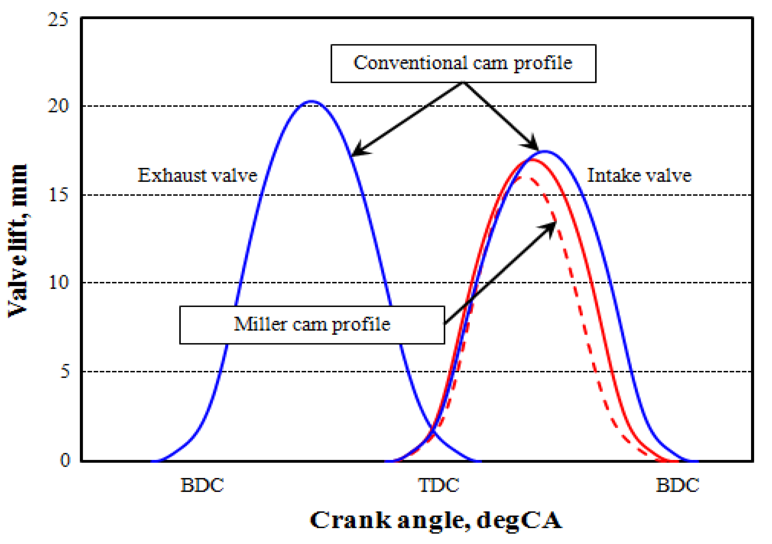
2.1. Concept of the Target Gas Engine

This study is intended to be the first step toward entering the gas engine market. Therefore, we aimed at developing a spark-ignited-type gas engine in an easy and inexpensive manner. The target output of the engine was 1.6 MW (200 kW per cylinder); aiming for the best performance among engines of the same class, the target engine efficiency was 45% [33]. Further, considering land power generation as a future market, the standard NOx emissions were limited to 50 ppm at 15% O2 composition, conforming to the regulations for Korean land power engines. In addition, the target brake mean effective pressure at an engine speed of 1000 rpm was 2.1 MPa, which is significantly higher than that of a typical gas engine. The development goals and operating conditions of the gas engine are summarized in Table 1.
The above-mentioned development objectives—gas engines with a significant level of output performance—are considerably difficult to achieve because of abnormal combustion conditions such as knocking and misfiring [34]. To overcome these challenges, several development technologies were applied.
High-efficiency and high-output gas engines encounter several problems such as knocking and increased NOx emissions owing to high heat loads. We applied the Miller cycle and lean combustion techniques to solve these problems [35,36]. The Miller cycle improves thermal efficiency by reducing the compression work, and this is achieved by closing the intake valve early, as depicted in Figure 2 which of intake cam profile is composed of conventional com profile(blue line) and miller cam profile between red line and red dot line. Further, the Miller cycle reduces knocking and NOx emissions simultaneously by lowering the combustion chamber temperature. These Miller cycles were realized through design calibration of the cam shape and using a high-performance turbocharger to compensate for the reduction in the amount of the intake mixture [37].
Lean combustion enables complete combustion, which can be expected to improve thermal efficiency. However, if the lean level is expanded, it may cause combustion instability. Therefore, an appropriate lean limit must be derived [37]. In this study, NOx reduction was realized as lean combustion [38,39]. Although lean combustion can reduce the temperature of the combustion gases and NOx emissions, it causes several problems such as combustion instability, incomplete combustion, and misfiring. To solve these problems, a precombustion chamber method was applied, and the piston shape and turbulence flow were optimized. A little richer fuel mixture was supplied and ignited by a spark plug in the precombustion chamber, and the leaner mixture in the main chamber was combusted by the flame ejected from the precombustion chamber. The optimization of piston shapes also facilitated lean combustion by activating turbulence and flame propagation.

2.2. Components of the Main Gas Engine

A photograph and key specifications of the 1.6 MW gas engine developed in this study are presented in Figure 3 and Table 2, respectively.

2.2.1. Cylinder Heads and Precombustion Chamber
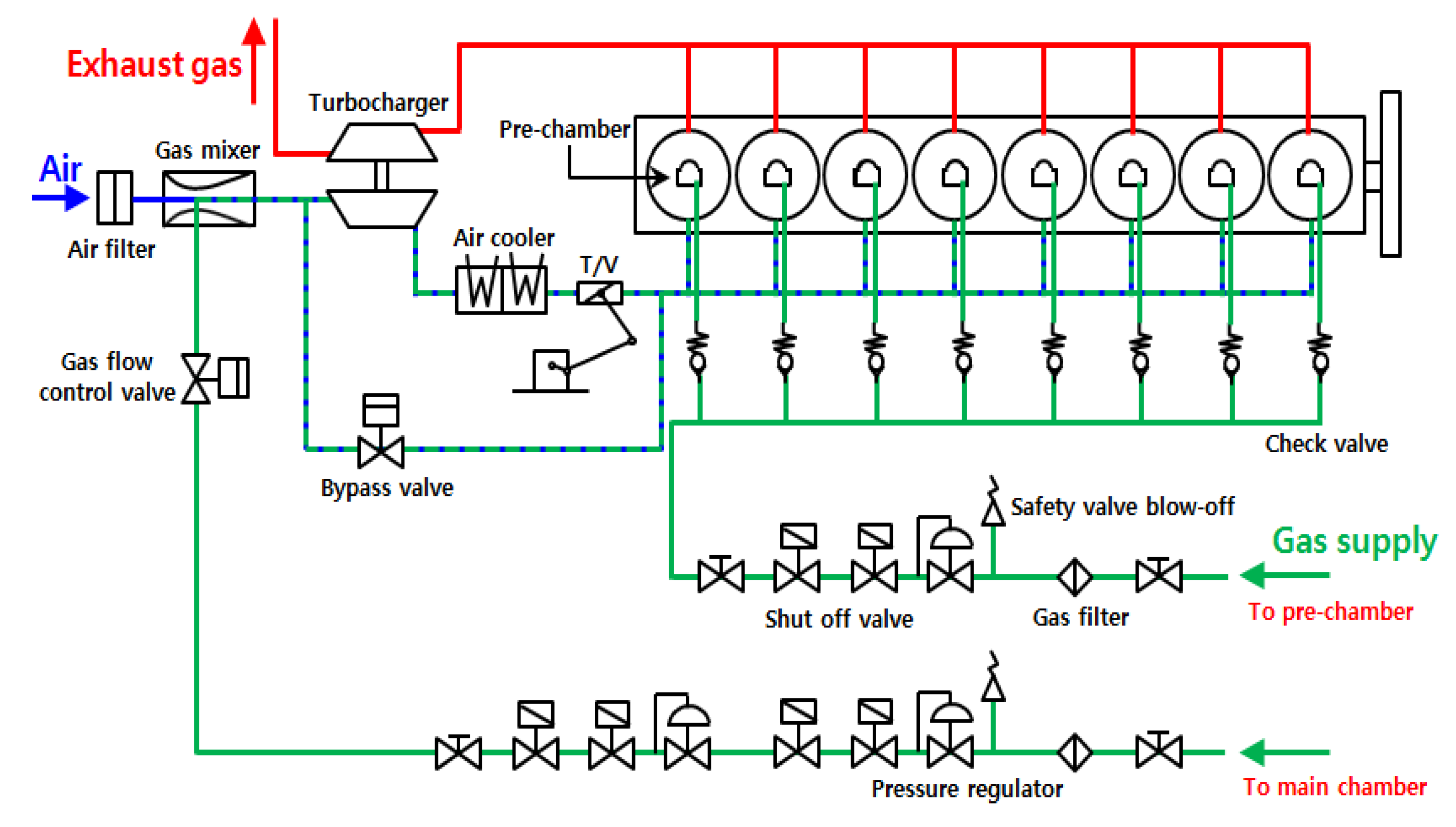
Figure 4 provides an overview of the cylinder head and combustion chamber of the developed gas engine. The cylinder head removed as much unnecessary space as possible (starting air hole, induction hole, injector cooling hole, etc.) to improve the responsiveness in the transition operation area and reduce compression losses. In addition, the cooling system was enhanced to alleviate thermal stress, considering the increased thermal load. The side of the cylinder head was equipped with a knock detection sensor to detect and suppress knock generation; this sensor was connected to the engine control system. The precombustion chamber was installed at the injector position of an existing diesel engine. In the dedicated gas engine, the precombustion chamber should be generally applied to prevent knock generation in the case of approximately over 170 mm bore. Inside the precombustion chamber, a check valve for supplying the gas fuel and a spark plug for ignition of the mixture was installed. The O-ring prevented the leakage of the coolant from the precombustion chamber, and the cylinder head was improved to facilitate the maintenance and repair of the spark plug.

2.2.2. Fuel Supply

As depicted in Figure 5, the gas fuel supply was divided into a low-pressure gas supply system, which primarily supplied the gas fuel to the main combustion chamber, and a high-pressure gas supply system.
The low-pressure gas fuel was supplied to the intake system through two levels of pressure control, wherein the gas fuel was decompressed and mixed with air through a gas mixer. The gas mixer was installed at the front of the turbocharger to form a relatively homogeneous mixture.
The high-pressure gas fuel was supplied to the precombustion chamber through a pressure regulator and a check valve for each cylinder. The gas fuel was only supplied to the precombustion chamber, resulting in a relatively rich mixture. The check valve operated through the difference between the pressure in the combustion chamber and the gas fuel pressure.
The gas fuel pressure was automatically adjusted by the engine control system according to the engine load.

2.2.3. Ignition System

The gas engine used an SI method, with ignition coils and a spark plug installed on each cylinder. The ignition timing was controlled by the engine control and could be adjusted from 20° CA BTDC up to 10° CA ATDC using the crankshaft and camshaft pick-up signals. The engine operation considered the same ignition timing to improve the throttle valve behavior and load fluctuations in the engine. Meanwhile, the ignition timing was independently controlled for each cylinder for stable combustion and minimization of pressure fluctuations between cylinders.

2.2.4. Engine Control System

In dedicated gas engines, engine control systems are paramount for stable operation and prevention of abnormal combustion conditions, such as knocking and misfires. Thus, as the initial stage of gas engine development, the engine control and monitoring functions of the control system were reinforced, as shown in Figure 6.
The engine control system prevented knocking by retarding the ignition timing by 0.4° CA when knocking occurred and repeated this delay up to a maximum of 8.0° CA. If knocking was successfully avoided by delaying the ignition timing, the ignition timing returned to its original value, and if knocking continued despite delayed ignition up to 8.0° CA, the load was reduced. The likelihood of misfiring in the combustion chamber was determined by the temperature change in exhaust gas; when the engine misfired, the air:fuel ratio of the mixture was adjusted. The engine control system was built to enable real-time monitoring of all these situations.
As diesel engines and gas engines have fundamentally different combustion mechanisms, customization of certain engine parts is necessary. In the developed gas engine, a mixture was provided for the combustion chamber such that the overlap period was reduced. This reduced the flow of the mixture toward the exhaust valve during the valve overlap period, and the camshaft was redesigned according to the application of the Miller cycle. For the application of Miller cycles, high-performance turbochargers were used, and a two-stage air cooler was employed to enhance the cooling effect of the compression mixtures. In addition, aluminum pistons were applied to avoid knocking caused by the hot spots on the top of the piston, and simultaneously, the piston inertial force was reduced. As a high compression ratio in conventional diesel engines leads to knocking, we reduced the compression ratio in the gas engine. However, because this reduced the thermal efficiency, an appropriate compression ratio was selected in consideration of the maximum pressure in the combustion chamber.
Meanwhile, owing to changes in gas fuel, all diesel fuel supply systems were removed. The air motor method operated by compressed air was adopted as the engine starting system because the mixture was supplied to the combustion chamber. In addition, a safety device was added to the crankcase to prevent explosion by unburned gas.

2.3. Gas Fuel Characteristics

The fuel gas used for performance evaluation of the gas engine was natural gas with a CH4 content of more than 90% and a lower heating value of ~39.33 MJ/Nm3. The fuel characteristics are listed in Table 3.
The methane number of the supplied natural gas (73) was lower than 80, which is the value that is generally considered in performance evaluation. Methane number is a value representing the anti-knock property of the gas fuel and affects the thermal efficiency and output performance of the engine. The gas fuel supply pressure should be maintained at a minimum of 0.55 MPa in consideration of the fuel pressure supplied to the precombustion chamber.

3. Results and Discussion

3.1. Combustion Performance Evaluation

Figure 7 shows the pressure curve for the combustion chamber according to the crank angle. These are the averaged values for 100 cycles. As depicted in the figure, both the main and precombustion chambers exhibited stable combustion. The pressure in the precombustion chamber was somewhat higher, but the pressures in the two combustion chambers showed almost identical characteristics after the peak pressure was reached. Such pressure deviations are important factors that affect the durability of the combustion chamber.
Figure 8 shows the average pressure of the combustion chamber and the pressure deviation between cylinders. The combustion chamber pressure increased linearly with increasing engine load, and at 100% load, the maximum pressure in the combustion chamber was ~16.9 MPa. This value satisfies the allowed pressure of the piston (19.0 MPa). In particular, the pressure deviation between the combustion chambers was 0.2–0.4 MPa, which is more stable than that of diesel engines. This is because of the independent control of the ignition timing among cylinders.

3.2. Performance Evaluation

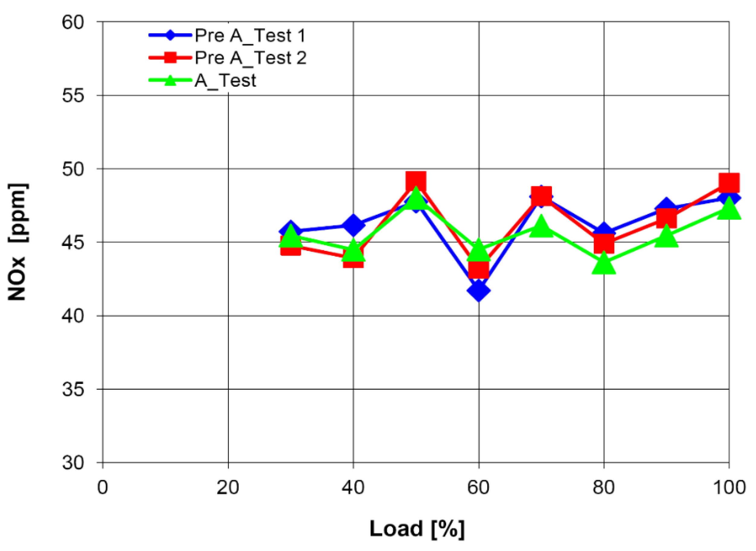
3.2.1. NOx Emission Characteristics

Figure 9 shows the NOx emission characteristics in response to the engine load fluctuations. NOx emissions must comply with environmental regulations. Experiments were performed in triplicate (once per day) under identical conditions, and these experiments have been denoted hereafter as Pre A_Test1, Pre A_Test2, and A_Test, for each consecutive day.
As shown in Figure 9, the target of <50 ppm NOx emission was satisfied; this was the emission control value at overall load. The NOx emissions were ~44–48 ppm, corresponding to 0.85 g/kWh. This value is ~9.4% of the IMO Tier II standard of the International Maritime Organization and also satisfies Tier III regulations. This implies that for the dedicated gas engines, NOx emission regulations can be satisfied without special post-treatment devices such as SCR (selective catalytic reduction) and EGR (exhaust gas recirculation). Meanwhile, when NOx emissions increase, thermal efficiency is improved. Therefore, if the excessive margin of NOx emission in some loads is reduced, some improvement in thermal efficiency can be expected.

3.2.2. Thermal Efficiency Characteristics

Figure 10 depicts the engine thermal efficiency according to the engine load. Thermal efficiency has a direct impact on fuel cost reduction and is an important factor in reducing CO2 emissions.
The engine thermal efficiency increased continuously as the engine load was increased, and the thermal efficiency was ~45.04% at 100% load, satisfying the development goal established for this study. In the case of a diesel engine, the maximum thermal efficiency is typically achieved at ~75–85% load. However, the thermal efficiency of the developed gas engine continued to increase beyond this load. This is because the ignition timing was set to be the same at overall load to improve the engine stability and maintain NOx emissions below 50 ppm.
In addition, fuel consumption, which is the reciprocal of thermal efficiency, was 170 g/kWh. This value is ~87% of 195 g/kWh, which is the fuel consumption of a typical diesel engine. This clearly indicates that the gas engine was effective in reducing fuel costs.
The effectiveness of the gas engine in reducing greenhouse gas emissions was also assessed. Figure 10 shows the CO2 emissions according to engine load fluctuations.
Unlike other regulated substances such as NOx and HCs, CO2 regulation is subject to total quantity regulation and is absolutely affected by thermal efficiency. As shown in Figure 11, CO2 emissions decreased continuously as the thermal efficiency increased with the increasing load. At 100% load, CO2 emissions were ~460 g/kWh, which is ~75% of the emissions of diesel engines of the same class. This observation indicated that gas engines are advantageous in responding to greenhouse gas regulations. In contrast, the rate of reduction in CO2 emissions exceeded the rate of improvement in thermal efficiency, which is because of the fact that gas fuel contains less carbon than diesel.
Lean combustion is an essential factor to achieve high efficiency and low NOx performance. Figure 12 depicts the excess air rate according to the load fluctuation.
The excess air ratio is expressed as the ratio of the actual air–fuel ratio to the theoretical air–fuel ratio, defined as lean combustion if the value is >1 and rich combustion if it is <1. Figure 12 reveals that lean combustion was achieved with an overall excess air ratio of >1.8, and an ultra-lean combustion of >2.0 was implemented in the high-load region (>80% load). The excess air rate also tended to increase continuously as the load increased for the same reason as the trend of increasing thermal efficiency.

3.2.3. Mean Effective Pressure

Figure 13 depicts the indicated mean effective pressure and brake mean effective pressure according to the engine load fluctuations. This figure indicates that the brake mean effective pressure achieved the development goal of 2.1 MPa at 100% load and delivers an engine output of 1.6 MW. The friction mean effective pressure, which is the difference between the indicated mean effective pressure and the brake mean effective pressure, was ~0.3 MPa and tends to be larger. This implies that the thermal efficiency of the developed gas engine can be further improved.
In contrast, the brake mean effective pressure of 2.1 MPa of the central gas mixer-type gas engine was quite high, and it can be concluded that the risk of knocking was significant.

4. Conclusions

The results of this study indicate that the development of the 1.6 MW independent gas engine model was completed successfully. The following conclusions can be drawn from the study:
  • A 1.6 MW dedicated gas engine was developed based on a diesel engine with bore 220, stroke 300. The developed gas engine had a precombustion chamber and exhibited excellent performance—2.1 MPa brake mean effective pressure at 1000 rpm and 50 ppm NOx emissions under 15% O2. In particular, it demonstrated excellent fuel economy with a thermal efficiency of 45%; its carbon dioxide emissions were ~75% of those of diesel engines, enabling greenhouse gas reduction. These results indicated that suitably developed gas engines can provide a low-cost and energy-efficient alternative to diesel engines.
  • The maximum pressure in the combustion chamber was ~16.9 MPa, which satisfied the designed pressure limits of the piston; the maximum pressure deviation between the cylinders was ~0.2–0.4 MPa, which was acceptable in accordance with engine stability.
  • Ultra-lean combustion with an excess air ratio of 2.0 or higher was implemented to achieve the target thermal efficiency.
  • The dedicated gas engine development goals of NOx emissions, thermal efficiency, and brake mean effective pressure were effectively achieved, and the values are as follows:
    • NOx emissions: 50 ppm or less at 15% O2.
    • Thermal efficiency: 45.04% at 50 ppm NOx.
    • Brake mean effective pressure: 2.1 MPa.
  • Specifically, NOx and CO2 emissions were significantly reduced compared to diesel engines:
    • NOx emissions: 0.85 g/kWh (~9.4% of IMO Tier II emissions).
    • CO2 emissions: 460 g/kWh (~75% of diesel engine emissions).
These results indicated that an appropriately designed gas engine can be a feasible alternative to a diesel engine, with a relatively lower cost and reduced greenhouse gas emissions.

Author Contributions

Conceptualisation, K.N.; Methodology, K.N.; Investigation, K.N.; Data Curation, K.N.; Writing—Original Draft Preparation, C.L.; Writing—Review and Editing, C.L. All authors have read and agreed to the published version of the manuscript.

Funding

This work was supported by the National Research Foundation of Korea (NRF) grant funded by the Korean government (MSIT). (No. 2021R1A2C1007789).

Institutional Review Board Statement

Not applicable.

Informed Consent Statement

Not applicable.

Data Availability Statement

Not applicable.

Conflicts of Interest

The authors declare no conflict of interest.

References

  1. Okamoto, K. Development of a 350 kW High-Efficiency (over 43%) Lean Burn Gas Engine for Co-Generation Systems. In Proceedings of the 24th CIMAC Congress, Kyoto, Japan, 7–11 June 2004. [Google Scholar]
  2. Tanaka, K. Development of Lean Burn Miller Cycle Gas Engine. In Proceedings of the 24th CIMAC Congress, Kyoto, Japan, 7–11 June 2004. [Google Scholar]
  3. Kalam, M.A.; Masjuki, H.H.; Maleque, M.A.; Amalina, M.A.; Abdesselam, H.; Mahlia, T.M.I.; Aslam, M.U.; Varman, M. Power improvement of a modified natural gas engine. In Proceedings of the 1st Conference & Exhibition on Natural Gas for Vehicles (ANGVA 2005), Kuala Lumpur, Malaysia, 26–28 July 2005. [Google Scholar]
  4. Klimkiewicz, D.; Teodorczyk, A. An experimental study of SI engine combustion system with direct methane injection. In Proceedings of the Third European combustion meeting ECM, Crete, Greece, 11–13 April 2007. [Google Scholar]
  5. Evans, R.L.; Blaszczyk, J. A compartive study of the performance and exhaust emissions of a spark ignition engine fuelled by natural gas and gasoline. Proc. Inst. Mech. Eng. Part D J. Automob. Eng. 1996, 211, 39–47. [Google Scholar] [CrossRef]
  6. Miller, R.H. Supercharging and internal cooling cycle for high output. Trans. ASME 1947, 69, 453–457. [Google Scholar]
  7. Al-Sarkhi, A.; Jaber, J.; Probert, S. Efficiency of a Miller engine. Appl. Energy 2006, 83, 343–351. [Google Scholar] [CrossRef]
  8. Zhao, Y.; Chen, J. Performance analysis of an irreversible Miller heat engine and its optimum criteria. Appl. Therm. Eng. 2007, 27, 2051–2058. [Google Scholar] [CrossRef]
  9. Endo, H.; Tanaka, K.; Kakuhama, Y.; Goda, Y.; Fujiwaka, T.; Nishigaki, M. Development of the lean burn Miller cycle gas engine. In Proceedings of the 5th International Symposium on Diagnostics and Modeling of Combustion in Internal Combustion Engines (COMODIA 2001), Nagoya, Janpan, 1–4 July 2001. [Google Scholar]
  10. Gheorghiu, V.; Ueberschar, D. Enhancement potential of the thermal conversion efficiency of ICE cycles especially for use in hybrid vehicles. In Proceedings of the 5th International Conference on Heat Transfer, Fluid Mechanics and Thermodynamics (HEFEAT2007), Sun City, South Africa, 1–4 July 2007. [Google Scholar]
  11. Wang, Y.; Ruxton, T. An experimental investigation of NOx emission reduction from automotive engine using the Miller cycle. In Proceedings of the ASME 2004 Fall Technical Conference, Long Beach, CA, USA, 24–27 October 2004. [Google Scholar]
  12. Wang, Y.; Lin, L.; Roskilly, A.P.; Zeng, S.; Huang, J.; He, Y.; Huang, X.; Huang, H.; Wei, H.; Li, S.; et al. An analytic study of applying Miller cycle to reduce NOx emission from petrol engine. Appl. Therm. Eng. 2007, 27, 1779–1789. [Google Scholar] [CrossRef] [Green Version]
  13. Heywood, J.B. Internal Combustion Engine Fundamentals; McGraw-Hill Inc.: New York, NY, USA, 1988. [Google Scholar]
  14. Branyon, D.; Simpson, D. Miller Cycle Application to the Scuderi Split Cycle Engine (by Downsizing the Compressor Cylinder); SAE Technical Paper 2012-01-0419; SAE International: Warrendale, PA, USA, 2012. [Google Scholar] [CrossRef]
  15. Wu, C.; Puzinauskas, P.V.; Tsai, J.S. Performance analysis and optimization of a supercharged Miller cycle Otto engine. Appl. Therm. Eng. 2003, 23, 511–521. [Google Scholar] [CrossRef]
  16. Hatamura, K.; Hayakawa, M.; Goto, T.; Hitomi, M. A study of the improvement effect of Miller-cycle on mean effective pressure limit for high-pressure supercharged gasoline engines. JSAE Rev. 1997, 18, 101–106. [Google Scholar] [CrossRef]
  17. Martins, J.J.G.; Uzuneanu, K.; Ribeiro, B.S.; Jasasky, O. Thermodynamic Analysis of an Over-Expanded Engine. SAE Trans. 2004, 113, 476–490. [Google Scholar]
  18. Al-Sarkhi, A.; Akash, B.A.; Jaber, J.O.; Mohsen, M.S.; Abu-Nada, E. Efficiency of Miller engine at maximum power density. Int. Commun. Heat Mass Transf. 2002, 29, 1159–1167. [Google Scholar] [CrossRef]
  19. Ebrahimi, R. Thermodynamic modeling of performance of a Miller cycle with engine speed and variable specific heat ratio of working fluid. Comput. Math. Appl. 2011, 62, 2169–2176. [Google Scholar] [CrossRef] [Green Version]
  20. Mikalsen, R.; Wang, Y.; Roskilly, A. A comparison of Miller and Otto cycle natural gas engines for small scale CHP applications. Appl. Energy 2009, 86, 922–927. [Google Scholar] [CrossRef] [Green Version]
  21. Anderson, M.K.; Assanis, D.N.; Filipi, Z.S. First and second law analyses of a naturalaspirated, Miller cycle, SI engine with late intake valve closure. SAE Trans. 1998, 107, 1355–1370. [Google Scholar]
  22. Kesgin, U. Efficiency improvement and NOx emission reduction potentials of two-stage turbocharged Miller cycle for stationary natural gas engines. Int. J.Energy Res. 2005, 29, 189–216. [Google Scholar] [CrossRef]
  23. Chen, L.; Lin, J.; Sun, F.; Wu, C. Efficiency of an Atkinson engine at maximum power density. Energy Convers. Manag. 1998, 39, 337–341. [Google Scholar] [CrossRef]
  24. Gonca, G.; Hocaoglu, M.F. Performance Analysis and Simulation of a Diesel-Miller Cycle (DiMC) Engine. Arab J Sci Eng 2019, 44, 5811–5824. [Google Scholar] [CrossRef]
  25. Sahin, B.; Kesgin, U.; Kodal, A.; Vardar, N. Performance optimization of a new combined power cycle based on power density analysis of the dual cycle. Energy Convers. Manag. 2002, 43, 2019–2031. [Google Scholar] [CrossRef]
  26. Benajes, J.; Molina, S.; Martín, J.; Novella, R. Effect of advancing the closing angle of the intake valves on diffusion-controlled combustion in a HD diesel engine. Appl. Therm. Eng. 2009, 29, 1947–1954. [Google Scholar] [CrossRef] [Green Version]
  27. Martins, M.E.S.; Lanzanova, T.D. Full-load Miller cycle with ethanol and EGR: Potential benefits and challenges. Appl. Therm. Eng. 2015, 90, 274–285. [Google Scholar] [CrossRef]
  28. Lin, J.C.; Hou, S.S. Performance analysis of an air-standard Miller cycle with considerations of heat loss as a percentage of fuel’s energy, friction and variable specific heats of working fluid. Int. J.Therm. Sci. 2008, 47, 182–191. [Google Scholar] [CrossRef]
  29. Ge, Y.; Chen, L.; Sun, F.; Wu, C. Effects of heat transfer and variable specific heats of working fluid on performance of a Miller cycle. Int. J. Ambient. Energy 2005, 26, 203–214. [Google Scholar] [CrossRef]
  30. Gonca, G.; Sahin, B.; Ust, Y. Performance maps for an air-standard irreversible DualeMiller cycle (DMC) with late inlet valve closing (LIVC) version. Energy 2013, 54, 285–290. [Google Scholar] [CrossRef]
  31. Gonca, G.; Sahin, B.; Parlak, A.; Ust, Y.; Ayhan, V.; Cesur, I.; Boru, B. The effects of steam injection on the performance and emission parameters of a Miller cycle diesel engine. Energy 2014, 78, 266–275. [Google Scholar] [CrossRef]
  32. Rinaldini, C.A.; Mattarelli, E.; Golovitchev, V.I. Potential of the Miller cycle on a HSDI diesel automotive engine. Appl. Energy 2013, 112, 102–119. [Google Scholar] [CrossRef]
  33. Dexter, S.G.; Ennemoser, C. Fire Not Misfire in Pre-Chamber Gas Engines. In Proceedings of the 21st CIMAC Congress, Interlaken, Switzerland, 15–18 May 1995. [Google Scholar]
  34. Herdin, G.R.; Gruber, F.; Henkel, W.; Fahringer, A. The New High Efficiency 1.5 MW Engine of Jenbacher AG, High Efficiency Concept–HEC. In Proceedings of the 23rd CIMAC Congress, Hamburg, Germany, 7–10 May 2001; pp. 966–975. [Google Scholar]
  35. Takemoto, T. Development of High Efficiency Gas Engine Improvement of Knocking Limit by Optimized Engine System. In Proceedings of the 24th CIMAC Congress, Kyoto, Japan, 7–11 June 2004. [Google Scholar]
  36. Herdin, G.R.; Gruber, F. Miller Cycle-Efficiency Potentials for Gas Engines. In Proceedings of the 24th CIMAC congress, Kyoto, Japan, 7–11 June 2004. [Google Scholar]
  37. Kondo, M. Development of the 1000 kW-Class Gas Engine (MD20G). In Proceedings of the 25th CIMAC Congress, Vienna, Austria, 21–24 May 2007. [Google Scholar]
  38. Edwards, K.D.; Wagner, R.M.; Daw, C.S. Adaptive Control for Extending the Effective Lean Limit in a Spark-Ignition Engine Model. In Proceedings of the 24th CIMAC Congress, Kyoto, Japan, 7–11 June 2004. [Google Scholar]
  39. Murakami, S.; Baufeld, T. Current Status and Future Strategies of Gas Engine Development. In Proceedings of the CIMAC 2013, Shanghai, China, 13–17 May 2013. [Google Scholar]
Figure 1. Comparison of Otto and Miller air-standard cycles. (a) Air-standard Otto cycle; (b) Air-standard Miller cycle.
Sustainability 13 04097 g001
Figure 2. Miller cam profile.
Sustainability 13 04097 g002
Figure 3. Photograph of the gas engine developed in this study.
Sustainability 13 04097 g003
Figure 4. Cylinder head and precombustion chamber.
Sustainability 13 04097 g004
Figure 5. Schematic of the gas supply system.
Sustainability 13 04097 g005
Figure 6. Engine control system.
Sustainability 13 04097 g006
Figure 7. In-cylinder pressure versus crank angle in the combustion chamber.
Sustainability 13 04097 g007
Figure 8. Ensemble-averaged pressure and pressure deviation between cylinders versus engine load.
Sustainability 13 04097 g008
Figure 9. NOx emission rate versus engine load.
Sustainability 13 04097 g009
Figure 10. Thermal efficiency versus engine load.
Sustainability 13 04097 g010
Figure 11. Brake-specific CO2 versus engine load.
Sustainability 13 04097 g011
Figure 12. Excess air ratio versus engine load.
Sustainability 13 04097 g012
Figure 13. Indicated mean effective pressure and friction mean effective pressure versus engine load of the developed gas engine.
Sustainability 13 04097 g013
Table 1. Development targets and operating conditions of the gas engine.
PhaseTarget
Power1.6 MW
Brake mean effective pressure2.1 MPa
Thermal efficiency45% (acc. to ISO 3046-1)
NOx≤50 ppm at 15% O2
Ambient temperature25 °C
Ambient pressure0.1 MPa
Intake depression5.0 kPa
Charged air temperature40 °C
Exhaust back pressure4.0 kPa
Table 2. Specifications of the gas engine developed in this study.
PhaseSpecification
Bore/stroke200/300
Arrangement of cylinder8 in-line
Engine speed1000 rpm
Compression ratio12.0
FuelNatural gas
Fuel admissionCentral gas mixer
Engine speed controlThrottle valve
IgnitionSpark plug with PC
Table 3. Gas characteristics for the engine performance test.
PhaseUnitQuality
CH4 composition%>90
Lower heating valueMJ/Nm339.33
Densitykg/m30.7976
Stoichiometric ratio-16.87
Molecular weightkg/kmol17.77
Methane number-73
Gas supply pressure, (g)MPa>0.55
Publisher’s Note: MDPI stays neutral with regard to jurisdictional claims in published maps and institutional affiliations.

