Article

Compaction Procedures and Associated Environmental Impacts Analysis for Application of Steel Slag in Road Base Layer

1
State Key Laboratory of Silicate Materials for Architectures, Wuhan University of Technology, Wuhan 430070, China
2
State Key Laboratory of High-Performance Civil Engineering Materials, Sobute New Materials Co., Ltd., Nanjing 211103, China
3
Department of Civil and Environmental Engineering, Norwegian University of Science and Technology, 7491 Trondheim, Norway
*
Author to whom correspondence should be addressed.
Sustainability 2021, 13(8), 4396; https://doi.org/10.3390/su13084396
Submission received: 25 March 2021 / Revised: 11 April 2021 / Accepted: 13 April 2021 / Published: 15 April 2021
(This article belongs to the Special Issue Recycled Materials and Infrastructure Sustainability)

Abstract

:
In recent years, recycling steel slag is receiving growing interest in the road base layer construction field due to its role in alleviating land occupation and resource shortages. However, the mixture compaction and its environmental impact on practical construction sites remain unclear, which may hinder the application of steel slags in road layers. This study investigates the pavement construction of the ‘Baotou-Maoming’ motorway, located in Inner Mongolia, China, analyzing the compaction procedures and assessing the environmental impacts caused by the road base layer containing steel slag. Firstly, mechanical properties and texture appearances of the steel slag aggregates are characterized. Afterwards, the comparative assessments for steel slag and andesite layers compaction are quantified from equivalent CO2 emission and energy consumption aspects, respectively. The results show that the steel slag has a better surface texture than the natural aggregates; physical properties including compactness, flatness and compressive strength comply with the requirements for applying steel slag to a hydraulically bound mixture. Compared to the base layer using andesite aggregates, the compaction vibration period of the course containing steel slags should be reduced to achieve a proper density due to the “hard-to-hard” effect that occurs between the adjacent steel slag particles. Consequently, the additional energy and the equivalent CO2 are generated at 2.67 MJ/m3 and 0.20 kg/m3, respectively.

1. Introduction

Road networks have been rapidly developing in recent decades, which is strictly linked to modernization and urbanization. The United States Department of Transportation announced that the national highway system was composed of over 164,000 miles of highway in 2011 [1], while the length increased to 223,257 miles in 2017 [2]. At the end of 2018, the total length of national highways in China reached 4.85 million kilometers [3], reaching 5.01 million kilometers in 2019 [4]. In many studies, the rapid expansion and improvement of new road constructions can be seen, especially in developing countries [5]. Nevertheless, the sustainability of road construction and development is increasingly questioned due to various environmental issues, such as the large consumptions of natural aggregate resources.
With the exploration of solid waste recycling, steel slag has become a potential material to be increasingly developed and used as a manufactured aggregate for civil engineering applications [6]. Generally, steel slag is a by-product of the steelmaking industry. In the steelmaking furnace, various raw materials (iron ore, steel scrap, pig iron, limestone and so forth) are refined at a high temperature, and the refined mixture is divided into two incompatible liquid phases by controlling the temperature. One part is molten steel, and the other part is steel slag. Currently, there are five different types of steel slags generated by different sources: blast furnace slag, basic oxygen furnace slag, electric arc furnace slag, ladle furnace slag and stainless steel slag [7].
Previously, steel slag was stacked on abandoned ground for long periods of time [8]. Since, several researchers have found that steel slag powder can be used as filler to promote the mechanical properties of cement concrete [9]. Studies have increasingly investigated the alternative utilization of steel slags in road construction. In recent years, concerns about the environmental impacts of utilizing steel slags in road construction have been constantly raised. The primary benefit of steel slag recycling is to reduce the land used by steel waste stockpiling; moreover, the application of manufactured alternatives greatly relieves the shortage of natural aggregates worldwide [10]. According to an investigation on natural aggregate extraction, the energy consumption for specific aggregate production ranges from 25.2 to 32.2 MJ/ton [11]. Furthermore, numerous explosives and chemical emulsions are employed during aggregate extraction processes, generating massive amounts of air pollutants and heavy metals. On the contrary, steel slag is a by-product of the steel making industry, and so theoretically brings about limited environmental burdens during its production process.
Considerable concerns have been raised in road construction studies regarding the release of potentially hazardous components by steel slag aggregates. Ivana et al. analyzed the potential adverse impacts of steel slag leachate. The results indicated that the leachates from two tested steel slags showed weak alkalinity, and the concentrations of toxic elements (heavy metals) are far below the limit, posing little risk to the ecological environment [12]. Moustakas et al. investigated the leaching impacts of air-cooled and water-cooled slags. The results considered the European official decision (2003/33/EC) and leaching procedures test, and confirmed the safety of slag utilization [13]. Sasmita et al. collected slag leachates from three steelmaking manufacturers and assessed their contents of heavy metals. The results showed that toxic elements (As, Cd, Se and V) had not been leached, and other heavy metals were below the warning value [14]. Xie et al. evaluated the utilization possibility of steel slag from both laboratory and in-place perspectives. The results showed that the leachate fulfilled most of the global environmental laws and regulations [15]. Hence, steel slag can be considered to be a sustainable material for recycling in road construction, in terms of the economy and environmental protection.
A report from the European Slag Association showed that 43% of steel slag arisings were employed in road construction in 2012 [16]. On the contrary, notwithstanding the meaningful increase in the generation of steel slag in China, 29.5% of steel slag is ineffectively utilized, over 300 million tons of which cannot be reasonably treated and recycled [8]. Currently, most studies focus on the performance effect of employing steel slag in pavement constructions and on the overall environmental impacts. Monshi et al. proved that steel slag concrete had better compressive strength than original Portland cement concrete [17]. Maslehuddin et al. proved that some physical and mechanical properties (i.e., resistance to reinforcement corrosion and compressive strength) of steel slag concrete were better than limestone concrete [18]. Srinivasa et al. found an improvement in cementing properties when using quenched slag products in hydraulically bound mixtures [19]. Altun et al. reported that applying steel slag as an aggregate can obtain an acceptable physical and mechanical performance [20]. The existing literature indicates that steel slag cement mixtures can be well applied to the road base layer.
From the perspective of Life Cycle Assessments (LCA), substantial environmental benefits can be obtained by applying steel slag aggregate [21]. Saade et al. investigated whether using steel slag can significantly contribute to the reduction of Greenhouse Gas (GHG) emissions, global warming and terrestrial ecotoxicity [22]. Pasetto conducted the case study and employed PaLATE (a widely used LCA tool) to compare the feasibility of steel slag and natural mineral aggregates in asphalt pavement construction, stating that approximately 39.77 TJ of energy and 2653 tons of CO2 can be reduced during the material production process [23]. Václavík et al. replaced natural aggregates with steel slag in cement concrete and investigated associated environmental impacts using an LCA. The results showed that steel slag aggregate can diminish 7% of environmental burdens [24]. Anastasiou et al. considered the sustainability of utilizing industrial by-products (fly ash and steel slag) in cement mixtures. The results found that cement clinker content is critical for GHG emissions, and the transport distances of steel slag aggregate could strikingly affect the environmental burdens in the material production stage [25].
The majority of research explores the potentials of steel slag in laboratories, while the specific construction procedures related to practical pavement engineering are seldom researched and reported, which may hinder the application of steel slag in pavement construction. To address the research gap, this study has investigated a stretch of motorway located in Inner Mongolia, China. The surface’s micro-texture and the composition of the manufactured aggregates were analyzed in the laboratory before application in the field. The effect on basic road performance was analyzed for the different compaction procedures of a hydraulically bound mixture containing steel slag aggregate, compared with a reference material andesite, while the base course compaction procedure was thoroughly investigated in the field by means of three types of compaction plants. Eventually, the associated equivalent CO2 emissions and energy consumptions were analyzed to assess the overall environmental impacts when steel slag was applied into the road base layer.

2. Materials and Methods for the Case Study

This study has considered the construction of a hydraulically bound mixture for a road base layer along the “Baotou-Maoming” motorway located in Inner Mongolia, China. The base course was designed with a width of 7 m and a thickness of 20 cm.

2.1. Physical Properties of Steel Slag and Andesite
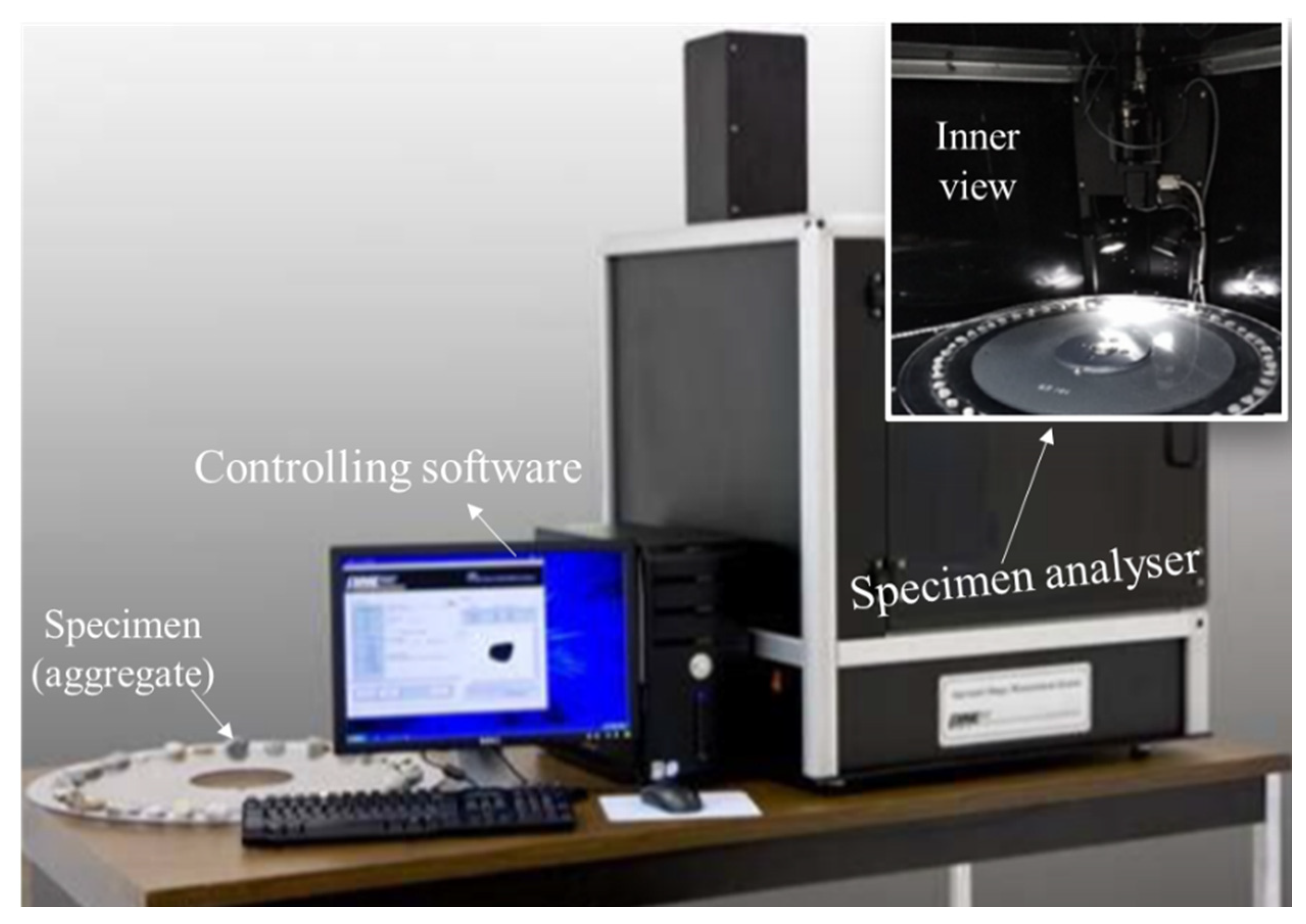
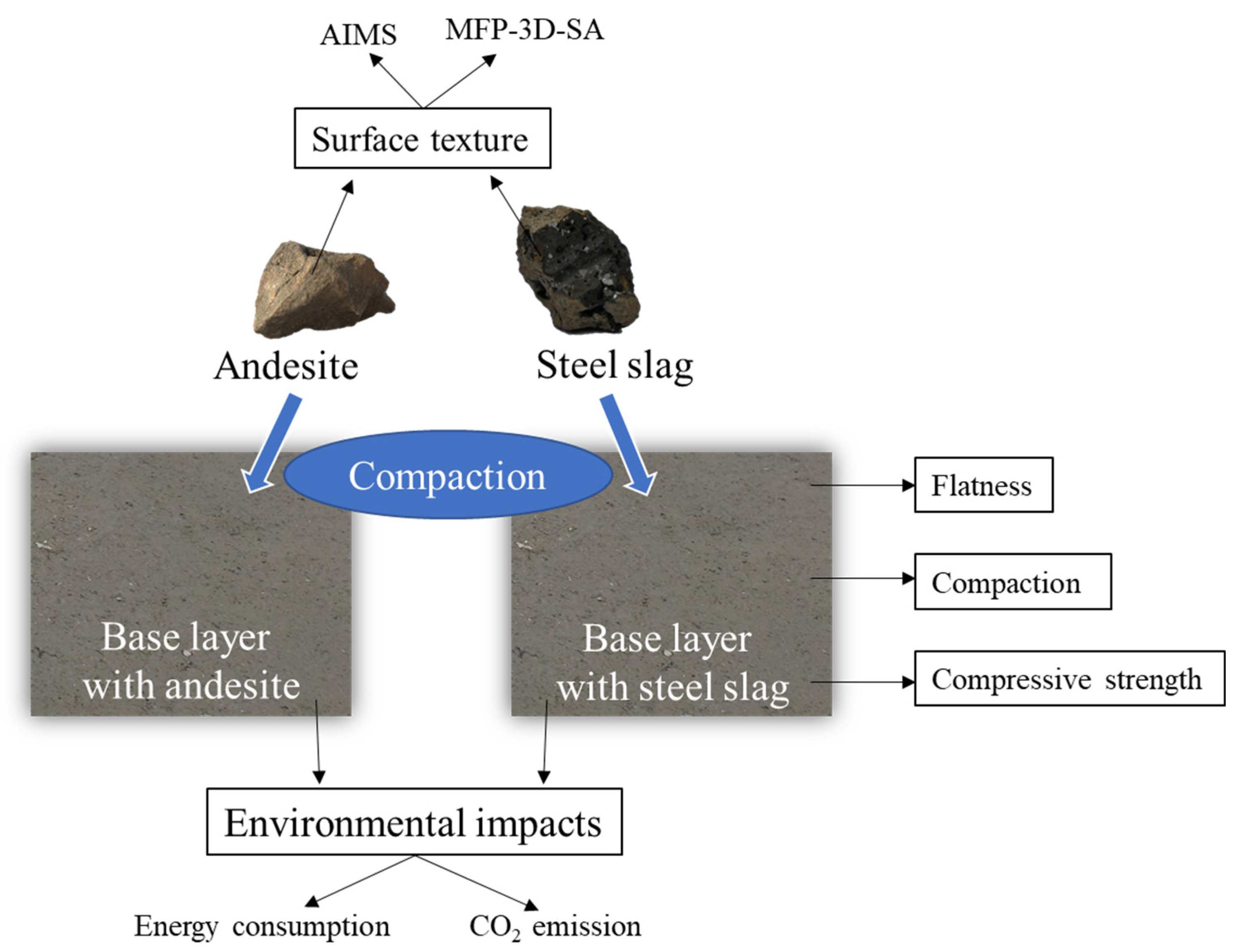
The steel slags, obtained from Lucheng and supplied by the Baotou City Steel Slag Road Performance and Engineering Application Research Center, underwent a three-stage process to make them into usable manufactured aggregates: initially, the tailings (blast furnace slags) generated by the steel industry were placed into a hot furnace and cooled down; afterwards, the steel tailings were aged by climate conditions, aiming to decrease the expansion and shrinkage effects; then, the stable slags were crushed, and sieved for appropriate sizes according to the actual requirements.
Lucheng steel slags and andesite were used in the hydraulically bound mixture as coarse and fine aggregates (the size designating the limit between coarse and fine dimensions was considered equal to 4.75 mm), respectively [26]. For comparison, the study also investigated a traditional base layer which only comprised of andesite aggregates for the hydraulically bound mixture. Portland cement with a compressive strength grade of 32.5 MPa was employed as binder (Table 1). The physical and mechanical properties of the steel slags were investigated according to the Chinese standard of Testing Methods of Aggregate for Highway Engineering (JTG E42-2005) [27] and displayed in Table 2. In addition, the content of free calcium oxide (f-CaO), usually regarded as a major issue due to the phenomenon of swelling in water [28,29], is listed in Table 2, which is below the suggested limit [30].
The physical properties of the aggregates are closely related to the load capacity of the hydraulically bound mixture, as well as to the adhesion with the cement binder [31]. The surfaces of both the Lucheng steel slag and andesite were investigated by means of an Aggregates Image Measurement System (AIMS) device (Figure 1). The Texture Index (TI) is commonly used for quantifying the aggregate’s surface texture. TI values, obtained as reported in Equation (1), range from 0 to 1000: a bigger TI indicates a rougher surface, leading to a higher shear resistance and load capacity of the mixture [32,33]. Twenty aggregates with particle sizes comprised between 10 mm and 16 mm were investigated and given a TI value.
T I = 1 3 n i = 1 3 j = 1 N ( D i , j ( x , y ) ) 2 ,
where n is the decomposition level during measurement, N is the total number of coefficients in the detected image, the i value is 1, 2 or 3 based on the image analysis dimension (horizontal, vertical, and diagonal), the j value corresponds to the wavelet coefficient index, D is the compiled decomposition function, and x and y locate the coefficients in a transformed domain.
Four different TI ranges were used to describe the surface roughness, namely 0–200 (low), 200–500 (moderate), 500–750 (high) and 750–1000 (extreme). Figure 2 shows the cumulative TI percentage of Lucheng steel slag and andesite: most of the natural aggregates belong to a moderate level, while the largest part of the manufactured steel slag aggregates lies within a high level. The average TI values for Lucheng steel slag and andesite were 566.8 and 437.5, respectively. A greater TI value of an aggregate can obtain a stronger load capacity of the hydraulically bound mixture. Hence, Lucheng steel slag offers a better surface texture for cement workability.
Furthermore, this study employed a Mean Free Path-3 Dimensions-Scanning Atomic Force Probe (MFP-3D-SA) to investigate the microscopic characteristics of the aggregate interface. The fractal dimension was utilized to describe the irregularity of each point on the scanned surfaces, and the logarithmic curve of the incremental variable was adopted to analyze the slope and the shape of the aggregate interface. The width and depth of the image was 20 μm and the height was 2.5 μm. Figure 3a,b show the 3D microscopic texture of Lucheng steel slag and andesite, respectively. The obvious differences in structure and microscopic characteristics illustrated that the lighter color which appeared in Figure 3a accounts for a higher percentage, and its emulated structure also presents a greater angularity than Figure 3b. Therefore, compared to manufactured aggregate, the surface texture of natural aggregate is more regular, indicating that the selected steel slag aggregate has better surface characteristics to prepare a hydraulically bound mixture.

2.2. Study Methods

Figure 4 illustrates the research diagram of this study. The surface textures of both of the base layers containing manufactured aggregates and natural aggregates were initially analyzed by means of an Aggregates Image Measurement System (AIMS) and a Mean Free Path-3 Dimensions-Scanning Atomic Force Probe (MFP-3D-SA). Successively, the following in-service properties were assessed: surface flatness, layer compaction and compressive strength of hydraulically bound mixture specimens. Eventually, the research quantified the equivalent CO2 emissions and the energy consumption related to the compaction operations.

3. Results and Discussion

3.1. Mechanical Properties of Base Layer

Steel slag was used for the coarse aggregate fractions (size bigger than 4.75 mm) and andesite for the fine aggregate fractions during the production of the hydraulically bound mixture. Table 3 presents the gradation design of the aggregates. The percentage of added cement was 5% by mass, and water content applied here was 4.6%.

3.1.1. Optimization of Compaction Procedure

In this investigated case, three different types of compactors were used in the field for the base layer containing steel slags: Single Steel Wheel Roller (SSWR), Double Steel Wheel Roller (DSWR) and Pneumatic Tired Roller (PTR). Table 4 presents the specifications of the used compactors.
The density achieved by each compaction procedure was evaluated using sand (ϕ 15 mm, loose density 1.38 g/cm3) according to JTGE60-2008 [34]. The first investigated compaction procedure (C1) was conducted on andesite aggregates, composed of three vibration cycles (weak, strong, weak) for a total length of 60 m back and forth performed by a SSWR; successively, cycles two and one were accomplished by PTR and DSWR (static mode), respectively. After this compaction procedure, we measured the compactness (K) in two different locations with the maximum densities at 93.0% and 96.2%. These results did not fulfil the practical requirements (98.0%) based on the code of JTGE60-2008 [34].
Specifically, under the strong vibration, the surface of the steel slag mixture underwent deformation, meanwhile, under high frequency vibration, the “hard-to-hard” effect occurred between the adjacent steel slag particles, resulting in the loosening of the compacted mixture. The surface containing hard steel slag particles made the compaction process more sensitive than andesite. Hence, the compaction procedure (C1) could obtain a good compaction for andesite, but failed to achieve the required effects for steel slag. Figure 5 shows the “hard-to-hard” phenomenon for steel slag.
Based on the results obtained for the first compaction procedure, an optimized compaction procedure (C2) was proposed to alleviate the “hard-to-hard” effect. The operations were performed according to the following sequence: one SSWR cycle applying static pressure forth and strong vibration back; then, three SSWR cycles (static pressure) and two PTR cycles; eventually, one more SSWR cycle (static pressure). Following this procedure, the average compactness achieved 95.8%. Although the code requirements were not met again, the higher values proved the beneficial effect generated by the weaker vibration.
Eventually, a third compaction procedure (C3) was investigated to increase the base layer density: one cycle with a SSWR (static pressure) plus three weak cycles with a SSWR (vibration); then, four cycles with a PTR; finally, one cycle completed with a DSWR (static pressure). The compactness values of C3 measured in three different locations (L1, L2, L3) were now equal to 97.8%, 98.8% and 99.1%, respectively (Table 5). The average value was 98.6%, which lies within the code threshold. The surfaces of the base layer compacted according to the three procedures (C1, C2, C3) are displayed in Figure 6. The detrimental effect generated by the weak and the strong vibration is clearly visible in terms of loose surface; on the other hand, a proper density was achieved due to reduced vibration frequency and an increased number of cycles with static pressure.

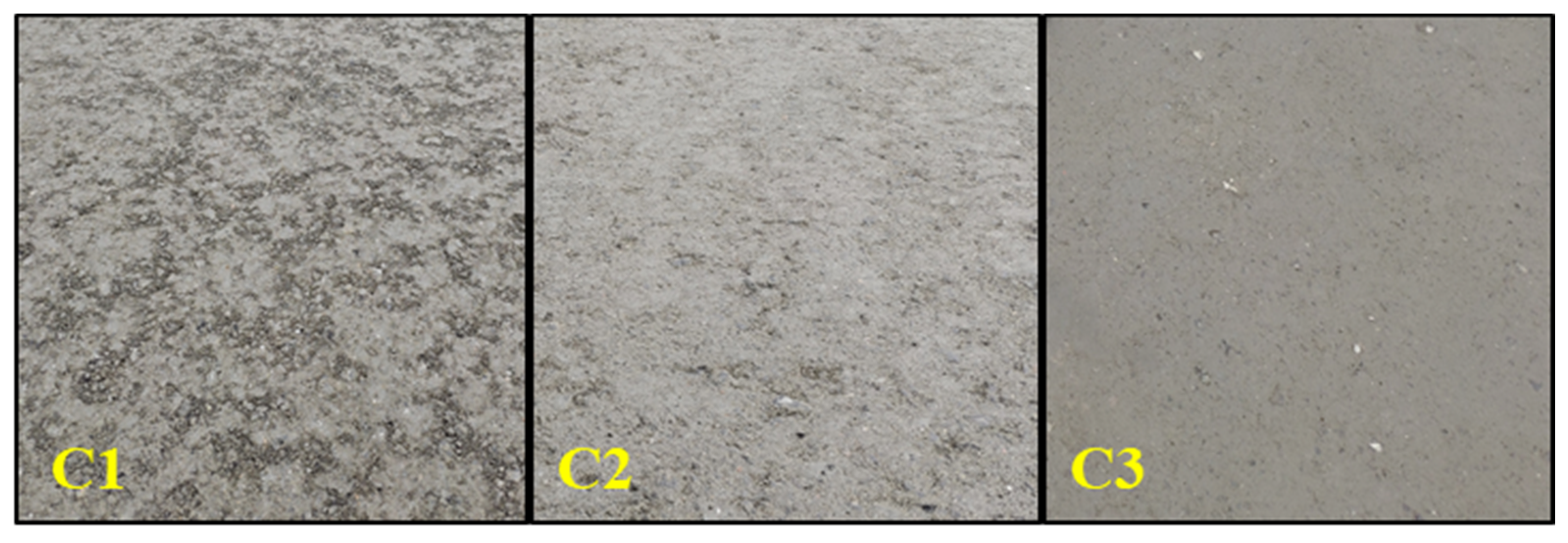
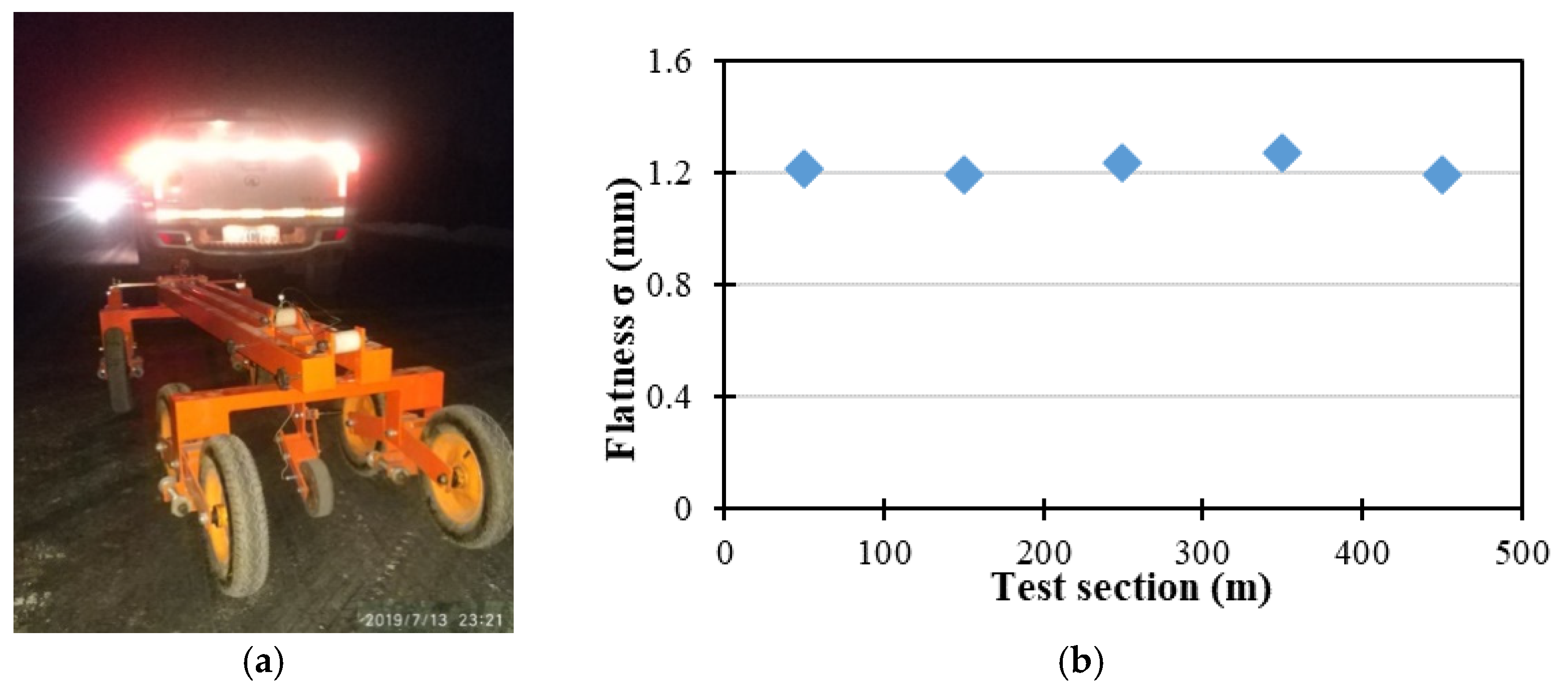
3.1.2. Surface Flatness

The flatness (σ) of the base layer was analyzed after compaction by means of a Continuous Flatness Meter (CFM). The device wheel was equipped to measure the surface flatness for all of the test sections [35]. The device automatically recorded the vertical displacement deviations every 10 cm (unit measurement interval), and the final flatness index was evaluated every 100 m (Equation (2)). The CFM was towed for the entire base layer length (500 m) at the speed (V) of 6.8 km/h.
σ i =   d i 2 (   d i ) 2 / N N 1 ,
where σi is the standard deviation of flatness for 100 m (mm), di represents the displacement deviation for the unit measurement interval (mm), and N is the total number of recorded data.
The flatness (σ) of all of the five test sections exceeded 1.2 mm, and the average value was 1.3 mm (Figure 7); therefore, the standard requirements were fulfilled [36].

3.1.3. Hydraulically Bound Mixture Strength

The compressive strength of the hydraulically bound mixture containing steel slag was evaluated with 26 cylindrical samples, which were randomly divided into two groups (A and B). All of the specimens were molded with a diameter and height of 150 mm using the universal testing machine WE-1000. The samples were stored at room temperature for six days and soaked for one day. Eventually, the unconfined compressive strength was assessed using the universal testing machine WE-300B according to the Chinese standard code JTG E51 [36,37]. The compressive strength varied between 8 MPa and 11 MPa as showed in Figure 8 and Table 6.
The limited variability between the two groups indicated that the compressive strength results were relatively stable. The compressive strength of the two groups of samples was higher than 9 MPa within the 95% confidence interval. Compared to the natural aggregate mixture (8.0 MPa within the 95% confidence interval), the steel slag mixture can achieve a higher strength, indicating that steel slag mixture is able to properly resist the compressive stresses generated by road traffic loads [38].

3.2. Environmental Impacts

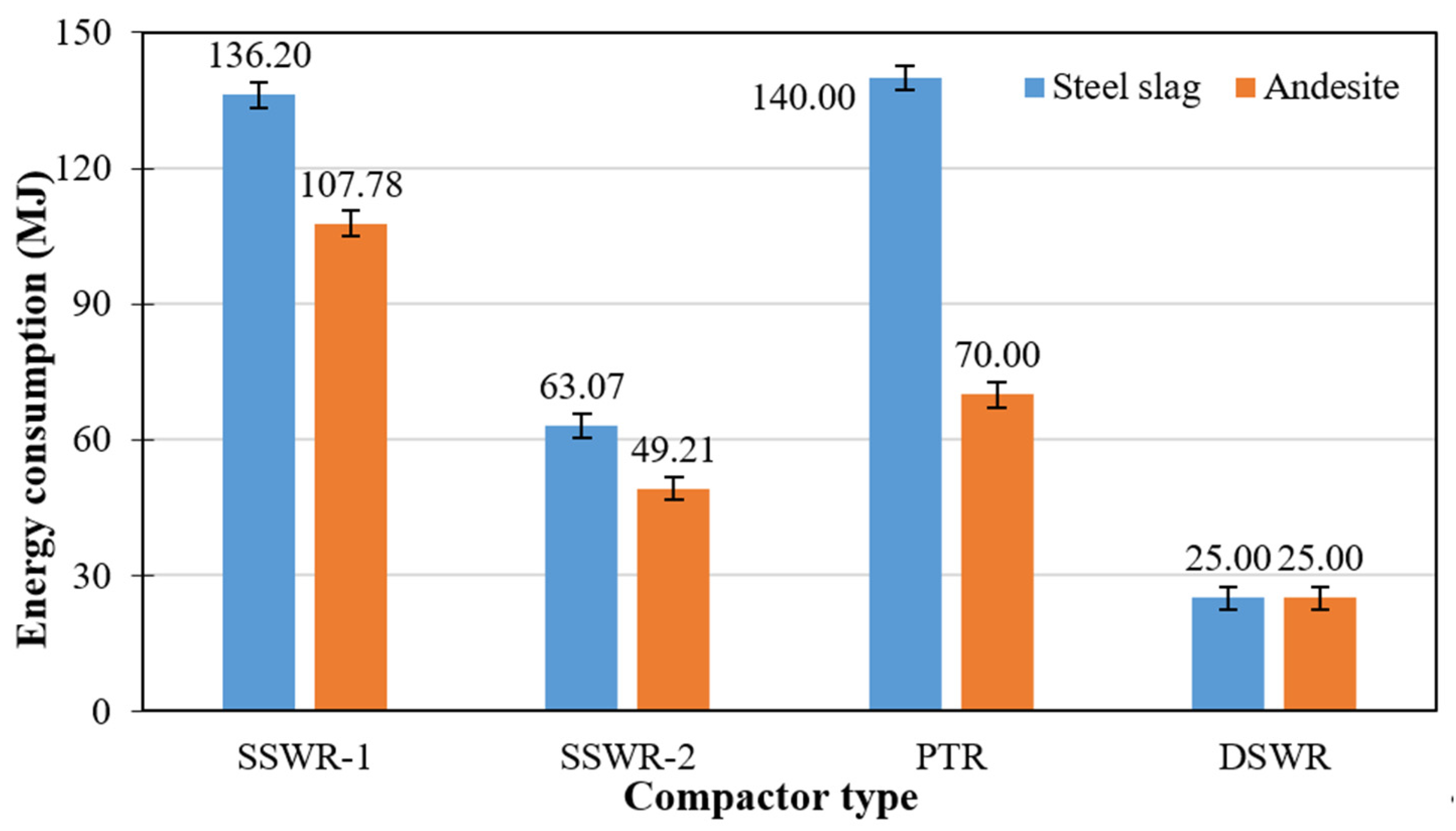
3.2.1. Energy Consumption

This study investigated the diesel consumption of the four different roller compactors, and the functional unit was assumed to be the road base layer with a length of 30 m. The assessment of energy consumption and equivalent CO2 emissions referred to the applied compaction procedures (C1 for andesite mixture and C3 for steel slag mixture) previously reported in Section 3.1.1.
Equations (3) and (4) express the energy consumption associated to the vibration process and driving process, respectively. Equation (5) specifies the total energy consumption.
E 1 = F × A × f × L × n × D v × d ,
E 2 = P × D × L × n v × d ,
E = E 1 + E 2 α ,
where E1 is the energy consumption for the vibration process (kJ), F represents the vibration force (kN), A is the vibration amplitude (mm), f indicates the vibration frequency (Hz), L is the working length in one cycle (m), n represents the number of compactors, D is the working width of the base layer (m), v indicates the driving speed (m/s) and d is the compacting width (m). E2 is the energy consumption for driving process (kJ) and P is the operation power (kW). E represents the total energy consumption during compaction (kJ) and α is the energy utilization rate of diesel compactors (%).
Two types of SSWRs were adopted for compaction, namely KS225HD-2 (SSWR-1) and CLG 620H (SSWR-2). SSWRs consume a different amount of diesel when they operate according to strong (S) or weak (W) vibration mode (Table 7): the fuel consumption was calculated based on the number of SSWRs and the working time. The compacting width for DSWR and PTR was 2.1 m and 2.7 m, respectively. Based on past work [39,40], the average thermodynamic efficiency α for diesel consumption was assumed to be 40%.
Figure 9 reports that the total energy consumption for the compaction of the functional unit containing steel slag aggregate or andesite aggregate is 364.27 MJ or 251.99 MJ, respectively. Considering the base layer containing natural aggregate, the highest energy amount was consumed by SSWR-1 (107.78 MJ); regarding the hydraulically bound mixture containing Lucheng steel slag, the PTR entailed the biggest energy consumption (140 MJ) because the vibration period of the SSWR was shortened and the static pressure of the PTR was increased.
On one hand, the use of steel slag as a manufactured aggregate in pavement construction is beneficial given the increasing shortage of natural aggregates; on the other hand, the compaction on site would require more energy than the amount demanded for a traditional base layer to ensure appropriate density and surface flatness. Compared to the compaction of the andesite base course, the application of steel slag generated an additional 2.67 MJ/m3 energy consumption.

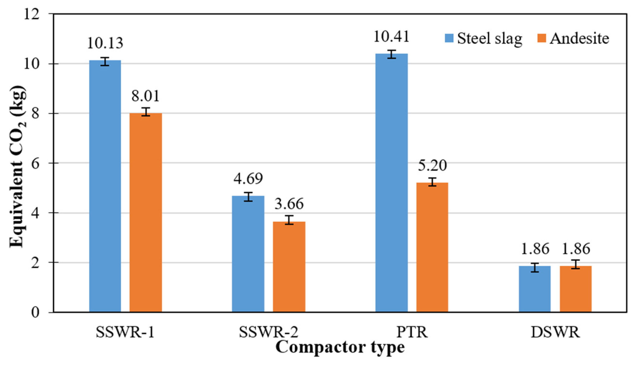
3.2.2. Equivalent CO2 Emission

This study referred to the China Statistical Yearbook [41] and the Chinese Life Cycle Database (CLCD) [42] to retrieve data related to the diesel supplied during compaction. The equivalent CO2 emission was calculated with Equation (6).
G = E × G 0 E 0
where G indicates the equivalent CO2 emission (kg), E represents the total energy consumption during compaction (kJ), G0 is the standard diesel emission factor (kg/kg) and E0 is the standard diesel calorific rate (MJ/kg).
Figure 10 displays the equivalent CO2 emissions related to the four types of compactors. Overall, the compaction of the functional unit containing manufactured aggregates or natural aggregates engendered the release of 27.08 kg and 18.73 kg equivalent CO2, respectively. Moreover, the PTR generated the largest quantity of equivalent CO2 for steel slag mixture (10.41 kg), while the SSWR-1 was the major GHG contributor for andesite mixture (8.01 kg). In our investigated case, compacting steel slag mixture caused higher equivalent CO2 emissions than andesite mixture by 0.20 kg/m3.
According to the elaborated results in Figure 9 and Figure 10, steel slag and andesite mixtures presented the same ratio distribution of energy consumption and GHG emissions. To assess the influence of the four compactors, their occupied percentages of GHG emission are illustrated in Figure 11 and Figure 12 for steel slag and andesite base layers, respectively. SSWRs played a significative role in the compaction of steel slag (55%) and andesite (62%) mixtures, followed by PTRs and DSWRs; the PTR had undertaken a higher proportion of work in steel slag mixture, by 10%, because its static pressure alleviated the “hard-to-hard” effect. Furthermore, compactor’s driving operation accounts for most of the diesel consumption.
From a life cycle perspective, most studies have reported that using manufactured aggregates such as steel slag in lieu of natural aggregates can positively contribute to the reduction of environmental depletion [43,44]. However, the calculated results obtained from this investigated case show that when only focusing on the environmental impacts in compaction procedures, steel slag aggregates cause higher energy consumption and GHG emissions than andesite. Hence, reducing the environmental impacts of compaction can distinctly strengthen the road sustainability by employing manufactured aggregates instead of natural aggregates.

4. Conclusions

Steel slag is a solid waste which can be conveniently recycled in civil engineering applications. This study characterized the use of steel slag in a hydraulically bound mixture for road base layers. Furthermore, an additional traditional base layer containing andesite (a natural aggregate) was also investigated for comparison. The compaction procedures of the base layers have been thoroughly investigated in the field by means of four different compactors; furthermore, surface flatness, layer density and the compressive strength of the hydraulically bound mixture were also evaluated. Eventually, the environmental impacts of the compaction operations were assessed.
Based on the performed analyses, results, and discussion, the following conclusions can be drawn:
(1)
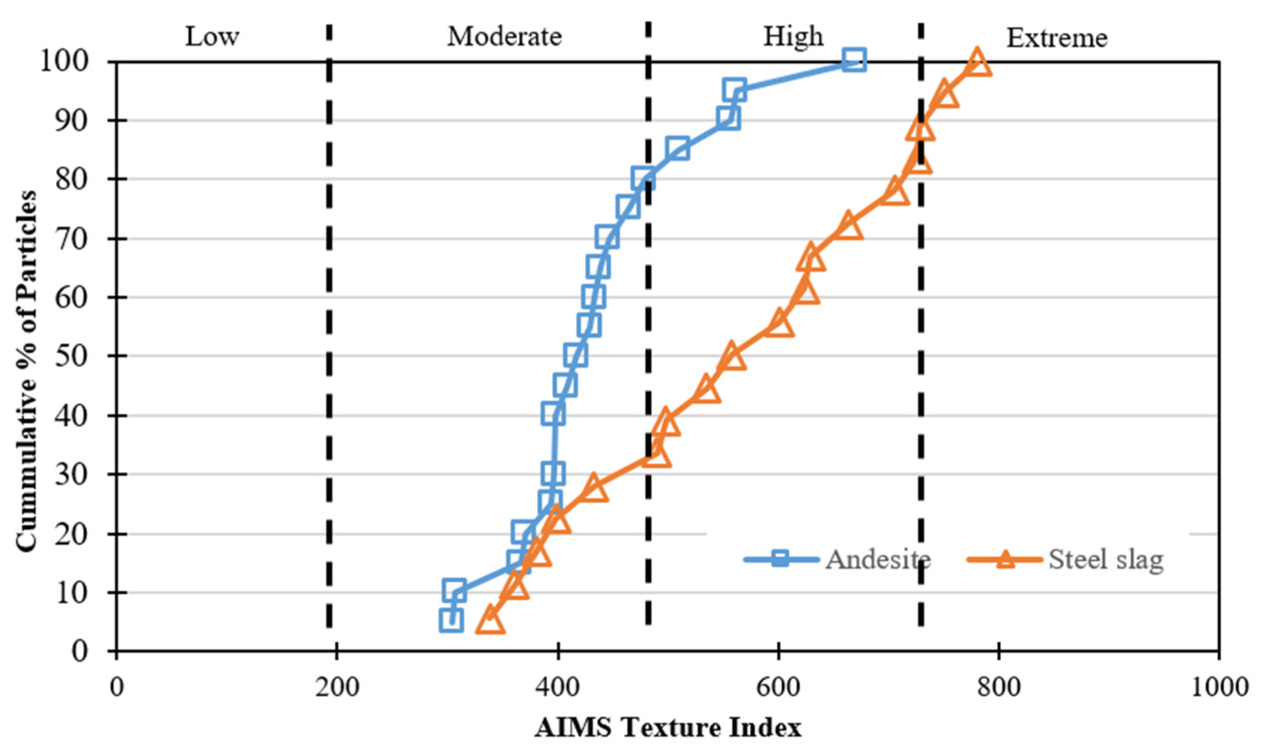
Steel slag aggregate offers better roughness and surface micro-morphology properties than andesite aggregate in this investigated case.
(2)
The base layer containing steel slag aggregate fulfils the road construction requirements specified by the standard code, namely compactness, surface flatness and compressive strength of the hydraulically bound mixture.
(3)
Strong vibrations should be avoided or reduced during compaction to mitigate the adverse “hard-to-hard” effect between adjacent steel slag particles; the static pressure exerted by the rolling compactors should be increased.
(4)
Compared to the andesite base course, the base layer containing steel slag entails a higher diesel consumption used by the compactors: an additional 2.67 MJ/m3 of energy and 0.20 kg/m3 equivalent CO2 emissions were generated.

Author Contributions

B.G.: Conceptualization, Formal analysis, Investigation; C.Y.: Conceptualization, Investigation, Writing—Original Draft; Y.Z.: Methodology, Writing—Review & Editing, Investigation; F.W.: Methodology, Writing—Review & Editing, Supervision; X.Z.: Writing—Review & Editing, Resources, Visualization; D.M.B.: Writing—Review & Editing, Visualization, Supervision; S.W.: Methodology, Supervision, Project administration. All authors have read and agreed to the published version of the manuscript.

Funding

This research was funded by the National Natural Science Foundation of China (No. 71961137010 and No. 51778515), the Ministry of Science and Technology National Key R&D Plan (No. 2017YFE0111600) and the State Key Laboratory of Silicate Materials for Architectures (Wuhan University of Technology, No. SYSJJ2019-20). Finally, this study was supported by the Technological Innovation Major Project of Hubei Province (2019AEE023).

Institutional Review Board Statement

Not applicable.

Informed Consent Statement

Informed consent was obtained from all subjects involved in the study.

Data Availability Statement

Some or all data, models, or code generated or used during the study.

Conflicts of Interest

The authors declare no conflict of interest.

References

  1. U.S. Department of Transportation. Highway Finance Data Collection. Our Nation’s Highways: 2011; Federal Highway Administration: Washington, DC, USA, 2014.
  2. Improving America’s Transportation Infrastructure: The Road Forward; U.S. Department of Transportation: Washington, DC, USA, 2017.
  3. Development Statistics Bulletin of Transportation Industry in 2018; Ministry of Transport of China: Beijing, China, 2019.
  4. Statistical Bulletin of Transportation Industry Development in 2019; Ministry of Transport of China: Beijing, China, 2020.
  5. Laurance, W.F.; Clements, G.R.; Sloan, S.; O’Connell, C.S.; Mueller, N.D.; Goosem, M.; Venter, O.; Edwards, D.P.; Phalan, B.; Balmford, A.; et al. A global strategy for road building. Nat. Cell Biol. 2014, 513, 229–232. [Google Scholar] [CrossRef]
  6. Gao, D.; Wang, F.-P.; Wang, Y.-T.; Zeng, Y.-N. Sustainable utilization of steel slag from traditional industry and agriculture to catalysis. Sustainability 2020, 12, 9295. [Google Scholar] [CrossRef]
  7. Skaf, M.; Manso, J.M.; Aragón, Á.; Fuente-Alonso, J.A.; Ortega-López, V. EAF slag in asphalt mixes: A brief review of its possible re-use. Resour. Conserv. Recycl. 2017, 120, 176–185. [Google Scholar] [CrossRef]
  8. Guo, J.; Bao, Y.; Wang, M. Steel slag in China: Treatment, recycling, and management. Waste Manag. 2018, 78, 318–330. [Google Scholar] [CrossRef]
  9. Yi, H.; Xu, G.; Cheng, H.; Wang, J.; Wan, Y.; Chen, H. An overview of utilization of steel slag. Procedia Environ. Sci. 2012, 16, 791–801. [Google Scholar] [CrossRef] [Green Version]
  10. Horii, K.; Kato, T.; Sugahara, K.; Tsutsumi, N.; Kitano, Y. Overview of iron/steel slag application and development of new utilization technologies. Nippon Steel Sumitomo Tech. Rep. 2015, 109, 5–11. [Google Scholar]
  11. Jullien, A.; Proust, C.; Martaud, T.; Rayssac, E.; Ropert, C. Variability in the environmental impacts of aggregate production. Resour. Conserv. Recycl. 2012, 62, 1–13. [Google Scholar] [CrossRef] [Green Version]
  12. Barišić, I.; Grubeša, I.N.; Kutuzović, B.H. Multidisciplinary approach to the environmental impact of steel slag reused in road construction. Road Mater. Pavement Des. 2017, 18, 897–912. [Google Scholar] [CrossRef]
  13. Moustakas, K.; Mavropoulos, A.; Katsou, E.; Haralambous, K.-J.; Loizidou, M. Leaching properties of slag generated by a gasification/vitrification unit: The role of pH, particle size, contact time and cooling method used. J. Hazard. Mater. 2012, 207–208, 44–50. [Google Scholar] [CrossRef] [PubMed]
  14. Chand, S.; Paul, B.; Kumar, M. Short-term leaching study of heavy metals from LD slag of important steel industries in Eastern India. J. Mater. Cycles Waste Manag. 2016, 19, 851–862. [Google Scholar] [CrossRef]
  15. Xie, J.; Wu, S.; Zhang, L.; Xiao, Y.; Ding, W. Evaluation the deleterious potential and heating characteristics of basic oxygen furnace slag based on laboratory and in-place investigation during large-scale reutilization. J. Clean. Prod. 2016, 133, 78–87. [Google Scholar] [CrossRef]
  16. Euroslag & Eurofer. Position Paper on the Status of Ferrous Slag complying with the Waste Framework Directive (Articles 5/6) and the REACH Regulation; European Slag Association: Duisburg, Germany, 2012. [Google Scholar]
  17. Monshi, A.; Asgarani, M.K. Producing Portland cement from iron and steel slags and limestone. Cem. Concr. Res. 1999, 29, 1373–1377. [Google Scholar] [CrossRef]
  18. Maslehuddin, M.; Sharif, A.M.; Shameem, M.; Ibrahim, M.; Barry, M. Comparison of properties of steel slag and crushed limestone aggregate concretes. Constr. Build. Mater. 2003, 17, 105–112. [Google Scholar] [CrossRef]
  19. Reddy, A.S.; Pradhan, R.; Chandra, S. Utilization of Basic Oxygen Furnace (BOF) slag in the production of a hydraulic cement binder. Int. J. Miner. Process. 2006, 79, 98–105. [Google Scholar] [CrossRef]
  20. Altun, I.A.; Yilmaz, I. Study on steel furnace slags with high MgO as additive in Portland cement. Cem. Concr. Res. 2002, 32, 1247–1249. [Google Scholar] [CrossRef]
  21. Lee, K.-M.; Park, P.-J. Estimation of the environmental credit for the recycling of granulated blast furnace slag based on LCA. Resour. Conserv. Recycl. 2005, 44, 139–151. [Google Scholar] [CrossRef]
  22. Saade, M.R.M.; da Silva, M.G.; Gomes, V. Appropriateness of environmental impact distribution methods to model blast furnace slag recycling in cement making. Resour. Conserv. Recycl. 2015, 99, 40–47. [Google Scholar] [CrossRef]
  23. Pasetto, M.; Pasquini, E.; Giacomello, G.; Baliello, A. Life-cycle assessment of road pavements containing marginal materials: Comparative analysis based on a real case study. In Pavement Life-Cycle Assessment; CRC Press: London, UK, 2017. [Google Scholar]
  24. Václavík, V.; Ondová, M.; Dvorský, T.; Eštoková, A.; Fabiánová, M.; Gola, L. Sustainability potential evaluation of concrete with steel slag aggregates by the LCA method. Sustainability 2020, 12, 9873. [Google Scholar] [CrossRef]
  25. Anastasiou, E.; Liapis, A.; Papayianni, I. Comparative life cycle assessment of concrete road pavements using industrial by-products as alternative materials. Resour. Conserv. Recycl. 2015, 101, 1–8. [Google Scholar] [CrossRef]
  26. Wang, F.; Hoff, I.; Yang, F.; Wu, S.; Xie, J.; Li, N.; Zhang, L. Comparative assessments for environmental impacts from three advanced asphalt pavement construction cases. J. Clean. Prod. 2021, 297, 126659. [Google Scholar] [CrossRef]
  27. Ministry of Transport of China. Test Methods of Aggregate for Highway Engineering (JTG E42–2005); China Communications Press: Beijing, China, 2005.
  28. Kandhal, P.S.; Hoffman, G.L. Evaluation of steel slag fine aggregate in hot-mix asphalt mixtures. Transp. Res. Rec. J. Transp. Res. Board 1997, 1583, 28–36. [Google Scholar] [CrossRef]
  29. Frías, M.; De Rojas, M.S.; Uría, A. Study of the instability of black slags from electric arc furnace steel industry. Mater. Constr. 2002, 52, 79–83. [Google Scholar] [CrossRef] [Green Version]
  30. Wang, Q.; Wang, D.; Zhuang, S. The soundness of steel slag with different free CaO and MgO contents. Constr. Build. Mater. 2017, 151, 138–146. [Google Scholar] [CrossRef]
  31. Nallathambi, P.; Karihaloo, B.L.; Heaton, B.S. Effect of specimen and crack sizes, water/cement ratio and coarse aggregate texture upon fracture toughness of concrete. Mag. Concr. Res. 1984, 36, 227–236. [Google Scholar] [CrossRef]
  32. Xiao, Y.; Wang, F.; Cui, P.; Lei, L.; Lin, J.; Yi, M. Evaluation of fine aggregate morphology by image method and its effect on skid-resistance of micro-surfacing. Materials 2018, 11, 920. [Google Scholar] [CrossRef] [PubMed] [Green Version]
  33. Cui, P.; Xiao, Y.; Yan, B.; Li, M.; Wu, S. Morphological characteristics of aggregates and their influence on the performance of asphalt mixture. Constr. Build. Mater. 2018, 186, 303–312. [Google Scholar] [CrossRef]
  34. Ministry of Transport of China. Code for Field Test of Highway Subgrade and Pavement (JTGE 60-2008); China Communications Press: Beijing, China, 2008.
  35. Winter, M. The Determination of the Acceptability of Selected Fragmenting Materials for Earthworks Compaction: Prepared for National Roads Directorate, Scottish Office Development Department; Thomas Telford: Lomdon, UK, 1999. [Google Scholar]
  36. Shen, J.; Li, F.; Lv, G. JTJ059-95 Highway Subgrade Pavement Field Test Procedures; People’s Communications Press: Beijing, China, 1995. [Google Scholar]
  37. Ministry of Transport of China. Test Methods of Materials Stabilized with Inorganic Binders for Highway Engineering (JTG E51–2009); China Communications Press: Beijing, China, 2009.
  38. Huang, Y.H. Pavement Analysis and Design; Pearson: London, UK, 2004. [Google Scholar]
  39. Edwards, C.F.; Teh, K.-Y.; Miller, S.L. Low exergy loss chemical engines. In Global Climate & Energy Project; Stanford University: Stanford, CA, USA, 2006. [Google Scholar]
  40. Tebbe, P. DIESEL ENGINE. 2015. Available online: https://cset.mnsu.edu/engagethermo/components_diesel.html (accessed on 1 January 2021).
  41. China Statistical Yearbook; National Bureau of Statistics of China: Beijing, China, 2012.
  42. Chinese Life Cycle Database; IKE Environmental Technology Sichuan University: Chengdu, China, 2012.
  43. Leal, D.; Winter, M.G.; Seddon, R.; Nettleton, I.M. A comparative life cycle assessment of innovative highway slope repair techniques. Transp. Geotech. 2020, 22, 100322. [Google Scholar] [CrossRef]
  44. Gomes Correia, A.; Winter, M.G.; Puppala, A.J. A review of sustainable approaches in transport infrastructure geotechnics. Transp. Geotech. 2016, 7, 21–28. [Google Scholar] [CrossRef] [Green Version]
Figure 1. Aggregates Image Measurement System (AIMS) device.
Sustainability 13 04396 g001
Figure 2. Texture Index (TI) of Lucheng steel slag aggregate and andesite aggregate.
Sustainability 13 04396 g002
Figure 3. 3D microscopic texture interface for steel slag (a) and andesite (b).
Sustainability 13 04396 g003
Figure 4. Research diagram of the hydraulically bound mixture for the road base layer.
Sustainability 13 04396 g004
Figure 5. Steel slag “hard-to-hard” effect in compaction. The particles are initially relatively close to each other (a), deformation takes place under external strong vibration (b) and an elastic recovery expansion occurs successively (c). Eventually, the displacement of the particles results in a macroscopic decrease in density (d).
Sustainability 13 04396 g005
Figure 6. Surface of base layer compacted according to the C1C3.
Sustainability 13 04396 g006
Figure 7. Flatness test device (a) and measurement results (b) for the base layer containing steel slag aggregates.
Sustainability 13 04396 g007
Figure 8. Compressive strengths for sample group A and B.
Sustainability 13 04396 g008
Figure 9. Energy consumption for the compactors used in the investigation.
Sustainability 13 04396 g009
Figure 10. Equivalent CO2 emissions for the compactors used in the investigation.
Sustainability 13 04396 g010
Figure 11. Equivalent CO2 emission composition related to the compaction of the steel slag base layer.
Sustainability 13 04396 g011
Figure 12. Equivalent CO2 emission composition related to the compaction of the andesite base layer.
Sustainability 13 04396 g012
Table 1. Fundamental properties of the cement used in the road base layer.
PropertyCharacteristicResultRequirementStandard
Fineness80 μm (%)1.0<10GB/T1345-2005
Setting timeInitial (min)259≥180GB/T1346-2011
Final (min)420≥360,
≤600
Flexural strength3d (MPa)4.4≥2.5GBT17671-1999
28d (MPa)7.5≥5.5
Compressive strength3d (MPa)18.5≥10.0
28d (MPa)38.4≥32.5
Composition contentSO3 (%)2.34≤4.0GB/T176-2008
MgO (%)4.04≤6.0
Cl- (%)0.01≤0.06
Ignition loss (%)1.15≤5.0
Table 2. Fundamental properties of Lucheng steel slag.
PropertySizeResultRequirementStandard
Crushing value (%)-10.3≤26T0316
Los Angeles abrasion value (%)-8.5≤28T0317
Flake particles content (%)4.75–9.5 mm10.1≤12T0312
≥9.5 mm6.7≤12
Weak particles content (%)-0.2≤3T0320
f-CaO content (%)10–16 mm2.42≤3YB140-2009
Table 3. Blending ratio for hydraulically bound mixture containing steel slag.
MaterialSteel SlagAndesite
Size (mm)19–26.56–199.5–164.75–9.50–4.75
Mass ratio (%)1316182231
Table 4. Roller compactors used for the base layer.
CompactorSSWRDSWRPTR
Wheel TypeSteelSteelRubber
ModelKS225HD-2CLG 620HKP306HBOMAG203
Vibration frequency,
max-min (Hz)
32/2832/28/50/40
Vibration force,
max-min (kN)
415/285400/210/0.69/0.29
Amplitude,
max-min (mm)
1.98/0.991.90/1.00/126/84
Power (kW)140132140100
Table 5. Compactness values for the final compaction procedure (C3) in three different locations.
LocationWet Density
ρ (g/cm3)
Moisture Content (%)Dry Density
ρd (g/cm3)
Compactness
K
L12.8755.52.72597.8
L22.9042.75398.8
L32.9142.76299.1
Table 6. Compressive strength of hydraulically bound mixture containing steel slag.
Sample GroupAB
Average strength (MPa)9.49.9
Standard deviation0.230.26
Coefficient of variation (%)2.442.57
95% confidence rate (MPa)9.09.5
Table 7. Compactor parameters according to strong (S) and weak (W) vibration modes.
CompactorForce
(kN)
Frequency
(Hz)
Amplitude
(mm)
Width
(m)
Speed
(m/s)
SSWR-1S412321.981.52
W285280.991.52
SSWR-2S400321.902.12
W210281.002.12
Publisher’s Note: MDPI stays neutral with regard to jurisdictional claims in published maps and institutional affiliations.

