Article

Jet Impingement Heat Transfer of Confined Single and Double Jets with Non-Newtonian Power Law Nanofluid under the Inclined Magnetic Field Effects for a Partly Curved Heated Wall

by
Fatih Selimefendigil
1,*,
Hakan F. Oztop
2 and
Ali J. Chamkha
3,4
1
Department of Mechanical Engineering, Celal Bayar University, 45140 Manisa, Turkey
2
Department of Mechanical Engineering, Technology Faculty, Fırat University, 23119 Elazığ, Turkey
3
Faculty of Engineering, Kuwait College of Science and Technology, Doha District 35001, Kuwait
4
Center of Excellence in Desalination Technology, King Abdulaziz University, P.O. Box 80200, Jeddah 21589, Saudi Arabia
*
Author to whom correspondence should be addressed.
Sustainability 2021, 13(9), 5086; https://doi.org/10.3390/su13095086
Submission received: 1 April 2021 / Revised: 21 April 2021 / Accepted: 27 April 2021 / Published: 1 May 2021
(This article belongs to the Special Issue Thermal Management in Energy Systems)

Abstract

:
Single and double impinging jets heat transfer of non-Newtonian power law nanofluid on a partly curved surface under the inclined magnetic field effects is analyzed with finite element method. The numerical work is performed for various values of Reynolds number (Re, between 100 and 300), Hartmann number (Ha, between 0 and 10), magnetic field inclination ( γ , between 0 and 90), curved wall aspect ratio ( A R , between 01. and 1.2), power law index (n, between 0.8 and 1.2), nanoparticle volume fraction ( ϕ , between 0 and 0.04) and particle size in nm ( d p , between 20 and 80). The amount of rise in average Nusselt (Nu) number with Re number depends upon the power law index while the discrepancy between the Newtonian fluid case becomes higher with higher values of power law indices. As compared to case with n = 1, discrepancy in the average Nu number are obtained as 38 % and 71.5% for cases with n = 0.8 and n = 1.2. The magnetic field strength and inclination can be used to control the size and number or vortices. As magnetic field is imposed at the higher strength, the average Nu reduces by about 26.6% and 7.5% for single and double jets with n greater than 1 while it increases by about 4.78% and 12.58% with n less than 1. The inclination of magnetic field also plays an important role on the amount of enhancement in the average Nu number for different n values. The aspect ratio of the curved wall affects the flow field slightly while the average Nu variation becomes 5%. Average Nu number increases with higher solid particle volume fraction and with smaller particle size. At the highest particle size, it is increased by about 14%. There is 7% variation in the average Nu number when cases with lowest and highest particle size are compared. Finally, convective heat transfer performance modeling with four inputs and one output is successfully obtained by using Adaptive Neuro-Fuzzy Interface System (ANFIS) which provides fast and accurate prediction results.

1. Introduction

Impinging jets play an important role in various heat transfer (HT) applications such as in textiles, solar energy, turbo machinery, microelectro-mechanical systems (MEMs), and many other systems. In solar applications, photovoltaic (PV) panel thermal management may be performed by using jet impingement (J-I) cooling while in food industry, convective drying performance can be increased with J-I due to the locally higher HT and mass transfer coefficients. In the applications with jet impinging HT, the interaction between the established flow recirculations, pressure gradients, thermal boundary layers and complex geometry will make the analysis very hard to treat it theoretically. Many theoretical, experimental and numerical simulation studies have been performed during the recent years to understand the flow physics and HT mechanisms with impinging jets. Maghrabie [1] extensively studied the latest advancements in the impinging jet HT with many installation geometries and modified jet configurations. Garimella [2] analyzed various impacts including geometric factors and velocity profiles for impinging jet HT for confined single and double J-I HT applications. Applications exist that considered the use of impinging jets for thermal management and performance enhancement of PV system [3,4,5,6]. Droplet jet cooling may be effective in liquid cooling [7].
The performance of impinging jets in convective HT applications may be improved by using different active and passive HT enhancement methods. In one of the offered methods for HT enhancement, nano-sized particles are used in the HT fluid. The nanofluid (NF) technology applications have been installed in many energy systems for HT enhancement, thermal management and applications vary from refrigeration to thermal energy storage [8,9,10,11,12,13,14,15]. During the recent years, many advanced modeling techniques have been developed to simulate the NF behavior in diverse thermal energy configurations [16,17,18,19,20]. In convective HT with impinging jets, NFs have also been considered in many studies [21,22,23,24]. In the experimental analysis of Li [25], using NFs (Cu-water) increased the HT coefficient by about 52% for submerged jets. Lv [26], experimentally explored the use of SiO 2 nanoparticles in water for single J-I HT up to solid volume fraction ( ϕ ) of 3%. Enhancement of convective HT coefficient by about 40% is achieved with Re number between 8000 to 13,000 at the highest ϕ value. In the review work of Mohammadpour and Lee [27], convective HT with J-I considering NFs have been presented for conventional and swirl type jets. Recent applications and future trends were mentioned with some of the challenges as in agglomeration of nanoparticles and pressure drop features. Many aspects of the NF may be considered such as particle shape, kinetics of nanoparticles agglomeration and non-Newtonian fluid behavior. Convective HT with non-Newtonian behavior of NF has been considered in many studies [28,29,30,31]. Transient free convective HT in a trapezoidal shaped cavity was considered in Ref. [32] by using non-Newtonian power law NF. Lower values of power law index were found to be effective on the HT enhancement. Kefayati [33] analyzed the convective HT and second law in a cavity with magnetic field (MF) effects considering non-Newtonian NF model. The entropy generation rate was found to be dependent upon the power law index. Even though, studies exist that consider the non-Newtonian behavior of fluid with J-I HT [34,35,36], there are a few studies that consider the impinging jet application with non-Newtonian NFs [37].
In the convective HT with impinging jets, MF effects have been considered in many studies [38,39]. There are applications wheres MF effects are present such as in flow control in molten steel in continuous casting process [40] or MF can be used for convective HT control. The advantageous of using NFs have been considered in many studies where MF effects are present. NFs have been used in several works under the impacts MF in HT applications of J-I systems [41,42,43]. The MF was shown to reduce the fluid motion but at the same time, the potentiality of suppressing the vortices established in the thermo-flow system and performance improvement were also shown in several other studies [44]. The application of NF with MF effects in HT applications for impinging jets provides more control options for thermal management and HT control. The jet impinging HT has also been considered for various effects of the impinging surface such as elasticity [45] and curvature [46,47,48,49].
In the present study, confined slot J-I HT of non-Newtonian power law NF for partly curved surface is analyzed. Even though NFs technology has been used in many impinging jet HT applications and even in some few studies MF effects were considered, non-Newtonian power law fluid effects considering nanoparticles for jet impinging curved target surface including impacts of MF has never been considered in the literature. Confined single jet and double-jet configurations are utilized. As many applications of J-I HT exist in diverse thermal engineering field, the outcomes of the present work will be helpful in the initial design and optimization of convective HT with impinging jet of non-Newtonian power law fluid with MF effects. In the first part, modeling aspects with computational fluid dynamics will be presented. The results will be presented in terms of flow and thermal patterns visualizations, Nu number variations considering various values of Re number, MF strength and inclination, power law index of non-Newtonian fluid, solid volume fraction/size of the particles and curvature ratio of the impinging wall. In the second part of the modeling, convective HT performance estimation by using adaptive neuro-fuzzy interface system (ANFIS) will be performed for various input parameters.

2. Mathematical Formulation

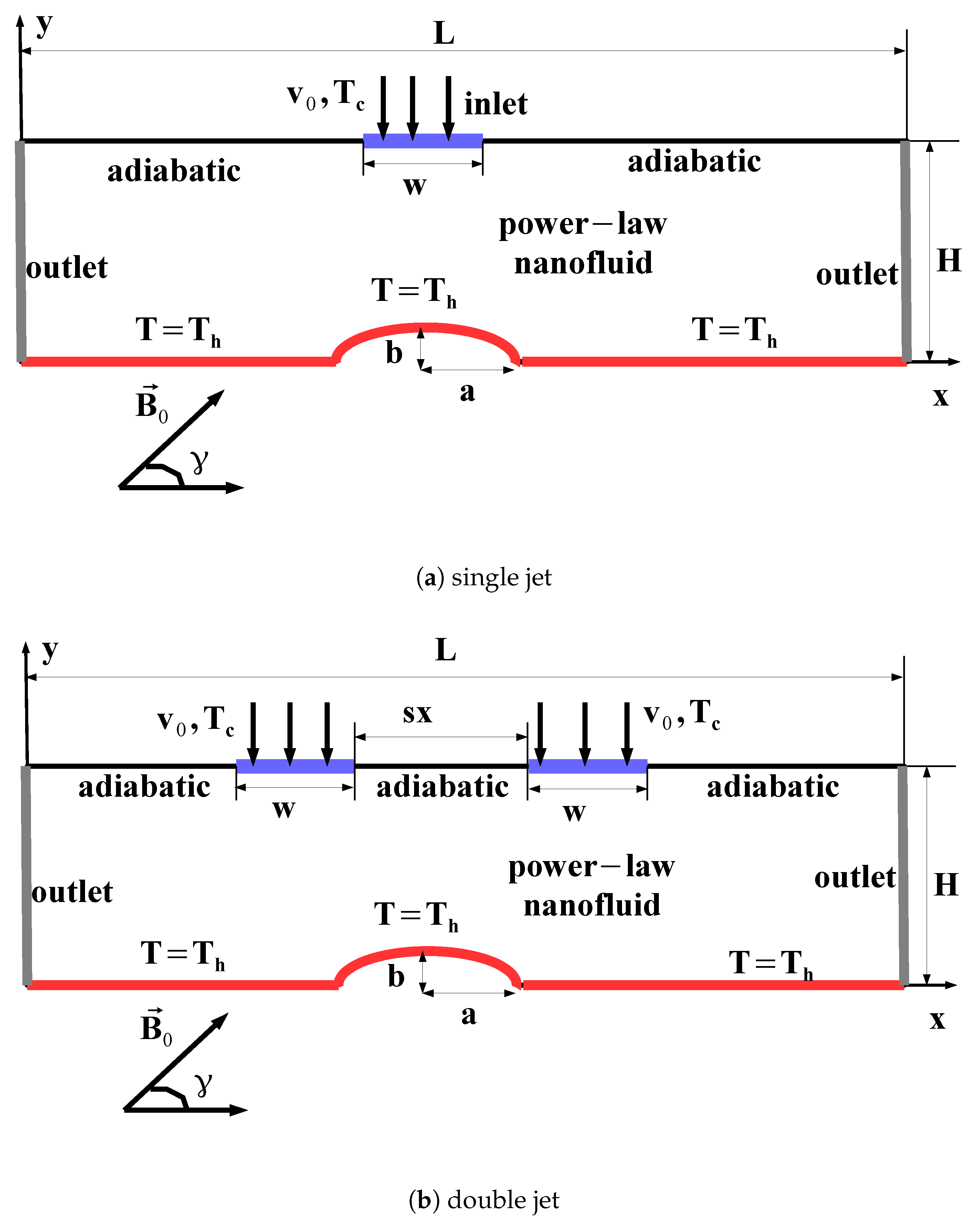
Confined single and double jet (SJ, DJ) configurations are schematically shown in Figure 1. The target impinging surface is partly curved with elliptic shape having radius of a and b in the axis. Cold fluid with jet velocity of v 0 and temperature of T c impinges the curved surface which is at constant temperature of T h . The separating distance between the jet inlet ant target plate is H while the width of rectangular slot is w and plate length is L. In the case of DJ configuration, the distance between jets is s x . A uniform MF with magnitude B 0 is used for SJ and DJ cases and it makes inclination of γ with horizontal axis. The natural convection effects with viscous dissipation are neglected. The induced MF effects, Joule heating and impacts of displacement currents are not considered.
Conservation equations (CEs) of mass, momentum and energy are given in the following for a 2D Cartesian coordinate system [33]:
u x + v y = 0
u u x + v u y = 1 ρ p x + 1 ρ τ x x x + τ x y y + σ B 0 2 ρ v sin ( γ ) cos ( γ ) u sin 2 ( γ )
u v x + v v y = 1 ρ p y + 1 ρ τ x y x + τ y y y σ B 0 2 ρ u sin ( γ ) cos ( γ ) v cos 2 ( γ )
u T x + v T y = α 2 T x 2 + 2 T y 2
In the above given equations MF strength and its inclination are given by B 0 and γ .
Shear stress τ is described as [50]:
τ = μ u + u T ,
with dynamic viscosity μ .
For a power law fluid, it is given as [50]:
τ = m | γ ˙ | n 1 γ ˙ ,
with m and n representing the consistency coefficient and power law index while γ ˙ is the shear rate. For a shear thinning (pseudoplastic) n < 1 while for shear-thickening (dilatant) fluid n > 1 and n = 1 represents a Newtonian fluid.
Boundary conditions (BCs) are given as:
  • At the jet inlet, temperature and velocity are uniform, u = 0 , v = v 0 , T = T c .
  • For the bottom plate, temperature is constant and no-slip BC is used, u = v = 0 , T = T h .
  • The top plate is adiabatic and no-slip BC is considered, u = v = 0 , T y = 0
  • At the side surfaces, x-direction gradients are set to zero, u x = 0 , v x = 0 , T x = 0
The relevant non-dimensional numbers are: Prandtl number (Pr), Reynolds number (Re) and Hartmann number (Ha) which are defined as in the following [33,51]:
Pr = c p m k u 0 H n 1 , Re = ρ H n ( u 0 ) 2 n m , Ha = B 0 H n + 1 σ m u 0 n 1 1 / 2 .
As the heat transfer fluid (HTF), alumina-water NF is used with thermophysical properties given in Table 1. Advanced correlations which are Corcione’s correlations are used for the alumina-water NF effective thermal conductivity ( k n f ) and viscosity ( μ n f ). They are given with the following relations [52]:
k n f = k f 1 + 4.4 Re p 0.4 Pr 0.66 T T f r 10 k s k f 0.03 ϕ 0.66
μ n f = μ f 1 34.87 d p d f 0.3 ϕ 1.03
The nanoparticle Reynolds number ( Re p ) and molecule diameter of base fluid ( d f ) are described as:
Re p = 2 ρ f k b T π μ f 2 d p , d f = 0.1 6 M NA π ρ 0 1 / 3 .
In the above relations, M, NA, k b represent the base fluid molecular weight, Avogadro number and Boltzmann’s constant while d p is the diameter of nanoparticle.
Galerkin weighted residual finite element method (FEM) is utilized as the solver procedure. In this formulation, weak form of the governing equations is considered while residuals (R) is set to be zero in an average manner:
D W F R d D = 0
with W F as the weight function. Lagrange FEM of various orders are used for the field variable ( F V ) approximations as:
F V = k = 1 N s Φ k s F k .
In the above representation, Φ s denotes the shape function while F is the nodal value. The convergence criterion is set to 10 8 for the which the converged results are achieved. The PARDISO direct solver is utilized.
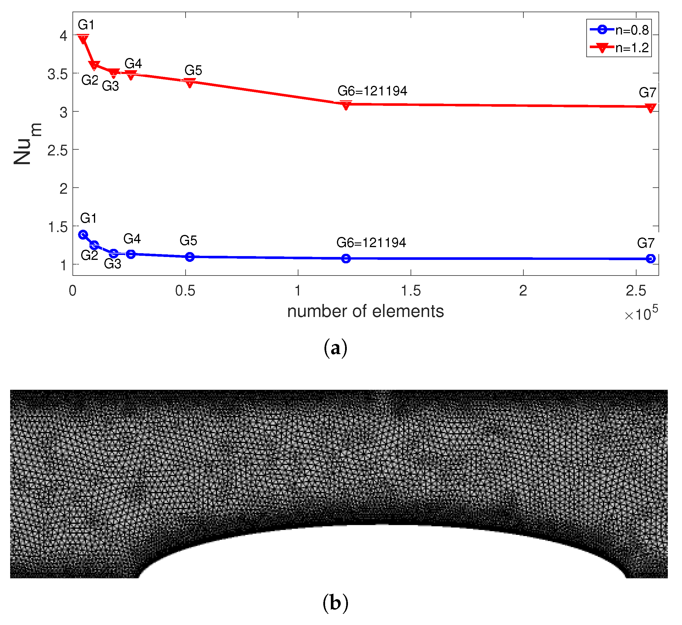
Mesh independence tests are performed to find the optimal mesh configuration. Test results with coarse grid (G1, 4551 number of elements) to extra fine grid (G7, 256,324 number of elements) are shown in Figure 2a at two power law indices. G6 (finer grid, 121,194 number of elements) is selected for the subsequent computations. Grid refinements were made near the walls and curved parts. Its distribution in the vicinity of the curved parts is given in Figure 2b.
Numerical code is validated by using results in different sources available in the literature. In the first work, local Nu number comparisons are made for the confined slot jet impingement HT under laminar flow conditions at several locations in Table 2 for Re = 100 as given in Ref. [53]. The overall agreement is satisfactory. In another work, comparisons of stagnation point Nu number are presented in Table 3 for confined slot jet impingement HT for different Re numbers available in the Refs. [54,55]. The highest deviation is found as 3.28% at Re = 100.
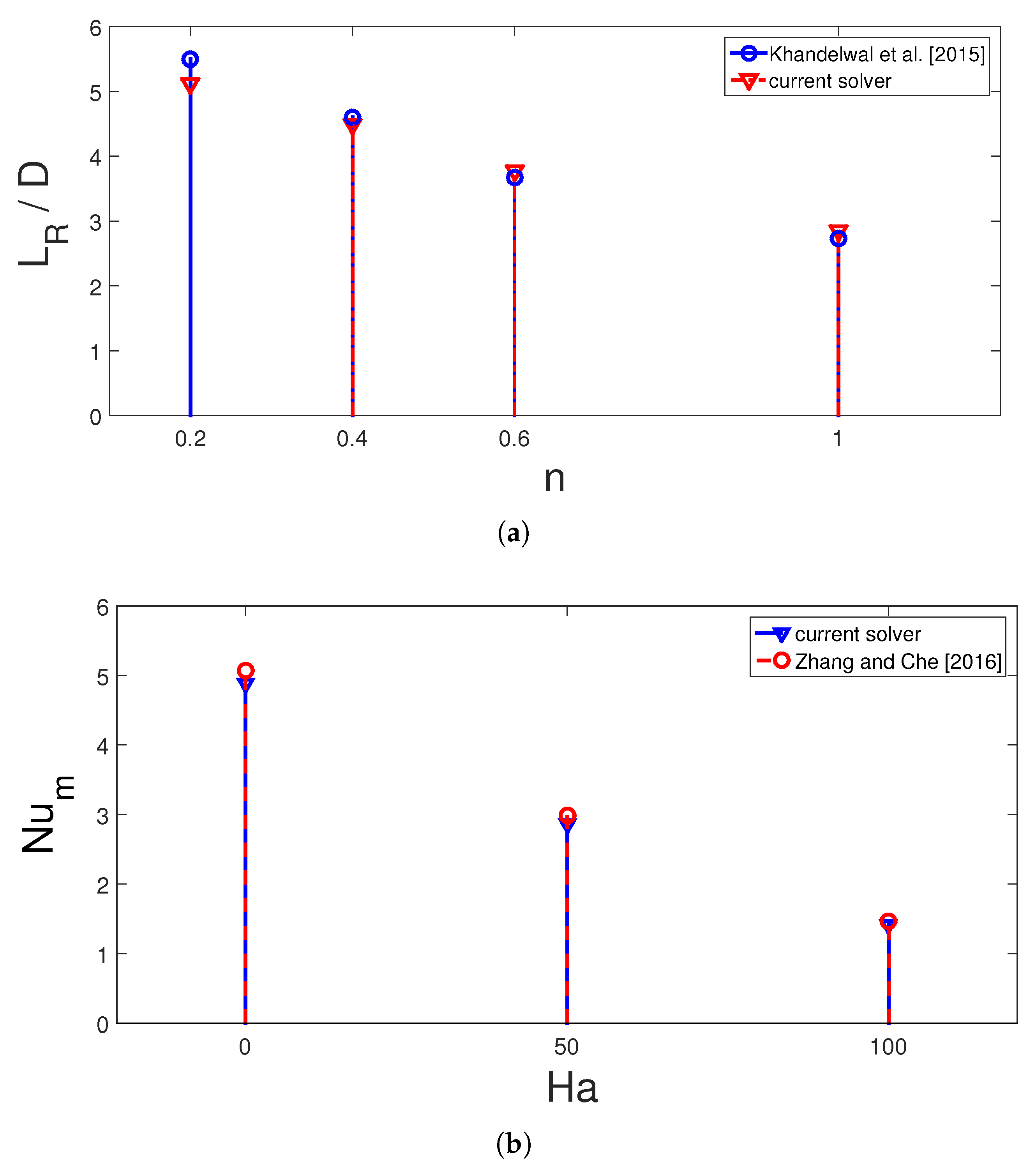
Impacts of using non-Newtonian power law fluids on the flow separation is considered for shear thinning fluid as in Ref. [56] for power law indices between 0.2 and 1. A correlation in the exponential form is proposed which depends upon the Re number and power law index. Comparison results of reattachment length with different power law indices at Re = 100 are given in Figure 3a,b. The highest difference of 5% is obtained with n = 0.2 . Validation study was also performed for case with MF effects. Convective HT with MF effects was considered and impacts of MF strength on average Nu comparisons are given in Figure 3b for fixed value of Grashof number at 2 × 10 5 . The highest deviation is found to be below 5% between the results of [57].

3. Results and Discussion

In this study, confined single and double jet impingement heat transfer for a non-Newtonian fluid under the effects of MF are analyzed. The MF is uniform throughout the domain while fluid type is power-law NF. Both SJ and DJ configurations are studied. The numerical analysis is performed for different values of Re number ( 100 Re 300 ), Hartmann number ( 0 Ha 10 ), inclination of MF ( 0 γ 90 ), aspect ratio of the curved surface ( 0.1 A R 1.20 ), power law index ( 0.8 n 1.2 ), nanoparticle volume fraction ( 0 ϕ 0.04 ) and particle size in nm ( 20 d p 80 ).
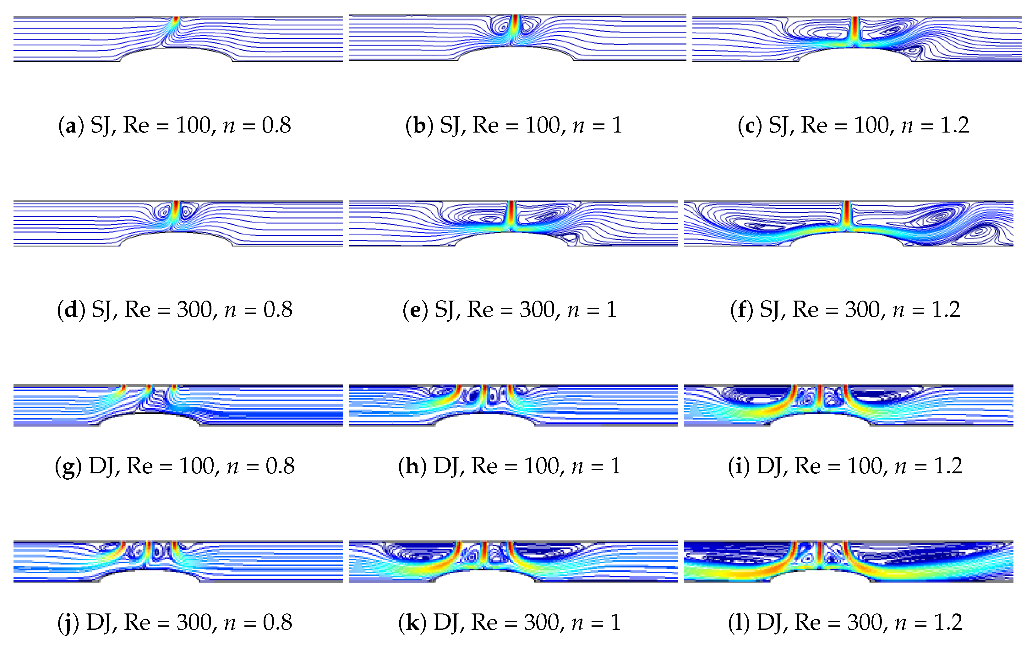
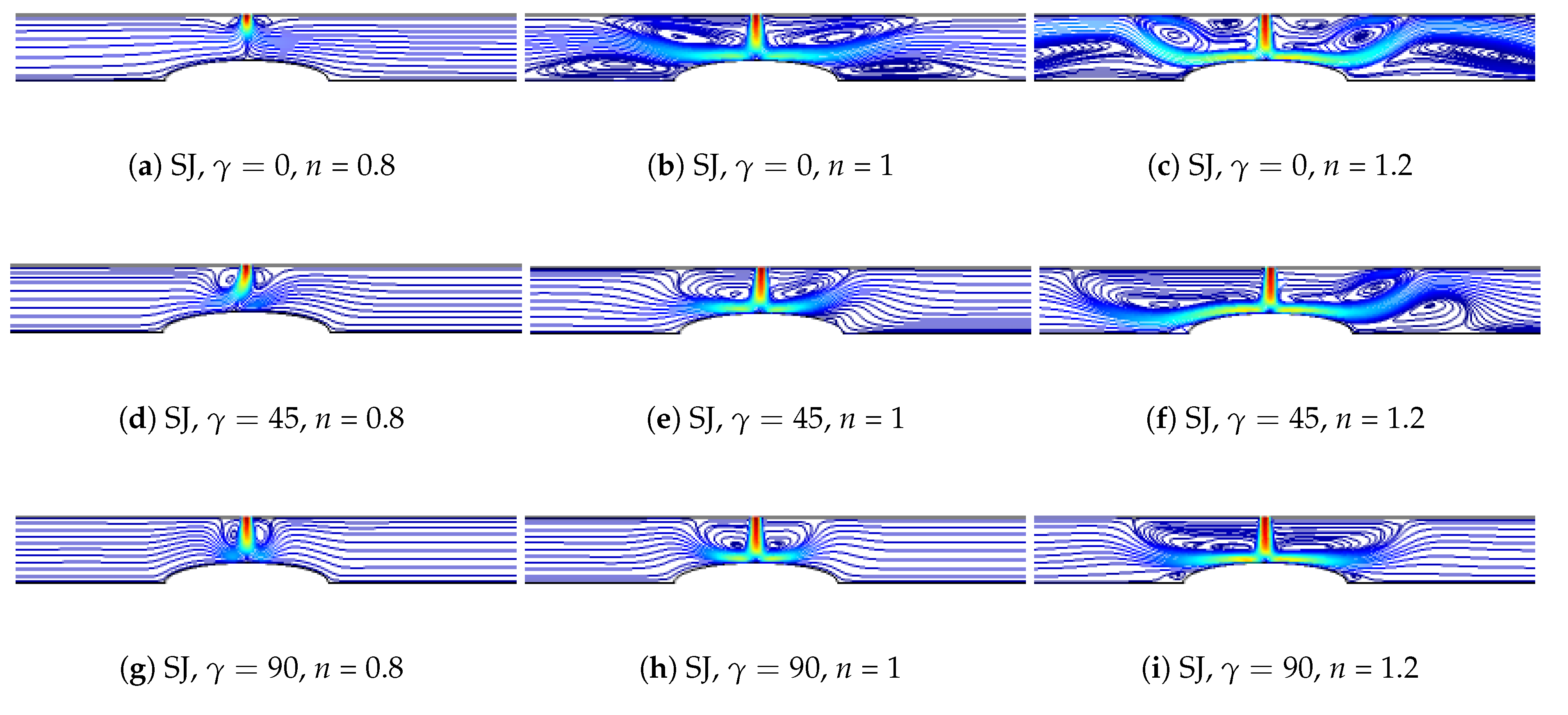
Impacts of Re number of the flow pattern (FP) variations are shown in Figure 4 (Ha = 5, γ = 45, A R = 0.25, ϕ = 0.04, d p 
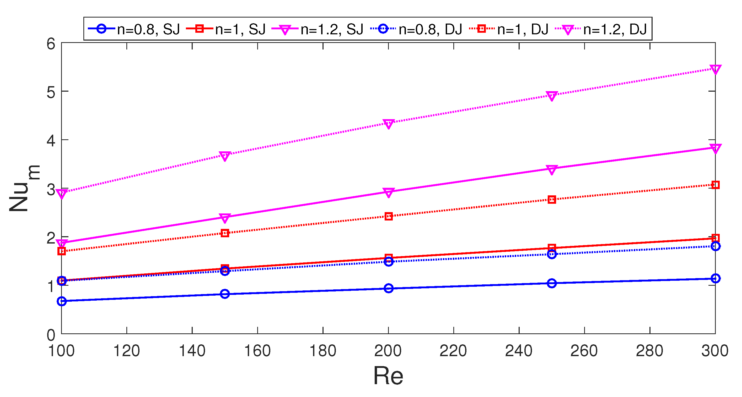
= 20 nm) for SJ and DJ configurations. At very low Re number for shear thinner fluid, due to presence of MF and its impact of the dampening of the fluid motion, no vortices are appeared. As the value of Re number is increased, flow recirculations are established near the inlet due to entertainment and confinement. For the shear thickening fluid, this vortex further increases in size due to the increased fluid velocity while at the wall jet region over the curved surface a recirculation zone is also established. Similar observations are seen for the the DJ configuration, but the occurrence of the vortices in between the jets is apparent. For shear thickening fluid at Re = 100 and Re = 300, the occurrence of secondary vortex on the bottom wall is distinguishable between the SJ and DJ configurations. Local Nu rises with higher power law index for both SJ and DJ cases while the secondary local peak in the Nu is also apparent for fluid with n = 1.2 at Re = 300 (Figure 5). In the case of DJ impingement, first three main peaks correspond to the impinging jet locations while other peaks denote the reattachment of the secondary vortex point on the bottom wall and size of those peaks increase with higher Re number. Average Nu number becomes higher for the DJ configurations as compared to SJ case. The discrepancies between the average Nu number of the DJ and SJ configurations become 61.9%, 54.9% and 55% for shear thinning fluid (n = 0.8), Newtonian fluid (n = 1) and shear thickening fluid (n = 01.2) at Re = 100 while these values become 58.7%, 56% and 42.8% at Re = 300. When Newtonian fluid (n = 1) is taken as reference fluid, discrepancies in average Nu between different fluid types become 38 % and 71.5% for n = 0.8 and n = 1.2 at Re = 100 with SJ configurations and these values become 42.2 % and 98% at Re = 300. In the SJ configuration, fluid with higher power law index resulted in higher variation in the average Nu as compared to Newtonian fluid and amount of increase depends upon the value of Re number. Similar observations are achieved for DJ case while amount of increment in the average Nu becomes 71% and 77.7% for n = 1.2 at Re = 100 and Re = 300 when compared to Newtonian fluid configuration (Figure 6).
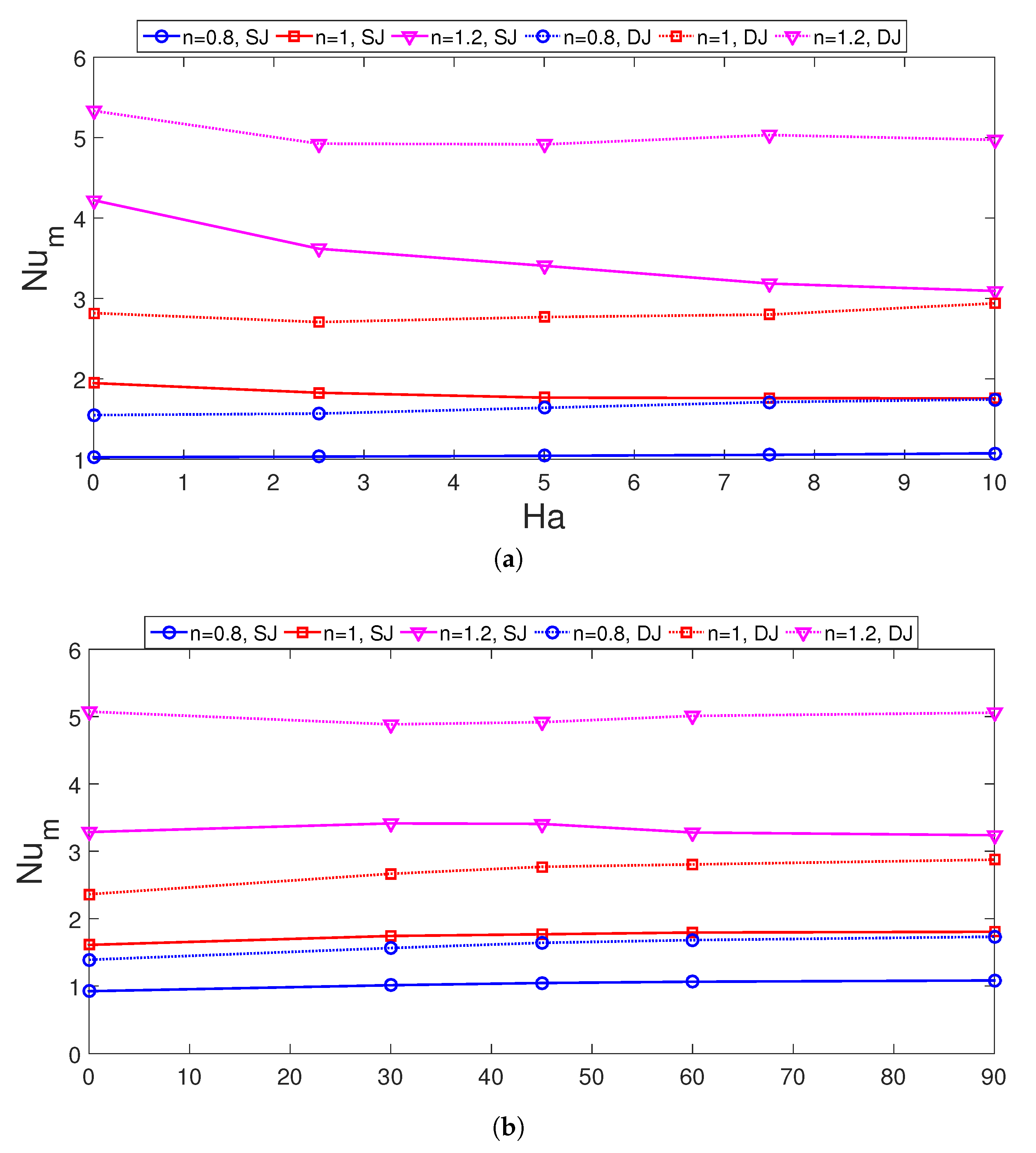
A uniform MF with inclination is imposed in the non-Newtonian fluid flow domain. The presence of the MF resulted in fluid flow motion dampening while the established recirculation zone size reduces as well. In the absence of MF with Newtonian fluid, vortices near the inlet and on the bottom wall occupies a large portion. As the power law index is increased to n = 1.2, near the inlet vortices form the multi-cellular flow structure while on the bottom wall the established recirculation zone size increases further. However, for shear thinning fluid (n = 0.8), the vortex size reduces in the inlet region while the bottom wall secondary vortices disappear due to the reduced fluid velocity in the absence of MF effects. For DJ configuration at the highest power law index, two vortices are formed in between the jets while the bottom vortex disappears and the number of vortex near the inlet jets becomes two. As the MF is imposed, the vortex sizes near the inlet jet and on the bottom wall reduces for both SJ and DJ configurations. The vortex size and numbers can be controlled with MF strength and power law index and for the case with highest MF strength, no vortices are formed for shear thinning fluid. The MF inclination also plays an important role in controlling the vortex size as shown in Figure 7 at Ha = 5. The inlet vortex size diminishes with higher MF inclination angles for Newtonian and shear thinning fluid while the impact is reverse for shear thinning fluid where small vortcies are established near the inlet jet for this fluid type. The suppression of the bottom vortcies with higher values of γ is apparent for power law index of n = 1 and n = 1.2 (
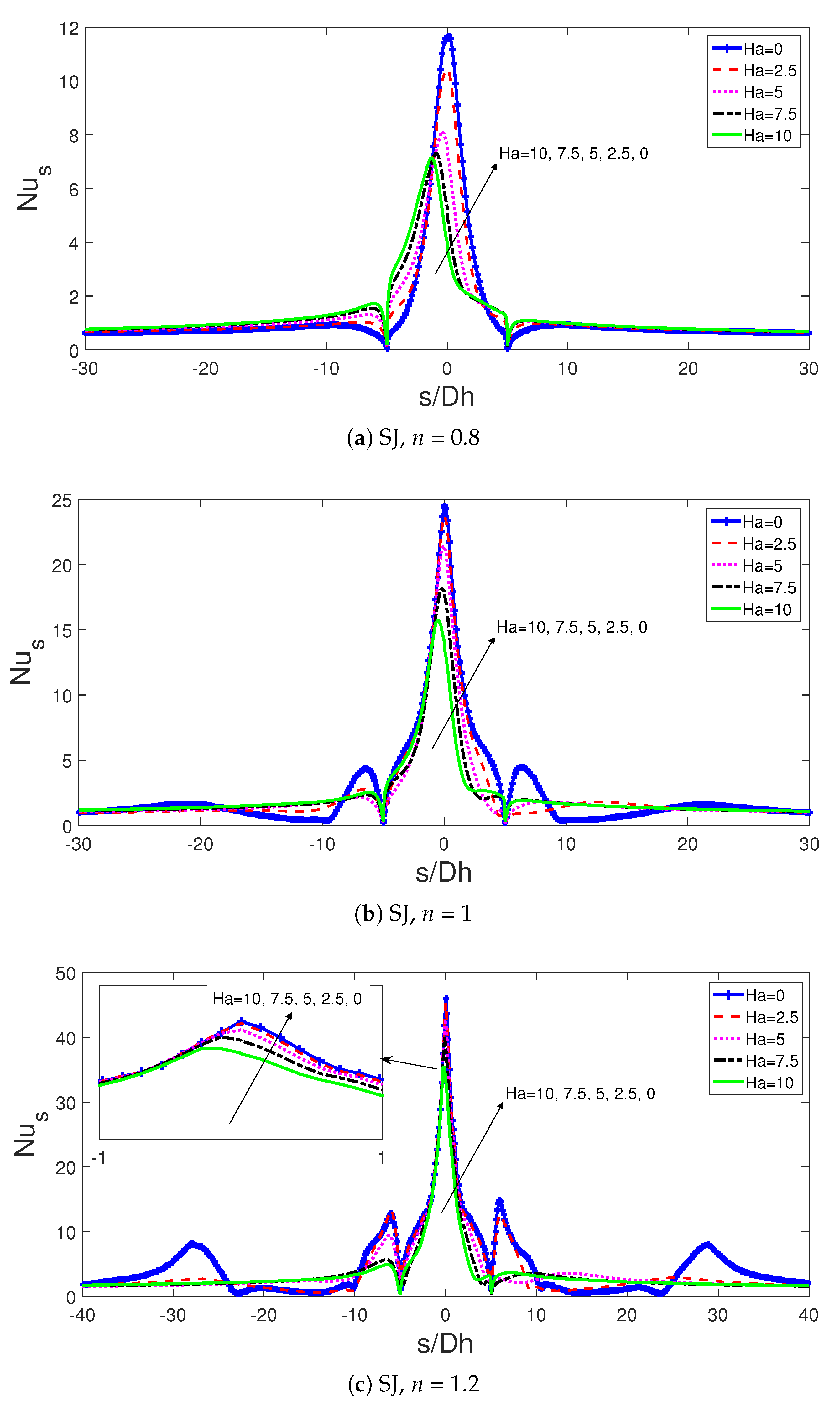
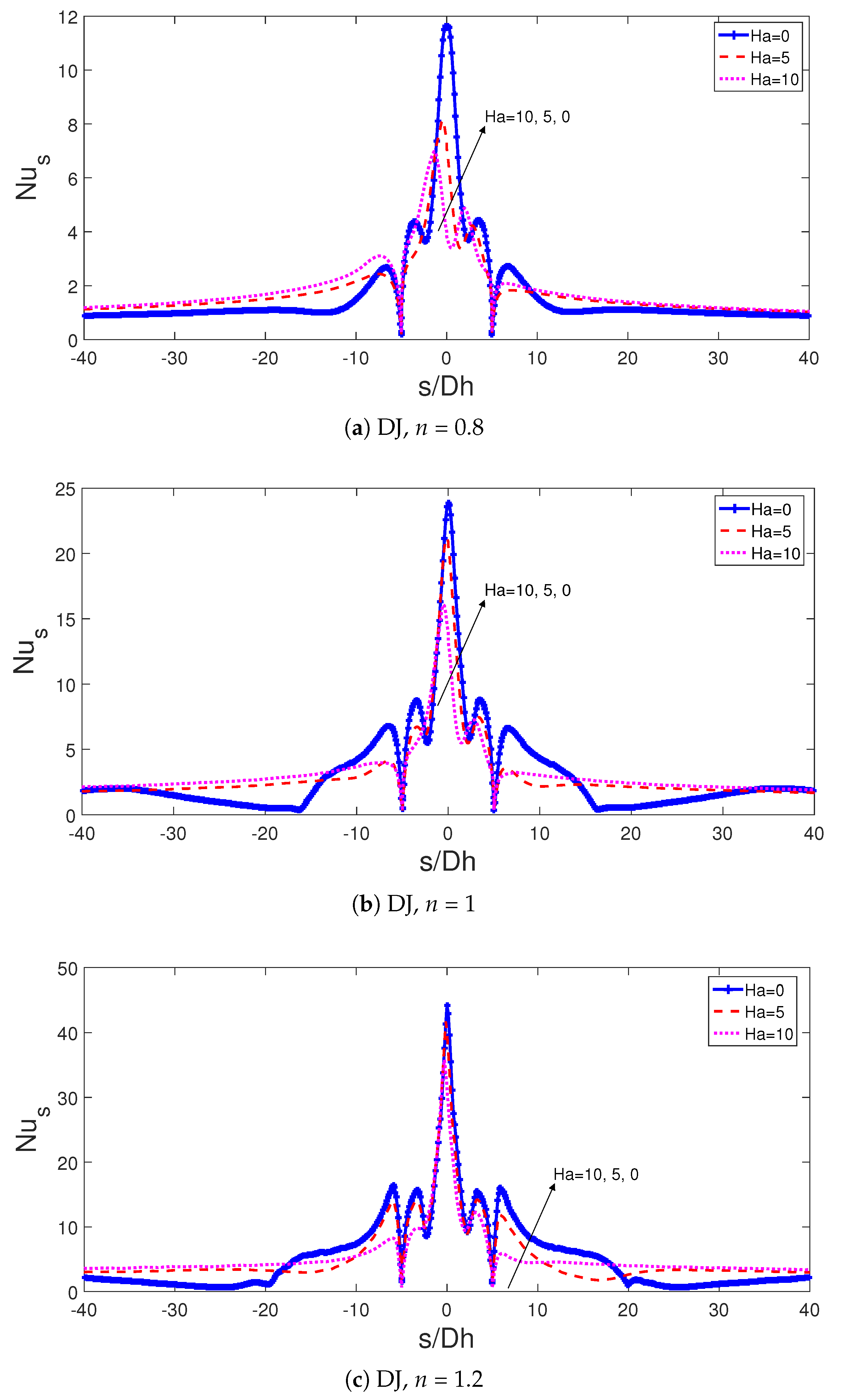
Figure 8). Impacts of MF strength on the local Nu number distribution for three different power law index are given in Figure 9 for SJ and in Figure 10 for DJ configurations. Local peak of Nu is reduced with higher MF strength and additional local peaks are observed as the power law index is increased. These peaks are also damped with higher values of Ha number. There is also a shift in the local peak of Nu number with higher MF strength especially for the shear thinning fluid. Similar observations are obtained for the local peaks of the Nu number with varying MF strength. The impact of MF on the average Nu variation depends on the fluid type. When MF is imposed at the highest strength as compared to non-MF case, there is 26.6% and 7.5% reduction in the average Nu number for shear thickening fluid with SJ and DJ configurations while the average Nu rises by about 4.78% and 12.58 % for shear thinning fluid where the heat transfer rate is low. As Newtonian fluid is considered, there is reduction of 10.48% in the average Nu with highest MF strength for SJ case while it is increased by about 4.6% for DJ case. The suppression of the secondary peaks due top the bottom vortex and reduction of the impinging point Nu number with MF strength in DJ case determined the amount of enhancement or reduction in the average Nu number for power law indices n = 1 and n = 1.2. The highest value of average Nu with varying MF inclination is achieved at different γ depending upon the fluid type and jet configuration.
When shear thickening fluid (n = 1.2) is considered, the highest Nu is obtained at γ = 30 for SJ case while it is minimum for DJ case. For SJ configuration, there is 7.3%, 11.8% and 1.5% variations in the average Nu number with fluids at power law index of n = 0.8, n = 1 and n = 1.2 when horizontal and vertical alignment of MF are compared while these values become 24.6%, 20.7% and 0.5% for DJ configuration (Figure 11).
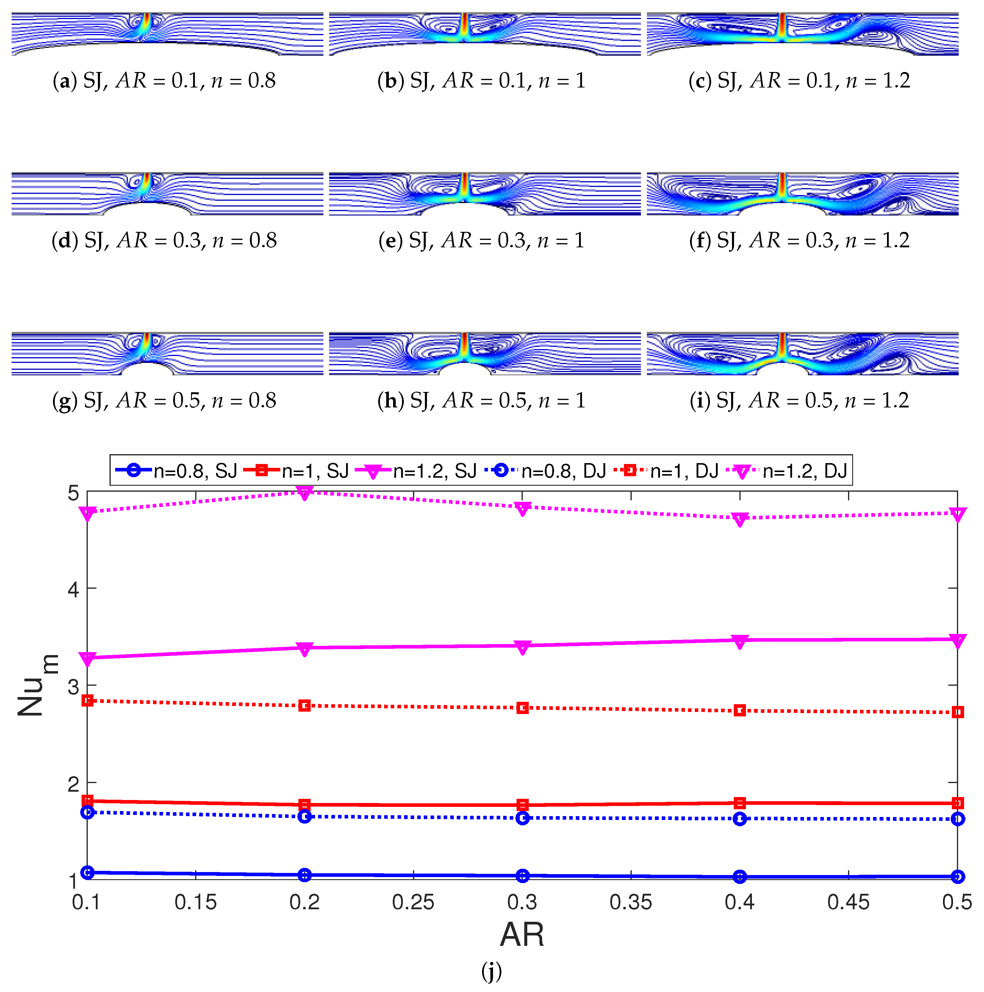
The partly curved wall size impacts on FPs for SJ case and average Nu variations for SJ and DJ cases are shown in Figure 12a–i and in Figure 12j. The curvature is an ellipse while the effects are characterized by aspect ratio (AR) which denotes the ratio of the radius in the minor and major axis. For the fixed value of minor axis radius, increasing the AR reduces the size of the ellipse in the wall jet direction. The fluid impinges on the curved surface and a separated flow region is established in the wall jet region over the curved surface for shear thickening fluid at A R = 0.1 while it occurs away from the curve surface near the flat bottom wall for A R = 0.5. For shear thinning fluid, recirculations on the partly curved wall are not appeared for all values of A R . The recirculation near the inlet are affected by varying the A R values especially for power law index of n = 1.2 which is due to the occurrence of the secondary recirculation zones. Average Nu variation is 5.8% for n = 1.2 with SJ configuration and it is 5.43% for n = 0.8 with DJ case when lowest and highest A R values are considered.
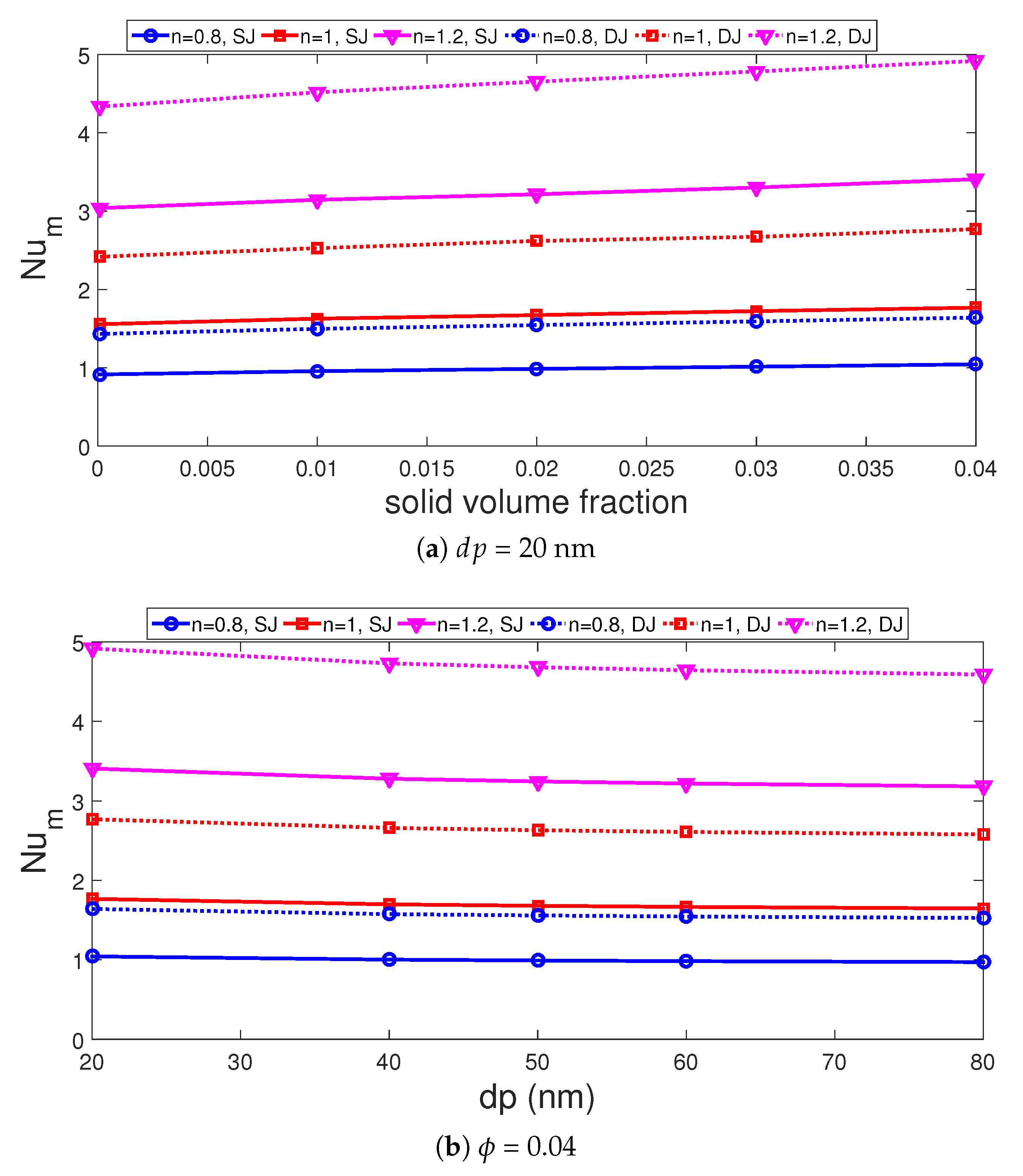
Adding nano-sized particles and varying its size changed the convective heat transfer features for fluids with different power law indices as shown in Figure 13a,b. The increment amount with ϕ depends upon the jet configuration and fluid type. Configurations with DJ and shear thinning fluid (n = 0.8) resulted in the highest HT increment which is 14.7% as compared to pure water at the same power law index while this value is 14.10% for SJ configuration. However, for shear thickening fluid, the potentiality of using NFs in HT enhancement becomes lower which is 12% for SJ and 13.4% for DJ cases. It is advantageous to use NFs in DJ configurations but the difference in HT enhancement with NF is below 2% when compared to SJ case at the same ϕ . Higher nanoparticle size resulted in lower values of average Nu and the amount of decrement is between 6% and 7% for SJ and DJ configurations with various power law indices.

ANFIS (Adaptive Neuro-Fuzzy Interface System) Based Modeling

Convective HT performance is predicted by using ANFIS based modeling approach for SJ configurations. Soft computing methods are frequently used in thermal engineering systems and renewable energy systems. There are diverse methods and ANFIS is a powerful technique that uses the artificial neural networks (ANN) with fuzzy logic [58,59]. In the ANFIS modeling approach, fuzzy interface system has rule base with membership functions and has a reasoning mechanism which performs inference operation to get the model output. Let us consider x 1 , x 2 as the input and y as output of a a fuzzy inference system while the rule base contains two fuzzy if-then Takagi and Sugeno’s type rules [58,60]:
Rule 1 : If ( x 1 i s A 1 ) a n d ( x 2 i s B 1 ) then f 1 = p 1 x 1 + q 1 x 2 + r 1 Rule 2 : If ( x 1 i s A 2 ) a n d ( x 2 i s B 2 ) then f 2 = p 2 x 1 + q 2 x 2 + r 2 .
In the above representation, fuzzy sets are denoted by A i and B i while f i denotes the output within the fuzzy region. The parameters p i , q i and r i are obtained from training phase.
Different layers are available in the ANFIS modeling [61]. Input variable is blurred with the membership functions in the fuzification layer while the membership grade for the input variable is formed. In the second layer, fixed nodes and the product is the firing strength of the rule as denoted by:
w i = μ A i ( x 1 ) μ B i ( x 2 )
The normalized firing strength is got in the third layer as:
w ¯ i = w i w 1 + w 2 .
The outputs of each node is got with multiplying the normalizing firing strength and first order order polynomial rule as in the defuzzifying layer as:
w ¯ i f i = p i x + q i y + r i .
In the last layer, the overall output is got while the parameters of first and fourth layer are adjusted in the training phase with a learning algorithm. A learning algorithm which is a hybrid type is used.
The model quality can be measured by using mean square error (MSE), mean absolute error (MAE) and coefficient of determination ( R 2 ). The MSE and R 2 are defined as in the following:
MSE = 1 M i = 1 M y i C F D y i 2 .
while the coefficient of determination ( R 2 ) is stated as in the following:
R 2 = 1 i = 1 M y i C F D y 2 i = 1 M y i C F D y ¯ 2
with M representing the simulation data set number while y ¯ denotes the average value.
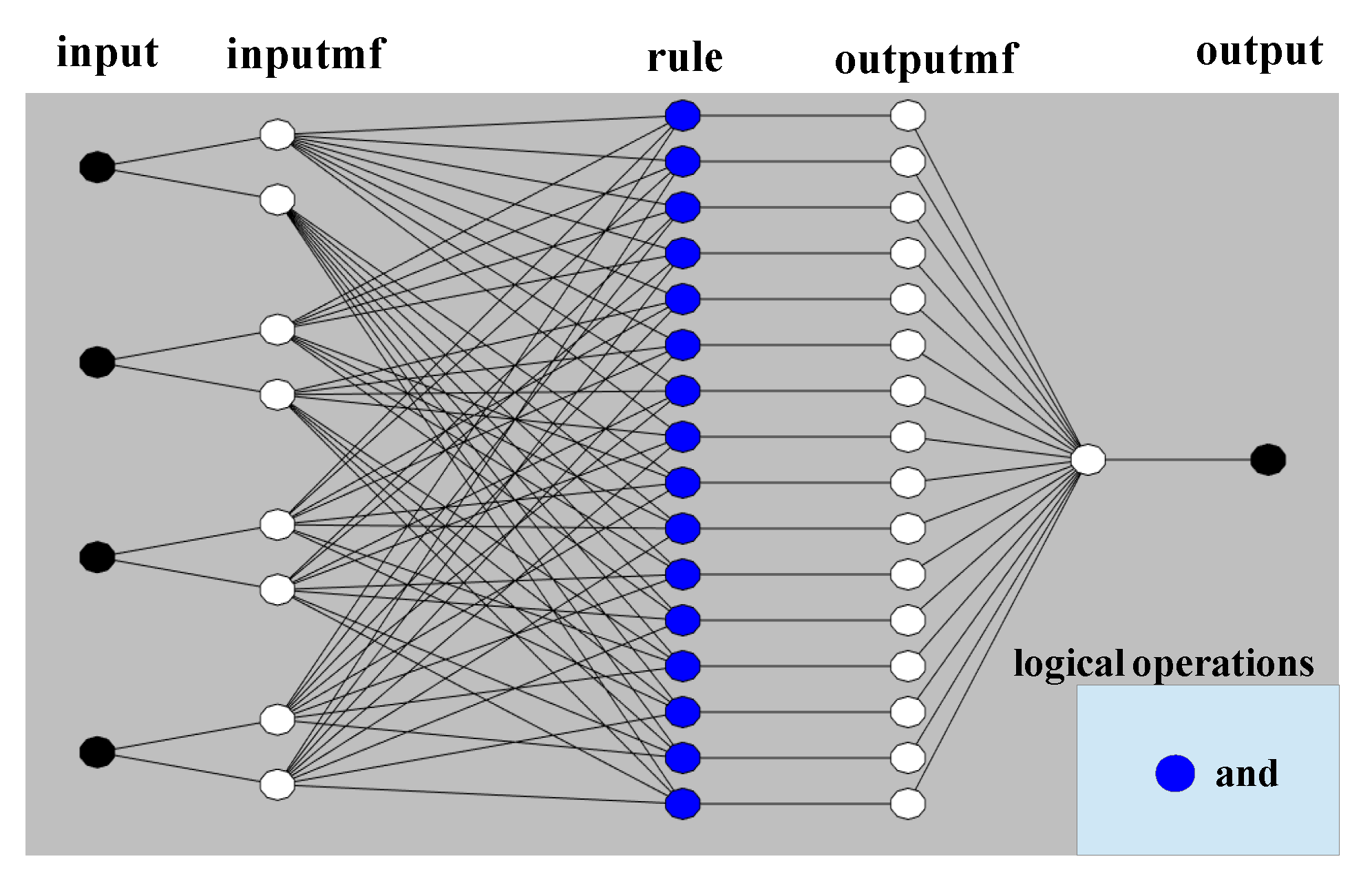
In the modeling with ANFIS, four inputs and one output are used by using the parametric data from CFD computations for SJ configuration. The input variables are the Reynolds number (Re, 100 Re 300 ), Hartmann number (Ha, 0 Ha 10 ), power law index (n, 0.8 n 1.2 ) and aspect ratio of the curved wall (AR, 0.1 A R 1.20 ). Five different values for each of the input parameters are considered with ϕ = 0.04 and d p = 20 nm. In total, 625 numerical simulation data are used and number of training and testing data set to ANFIS are 438 and 187 (Random data division is used). ANFIS model structure with 4 inputs and 1 outputs are shown in Figure 14. ANFIS model parameters are given in Table 4. Model performances for training and testing are given in Table 5 with low values of MSE and R 2 values are closer to 1. 
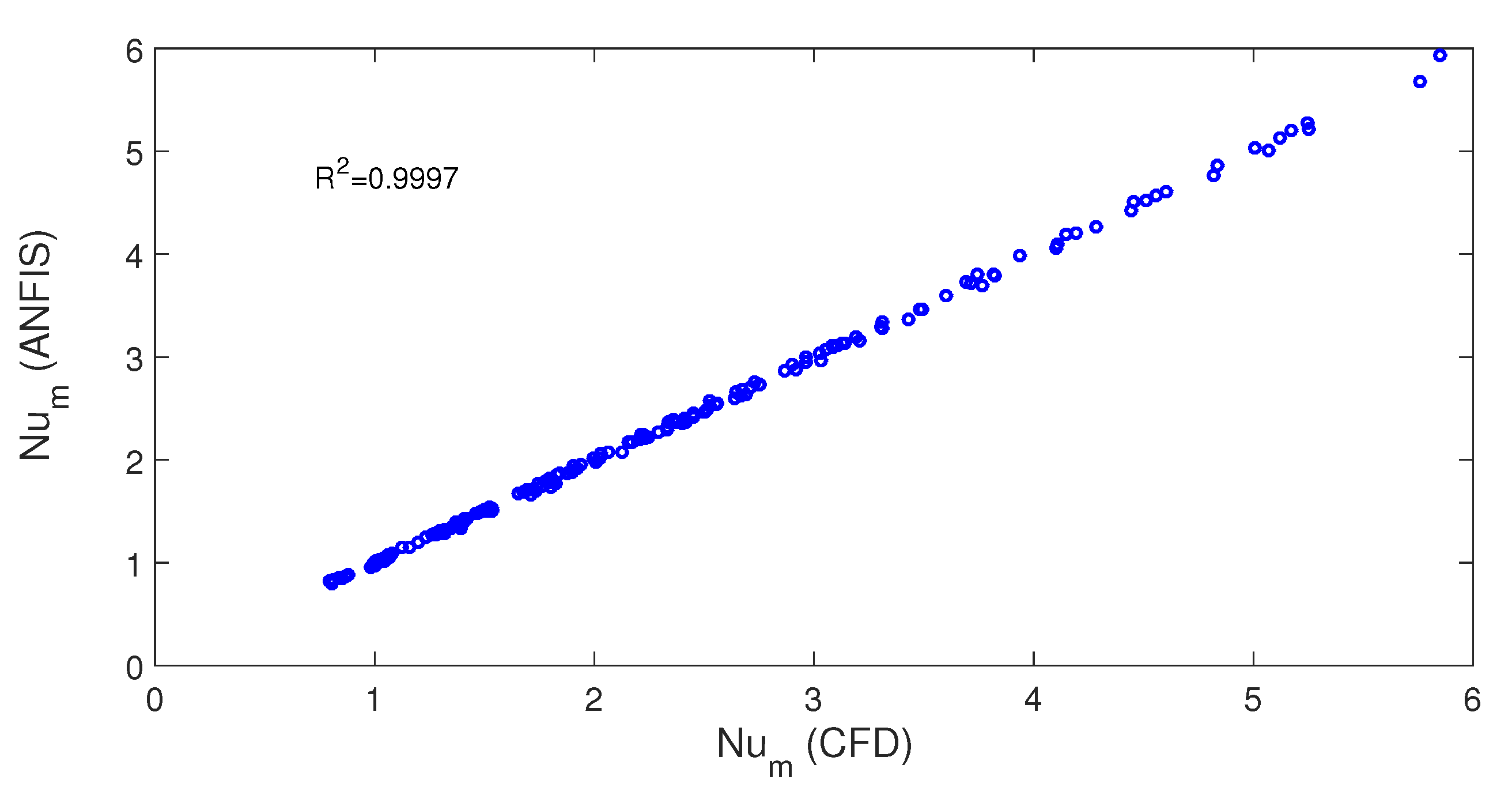
Figure 15 shows the average Nu comparisons between the ANFIS and CFD for validation. The generated surface plots with ANFIS for variation of average Nu with respect to changes in various inputs, input 1-Re number, input 2- Ha number, input 3- power law index, input 4- aspect ratio) are shown in Figure 16. Higher accuracy and predictions for convective HT performance are achieved with ANFIS based modeling.

4. Conclusions

Convective HT with impinging jets of non-Newtonian power law fluid of NF is analyzed under the impacts of MF for a partly curved surface. Both single and double-jet configurations are considered. For both SJ and DJ cases, higher deviations in the average Nu is attained when compared to Newtonian NF as the power law index becomes higher while the amount of rise in the HT depends upon the Re number. The discrepancy in the average Nu becomes 38 % and 71.5% for power law indices of 0.8 and 1.2 when compared to Newtonian fluid at Re number of 100 for SJ case while they are obtained as 42.2% and 98% for Re number of 300. The recirculation zones near the inlet and on the bottom wall are affected by the MF strength and it inclinations. The size of the vortices and their numbers can be controlled strength of MF and power law index. When the MF is imposed at the highest strength as compared to non-MF configuration, the average Nu is reduced by about 26.6% and 7.5% with shear thickening fluid for SJ and DJ cases. However with shear thinning fluid, it raises by about 4.78% and 12.58%. The MF inclination impact on the variation of average Nu is 24.6%, 20.7% and 0.5% for DJ case when MF is imposed horizontally and vertically for power law indices of 0.8, 1 and 1.2. The aspect ratio of the elliptical curvature of the target surface has slightly affected the FP variations while average HT variation is below 6%. The average Nu increment is in the range of 12% and 14% with nanoparticles inclusion in the base fluid for different power law indices. However, the decrements in the average Nu with higher particle sizes is between 6% and 7% for SJ and DJ configurations. The outcomes of this study will be helpful for the initial design and optimization of thermal systems in different application areas such as in solar energy (cooling of a PV panel), in some chemical processes, turbo machinery and many others. The MF effects may be considered in J-I such as for molten metals or it can be used with nanofluids as convective HT control. The curvature effects of the surface with impinging jets are also considered. The present study may be extended to include different thermal boundary conditions, flow pulsation effects, different forms of the curvature, shape effects of the nanoparticles, non uniform MF effects and different non-Newtonian fluid types which will increase the applicability of the present results.

Author Contributions

Conceptualization, F.S.; methodology, F.S., H.F.O. and A.J.C.; software, F.S.; validation, H.F.O.; formal analysis, F.S.; investigation, F.S., H.F.O., A.J.C.; writing—original draft preparation, F.S.; writing—review and editing, F.S., H.F.O. and A.J.C.; visualization, F.S., H.F.O. and A.J.C.; supervision, F.S., H.F.O. and A.J.C. All authors have read and agreed to the published version of the manuscript.

Funding

This research received no external funding.

Institutional Review Board Statement

Not applicable.

Informed Consent Statement

Not applicable.

Data Availability Statement

Not applicable.

Conflicts of Interest

The authors declare no conflict of interest.

Abbreviations

a, bradii of the elliptic curvature
ARaspect ratio
dpparticle diameter
hlocal heat transfer coefficient
kthermal conductivity
Hdistance between the plates
HaHartmann number
npower law index
Nu x local Nusselt number
Nu m average Nusselt number
ppressure
PrPrandtl number
ReReynolds number
Ttemperature
u, vx-y velocity components
x, yCartesian coordinates
Greek Characters
α thermal diffusivity
ϕ solid volume fraction
ν kinematic viscosity
θ non-dimensional temperature
ρ density of the fluid
γ inclination angle
τ shear stress
Subscripts
ccold
hhot
maverage
nfnanofluid
psolid particle

References

  1. Maghrabie, H.M. Heat transfer intensification of jet impingement using exciting jets-A comprehensive review. Renew. Sustain. Energy Rev. 2021, 139, 110684. [Google Scholar] [CrossRef]
  2. Garimella, S.V. Heat transfer and flow fields in confined jet impingement. Annu. Rev. Heat Transf. 2000, 11, 413–494. [Google Scholar] [CrossRef]
  3. Bahaidarah, H.M. Experimental performance evaluation and modeling of jet impingement cooling for thermal management of photovoltaics. Sol. Energy 2016, 135, 605–617. [Google Scholar] [CrossRef]
  4. Javidan, M.; Moghadam, A.J. Experimental investigation on thermal management of a photovoltaic module using water-jet impingement cooling. Energy Convers. Manag. 2021, 228, 113686. [Google Scholar] [CrossRef]
  5. Hasan, H.A.; Sopian, K.; Jaaz, A.H.; Al-Shamani, A.N. Experimental investigation of jet array nanofluids impingement in photovoltaic/thermal collector. Sol. Energy 2017, 144, 321–334. [Google Scholar] [CrossRef]
  6. Nadda, R.; Kumar, A.; Maithani, R. Efficiency improvement of solar photovoltaic/solar air collectors by using impingement jets: A review. Renew. Sustain. Energy Rev. 2018, 93, 331–353. [Google Scholar] [CrossRef]
  7. Zhong, X.; Zhang, Y.; Hou, Y.; Feng, H.; Sun, L. Unique dynamics of water-ethanol binary droplets impacting onto a superheated surface with nanotubes. Int. J. Heat Mass Transf. 2021, 164, 120571. [Google Scholar] [CrossRef]
  8. Izadi, S.; Armaghani, T.; Ghasemiasl, R.; Chamkha, A.J.; Molana, M. A comprehensive review on mixed convection of nanofluids in various shapes of enclosures. Powder Technol. 2019, 343, 880–907. [Google Scholar] [CrossRef]
  9. Oztop, H.F.; Abu-Nada, E. Numerical study of natural convection in partially heated rectangular enclosures filled with nanofluids. Int. J. Heat Fluid Flow 2008, 29, 1326–1336. [Google Scholar] [CrossRef]
  10. Arshad, W.; Ali, H.M. Graphene nanoplatelets nanofluids thermal and hydrodynamic performance on integral fin heat sink. Int. J. Heat Mass Transf. 2017, 107, 995–1001. [Google Scholar] [CrossRef]
  11. Yang, L.; Jiang, W.; Ji, W.; Mahian, O.; Bazri, S.; Sadri, R.; Badruddin, I.A.; Wongwises, S. A review of heating/cooling processes using nanomaterials suspended in refrigerants and lubricants. Int. J. Heat Mass Transf. 2020, 153, 119611. [Google Scholar] [CrossRef]
  12. Abbas, F.; Ali, H.M.; Shah, T.R.; Babar, H.; Janjua, M.M.; Sajjad, U.; Amer, M. Nanofluid: Potential evaluation in automotive radiator. J. Mol. Liq. 2020, 297, 112014. [Google Scholar] [CrossRef]
  13. Singh, T.; Atieh, M.A.; Al-Ansari, T.; Mohammad, A.W.; McKay, G. The role of nanofluids and renewable energy in the development of sustainable desalination systems: A review. Water 2020, 12, 2002. [Google Scholar] [CrossRef]
  14. Selimefendigil, F.; Öztop, H.F. Performance assessment of a thermoelectric module by using rotating circular cylinders and nanofluids in the channel flow for renewable energy applications. J. Clean. Prod. 2021, 279, 123426. [Google Scholar] [CrossRef]
  15. Shamshirgaran, S.R.; Al-Kayiem, H.H.; Sharma, K.V.; Ghasemi, M. State of the Art of Techno-Economics of Nanofluid-Laden Flat-Plate Solar Collectors for Sustainable Accomplishment. Sustainability 2020, 12, 9119. [Google Scholar] [CrossRef]
  16. Mahian, O.; Kolsi, L.; Amani, M.; Estellé, P.; Ahmadi, G.; Kleinstreuer, C.; Marshall, J.S.; Siavashi, M.; Taylor, R.A.; Niazmand, H.; et al. Recent advances in modeling and simulation of nanofluid flows-Part I: Fundamentals and theory. Phys. Rep. 2019, 790, 1–48. [Google Scholar] [CrossRef]
  17. Chamkha, A.J.; Molana, M.; Rahnama, A.; Ghadami, F. On the nanofluids applications in microchannels: A comprehensive review. Powder Technol. 2018, 332, 287–322. [Google Scholar] [CrossRef]
  18. Shahsavar, A. Experimental evaluation of energy and exergy performance of a nanofluid-based photovoltaic/thermal system equipped with a sheet-and-sinusoidal serpentine tube collector. J. Clean. Prod. 2020, 287, 125064. [Google Scholar] [CrossRef]
  19. Bozorg, M.V.; Siavashi, M. Two-phase mixed convection heat transfer and entropy generation analysis of a non-Newtonian nanofluid inside a cavity with internal rotating heater and cooler. Int. J. Mech. Sci. 2019, 151, 842–857. [Google Scholar] [CrossRef]
  20. Selimefendigil, F.; Öztop, H.F. Identification of pulsating flow effects with CNT nanoparticles on the performance enhancements of thermoelectric generator (TEG) module in renewable energy applications. Renew. Energy 2020, 162, 1076–1086. [Google Scholar] [CrossRef]
  21. Manca, O.; Mesolella, P.; Nardini, S.; Ricci, D. Numerical study of a confined slot impinging jet with nanofluids. Nanoscale Res. Lett. 2011, 6, 188. [Google Scholar] [CrossRef] [PubMed] [Green Version]
  22. Zahmatkesh, I.; Ali Naghedifar, S. Oscillatory mixed convection in the jet impingement cooling of a horizontal surface immersed in a nanofluid-saturated porous medium. Numer. Heat Transf. Part A Appl. 2017, 72, 401–416. [Google Scholar] [CrossRef]
  23. Mahdavi, M.; Sharifpur, M.; Meyer, J.P. Fluid flow and heat transfer analysis of nanofluid jet cooling on a hot surface with various roughness. Int. Commun. Heat Mass Transf. 2020, 118, 104842. [Google Scholar] [CrossRef]
  24. Selimefendigil, F.; Öztop, H.F. Analysis and predictive modeling of nanofluid-jet impingement cooling of an isothermal surface under the influence of a rotating cylinder. Int. J. Heat Mass Transf. 2018, 121, 233–245. [Google Scholar] [CrossRef]
  25. Li, Q.; Xuan, Y.; Yu, F. Experimental investigation of submerged single jet impingement using Cu–water nanofluid. Appl. Therm. Eng. 2012, 36, 426–433. [Google Scholar] [CrossRef]
  26. Lv, J.; Hu, C.; Bai, M.; Zeng, K.; Chang, S.; Gao, D. Experimental investigation of free single jet impingement using SiO2-water nanofluid. Exp. Therm. Fluid Sci. 2017, 84, 39–46. [Google Scholar] [CrossRef]
  27. Mohammadpour, J.; Lee, A. Investigation of nanoparticle effects on jet impingement heat transfer: A review. J. Mol. Liq. 2020, 316, 113819. [Google Scholar] [CrossRef]
  28. Ellahi, R.; Aziz, S.; Zeeshan, A. Non-Newtonian nanofluid flow through a porous medium between two coaxial cylinders with heat transfer and variable viscosity. J. Porous Media 2013, 16, 205–216. [Google Scholar] [CrossRef]
  29. Domairry, D.; Sheikholeslami, M.; Ashorynejad, H.R.; Gorla, R.S.R.; Khani, M. Natural convection flow of a non-Newtonian nanofluid between two vertical flat plates. Proc. Inst. Mech. Eng. Part N J. Nanoeng. Nanosyst. 2011, 225, 115–122. [Google Scholar] [CrossRef]
  30. Khan, Z.; Khan, Z.; Ghafoor, A. A review of performance enhancement of PCM based latent heat storage system within the context of materials, thermal stability and compatibility. Energy Convers. Manag. 2016, 115, 132–158. [Google Scholar] [CrossRef]
  31. Kefayati, G. Simulation of double diffusive MHD (magnetohydrodynamic) natural convection and entropy generation in an open cavity filled with power-law fluids in the presence of Soret and Dufour effects (part II: Entropy generation). Energy 2016, 107, 917–959. [Google Scholar] [CrossRef]
  32. Alsabery, A.; Chamkha, A.; Saleh, H.; Hashim, I. Transient natural convective heat transfer in a trapezoidal cavity filled with non-Newtonian nanofluid with sinusoidal boundary conditions on both sidewalls. Powder Technol. 2017, 308, 214–234. [Google Scholar] [CrossRef]
  33. Kefayati, G.R. Simulation of heat transfer and entropy generation of MHD natural convection of non-Newtonian nanofluid in an enclosure. Int. J. Heat Mass Transf. 2016, 92, 1066–1089. [Google Scholar] [CrossRef]
  34. Gharraei, R.; Vejdani, A.; Baheri, S.; Davani, A.A. Numerical investigation on the fluid flow and heat transfer of non-Newtonian multiple impinging jets. Int. J. Therm. Sci. 2016, 104, 257–265. [Google Scholar] [CrossRef]
  35. Gorla, R.S.R. Laminar swirling power law non-newtonian fluid jet impinging on a normal plane. J. Non-Newton. Fluid Mech. 1977, 2, 299–306. [Google Scholar] [CrossRef]
  36. Chatterjee, A.; Dhingra, S.; Kapur, S.S. Laminar impinging jet heat transfer with a purely viscous inelastic fluid. Numer. Heat Transf. Part A Appl. 2002, 42, 193–213. [Google Scholar] [CrossRef]
  37. Lamraoui, H.; Mansouri, K.; Saci, R. Numerical investigation on fluid dynamic and thermal behavior of a non-Newtonian Al2O3-water nanofluid flow in a confined impinging slot jet. J. Non-Newton. Fluid Mech. 2019, 265, 11–27. [Google Scholar] [CrossRef]
  38. Nakharintr, L.; Naphon, P. Magnetic field effect on the enhancement of nanofluids heat transfer of a confined jet impingement in mini-channel heat sink. Int. J. Heat Mass Transf. 2017, 110, 753–759. [Google Scholar] [CrossRef]
  39. Lee, H.; Ha, M.; Yoon, H. A numerical study on the fluid flow and heat transfer in the confined jet flow in the presence of magnetic field. Int. J. Heat Mass Transf. 2005, 48, 5297–5309. [Google Scholar] [CrossRef]
  40. Ha, M.Y.; Lee, H.G.; Seong, S.H. Numerical simulation of three-dimensional flow, heat transfer, and solidification of steel in continuous casting mold with electromagnetic brake. J. Mater. Process. Technol. 2003, 133, 322–339. [Google Scholar] [CrossRef]
  41. Izadi, A.; Siavashi, M.; Rasam, H.; Xiong, Q. MHD enhanced nanofluid mediated heat transfer in porous metal for CPU cooling. Appl. Therm. Eng. 2020, 168, 114843. [Google Scholar] [CrossRef]
  42. Selimefendigil, F.; Öztop, H.F. Al2O3-water nanofluid jet impingement cooling with magnetic field. Heat Transf. Eng. 2020, 41, 50–64. [Google Scholar] [CrossRef]
  43. Nimmagadda, R.; Haustein, H.D.; Asirvatham, L.G.; Wongwises, S. Effect of uniform/non-uniform magnetic field and jet impingement on the hydrodynamic and heat transfer performance of nanofluids. J. Magn. Magn. Mater. 2019, 479, 268–281. [Google Scholar] [CrossRef]
  44. Selimefendigil, F.; Öztop, H.F. MHD Pulsating forced convection of nanofluid over parallel plates with blocks in a channel. Int. J. Mech. Sci. 2019, 157, 726–740. [Google Scholar] [CrossRef]
  45. Selimefendigil, F.; Öztop, H.F. Cooling of a partially elastic isothermal surface by nanofluids jet impingement. J. Heat Transf. 2018, 140, 042205. [Google Scholar] [CrossRef]
  46. Cornaro, C.; Fleischer, A.S.; Rounds, M.; Goldstein, R.J. Jet impingement cooling of a convex semi-cylindrical surface. Int. J. Therm. Sci. 2001, 40, 890–898. [Google Scholar] [CrossRef]
  47. Gau, C.; Chung, C. Surface curvature effect on slot-air-jet impingement cooling flow and heat transfer process. J. Heat Transf. 1991, 113, 858–864. [Google Scholar] [CrossRef]
  48. Selimefendigil, F.; Öztop, H.F. Jet impingement cooling and optimization study for a partly curved isothermal surface with CuO-water nanofluid. Int. Commun. Heat Mass Transf. 2017, 89, 211–218. [Google Scholar] [CrossRef]
  49. Sharif, M.; Mothe, K. Evaluation of turbulence models in the prediction of heat transfer due to slot jet impingement on plane and concave surfaces. Numer. Heat Transf. Part B Fundam. 2009, 55, 273–294. [Google Scholar] [CrossRef]
  50. Chai, Z.; Shi, B.; Guo, Z.; Rong, F. Multiple-relaxation-time lattice Boltzmann model for generalized Newtonian fluid flows. J. Non-Newton. Fluid Mech. 2011, 166, 332–342. [Google Scholar] [CrossRef]
  51. Pravesh, R.; Dhiman, A.; Bharti, R. Non-Newtonian power-law fluids thermal characteristics across periodic array of circular cylinders. J. Braz. Soc. Mech. Sci. Eng. 2019, 41, 88. [Google Scholar] [CrossRef]
  52. Corcione, M. Empirical correlating equations for predicting the effective thermal conductivity and dynamic viscosity of nanofluids. Energy Convers. Manag. 2011, 52, 789–793. [Google Scholar] [CrossRef]
  53. Sharif, M.A. Heat transfer from an isothermally heated flat surface due to confined laminar twin oblique slot-jet impingement. J. Therm. Sci. Eng. Appl. 2015, 7, 031001. [Google Scholar] [CrossRef]
  54. Manca, O.; Ricci, D.; Nardini, S.; Di Lorenzo, G. Thermal and fluid dynamic behaviors of confined laminar impinging slot jets with nanofluids. Int. Commun. Heat Mass Transf. 2016, 70, 15–26. [Google Scholar] [CrossRef]
  55. Chou, Y.; Hung, Y. Impingement cooling of an isothermally heated surface with a confined slot jet. ASME Trans. J. Heat Transf. 1994, 116, 479–482. [Google Scholar] [CrossRef]
  56. Khandelwal, V.; Dhiman, A.; Baranyi, L. Laminar flow of non-Newtonian shear-thinning fluids in a T-channel. Comput. Fluids 2015, 108, 79–91. [Google Scholar] [CrossRef]
  57. Zhang, T.; Che, D. Double MRT thermal lattice Boltzmann simulation for MHD natural convection of nanofluids in an inclined cavity with four square heat sources. Int. J. Heat Mass Transf. 2016, 94, 87–100. [Google Scholar] [CrossRef]
  58. Mellit, A.; Kalogirou, S.A. ANFIS-based modelling for photovoltaic power supply system: A case study. Renew. Energy 2011, 36, 250–258. [Google Scholar] [CrossRef]
  59. Ryoo, J.; Dragojlovic, Z.; Kaminski, D. Control of convergence in a computational fluid dynamics simulation using ANFIS. IEEE Trans. Fuzzy Syst. 2005, 13, 42–47. [Google Scholar] [CrossRef]
  60. Takagi, T.; Sugeno, M. Fuzzy identification of systems and its applications to modeling and control. IEEE Trans. Syst. Man Cybern. 1985, 116–132. [Google Scholar] [CrossRef]
  61. Varol, Y.; Avci, E.; Koca, A.; Oztop, H.F. Prediction of flow fields and temperature distributions due to natural convection in a triangular enclosure using Adaptive-Network-Based Fuzzy Inference System (ANFIS) and Artificial Neural Network (ANN). Int. Commun. Heat Mass Transf. 2007, 34, 887–896. [Google Scholar] [CrossRef]
Figure 1. Schematic description of the physical model and boundary conditions with single and double impinging jets.
Sustainability 13 05086 g001
Figure 2. Grid independence test results for various grid sizes at two power law indices (a) and grid distribution near the curved wall for grid G6 (b) (SJ configuration, Re = 250, Ha = 10, γ = 45, A R = 0.25, ϕ = 0.04, d p = 20 nm).
Sustainability 13 05086 g002
Figure 3. Comparison results of reattachment length available in the work of [56] and calculated with the present code for various power law indices at Re = 100 (a) Comparisons of average Nu versus Ha number available in the work of [57] (b).
Sustainability 13 05086 g003
Figure 4. Impacts of Re number on the FP variations of SJ and DJ configurations at various power law indices (Ha = 5, γ = 45, A R = 0.25, ϕ = 0.04, d p = 20 nm).
Sustainability 13 05086 g004
Figure 5. Effects of Re number and power law index on the local Nu number distributions of SJ and DJ configurations ( Ha = 5 , γ = 45 , A R = 0.25 , ϕ = 0.04 , d p = 20 nm).
Sustainability 13 05086 g005aSustainability 13 05086 g005b
Figure 6. Average Nu number versus Re number variations of SJ and DJ configurations for different power law indices ( Ha = 5 , γ = 45 , A R = 0.25 , ϕ = 0.04 , d p = 20 nm).
Sustainability 13 05086 g006
Figure 7. Effects of MF strength on the FP distributions for power law indices (Re = 250, γ = 45, A R = 0.25, ϕ = 0.04, d p = 20 nm).
Sustainability 13 05086 g007
Figure 8. Effects of MF inclination on the FP distributions for power law indices (Re = 250, Ha = 5, A R = 0.25, ϕ = 0.04, d p = 20 nm).
Sustainability 13 05086 g008
Figure 9. Local Nu number variations for different MF strengths for shear thinning (a), Newtonian (b) and shear thickening (c) fluid at SJ configuration (Re = 250, γ = 45, A R = 0.25, ϕ = 0.04, d p = 20 nm).
Sustainability 13 05086 g009
Figure 10. Local Nu number variations for different MF strengths for shear thinning (a), Newtonian (b) and shear thickening (c) fluid at DJ configuration (Re = 250, γ = 45, A R = 0.25, ϕ = 0.04, d p = 20 nm).
Sustainability 13 05086 g010
Figure 11. Impacts of MF strength (a) and inclination (b) on the average Nu number variations for different power law fluids at SJ and DJ configurations ( Re = 250 , A R = 0.25 , ϕ = 0.04 , d p = 20 nm).
Sustainability 13 05086 g011
Figure 12. Impacts of curved wall AR on the variation of FPs with different power law indices for SJ configuration (ai) and average Nu number versus AR for various power law indices with SJ and DJ configurations (j) ( Re = 250 , Ha = 5 , γ = 45 , ϕ = 0.04 , d p = 20 nm).
Sustainability 13 05086 g012
Figure 13. Impacts of ϕ (a) and particle size (b) on the distribution of average Nu number with various power law indices at SJ and DJ configurations ( Re = 250 , Ha = 5 , γ = 45 , A R = 0.25 ).
Sustainability 13 05086 g013
Figure 14. ANFIS model structure with various layers, inputs and output.
Sustainability 13 05086 g014
Figure 15. Comparisons of average Nu number predicted with ANFIS and obtained with computational fluid dynamics simulations.
Sustainability 13 05086 g015
Figure 16. Surface plots generated with ANFIS for variation of average Nu number for different input parameters.
Sustainability 13 05086 g016
Table 1. Thermophysical properties of water and alumina.
PropertySymbolWaterAl 2 O 3
Density (kg/m 3 ) ρ 9973970
Specific heat (J/kg K)c p 4179765
Viscosity (mPa.s) μ 0.895-
Thermal conductivity (W/mK)k0.61340
Table 2. Local Nu number comparisons for various locations along the hot surface for confined slot jet impingement at Re = 100.
Location (X)Nu x -Present CodeNu x -Ref. [53]
1.310.500.49
2.281.911.98
3.872.892.79
7.551.021.01
21.40.350.33
Table 3. Stagnation point Nu number comparisons for confined slot jet impingement HT at different Re numbers from various sources.
SourceRe = 100Re = 300
Ref. [54]5.669.66
Ref. [55]5.799.85
Present study5.609.81
Table 4. ANFIS model parameters.
PropertyValue-Name
# of layers5
# of inputs4
# of outputs1
# input membership functions2 2 2 2
Membership function typeBell shaped
Learning ruleHybrid (Back-propagation + least squares errors)
Epochs100
Table 5. Performance metrics of ANFIS modeling.
Training (438)Testing (187)
MSE5.11 × 10 4 7.35 × 10 4
MAE0.01690.0210
R 2 0.99980.9997
Publisher’s Note: MDPI stays neutral with regard to jurisdictional claims in published maps and institutional affiliations.

