
Solid-State Transformers: Fundamentals, Topologies, Applications, and Future Challenges

 ,
,  , and
, and 
Abstract
:1. Introduction
2. SST Fundamentals
3. SST Topologies
4. Application
- TractionWith the emergence of power electronics, power electronic traction transformers (PETT) have gained much popularity. Various designs and configurations of PETT utilizing SST technology are proposed in numerous traction applications [34,67,68,69,70,71,72], as they offer the advantages of improving power density and efficiency simultaneously along with weight and space reduction [37]. Figure 8 demonstrates an SST-based traction system, in which a low-frequency transformer is effectively replaced by the SST.In 2011, ABB proposed a 1.2 MVA PETT prototype with a 9-module CHB plus LLC resonant converter for a 15 kV/16.7 Hz railway grid having an efficiency of around 96%. Another PETT configuration based on low-voltage IGBTs instead of its popular alternative, i.e., high-voltage IGBTs, was proposed for better efficiency and lower cost than the conventional PETT configuration with the modular series-parallel structure in [73]. Recently modular multi-level converter technology has emerged as a promising technology. A single-stage SST topology based on modular multi-level converters utilizing the concept of interleaving converters and integrated power stages has been studied and experimentally validated in [74]. It is deemed suitable for traction application with an efficiency of 87%, power factor as high as 0.99, and low harmonic distortion of 3.7% to the input current. Research is still going to explore traction transformers further and ensure their satisfactory implementation.
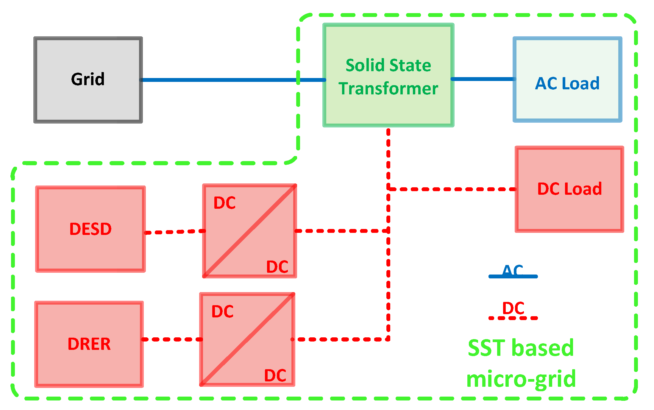
- Smart grid integrationAnother application of SST is the integration of micro-grids into the smart grid. The DC link in the SST topologies is greatly utilized in these applications. The integration of renewable energy resources (DRER) and distributed energy storage devices (DESD) is the most desirable application of SST, as the micro-grid structure is a suitable alternative to fulfill the energy demand [9]. An SST base micro-grid structure is presented in Figure 9.A quad-active-bridge (QAB) converter is proposed in the paper [75] as the fundamental component of an MMC-based SST for integrating DER and distributed energy storage systems (DESS) in the distribution grid. The DC link in SST eliminates certain frequency and phase requirements, which were fundamental in AC while integrating. Enabling bi-directional power flow is yet another advantage of SST [16,76,77]. The behavior of one such SST is investigated in [78]. The system of 100 kVA Transformer less Intelligent Power Substation (TIPS) in the paper is investigated when it is integrated with the DESD modeled through a battery.Electric vehicles (EV), as the future of automobiles, require charging stations for their implementation. These charging stations will enable the integration of electric vehicles into the grid when they are plugged into charging. The paper in [79] presents a review of the charging techniques of EV and proposes an on-road charging system with energized lanes for EV. This will allow them to draw power from the grid, raising concerns regarding its impact on the power grid. However, such charging stations are being implemented utilizing SSTs and have shown much progress and high efficiency compared to other alternatives [80].Harmonic filtering is another feature that will aid the integration of various sources and devices. The capability of harmonic filtering depends on the switching frequency of the SST [17]. The SST can also be used as the unified power quality conditioner (UPQC) to eliminate both the shunt and series transformers.
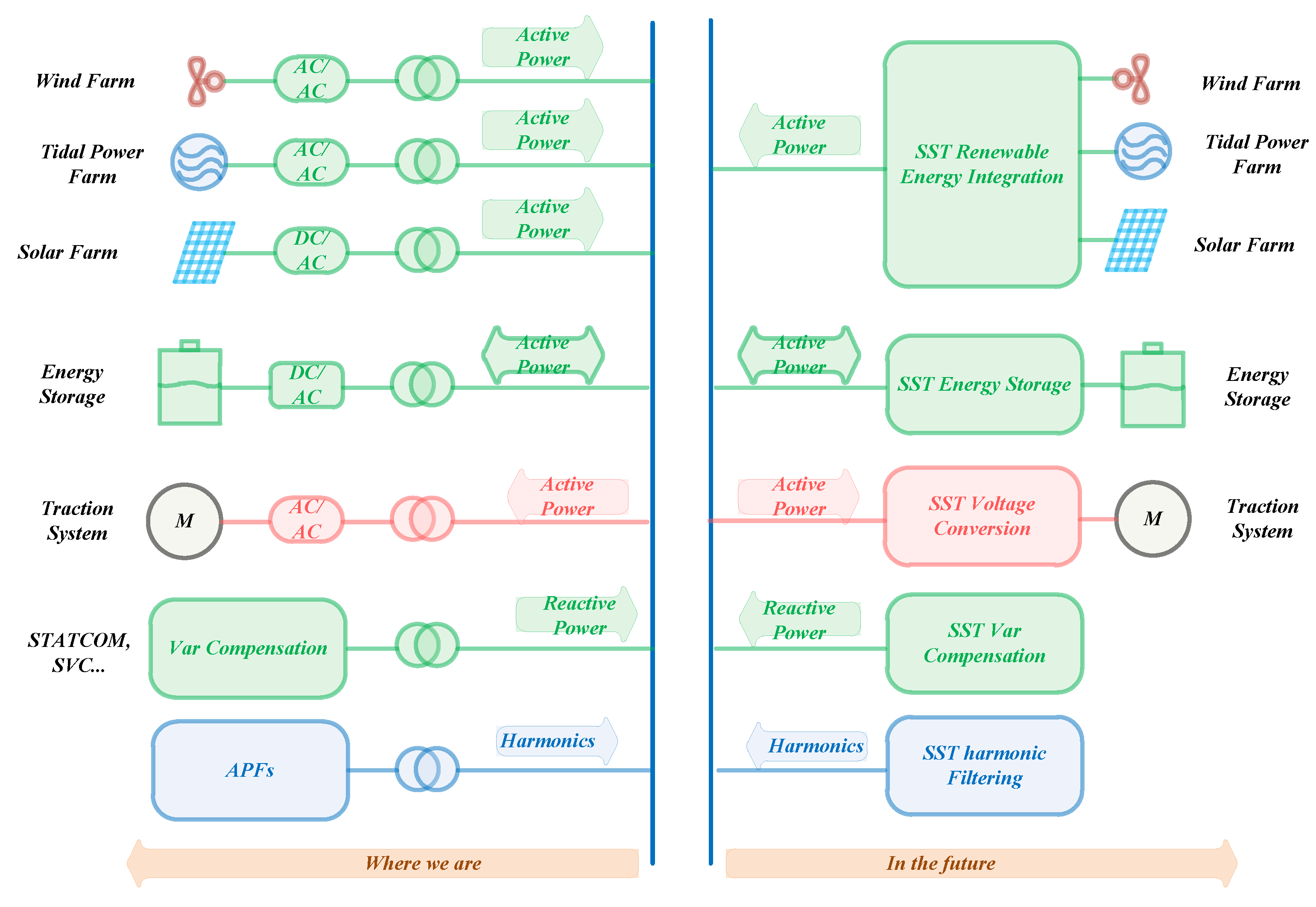
- Reactive Power CompensationUnlike conventional devices that only utilize passive components, power electronic devices employ active components. These active counterparts draw active and reactive power from the grid, which causes an imbalance between them. Although the tap-changing option of the LFT allows the transformer to control the voltage to meet the active power demands, it has limitations of margin voltage and the inability to change the frequency of the tap changers [81]. The traditional transformer is unable to compensate for the reactive power loss. Therefore, the power engineers employ the capacitor banks, Static VAr Compensators (SVCs), Static Synchronous Compensators (STATCOMs), etc., to compensate for this deficit [82]. The balance between active and reactive power is essential to regulate power flow and improve the power factor.SSTs can enhance reactive power compensation along with further reducing its power loss and cost [83]. In [84], SST based on a doubly fed induction generator (DFIG) topology has been proposed for reactive power compensation, eliminating reactive power compensator devices. In [85], system utilizing SST in the wind energy system is presented. It offers a family of wind energy systems utilizing SST, which enables control of active power and compensation of reactive power along with improved voltage regulation. It presents a simulation study for a wind farm (WF) driven by squirrel-cage induction generators is, and the wind energy system interfaced by SST is shown in Figure 10.
- Fault Isolation and LimitationTraditionally in medium-voltage AC power systems, mechanical circuit breakers clear and isolate faults enabling the continuous power supply. Although they are fast-acting and effective, the power interruption for critical loads is inevitable. SST, being an intelligent equipment, can isolate the loads from fluctuations and fault disturbances by supplying the power from micro-grid structures to maintain uninterrupted power supply to crucial loads [17]. For improvising the fault-tolerant capability of SST, an approach is proposed and validated in [86] that utilizes the time before restoration to analyze current and voltage deviations. A solid-state fault isolation device (FID) is capable of being a recloser as well as a sectionalizer. Its usage for short circuit current has already been verified [87]. Another solid-state fault isolation device (SSFID) is proposed, validated, and tested in [87]; elaborates the criteria for the selection of a solid-state fault isolation device (FID) to be used in power-electronic based distribution systems (PEDS) and draws a contrast between the fault isolation power electronics-based system (PEDS) and the traditional distribution system. It proposes and validates an FID topology, and the snubber circuit design of a 6.5 kV FID is presented.
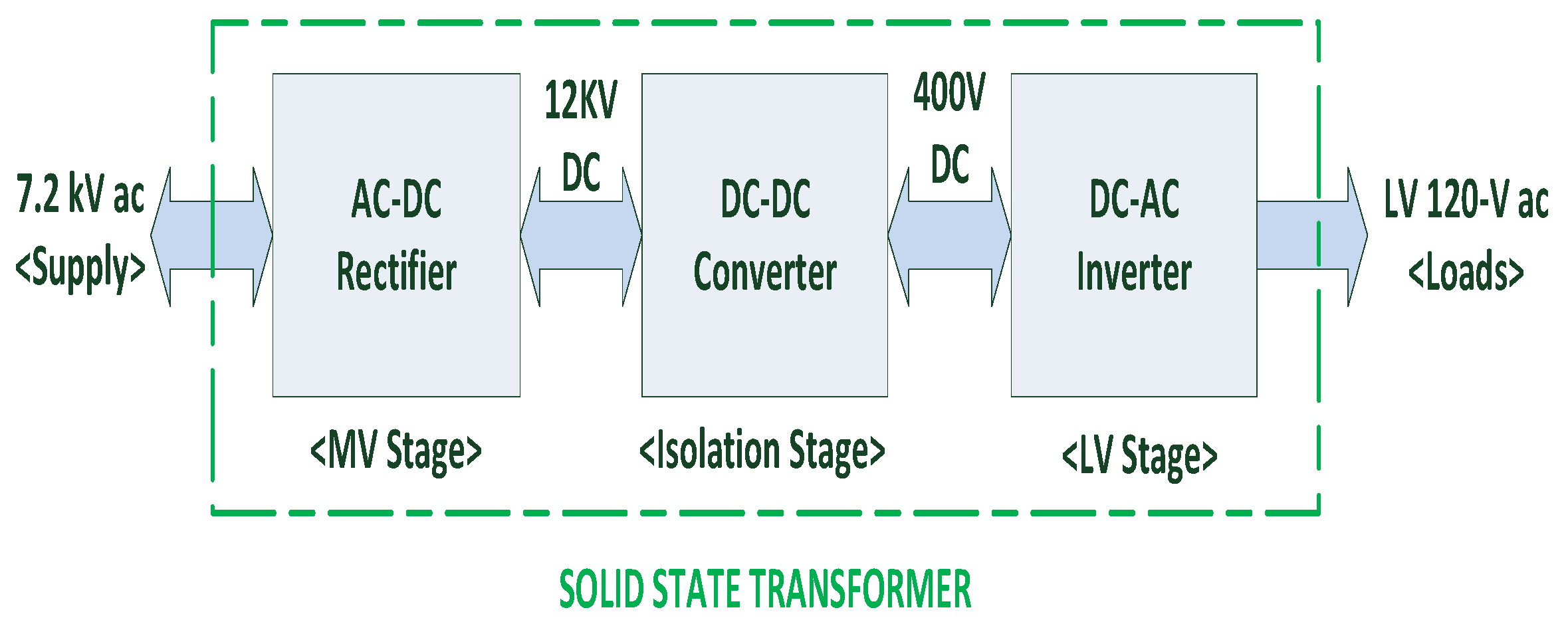
- Voltage RegulationThe voltage regulation is the essential characteristic of any basic SST. Most of the SST topology offers an AC to DC conversion stage alongside the DC capacitor. This rectifier stage allows any AC input voltage to be converted to DC, which can be controlled at this stage through power-width modulation. The PWM rectifier can boost the DC voltage keeping the power factor unity. Then, this DC voltage is converted back to AC at any desired voltage level and frequency to be supplied as output. The utilization of the PWM rectifier makes the output voltage unaffected by any voltage dip and sag in supply and allows regulated voltage supply and controllability. Additionally, the output voltage wave will be free of harmonics and purely sinusoidal with a unity power factor providing almost ideal voltage regulation [88]. A 20 kVA SST with an input voltage of 7.2 kV, 60 Hz, and output voltage of 120/240 V, 60 Hz is modeled and tested under load change test in [89] to study voltage regulation. On the other hand, [90] proposes a generalized model of SST in which by controlling the individual voltage ports of the SST voltage as well as power can be regulated more effectively and flexibly.
- HVDC TransmissionHVDC transmission offers various advantages over AC transmission, as it is independent of any voltage, frequency, and phase requirements associated with transmission and synchronization of AC. Heating loss due to harmonics will be eliminated along with other advantages as well. In the past, the generation of high voltage DC was still a concern, and then its utilization also faced many hurdles as most of the appliances operated on AC. SST suitably provides a solution to it through the DC link utilized in its topologies [91]. It also uses power electronic devices to convert AC and DC interchangeably. The HVDC link can be greatly useful in HVDC transmission. The LVDC link can improve the accessibility of DC in power systems as it facilitates the integration of devices with the grid [82]. HVDC transmission is a promising application of SST and research continues to explore its implementation in various applications. In [92], a concept for controlling and expanding the HVDC transmission was proposed, enforced by the simulation. Recently, ref [93] investigated the SST applied for the HVDC transmission from the offshore windfarm. A 200 V, 5 kVA, 3 kHz middle-frequency transformer for solid-state transformer with amorphous and nanocrystalline core materials are tested and analyzed. A Fault-tolerant Cell Design for MMC-based Multiport Power Converters was proposed in [94] to overcome the fault-tolerant capability of MMCs. The proposed cell structure, capable of blocking the DC short circuit current, is deemed feasible for the application of HVDC transmission.Various other applications of SST include energy router in future smart grids, the interface of hybrid DC and AC micro-grid systems, induction heating applications, single-stage bidirectional SST for lighting, implementation in wind energy power plant, regulating bi-directional power from micro-grid structures, interphase AC conversion, i.e., three-phase to single-phase or vice versa along with other conversions, smart regulation at the domestic level, etc.
5. Future Challenges
- CostThe cost of SST is relatively much higher than that of LFT [95]. The major part of SSTs cost is its passive components like a high-frequency transformer and heat sinks. The control circuitry is expensive as well. With the evolution of SST for specific applications, particular specially designed circuitry will be inevitably used, further contributing to its higher price. The authors of [85] provide the cost breakdown for the proposed prototype of estimated USD 10726, which is as follows: 15 kV IGBT and driver (32%), high-frequency transformer (16%), DC capacitors (16%), heat sink and fan (9%), controller board (8%), IPM and driver (7%), filter inductor (5%), sensors (4%), auxi-power supply (1%), and others (2%). Notably, the major contribution is of high voltage power devices, high-frequency transformers, and DC capacitors. It is estimated that the cost of production of 20 kVA, 7.2 kV–120 V SST is about USD 1000–2000, and the market price will be much higher. However, the market price for a single-phase 25 kVA, 7.2 kV–120/240 V pole mount transformer is around USD 1500. So, the cost of SST is much higher than the conventional transformers.However, speculations regarding reducing the cost of SSTs associated with mass production for wide applications are being made. The main contributor to this cost reduction will be electronic circuitry [96]. It is possible to witness a decline in the cost of SST with the development of SST technology, as innovative techniques contribute to the cost reduction. A cost-effective solution is to eliminate the current sensor in the DC/DC stage of cascaded multi-level converter utilizing the current sharing strategy. Instead, it uses the active power component of the duty cycle in the rectifier stage as the feedback signal for the power balance controller in the DC/DC stage [97]. The recent emergence of SiC technology is speculated to lower the cost of SST by reducing the number of power electronic devices. Various topologies incorporating SiC technology could be researched for effective cost reduction of SST.
- EfficiencyThe required overall standard efficiency for the distribution transformer of any power rating must be above 97%. Most traditional transformers’ usual efficiency is greater than 98%, but SSTs are not efficient enough. According to the standard for comparative evaluation of efficiencies of liquid immersed and dry-type distribution transformers, the Department of Energy (DOE) of the USA [98]. From the standard, the overall efficiency of liquid immersed transformers was 99.5%, which is relatively high. It was achieved due to effective heat transfer from the core of the transformer by using transformer oil. This high-efficiency traditional transformer is a considerable challenge and a big hurdle in the implementation of SST. SSTs utilize high power converters, which are not very efficient due to high switching frequency and the switching losses associated with it, thereby affecting the efficiency of SSTs in turn [37]. Another concern is that the efficiency of SST reduces significantly if not operated in the range around the rated load [99]. Although having efficiency satisfying the standard efficiency requirement is sufficient for SSTs, it offers additional advantages. However, it is still incomparable to the almost perfect efficiency of the liquid immersed transformer. Research is proposing the efficiency of SST in the range of 96% to 98%, but the actual realization is not yet achieved [95]. The switching losses can be reduced by the use of SiC, GaN, and wide bandgap devices instead of Si to improve the efficiency of the SST. The proper magnetic core selection is essential in improving efficiency by reducing the power losses at high frequency. Proper selection of excitation voltage waveform is significant in reducing the core losses. However, MMC can potentially generate controllable multi-level excitation ac voltage to improve efficiency [100]. Research is needed for the most suitable magnetic core material for SST.
- ReliabilityExtensive efforts were made so that LFTs have high reliability, are used extensively in harsh conditions, and require less maintenance. However, SSTs are fairly reliable but not as much as LFTs because they use more active components instead of passive components. Additionally, they need extensive and regular care [85]. Reliability depends on device rating and redundancy. For a non-redundant system, higher rating semiconductor devices mean high reliability. However, one more redundancy applied to a system will increase system reliability significantly up to a certain number for a redundant system. The application of numerous semiconductors in their various configurations increases the possibility of failure and makes it less reliable [101,102]. A reliability model was proposed in [103], in which having a higher rating and lower redundancy number make topologies sufficiently reliable. However, it is applicable only for specific topologies of SST.
- ProtectionUnder normal conditions, SST protects the load from faults, voltage sag, and fluctuations arising from the power grid. However, SST also requires protection of its own internal devices and circuitry from high current during abnormal conditions such as DC bus short circuit on the MV side [104,105,106]. SSTs are expected to withstand abnormal conditions, which include external faults, grid faults, converter level faults, DC-Bus faults, etc. Various protection schemes to tackle these situations are Short-Circuit Current Limiting Scheme, Circuit Breakers, Fuses, etc. [107]. The MV side DC bus short-circuit condition is the most dangerous, as it causes a high in-rush current in the switching devices. In [108], a DC short-circuits current limiting scheme utilizing the bi-directional switch approach was proposed to protect the system under abnormal operations.A high impedance grounded path-based method is proposed for SST in [104] for the SSTs whose MV side AFECs are made of three single-phase multi-level converters connected in star (Y) connection. However, it cannot be used if there is no common or neutral point on their MV side AC terminals. In [108], a bi-directional-switch-based approach is proposed to protect the transformer-less intelligent power substation (TIPS) system from the condition. However, the currents become uncontrolled if short-circuit occurs in the MV side AFEC due to its internal switching device failure. A wide range of protection schemes is available depending on various factors such as configurations, device ratings, type of faults, etc. Further studies need to explore the better protection schemes capable of protecting from a wide range of faults.
- CompatibilityThe current distribution grid was developed extensively for utilizing LFTs. From the transmission and distribution of electric power to solving various issues, the whole power system is entirely compatible with LFT. However, with SST implementation, changes must be made to the grid infrastructure to accommodate its requirements and achieve a smart grid. Changing the whole grid infrastructure is improbable and cost-ineffective; however, implementing the SSTs in a micro-grid is a better approach to slowly replacing the LFTs [109]. In [110], the design and performance of a 3.6 kV–120 V/10 kVA solid SST lab prototype have been presented for smart grid applications. Emphasizing the need for the work, for facilitating the interfacing of SST with the distribution system, a new micro-grid system is proposed in [76], which integrates SST with zonal dc micro-grid. However, this system is a step forward, but it also highlights many challenges to the system integration of SST with the distribution system.In addition, SST being a new technology, it still lacks the regulatory standards for integration with the grid. Consequently, considering NBR 16149, it can only inject reactive power when 20% of active power is injected into the network [111]. Therefore, SST requires regulatory guidelines for its safe integration into the power grid.
- IsolationIsolation is yet another feature of SST that provides various benefits. Although SST provides galvanic isolation through the high-frequency transformer, which is a requirement of smart grids, it involves multiple intermediate stages; these intermediate stages reduce the efficiency [112]. Therefore, the trade-off between galvanic isolation and the high efficiency of the SST needs to be mastered.
6. Conclusions
Author Contributions
Funding
Institutional Review Board Statement
Informed Consent Statement
Data Availability Statement
Acknowledgments
Conflicts of Interest
References
- Harlow, J.H. Electric Power Transformer Engineering; CRC Press: Boca Raton, FL, USA, 2007. [Google Scholar]
- Hassan, R.; Radman, G. “Survey on Smart Grid”. In Proceedings of the Power Electronic Application Conference, IEEE Southeast Con 2010, Concord, NC, USA, 18–21 March 2010; pp. 210–213. [Google Scholar]
- Barker, P.P.; de Mello, R.W. Determining Impact of Distributed Generation on Power Systems: Part 1 Radial Distribution Systems. In Proceedings of the Power Engineering Society Summer Meeting, Seattle, WA, USA, 16–20 July 2000; Volume 3. [Google Scholar]
- Ansari, S.; Chandel, A.; Tariq, M. A Comprehensive Review on Power Converters Control and Control Strategies of AC/DC Microgrid. Available online: https://ieeexplore.ieee.org/document/9178771 (accessed on 11 November 2021).
- Tariq, M.; Maswood, A.I.; Gajanayake, C.J.; Gupta, A.K. A Lithium-ion battery energy storage system using a bidirectional isolated DC-DC converter with current mode control for More Electric Aircraft. In Proceedings of the 2016 IEEE Symposium on Computer Applications & Industrial Electronics (ISCAIE), Penang, Malaysia, 30–31 May 2016; pp. 149–154. [Google Scholar] [CrossRef]
- Elmoudi, A.; Lehtonen, M.; Nordman, H. Effect of Harmonics on Transformers Loss of life. In Proceedings of the IEEE International Symposium on Electrical Insulation, Toronto, ON, Canada, 11–14 June 2006. [Google Scholar]
- Beig, A.R.; Ranganathan, V.T. Influence of placement of small space vectors on the performance of PWM techniques for three level inverters. In Proceedings of the IECON’03. 29th Annual Conference of the IEEE Industrial Electronics Society (IEEE Cat. No.03CH37468), Roanoke, VA, USA, 2–6 November 2003; Volume 3, pp. 2764–2770. [Google Scholar] [CrossRef]
- Carrasco, J.M.; Franquelo, L.G.; Bialasiewicz, J.T.; Galvan, E.; Guisado, R.C.P.; Prats, M.A.M.; Leon, J.I.; Moreno-Alfonso, N. Power Electronic Systems for the Grid integration of Renewable Energy Sources: A survey. IEEE Trans. Ind. Electron. 2006, 53, 1002–1016. [Google Scholar] [CrossRef]
- Bifaretti, S.; Zanchetta, P.; Watson, A.; Tarisciotti, L.; Clare, J.C. Advanced power electronic conversion and control system for universal and flexible power management. IEEE Trans. Smart Grid. 2011, 2, 231–243. [Google Scholar] [CrossRef]
- Zhao, T.F.; Yang, L.Y.; Wang, J.; Huang, A.Q. 270 kVA solid state transformer based on 10 kV SiC power devices. In Proceedings of the 2007 IEEE Electric Ship Technologies Symposium, Arlington, VA, USA, 21–23 May 2007; pp. 145–149. [Google Scholar]
- Ronan, E.R.; Sudhoff, S.D.; Glover, S.F.; Galloway, D.L. A power electronic-based distribution transformer. IEEE Trans. Power Deliv. 2002, 17, 537–543. [Google Scholar] [CrossRef]
- Tariq, M.; Maswood, A.I.; Gajanayake, C.J.; Ooi, G.H.; Chatterjee, P.; Madishetti, S.; Molligoda, D.A.; Gupta, A.K. Battery integration with more electric aircraft DC distribution network using phase shifted high power bidirectional DC-DC converter. In Proceedings of the 2015 IEEE PES Asia-Pacific Power and Energy Engineering Conference (APPEEC), Brisbane, QLD, Australia, 15–18 November 2015; pp. 1–5. [Google Scholar] [CrossRef]
- Wang, G.Y.; Baek, S.; Elliott, J.; Kadavelugu, A.; Wang, F.; She, X.; Dutta, S.; Liu, Y.; Zhao, T.F.; Yao, W.X.; et al. Design and hardware implementation of Gen-I silicon based solid state transformer. In Proceedings of the 2011 Twenty-Sixth Annual IEEE Applied Power Electronics Conference and Exposition (APEC), Fort Worth, TX, USA, 6–11 March 2011; pp. 1344–1349. [Google Scholar]
- Dujic, D.; Zhao, C.; Mester, A.; Steinke, J.K.; Weiss, M.; Schmid, S.L.; Chaudhuri, T.; Stefanutti, P. Power electronic traction transformer: Low voltage prototype. IEEE Trans. Power Electron. 2013, 28, 5522–5534. [Google Scholar] [CrossRef]
- Iqbal, M.T.; Tariq, M.; Ahmad, M.K.; Arif, M.S.B. Modeling, analysis and control of buck converter and Z-source converter for photo voltaic emulator. In Proceedings of the 2016 IEEE 1st International Conference on Power Electronics, Intelligent Control and Energy Systems (ICPEICES), Delhi, India, 4–6 July 2016; pp. 1–6. [Google Scholar] [CrossRef]
- Huang, A.Q.; Crow, M.L.; Heydt, G.T.; Zheng, J.P.; Dale, S.J. The future renewable electric energy delivery and management system: The energy internet. Proc. IEEE 2011, 99, 133–148. [Google Scholar] [CrossRef]
- She, X.; Burgos, R.; Wang, G.Y.; Wang, F.; Huang, A.Q. Review of solid state transformer in the distribution system: From implementation to filed application. In Proceedings of the 2012 IEEE Energy Conversion Congress and Exposition (ECCE), Raleigh, NC, USA, 15–20 September 2012; pp. 4077–4084. [Google Scholar]
- She, X.; Huang, A.Q.; Wang, G.Y. 3-D space modulation with voltage balancing capability for a cascaded seven level converter in a solid state transformer. IEEE Trans. Power Electron. 2011, 26, 3778–3789. [Google Scholar] [CrossRef]
- Iqbal, M.T.; Maswood, A.I.; Yeo, K.; Tariq, M. Dynamic Model and Analysis of Three phase YD Transformer Based Dual Active Bridge Using Optimised Harmonic Number for Solid State Transformer in Distributed System. In Proceedings of the 2018 IEEE Innovative Smart Grid Technologies—Asia (ISGT Asia), Singapore, 22–25 May 2018; pp. 523–527. [Google Scholar] [CrossRef]
- Iqbal, M.; Maswood, A.I.; Khan, M.S.; Tariq, M. Unified harmonic based power calculation for the bidirectional dual active bridge. Electron. Lett. 2018, 54, 1137–1139. [Google Scholar] [CrossRef]
- Khan, M.S.U.; Maswood, A.I.; Tafti, H.D.; Roomi, M.M.; Tariq, M. Control of bidirectional DC/DC converter for back to back NPC-based wind turbine system under grid faults. In Proceedings of the 2016 4th International Conference on the Development in the in Renewable Energy Technology (ICDRET), Dhaka, Bangladesh, 7–9 January 2016; pp. 1–6. [Google Scholar] [CrossRef]
- Kang, M.; Enjeti, P.N.; Pitel, I.J. Analysis and design of electronic transformers for electric power distribution system. IEEE Trans. Power Electron. 1999, 14, 1133–1141. [Google Scholar] [CrossRef]
- Khan, S.; Mahmood, A.; Tariq, M.; Zaid, M.; Khan, I.; Rahman, S. Improved Dual Switch Non-Isolated High Gain Boost Converter for DC microgrid Application. In Proceedings of the 2021 IEEE Texas Power and Energy Conference (TPEC), College Station, TX, USA, 2–5 February 2021; pp. 1–6. [Google Scholar] [CrossRef]
- Ullah, K.M.S.; Roomi, M.M.; Tariq, M.; Zhao, B. A Unity Power Factor Rectifier based Dynamic Voltage Restorer for Microgrid Applications. In Proceedings of the 2020 IEEE 17th India Council International Conference (INDICON), New Delhi, India, 10–13 December 2020; pp. 1–6. [Google Scholar] [CrossRef]
- Dohn, R.L. The Business Case for Microgrids; Siemens AG: Berlin, Germany, 2011. [Google Scholar]
- Bosich, D.; Vicenzutti, A.; Pelaschiar, R.; Menis, R.; Sulligoi, G. Toward the future: The MVDC large ship research program. In Proceedings of the 2015 AEIT International Annual Conference (AEIT), Naples, Italy, 14–16 October 2015; pp. 1–6. [Google Scholar]
- Doerry, N. Next generation integrated power systems (NGIPS) for the future fleet. In Proceedings of the IEEE Electric Ship Technologies Symposium, Baltimore, MD, USA, 20–22 April 2009; pp. 1–27. [Google Scholar]
- Devold, H. Subsea high power long offset electrical power systems. In Proceedings of the US-Norway Oil & Gas Technology Partnership Conference, Houston, TX, USA, March 2014; 2014. Available online: http://goo.gl/7tWyFc (accessed on 11 November 2021).
- Dekka, A.; Beig, A.R.; Kanukollu, S.; al Rahis, M.S. Retrofitting of Harmonic Power Filters in Onshore Oil Drilling Rigs: Challenges and Solutions. IEEE Trans. Ind. Appl. 2014, 50, 142–154. [Google Scholar] [CrossRef]
- Steiner, M.; Reinold, H. Antriebsschaltungfür ein Schienenfahrzeug. German Patent DE 198 27 872 A 1, 23 June 1998. [Google Scholar]
- Engel, B.; Victor, M.; Bachmann, G.; Falk, A. 15 kV/16.7 Hz energy supply system with medium frequency transformer and 6.5 kV IGBTs in resonant operation. In Proceedings of the 10th European Conference Power Electronics and Applications, Toulouse, France, 2–4 September 2003; pp. 1–10. [Google Scholar]
- Kalvelage, G.; Aubin, P.; Coyaud, M. KATIUMTM New power electronic topology that allows reduction of mass and volume and provides a power electronic fault tolerant system. In Proceedings of the PCIM Power Electronics Conference, Nuremberg, Germany, 2005; pp. 760–765. [Google Scholar]
- Taufiq, J. Power electronics technologies for railway vehicles. In Proceedings of the 2007 Power Conversion Conference, Nagoya, Japan, 2–5 April 2007; pp. 1388–1393. [Google Scholar]
- Steiner, M.; Reinold, H. Medium frequency topology in railway applications. In Proceedings of the 2007 European Conference on Power Electronics and Applications, Aalborg, Denmark, 2–5 September 2007; pp. 1–10. [Google Scholar]
- Zhao, C.; Dujic, D.; Mester, A.; Steinke, J.K.; Weiss, M.; Lewdeni-Schmid, S.; Chaudhuri, T.; Stefanutti, P. Power electronic traction transformer—Medium voltage prototype. IEEE Trans. Ind. Electron. 2014, 61, 3257–3268. [Google Scholar] [CrossRef]
- Gerster, C. Smart transformers for traction: Status and challenges. In Proceedings of the ECPE Workshop on Smart Transformers for Traction and Future Grid Applications, Zurich, Switzerland, 4–5 February 2016. [Google Scholar]
- Huber, J.E.; Kolar, J.W. Solid-State Transformers: On the Origins and Evolution of Key Concepts. IEEE Ind. Electron. Mag. 2016, 10, 19–28. [Google Scholar] [CrossRef]
- Brooks, J.L. Solid state transformer concept development. In Naval Material Command; Civil Eng. Lab., Naval Construction Battalion Center: Port Hueneme, CA, USA, 1980. [Google Scholar]
- McMurray, W. Multipurpose power converter circuits. U.S. Patent 3 487 289, 30 December 1969. [Google Scholar]
- McMurray, W. The thyristor electronic transformer: A power converter using a high-frequency link. IEEE Trans. Ind. Gen. Appl. 1971, IGA-7, 451–457. [Google Scholar] [CrossRef]
- McMurray, W. Fast response stepped-wave switching power converter circuit. U.S. Patent 3 581 212, 25 May 1971. [Google Scholar]
- McMurray, W. Power converter circuits having a high frequency link. U.S. Patent 3 517 300, 23 June 1970. [Google Scholar]
- Huang, A.Q. Medium-voltage solid-state transformer. IEEE Ind Electron Mag. 2016, 10, 29–42. [Google Scholar] [CrossRef]
- Hengsi, Q.; Kimball, J.W. AC-AC dual active bridge converter for solid state transformer. In Proceedings of the 2009 IEEE Energy Conversion Congress and Exposition, San Jose, CA, USA, 20–24 September 2009; pp. 3039–3044. [Google Scholar]
- Qin, H.; Kimball, J.W. Solid-State Transformer Architecture Using AC–AC Dual-Active-Bridge Converter. IEEE Trans. Ind. Electron. 2013, 60, 3720–3730. [Google Scholar] [CrossRef]
- Chen, H.; Prasai, A.; Divan, D. Dyna-C: A Minimal Topology for Bidirectional Solid-State Transformers. IEEE Trans. Power Electron. 2017, 32, 995–1005. [Google Scholar] [CrossRef]
- Masoum, A.S.; Hashemnia, N.; Abu-Siada, A.; Masoum, M.A.S.; Islam, S.M. Online Transformer Internal Fault Detection Based on Instantaneous Voltage and Current Measurements Considering Impact of Harmonics. IEEE Trans. Power Deliv. 2017, 32, 587–598. [Google Scholar] [CrossRef]
- Sabahi, M.; Hosseini, S.H.; Sharifian, M.B.; Goharrizi, A.Y.; Gharehpetian, G.B. Bi-directional power electronic transformer with maximum power-point tracking capability for induction heating applications. IET Power Electron. 2010, 3, 724–731. [Google Scholar] [CrossRef]
- Chen, H.; Divan, D. Soft-switching solid state transformer (S4T). IEEE Energy Convers. Congr. Expo. (ECCE) 2017, 33, 2933–2947. [Google Scholar]
- Liu, Y.; Liu, Y.; Ge, B.; Abu-Rub, H. Interactive grid interfacing system by matrix-converter based solid state transformer with model predictive control. IEEE Trans. Ind. Inform. 2017, 16, 2533–2541. [Google Scholar] [CrossRef]
- Sun, X.; Wang, H.; Qi, L.; Liu, F. Research on Single-Stage High-Frequency-Link SST Topology and Its Optimization Control. IEEE Trans. Power Electron. 2020, 35, 8701–8711. [Google Scholar] [CrossRef]
- Cha, H.J.; Enjeti, P.N. A three-phase AC/AC high-frequency link matrix converter for VSCF applications. In Proceedings of the 2003 IEEE 34th Annual Power Electronics Specialist Conference, Acapulco, Mexico, 15–19 June 2003; Volume 1974, pp. 1971–1976. [Google Scholar]
- Jin, A.; Li, H.; Li, S. A New Matrix Type Three-Phase Four-Wire Power Electronic Transformer. In Proceedings of the 2006 37th IEEE Power Electronics Specialists Conference, Jeju, Korea, 18–22 June 2006; pp. 1–6. [Google Scholar]
- Casarin, J.; Ladoux, P.; Martin, J.; Chauchat, B. AC/DC converter with medium frequency link for railway traction application. Evaluation of semiconductor losses and operating limits. In Proceedings of the SPEEDAM 2010, Pisa, Italy, 14–16 June 2010; pp. 1706–1711. [Google Scholar]
- Sabahi, M.; Hosseini, S.H.; Sharifian, M.B.; Goharrizi, A.Y.; Gharehpetian, G.B. Zero-voltage switching bi-directional power electronic transformer. IET Power Electron. 2010, 3, 818–828. [Google Scholar] [CrossRef]
- Yun, H.J.; Kim, H.S.; Ryu, M.H.; Baek, J.W.; Kim, H.J. A simple and practical voltage balance method for a solid-state transformer using cascaded H-bridge converters. In Proceedings of the 9th International Conference on Power Electronics (ICPE), Seoul, Korea, 1–5 June 2015; pp. 2415–2420. [Google Scholar]
- Bhaskar, R.; Agarwal, V. Dual pid loop controller for HF link inverter in two-stage SST. In Proceedings of the 2016 IEEE 7th Power India International Conference (PIICON), Bikaner, India, 25–27 November 2016; pp. 1–4. [Google Scholar] [CrossRef]
- Madhusoodhanan, S.; Tripathi, A.; Patel, D.; Mainali, K.; Kadavelugu, A.; Hazra, S.; Bhattacharya, S.; Hatua, K. Solid-State Transformer and MV Grid Tie Applications Enabled by 15 kV SiC IGBTs and 10 kV SiC MOSFETs Based Multi-level Converters. IEEE Trans. Ind. Appl. 2015, 51, 3343–3360. [Google Scholar] [CrossRef]
- Madhusoodhanan, S.; Mainali, K.; Tripathi, A.; Patel, D.; Kadavelugu, A.; Bhattacharya, S.; Hatua, K. Harmonic Analysis and Controller Design of 15 kV SiC IGBT Based Medium Voltage Grid Connected Three-Phase Three Level NPC Converter. IEEE Trans. Power Electron. 2016, 32, 3355–3369. [Google Scholar] [CrossRef]
- Mostafa, M.A.; Abdou, A.F.; Abd El-Gawad, A.F.; El-Kholy, E.E. SBO based selective harmonic elimination for nine levels asymmetrical cascaded H-bridge multi-level inverter. Aust. J. Electr. Electron. Eng. 2018, 15, 131–143. [Google Scholar] [CrossRef]
- Mostafa, M.A.; Abdou, A.F.; El-Gawad, A.F.A.; El-kholy, E.E. Comparison of multi-carrier and SHE-PWM for a nine levels cascaded H bridge inverter. In Proceedings of the 2017 Nineteenth International Middle East Power Systems Conference (MEPCON), Cairo, Egypt, 19–21 December 2017; pp. 1483–1491. [Google Scholar]
- Falcones, S.; Mao, X.; Ayyanar, R. Topology comparison for Solid State Transformer implementation. In Proceedings of the IEEE PES General Meeting, Minneapolis, MN, USA, 25–29 July 2010; pp. 1–8. [Google Scholar]
- Qin, H.; Kimball, J.W. A comparative efficiency study of silicon-based solid state transformers. In Proceedings of the 2010 IEEE Energy Conversion Congress and Exposition, Atlanta, GA, USA, 12–16 September 2010; pp. 1458–1463. [Google Scholar]
- Zhang, J.; Wang, Z.; Shao, S. A three-phase modular multilevel DC–DC converter for power electronic transformer applications. IEEE J. Emerg. Sel. Top. Power Electron. 2017, 5, 140–150. [Google Scholar] [CrossRef]
- Zhang, C.; Wang, H.; Peng, J.; Yu, J. Control of Three-Stage AC-AC Solid State Transformer for Power Exchange Between Grids. In Proceedings of the 2019 IEEE PES Asia-Pacific Power and Energy Engineering Conference (APPEEC), Macao, China, 1–4 December 2019; pp. 1–5. [Google Scholar] [CrossRef]
- Abu-Siada, A.; Budiri, J.; Abdou, A.F. Solid State Transformers Topologies, Controllers, and Applications: State-of-the-Art Literature Review. Electronics 2018, 7, 298. [Google Scholar] [CrossRef] [Green Version]
- Drabek, P.; Peroutka, Z.; Pittermann, M.; Cedl, M. New configuration of traction converter with medium frequency transformer using matrix converters. IEEE Trans. Ind. Electron. 2011, 58, 5041–5048. [Google Scholar] [CrossRef]
- Komrska, T.; Peroutka, Z. Main traction converter with medium frequency transformer: Control of converters around MF transformer. In Proceedings of the 2008 International Symposium on Power Electronics, Electrical Drives, Automation and Motion, Ischia, Italy, 11–13 June 2008; pp. 1194–1198. [Google Scholar]
- Hugo, N.; Stefanutti, P.; Pellerin, M.; Akdag, A. Power electronic traction transformer. In Proceedings of the EPE, Birmingham, UK, 5 October 2007; pp. 1–10. [Google Scholar]
- Carpita, M.; Marchesoni, M.; Pellerin, M.; Moser, D. Multi-level converter for traction applications: Small-scale prototype test results. IEEE Trans. Ind. Electron. 2008, 55, 2203–2212. [Google Scholar] [CrossRef]
- Glinka, M.; Marquardt, R. A new AC/AC multi-level converter family. IEEE Trans. Ind. Electron. 2005, 52, 662–669. [Google Scholar] [CrossRef]
- Claessens, M.; Dujic, D.; Steinke, J.K.; Stefanutti, P.; Vetterli, C. Traction transformation: A power electronic traction transformer (PETT). ABB Rev. 2012, 3, 1–3. [Google Scholar]
- Zhang, J.; Liu, J.; Zhong, S.; Yang, J.; Zhao, N.; Zheng, T.Q. A Power Electronic Traction Transformer Configuration with Low-Voltage IGBTs for Onboard Traction Application. IEEE Trans. Power Electron. 2019, 34, 8453–8467. [Google Scholar] [CrossRef]
- Pacheco, J.D.O.; Honório, D.D.A.; Oliveira, D.D.S. An AC–DC Isolated MMC-Based Structure Suitable for MV SST Traction Applications. IEEE Access 2019, 7, 106395–106406. [Google Scholar] [CrossRef]
- Frutos, P.; Briz, F.; Sánchez, A.; Guerrero, J.M. Quad-Active-Bridge as the basic cell of a MMC Based SST for DER and DESS Integration. In Proceedings of the 2019 IEEE 28th International Symposium on Industrial Electronics (ISIE), Vancouver, BC, Canada, 12–14 June 2019; pp. 2349–2355. [Google Scholar] [CrossRef]
- She, X.; Huang, A.Q.; Lukic, S.; Baran, M. On integration of solid state transformer with zonal DC microgrid. IEEE Trans. Smart Grid. 2012, 3, 975–985. [Google Scholar] [CrossRef]
- She, X.; Lukic, S.; Huang, A.Q.; Bhattacharya, S.; Baran, M. Performance evaluation of solid state transformer based microgrid in FREEDM systems. In Proceedings of the 2011 Twenty-Sixth Annual IEEE Applied Power Electronics Conference and Exposition (APEC), Fort Worth, TX, USA, 6–11 March 2011; pp. 182–188. [Google Scholar]
- Madhusoodhanan, S.; Tripathi, A.; Mainali, K.; Patel, D.; Kadavelugu, A.; Bhattacharya, S. Distributed Energy Storage Device integration with three phase distribution grid using a Transformerless Intelligent Power Substation. In Proceedings of the 2015 IEEE Applied Power Electronics Conference and Exposition (APEC), Charlotte, NC, USA, 15–19 March 2015; pp. 670–677. [Google Scholar] [CrossRef]
- Tudorache, T.; Marinescu, A.; Dumbrava, I. On-road Charging System Demonstrator for EVs. In Proceedings of the 2019 Electric Vehicles International Conference (EV), Bucharest, Romania, 3–4 October 2019; pp. 1–4. [Google Scholar] [CrossRef]
- Pool-Mazun, E.I.; Sandoval, J.J.; Enjeti, P.N.; Pitel, I.J. An Integrated Solid State Transformer (I-SST) with High-Frequency Isolation for EV Fast-Charging Applications. IEEE J. Emerg. Sel. Top. Ind. Electron. 2020, 1, 46–56. [Google Scholar] [CrossRef]
- Borgaonkar, A. Solid State Transformers: A Review of Technology and Applications. Indian Inst. Technol. 2015. [Google Scholar] [CrossRef]
- Kadandani, N.B.; Dahidah, M.; Ethni, S.; Yu, J. Solid state transformer: An overview of circuit configurations and applications. In Proceedings of the 15th IET International Conference on AC and DC Power Transmission (ACDC 2019), Coventry, UK, 5–7 February 2019; pp. 1–6. [Google Scholar] [CrossRef] [Green Version]
- Shen, Z.; Wang, Z.; Baran, M.E. Optimal volt/var control strategy for distribution system with multiple voltage regulating devices. In Proceedings of the PES T&D 2012, Orlando, FL, USA, 7–10 May 2012; pp. 1–7. [Google Scholar] [CrossRef]
- Verma, N.; Singh, N.; Yadav, S.; Gupta, S. Reactive Power Compensation of Solid State Transformer for WECS. In Proceedings of the 2018 2nd International Conference on Electronics, Materials Engineering & Nano-Technology (IEMENTech), Kolkata, India, 4–5 May 2018; pp. 1–6. [Google Scholar] [CrossRef]
- She, X.; Huang, A.Q.; Wang, F.; Burgos, R. Wind Energy System with Integrated Functions of Active Power Transfer, Reactive Power Compensation, and Voltage Conversion. IEEE Trans. Ind. Electron. 2013, 60, 4512–4524. [Google Scholar] [CrossRef]
- Gorla, N.B.Y.; Kolluri, S.; Chauhan, P.J.; Panda, S.K. A fault tolerant control approach for a three-stage cascaded multi-level solid state transformer. In Proceedings of the 2017 IEEE 18th Workshop on Control and Modeling for Power Electronics (COMPEL), Stanford, CA, USA, 9–12 July 2017; pp. 1–6. [Google Scholar] [CrossRef]
- Vodyakho, O.; Steurer, M.; Edrington, C.; Karady, G.; Bhattacharya, S. Instantiation of solid state fault isolation devices for future power electronic based distribution systems. In Proceedings of the IEEE PES General Meeting, Minneapolis, MN, USA, 25–29 July 2010; pp. 1–8. [Google Scholar] [CrossRef]
- Kikuchi, J.; Lipo, T.A. Three-phase PWM boost-buck rectifiers with power-regenerating capability. IEEE Trans. Ind. Appl. 2002, 38, 1361–1369. [Google Scholar] [CrossRef] [Green Version]
- Maharjan, M.; Tamrakar, U.; Bajagain, S.; Hansen, T.M.; Tonkoski, R. A steady-state equivalent model of solid state transformers for voltage regulation studies. In Proceedings of the 2017 IEEE Power & Energy Society General Meeting, Chicago, IL, USA, 16–20 July 2017; pp. 1–5. [Google Scholar] [CrossRef]
- Liu, X.; Liu, Y.; Liu, J.; Zhang, X. Coordinating voltage regulation for an AC–DC hybrid distribution network with multiple SSTs. J. Eng. 2019, 2019, 1368–1372. [Google Scholar] [CrossRef]
- Jianyang, Y.; Khan, M.Q.; Yanwen, Z.; Khan, M.M.; Ali, M. HVDC bidirectional power flow using solid state transformer. In Proceedings of the 2017 International Conference on Circuits, Devices and Systems (ICCDS), Chengdu, China, 5–8 September 2017; pp. 110–114. [Google Scholar] [CrossRef]
- Zhao, H.; Yang, B. A Novel Conception for HVDC Transmission Capacity Expansion and Its Control Strategy. In Proceedings of the 2018 IEEE International Power Electronics and Application Conference and Exposition (PEAC), Shenzhen, China, 4–7 November 2018; pp. 1–6. [Google Scholar] [CrossRef]
- Kimura, N.; Morizane, T.; Iyoda, I.; Nakao, K.; Yokoyama, T. Application of Solid-State Transformer for HVDC Transmission from Offshore Windfarm. In Proceedings of the 2018 7th International Conference on Renewable Energy Research and Applications (ICRERA), Paris, France, 14–17 October 2018; pp. 902–907. [Google Scholar] [CrossRef]
- Zapico, A.; Lopez, M.; Rodriguez, A.; Briz, F. Fault tolerant cell design for MMC-based multiport power converters. In Proceedings of the 2016 IEEE Energy Conversion Congress and Exposition (ECCE), Milwaukee, WI, USA, 18–22 September 2016; pp. 1–8. [Google Scholar] [CrossRef]
- She, X.; Huang, A.Q.; Burgos, R. Review of Solid-State Transformer Technologies and Their Application in Power Distribution Systems. IEEE J. Emerg. Sel. Top. Power Electron. 2013, 1, 186–198. [Google Scholar] [CrossRef]
- Gadgil, K.S. Solid State Transformers. Int. J. Adv. Res. Innov. Ideas Educ. 2016, 2, 320–324. [Google Scholar]
- She, X.; Huang, A.Q.; Ni, X. A cost effective power sharing strategy for a cascaded multilevel converter based solid state transformer. In Proceedings of the 2013 IEEE Energy Conversion Congress and Exposition, Denver, CO, USA, 15–19 September 2013; pp. 372–379. [Google Scholar]
- Federal Register, 10 CFR Part 431, Energy Conversation Program for Commercial Equipment, Distribution transformers Energy Conversation Standards; Final Rule (U.S. Department of Energy). Prepared by the Office of the Federal Register, National Archives and Records Administration (12 October 2007). Available online: https://www.federalregister.gov/documents/2007/10/12/E7-19582/energy-conservation-program-for-commercial-equipment-distribution-transformers-energy-conservation (accessed on 11 November 2021).
- Besselmann, T.; Mester, A.; Dujic, D. Power Electronic Traction Transformer: Efficiency Improvements under Light-Load Conditions. IEEE Trans. Power Electron. 2014, 29, 3971–3981. [Google Scholar] [CrossRef]
- Zhang, L.; Zhao, Z.; Qin, J. Efficiency optimization design of DC-DC solid state transformer based on modular multilevel converters. In Proceedings of the 2017 IEEE Energy Conversion Congress and Exposition (ECCE), Cincinnati, OH, USA, 1–5 October 2017; pp. 3508–3513. [Google Scholar] [CrossRef]
- EPRI (2004) Feasibility Study for the Development of High-Voltage, Low-Current Power Semiconductor Devices; EPRI Report 1001698; 2004; Available online: https://preview.epri.com/research/products/000000000001009516 (accessed on 11 November 2021).
- EPRI (2004) Development of a New Multi-Level Converter-Based Intelligent Universal Transformer: Design Analysis; EPRI Report 1002159; 2004; Available online: https://preview.epri.com/research/products/000000000001002159 (accessed on 11 November 2021).
- Wang, K.; Lei, Q.; Liu, C. Methodology of reliability and power density analysis of SST topologies. In Proceedings of the 2017 IEEE Applied Power Electronics Conference and Exposition (APEC), Tampa, FL, USA, 26–30 March 2017; pp. 1851–1856. [Google Scholar] [CrossRef]
- Guillod, T.; Krismer, F.; Kolar, J.W. Protection of mv converters in the grid: The case of mv/lv solid-state transformers. IEEE J. Emerg. Sel. Top. Power Electron. 2017, 5, 393–408. [Google Scholar] [CrossRef]
- Singh, U.; Baran, M.E. Protection of smart distribution systems with distributed energy resources and solid state transformers. In Proceedings of the 2017 IEEE Power Energy Society General Meeting, Chicago, IL, USA, 16–20 July 2017; pp. 1–5. [Google Scholar]
- Tatcho, P.; Li, H.; Jiang, Y.; Qi, L. A Novel Hierarchical Section Protection Based on the Solid State Transformer for the Future Renewable Electric Energy Delivery and Management (FREEDM) System. IEEE Trans. Smart Grid. 2013, 4, 1096–1104. [Google Scholar] [CrossRef]
- Jakka, V.N.; Acharya, S.; Anurag, A.; Prabowo, Y.; Kumar, A.; Parashar, S.; Bhattacharya, S. Protection Design Considerations of a 10 kV SiC MOSFET Enabled Mobile Utilities Support Equipment Based Solid State Transformer (MUSE-SST). In Proceedings of the IECON 2018—44th Annual Conference of the IEEE Industrial Electronics Society, Washington, DC, USA, 21–23 October 2018; pp. 5559–5565. [Google Scholar] [CrossRef]
- Madhusoodhanan, S.; Patel, D.; Bhattacharya, S.; Carr, J.A.; Wang, Z. Protection of a transformerless intelligent power substation. In Proceedings of the 2013 4th IEEE International Symposium on Power Electronics for Distributed Generation Systems (PEDG), Rogers, AR, USA, 8–11 July 2013; pp. 1–8. [Google Scholar]
- Bala, S.; Das, D.; Aeloiza, E.; Maitra, A.; Bajagopalan, S. Hybrid transformer: Concept development and filed demonstration. In Proceedings of the 2012 IEEE Energy Conversion Congress and Exposition (ECCE), Raleigh, NC, USA, 15–20 September 2012; pp. 4061–4068. [Google Scholar]
- She, X.; Yu, X.; Wang, F.; Huang, A.Q. Design and demonstration of a 3.6 kV–120 V/10 KVA solid state transformer for smart grid application. In Proceedings of the 2014 IEEE Applied Power Electronics Conference and Exposition—APEC 2014, Fort Worth, TX, USA, 16–20 March 2014; pp. 3429–3436. [Google Scholar] [CrossRef]
- Londero, R.P.; Mello, A.P.C.d.; da Silva, G.S. Comparison between conventional and solid state transformers in smart distribution grids. In Proceedings of the 2019 IEEE PES Innovative Smart Grid Technologies Conference—Latin America (ISGT Latin America), Gramado, Brazil, 15–18 September 2019; pp. 1–6. [Google Scholar] [CrossRef]
- Fan, H.; Li, H. High-Frequency Transformer Isolated Bidirectional DC–DC Converter Modules with High Efficiency over Wide Load Range for 20 kVA Solid-State Transformer. IEEE Trans. Power Electron. 2011, 26, 3599–3608. [Google Scholar] [CrossRef]


| Expandability | Capacitor Size | Inductor No. | Capacitor No. | Semiconductors No. | |
|---|---|---|---|---|---|
| Neutral point-clamped | No | Low | Low | Low | High |
| Flying capacitor | No | Low | Low | Low | Low |
| H-bridge cascaded | Yes | Medium | Low | High | Low |
| MMC | Yes | High | High | Low | Low |
Publisher’s Note: MDPI stays neutral with regard to jurisdictional claims in published maps and institutional affiliations. |
© 2021 by the authors. Licensee MDPI, Basel, Switzerland. This article is an open access article distributed under the terms and conditions of the Creative Commons Attribution (CC BY) license (https://creativecommons.org/licenses/by/4.0/).
Share and Cite
Khan, S.; Rahman, K.; Tariq, M.; Hameed, S.; Alamri, B.; Babu, T.S. Solid-State Transformers: Fundamentals, Topologies, Applications, and Future Challenges. Sustainability 2022, 14, 319. https://doi.org/10.3390/su14010319
Khan S, Rahman K, Tariq M, Hameed S, Alamri B, Babu TS. Solid-State Transformers: Fundamentals, Topologies, Applications, and Future Challenges. Sustainability. 2022; 14(1):319. https://doi.org/10.3390/su14010319
Chicago/Turabian StyleKhan, Saniya, Khaliqur Rahman, Mohd Tariq, Salman Hameed, Basem Alamri, and Thanikanti Sudhakar Babu. 2022. "Solid-State Transformers: Fundamentals, Topologies, Applications, and Future Challenges" Sustainability 14, no. 1: 319. https://doi.org/10.3390/su14010319
APA StyleKhan, S., Rahman, K., Tariq, M., Hameed, S., Alamri, B., & Babu, T. S. (2022). Solid-State Transformers: Fundamentals, Topologies, Applications, and Future Challenges. Sustainability, 14(1), 319. https://doi.org/10.3390/su14010319