Article

A Novel Z Profile of Pultruded Glass-Fibre-Reinforced Polymer Beams for Purlins

by
Djoko Setyanto
1,*,
Yohanes Adeatma Antonio
1,
Marten Darmawan
1 and
Ubaidillah Ubaidillah
2,*
1
Mechanical Engineering Department, Faculty of Engineering, Atma Jaya Catholic University of Indonesia, Jakarta 12930, Indonesia
2
Mechanical Engineering Department, Faculty of Engineering, Sebelas Maret University, Surakarta 57126, Indonesia
*
Authors to whom correspondence should be addressed.
Sustainability 2022, 14(10), 5862; https://doi.org/10.3390/su14105862
Submission received: 1 March 2022 / Revised: 1 May 2022 / Accepted: 9 May 2022 / Published: 12 May 2022
(This article belongs to the Collection Structural Sensing and Sustainable Infrastructure Maintenance)

Abstract

:
Purlins made from galvanised steel in fertiliser warehouses have often been considered less efficient, necessitating a new purlin made using corrosion-resistant material to increase building efficiency. This study was an attempt to design a nine-metre purlin from glass-fibre-reinforced polymer (GFRP) composite material for a new fertiliser warehouse in Bontang-East Kalimantan, Indonesia. The purlin design selected in this study was the Z profile of pultruded beams from GFRP composite material that met the criteria of an efficient purlin, such as corrosion resistance, compact stacking, and ability to withstand technical loads. In particular, the Z profile becomes compact when stacked, and the GFRP material used is corrosion-resistant yet affordable. The primary materials for GFRP composites consist of long yarn glass fibre bundles for reinforcement and unsaturated polyester resin (UPR) for the matrix. Material strength modelling was based on analytical and finite element approaches. The analysis shows that the most considerable normal stress of “64.41 MPa” occurred at the two fixed end supports, while the most significant deflection of “45.9 mm” occurred at the mid-span of the purlin structure. The purlin structure was considered safe, as the strength and deflection were below the threshold. Thus, the Z profile of the pultruded purlin beams built using the GFRP composite material meets the technical criteria.

1. Introduction

A purlin is a rigid beam supporting corrugated roofing sheets for warehouses and factories. The purlin span, which is generally six metres in length, is supported by two adjacent columns with a uniform cross-section of purlin beams. The cross-sectional profiles used by many industrial buildings include hat (Ω), channel (C), and zeta (Z) [1]. A purlin is primarily built from carbon steel and coated with galvanised zinc–aluminium alloy. The thickness of the galvanised layer, which functions as a corrosion-protective layer, becomes an essential factor that affects its material durability [2,3,4]. While a thicker protective layer would perform better, it would also be considerably more expensive.
Galvanised steel purlins are commonly found in warehouse and factory buildings of various industries, including the fertiliser industry. As fertiliser plants deal with corrosive substances, corrosion may occur on the galvanised steel beams, which adversely impacts the life span of the material. Hence, protecting the purlin material from the corrosive fertiliser plant environment requires regular maintenance. Coating the purlin surface with polymer layers is a popular corrosion protection mechanism [5,6]. Unfortunately, field experience indicates that this method is expensive and less effective. To address the drawbacks of galvanised steel material, glass-fibre-reinforced polymer (GFRP) is a suitable alternative for use in corrosive environments such as fertiliser plants. This material has good corrosion resistance and is relatively affordable. In addition, GFRP materials are ideal for construction in corrosive environments due to their durability and low maintenance cost [7,8,9,10,11,12,13,14,15,16,17]. Unsurprisingly, since 2011, Indonesian fertiliser industries have relied on GFRP for corrugated roofing sheets to mitigate corrosion for their warehouses and factories [18].
The choice of building materials for industry, especially in a corrosive environment such as a fertiliser factory, will affect sustainability [7,8,9,10,11,12]. Building materials with a short service life due to material degradation, apart from disrupting the production process, will also reduce the company’s efficiency. Selection of suitable materials according to environmental conditions that provide a long service life and are supported by proper factory management will contribute to energy savings and environmental sustainability [19,20,21,22].
Previous researchers have suggested that FRP composite material is the right choice to be applied as a building material in corrosive environments. GFRP material that uses unsaturated polyester resin (UPR) and E-glass as reinforcement is rational, because its technical properties can meet the requirements relatively economically [7,23,24]. As mentioned earlier, synthetic materials for matrix and reinforcement are still the leading choice today for technical and economic considerations. Synthetic fibre is preferred over natural fibre for several reasons, such as its higher mechanical properties; its availability in the market is more guaranteed on an economic scale, and it is more resistant to moisture and thermal effects [7,8]. Meanwhile, the advantages of natural fibre are its capacity to be recycled or easily decomposed in nature and the possibility of its abundant and renewable potential [25].
Previous studies on pultruded fibre-reinforced polymer (FRP) beams have also supported FRP materials for a wide range of building structures, such as bridge construction, lightweight structures, structural connectors, concrete reinforcements, emergency structures, and deck structures [7,26,27,28,29,30,31,32].
Despite the advantages of FRP materials for use in corrosive environments, there is still a dearth of research on applying pultruded GFRP as a purlin. Therefore, the present study aims to design a nine-metre corrosion-resistant purlin for a new fertiliser warehouse. The design was intended to create an optimal cross-section for a warehouse building affected by the corrosive environment in the tropics, especially in Indonesia, and more specifically, at Bontang-East Kalimantan. The aspects of optimal cross-section considered were the cross-sectional profile’s thickness, height, and width. The selection will produce a cross-sectional moment of inertia that meets the criteria for limiting deflection and flexural stress and has a minimum cross-sectional area; therefore, the beam mass becomes efficient.

2. Materials and Methods

The purlin design comprises three major stages. The first stage is determining the type and dimensions of the optimum profile based on the theoretical-analytic analysis. The second stage is producing purlins and purlin structure prototypes to assess the object feasibility. Finally, following the theoretical-numeric analysis or finite element analysis, a more detailed assessment of the strength of the material of the purlin structure was carried out to ensure its safety as a roof-supporting structure.

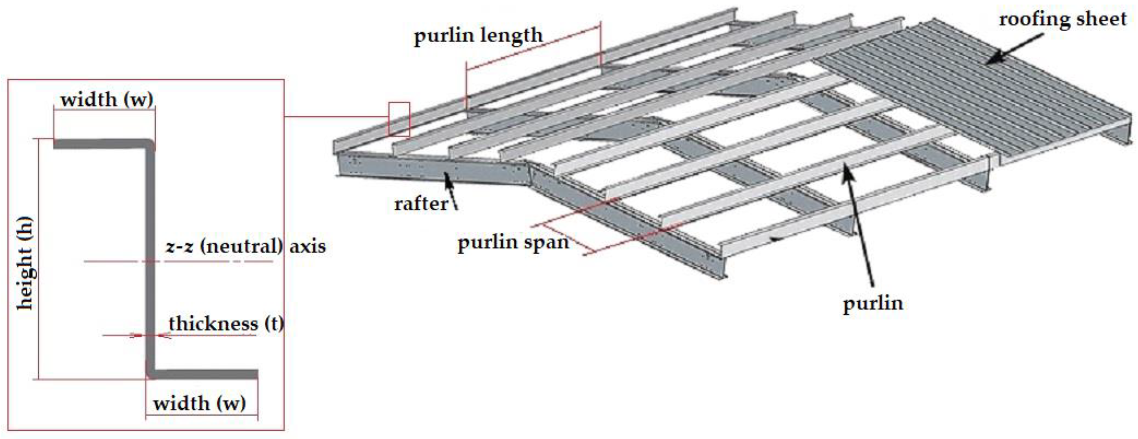
2.1. Optimum Profile of the Purlin

The product design method aimed for the optimum purlin profile, which adhered to the engineering design process [33]. The process started with the specification of the technical criteria of the purlin, followed by the establishment of the conceptual design, embodiment, and detailed design. The detailed design used a theoretical-analytic approach for the physical model of the purlin structure, as depicted in Figure 1 and Figure 2 and Equations (1)–(6).
The technical load on the purlin structure pertained to the constant distributed forces perpendicular to the longitudinal axis, consisting of (1) purlin weight, (2) weight of corrugated roofing sheet, (3) live load, (4) rain load, and (5) wind load. In this research, the loading standard refers to the Indonesian national standard, SNI 1727 (2020) [34]. The GFRP material purlin weighed about “71 N/m”, while the GFRP roofing sheets weighed about “39 N/m2”. The live load was approximated to be “958 N/m2”, the rain load was “196 N/m2”, and the wind load was “993 N/m2”. Furthermore, the distance between two purlins was estimated to be 1.6 metres. Table 1 shows the intended loads on the purlin structure.
The equations for design load (Q), bending moment (M), flexural stress (σ), shear stress (τ), and deflection (δ) were as follows:
Q = QP + QS + QL or Q = QP + QS + QR + QW; where is the biggest
M max = M A = M C = QL 2 12
σ max = M max ×   C I z z
τ = V   ×   Q I z z × t = V   × A ^   ×   y ^ I z z × t
δ B = QL 4 384 EI z z
(δ/L)allowable = 1/180
where Q is the design load (N/m), M is the bending moment (Nm), L is the purlin length (m), σ is the flexural stress (N/m2), C is the farthest point at the cross-section of the purlin and the neutral axis or z-z axis (m), Iz-z is the moment of inertia of the cross-section of the purlin and the neutral axis (m4), V is the shear force at both fixed ends of the structure (N), Q is the area moment of the z-z axis (Nm), Â is the cross-section area above or below z-z axis (m2), ŷ is the centre gravity of the cross-section area above or below z-z axis from the z-z axis (m), δ is the deflection (m), and E is the modulus of elasticity of the pultruded GFRP material in the longitudinal direction (N/m2).
The design load Q was calculated using Table 1 and Equation (1), while the maximum bending moment was calculated using Equation (2). The calculation results show that Q and Mmax were “2037 N/m” and “13,750 Nm”, respectively.
The mechanical properties of the pultruded GFRP material used as the initial reference, which will later be designed and produced, are presented in Table 2. The minimum values of the tensile strength (σt), modulus of elasticity (E), and shear strength at the longitudinal axis (τL) were “400 MPa”, “22 GPa”, and “40 MPa”, respectively [35]. As depicted in Figure 2, the purlin structure will produce one principal stress in the direction of the longitudinal axis of the purlin (x-x axis) and a deflection in the direction of the axis perpendicular to the longitudinal axis of the purlin (y-y axis). The stress and the deflection must be limited for the structure to be declared safe. Pultruded GFRP materials are brittle materials and do not have yield strength like steel. Therefore, the design stress (σd) used as a safety limit in the FE approach analysis was 80% of the tensile strength or “320 MPa”. Then, the analysis used a theoretical-analytic approach using allowable stress by taking a safety factor of 3, because this considers the stress concentration due to the bolt holes [36] at the supports at both ends of the purlin. Thus, the allowable stress (σallowable) was “106.67 MPa”. The flexural stress was calculated using Equation (3). As described above, the failure of flexural stress mode occurs at both ends of the supports. On the other hand, the failure of the shear mode is caused by shear forces at both ends of the purlin structure. The most significant shear stress will occur at the line of the neutral axis (z-z axis) and at the plane where the longitudinal axis (x-x axis) is present. Equation (4) is the formula for calculating shear stress. Maximum deflection occurs in the middle of the span of the purlin structure and is calculated by Equation (5). Referring to Table 9.5.b of ACI 318-19 [37], the magnitude of the deflection was limited to L/180, as shown in Equation (6).
Considering the determined purlin profile, some of the technical criteria considered were: (1) corrosion resistance for application in a fertiliser plant environment; (2) ability to support roofing sheets with a purlin span of nine metres and ability to withstand all technical loads from roofing sheet support structure; and (3) compact and cost-efficient handling and shipment from the purlin factory to the new warehouse project site.

2.2. Purlin Prototypes and Structures

The constituent materials used to produce the pultruded GFRP consisted of E-glass reinforcement and polymer matrix. The E-glass fibre was constructed from longitudinal bundles of Jushi 312t 4400tex ECR Glass Direct Roving (Changzhou Zhongjie Composites Co., Ltd., Changzhou, China) and four layers of “450 g/m2” stitched mat of Jushi EMK450 (Changzhou Zhongjie Composites Co., Ltd., Changzhou, China). Meanwhile, the polymer matrix was a mixture of 100 parts by weight of orthophthalic unsaturated polyester resin (UPR) SHCP 3316QN (PT SHCP Indonesia, Surabaya, Indonesia), five elements by weight of alumina trihydrate (ATH) H-WF-08A (PT Justus Kimiaraya, Jakarta, Indonesia), five parts by weight of light-grey pigments HM IP 7 (PT Mata Pelangi Chemindo, Jakarta, Indonesia), and one and a half parts by weight of catalyst benzoyl peroxide BENZOXE-N (PT Kawaguchi Kimia Indonesia, Jakarta, Indonesia). Fibre and matrix weight percentages in the composite were 55–60% and 45–40%, respectively [35]. All these materials were procured from PT Intec Persada, Indonesia.
The pultrusion method was used for manufacturing purlin prototypes, and the Songhe pultrusion machine owned by PT Intec Persada was employed. Material samples from the pultruded GFRP prototype were then examined for surface hardness and tensile and shear properties. Hardness examination was done using a Barcol hardness tester based on the ASTM D2583 standard [38]. Tensile properties in the longitudinal and transverse directions were obtained according to the ASTM D638 standard [39]. The shear strength in the longitudinal direction was measured experimentally, as shown in Figure 3. The tensile forces were applied to a sample of pultruded GFRP material through its bolt-nut holes. The longitudinal shear strength was obtained by dividing the force by two areas of shear due to the compression force of the bolt.

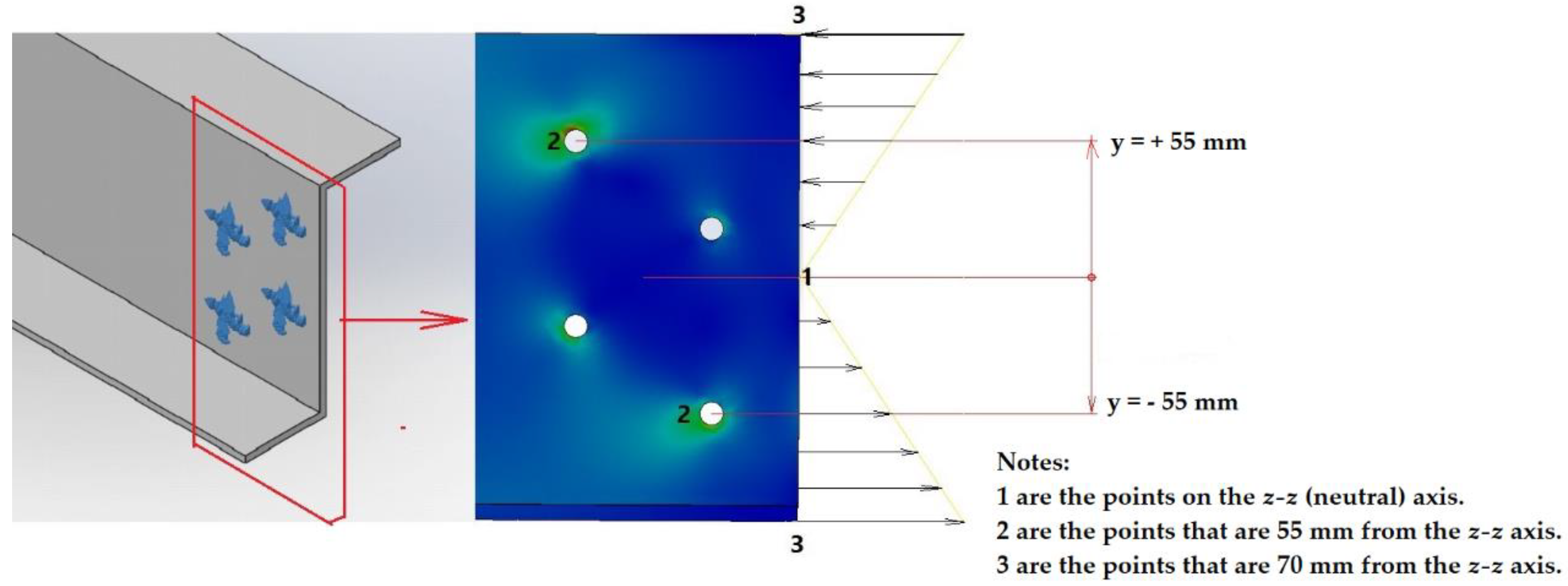
2.3. Finite Element Analysis of the Purlin Structure

The detailed material strength analysis of the purlin structure was based on a numerical approach, namely finite element analysis. The finite element (FE) model of the purlin structure is the physical model depicted in Figure 2, but the model is presented in three dimensions as a Z beam structure with a fixed clamp at both ends. Solidworks software was used to create the model. Figure 4 illustrates the finite element model of the purlin structure.
The FE model of the purlin structure in Figure 4 was developed from the FE model of the cantilever structure, as shown in Figure 5. The method was to set the beam length to 4.5 metres and reflect it on the vertical axis at the beam’s free end, as illustrated in Figure 6.
The FE model of the cantilever structure, as depicted in Figure 5, had to be validated. The validation utilised the experimental prototype of the cantilever structure shown in Figure 7. The force exerted by the hydraulic jack on the beam’s free end caused a deflection, which was then used to validate the deflection of the FE model of the cantilever beam structure.

3. Results

3.1. Purlin Profile

The conceptual design of purlin consists of three sub-functions to meet these three technical criteria, as shown in Table 3. The terms GFRP, KFRP, and CFRP in Table 3 are glass-fibre-reinforced polymer, Kevlar (or aramid)-fibre-reinforced polymer, and carbon-fibre-reinforced polymers. Meanwhile, G/K/C-FRP is a polymer reinforced by a hybrid of glass, Kevlar/aramid, and carbon fibres.
There were many variations of the conceptual design comprising combinations of the three sub-functions, including of (1) 1st conceptual design 1-1 and 2-1 and 3-1, 2nd conceptual design 1-1 and 2-1 and 3-2, 3rd conceptual design 1-1 and 2-1 and 3-3, 4th conceptual design 1-2 and 2-1 and 3-1, and so on.
Both engineering and economic considerations helped guide the conceptual design from the variations above. The selection started from the first, second, and third sub-function. Combining the three selected sub-functions produced an overall function chosen as the conceptual design.
The first and second sub-functions were to select corrosion-resistant materials suitable for nine-metre purlins that can support all technical loads on the roofing sheets. GFRP, KFRP, CFRP, and Hybrid-FRP composite materials are corrosion-resistant [8,9,10,18]. CFRP and KFRP materials have higher specific strength and stiffness than GFRP. However, since they are also much more expensive, this means that GFRP has the advantage in cost. Glass fibres have high tensile strength but low modulus of elasticity compared to carbon fibre and Kevlar [40,41,42]. This deficiency was compensated by increasing the cross-sectional thickness to increase the moment of inertia. As a purlin, the beam was designed to have high tensile and flexural strengths in the longitudinal direction of the beam axis. Based on these considerations, the GFRP was the most suitable purlin material; pultrusion was deemed the most suitable production method.
First, many long glass fibre yarn bundles could provide the material strength and stiffness needed in the longitudinal direction along the beam axis. Likewise, using a sufficient number of stitched mats—in this case, four sheets—allowed for adequate strength and stiffness in the transverse direction [35,43,44,45]. The third sub-function was to select a compact and cost-efficient material profile for shipping from the purlin factory to the warehouse project site. After manufacturing, the Z, C, and Ω profiles with a uniform cross-section and a specific thickness would be arranged into one group and then packed for shipping preparation. It was observed that the Z profile was the most compact profile of the three.
The area and space required for stacking Z profiles were smaller than the area and space for C and Ω profiles. A smaller space would lead to less packing material. In addition to efficient packing, the shipment costs from the factory to the project site would also be more efficient due to the reduced material space factor. Hence, the Z profile was selected for this study.
We preferred the first variant, 1-1 and 2-1 and 3-1. The concept consists of a beam profile with a uniform cross-section with a Z shape made from GFRP material using the pultrusion method.
Figure 8 illustrates the cross-section of the Z-profile purlin of the pultruded GFRP beam as an embodied design based on the conceptual design.
Two criteria were used to determine the optimum dimensions of the Z profile as a detailed design, deflection and flexural stress. The maximum deflection was the first criterion. Using Equations (5) and (6), the minimum moment of inertia, (Iz-z)min, was calculated as “31.640 × 10⁻⁶ m4”or “31.640 × 106 mm4”.
Several possible dimensions from Figure 8 satisfying the condition that δ/L does not exceed 1/180 are shown in Table 4. We selected the height (h) and width (b) based on the size of the Z-profile purlin made from steel widely available for public use.
According to the deflection criteria, Table 4 showed five profiles that produced a moment of inertia around the neutral axis exceeding the minimum moment of inertia. The profiles require a specific material quantity, as demonstrated by cross-section A. Smaller values of A correspond to lower material requirements.
The Z profile having a height (h) of “250 mm”, width (w) of “100 mm”, and thickness (t) of “8 mm” was selected because it was the most economical. Figure 9 shows the detailed design of the Z profile.
The second criterion was based on the most significant flexural stress (Equation (3)), which should not exceed the allowable stress (Table 2). Flexural stress magnitude is calculated below:
σmax = (13,750 × 0.125)/(31.976 × 10−6) = “53.75 MPa” < σallowable = “106.67 MPa” → OK
According to Equation (4), the magnitude of the deflection at the centre of the span was computed as follows.
δmax = (2037 × 94)/(384 × 22 × 109 × 31.976 × 10−6) = “0.0495 m” = “49.5 mm”
(δ/L)max = 0.0495/9 = 1/181 < (δ/L)allowable = 1/180 → OK

3.2. Purlin Prototypes and Structure

Two experiments were conducted on the composition of the pultruded GFRP composite material. The first composition had a reinforcement and matrix weight ratio of 55:45, whereas the second composition had a 60:40 ratio. The bulk of the reinforcement was bundles of longitudinal yarn fibres completed with four layers of the stitched mat. This stitched mat fibre layer provided strength in the transverse direction. The tensile force required to pull the pultruded beam from the moulding increased with the number of reinforcing fibres. Fibre breaking might cause failure, i.e., higher reinforcement creates higher frictional forces in the moulding.
The trial production with the first composition was successful in the experiment, allowing us to continue with the second composition by increasing the elongated fibre bundles by 5% of weight. The second trial production also worked well. Two successful trials indicate that the composition was appropriate. Figure 10 shows the trial production of pultruded GFRP Z beam purlin and the resulting prototypes.
There were two material samples, one purlin with reinforcement-to-matrix weight compositions of 55–45% (Z55–45) and another purlin with ratio 60–40% (Z60–40). Barcol hardness examination on several points of the two samples’ surfaces yielded relatively similar results in the 55–60 range. Tensile tests were conducted following the ASTM D638 standard for the two samples in the longitudinal and transverse directions. Likewise, the shear strength test in the direction of the longitudinal axis of the bar was carried out according to the procedure described in Figure 3. Table 5 shows both samples’ longitudinal and transverse tensile properties and longitudinal shear strength.
Next, the purlin prototypes were assembled using bolt-nut joints and sag-rod stiffeners on rafters. Finally, it was proven that these purlins could be firmly fused to form a structure ready to support the roofing sheet. Figure 11 and Figure 12 show purlin installation and the new fertiliser warehouse building where the purlins were applied.

3.3. Finite Element Model of the Purlin Structure

The experimental prototype and FE models of the cantilever structure, illustrated in Figure 7 and Figure 5, were subjected to a force at the free end, causing deflection. Table 6 shows the deflection and the difference between the two models. The curves depicting the correlation between force and deflection/displacement from the measurement of the experimental and the FE models that were linearly regressed are shown in Figure 13. The difference is below 7.5%, which makes the structure of the FE cantilever model valid and shows that the parameters used in the FE model apply satisfactorily. Saykin et al. even named 12.7% as the point where the difference was considered insignificant [46]; hence, 7.5% were deemed sufficient.
The FE model of the purlin structure, as shown in Figure 4 and Figure 14 created using Solidworks software, was equipped with parameters for static analysis. These parameters were the type of elements and their meshing, fixtures/restraint type of support at both ends of the beam, determination of material, and determination of loading. We used tetrahedral elements, where Jacobian points were set at 4 points, a setting that indicates high-quality tetrahedral elements. The number of nodes recorded was 2,078,922, and the number of elements was 1,121,071. Next, the surface to be fixed was determined by the nodes in the hole that simulate the fixed support of the bolt-nut holes. The material selected from the standard menu provided by the program was of the linear elastic type with SI units. The material’s measured properties were modulus of elasticity, Poisson’s ratio, shear modulus, mass density, tensile strength, thermal conductivity, and specific heat. These values were taken as 20,400 N/mm2; 0.34; 1000 N/mm2; 1940 kg/m3; 320 N/mm2; 0.15 W/mK; and 1400 J/kg K, respectively. The external force was loaded as a uniformly distributed force along the purlin, Q. Initially, we used the data properties in Table 2 as parameters input in the FE model of Figure 5. The properties are modulus of elasticity, Poisson’s ratio, shear modulus, mass density, tensile strength, thermal conductivity, and specific heat. The value taken for these parameters are, respectively, 22,000 N/mm2; 0.32; 1000 N/mm2; 1900 kg/m3; 320 N/mm2; 0.15 W/m K; and 1400 J/kg K. We compared the deflection of the end of the cantilever structure with the deflection of the experimental results as a reference. Next, we changed some properties of the FE model to obtain a deflection value similar to the experimental reference value. Finally, the properties modulus of elasticity, Poisson’s ratio, and mass density were adjusted to be, respectively, 20,400 N/mm2; 0.34; and 1940 kg/m3.
As shown in Figure 14, the FE model of the purlin structure was given a simulation force of uniform load Q, “2037 N/m”. The maximum stress occurred in the hole; a model of the bolt-nut connection support was provided at both fixed ends of the purlin structure. Meanwhile, maximum deflection occurred in the mid-span of the purlin structure. Figure 14 shows the von Mises stress and the deflection. The most considerable degree of von Mises stress was “64.41 MPa”, which occurred in the red hole at “55 mm” from the neutral axis. The maximum deflection was “45.9 mm”, appearing in the middle of the span.

4. Discussion

The optimum design of the nine-metre purlin span was a beam profile with a uniform Z cross-section made from GFRP material produced using the pultrusion method. The purlin was a pultruded GFRP beam Z60–40, with a 60–40 reinforcement–matrix weight ratio. The pultruded GFRP purlin cross-section has a height (h) of “250 mm”, a width (w) of “100 mm”, and a thickness (t) of “8 mm”. The moment of inertia along the neutral axis (Iz–z) was “31.976 × 10⁻⁶ m4”.
GFRP, KFRP, CFRP, and a hybrid of G/K/C-FRP are all materials resistant to aggressive environments in the fertiliser industry and various other industries. Unsaturated polyester resin (UPR) is more economical than other resins, such as vinyl ester, epoxy, or other types [8,47,48]. The price of vinyl ester and epoxy resins is about two to three times higher than UPR. The economic advantage of this GFRP material matrix increases with ATH as a resin filler. Likewise, the selection of glass fibre technically meets the strength and stiffness requirements, and it is more economically efficient than Kevlar and carbon fibre [41,49]. Tensile and shear properties of the Z60–40 pultruded GFRP material in Table 5 indicate “433 ± 21.24 MPa” longitudinal tensile strength, “22,440 ± 218 MPa” modulus of elasticity, and “45.5 ± 2.4 MPa” longitudinal shear strength.
A good pultrusion production process also supports good tensile and shear properties, as shown by good Barcol scale examination results. Barcol hardness is a hardness value obtained by measuring the resistance to penetration of a sharp steel point under a spring load. The instrument, called the Barcol impressor, gives a direct reading on a 0 to 100 scale. The hardness properties will be at the highest value when the resin fully cures. For most FRP thermoset composites, the Barcol hardness will likely read between 35 and 45 once the resin matrix has fully cured. For this material, the indication is that the hardness of the Barcol scale examination results in the range of 55–60. Barcol scale hardness values of 55–60 indicated that the cure or polymerization of unsaturated polyester resin during the pultrusion process had gone well.
These properties meet the design criteria enumerated in Table 2, which require the minimum values of tensile strength, modulus of elasticity, and longitudinal shear strength to be “400 MPa”, “22,000 MPa”, and “40 MPa”, respectively. Therefore, given it has both technical and economic advantages, GFRP was chosen as the most appropriate purlin material.
Among the three profiles, Z-profile purlins offer the most significant advantage. Although identical Z-profile and C-profile purlins have an exact moment of inertia and are technically similar, pultruded GFRP Z-profile purlins have one advantage: they are compact when stacked, requiring less space. Less stacking space reduces packing and shipping costs. Overall, the Z60–40 pultruded GFRP beam was the optimum design for the nine-metre-span purlin to suit a new warehouse building in the fertiliser industry.
The trial production of the Z-profile pultruded GFRP beams, as shown in Figure 10, has proven that the purlins have been appropriately designed. Here, Z55–45 and Z60–40 have reinforcement–matrix weight ratios of 55–60% and 45–40%, respectively, while the volume ratios are 41–47% and 59–53%.
The trial, especially for the Z60–40, has yielded good results: the tensile properties were observed under the design requirements. When making pultruded composites, some researchers may use fibre with volume fractions from 40–80%, depending on the production methods [50,51]. The greater the amount of reinforcement, the higher the strength and stiffness of the resulting composite. E-glass longitudinal fibres provide the necessary strength and stiffness. Four E-glass stitched mats were included to provide adequate strength and rigidity in the transverse direction.
These properties play a role in resisting shear stress in the bolt-nut connection hole when the purlin structure experiences deflections. Regarding the prototype Z60–40, the tensile strength in the transverse direction, as denoted in Table 5, was “70 ± 8.15 MPa”. The trial production verified the success of the design and production of the Z prototype purlins, which met the technical criteria. Furthermore, purlin assembly with bolt-nut connections and sag-rod stiffening, as shown in Figure 11 and Figure 12, demonstrated that the purlin roof-support structure functions properly.
We used a distributed force Q of “2037 N/m” to analyse the strength of the purlin structural material through the analytical and FE approaches. Safety concerns prompted design load selection based on Equation (1) and Table 1 to address safety concerns; purlin assembly or installation must not be conducted during rainy or windy weather.
Using the analytical approach concerning the purlin structure model, “49.5 mm” maximum deflection occurred in the middle of the span, as depicted in Figure 2. Similar results for the FE model, depicted in Figure 14, showed a deflection of “45.9 mm”. The deflection difference between analytical and FE models was 7.8%. The FE model purlin structure was validated against the experimental model, as shown in Figure 4, Figure 5, Figure 6 and Figure 7. It can be stated that the FE model purlin structure was relatively well-designed.
The analytical approach also revealed that the most considerable flexural stress was “53.75 MPa”. It occurred at the two fixed ends at the outermost point, the top and bottom at the farthest distance from the neutral axis (point 3). Figure 15 depicts the flexural stress at one fixed end of the beam. The flexural stress at point 3 was “53.75 MPa”, while the flexural stress at points 1 and 2, calculated using Equation (3), was “0 and 23.7 MPa”, respectively. The hole specific to point 2 causes stress concentration; if the concentration equalled three [36], then the stress in the hole was 71.1 MPa (3 times “23.7 MPa”). Meanwhile, the most considerable shear stress in the longitudinal direction was calculated at point 1. The shear stress calculation was performed by using a theoretical-analytical approach in formula 4, which results in “5.43 MPa”. Possible failure mode due to shear stress can occur in the plane of the purlin to the right of point 2. Since point 2 is located below or above the neutral axis (z-z axis), the shear stress at that position is smaller than “5.43 MPa”. This value is much lower than the shear stress of the experimental test of the GFRP material, which is “45.5 MPa”. It can be concluded that the purlin structure is safe against the possibility of failure under the shear stress mode.
The analysis of the FE model, as shown in Figure 14, resulted in a von Mises stress of “64.41 MPa” at point 2 (the red hole). This is similar to the “71.7 MPa” stress calculated analytically; there is a difference of around 11.3%. Because differences below 12.7% were still permitted [46], these results confirm the excellent quality of the FE model of the purlin structure. The findings demonstrate how the purlin structure model has met the technical requirements as a safe structure through both analytical and numerical approaches.
The selection of GFRP composite materials as designed can replace the role of steel in its application as a component of building materials, namely purlin. This design is intended for application as a purlin structure for a new warehouse building at a fertiliser factory in Bontang-East Kalimantan, Indonesia. The fertiliser factory is located near the coast, so the environment contains salt vapor. Likewise, the air fertiliser factory environment contains various corrosive gases that make metal materials at risk of being degraded by metal corrosion [4]. The city of Bontang is also located on the equator, which has a tropical climate with high humidity. Combining these environmental conditions causes metal building materials, especially steel, to be rapidly degraded by corrosion. Complex and expensive maintenance is required for the steel material to maintain its reliability. Thus, using GFRP composite material as a building material in these conditions will increase the efficiency of the building, which is valuably associated with a long service life compared to conventional steel materials. This naturally means that it makes a significant contribution to sustainability efforts. However, further efforts are needed to assess the reliability of the purlin structure of the designed GFRP material after being applied periodically in the environmental conditions mentioned.

5. Conclusions

Through this research, a Z-profile beam from GFRP composite material as a purlin structure with span of nine metres has been successfully designed, manufactured, and installed for the new warehouse of a fertiliser factory in Bontang-East Kalimantan, Indonesia, which has a tropical climate. The cross-sectional dimensions of the Z-profile of the pultruded GFRP beam were “250 mm” in height, “100 mm” in width, and “8 mm” in thickness. The constituent material consists of reinforcement in the amount of sixty parts by weight of E-glass in the form of longitudinal roving bundles equipped with a stitched mat and a matrix of unsaturated polyester resin mixed with ATH filler. The production of Z-profile beams is achieved with the pultrusion method. The proposed design provides a suitable pultruded GFRP beam for purlin applications in buildings exposed to tropical and corrosive environments as a substitute for steel material. This will increase the service life of the building, which means it contributes heavily to sustainability. For future research, the reliability and durability of the Z pultruded GFRP beam purlin can be assessed periodically after it is installed as a structure.

6. Patents

This investigation resulted in the Republic of Indonesia patent registration num-bered S00202001371 on 18 February 2020, on behalf of Djoko Setyanto. The patent was entitled “Z profile of glass-fibre-reinforced polymer composite as support for corrugated roofing sheets”.

Author Contributions

Conceptualization, D.S.; methodology, D.S., M.D. and U.U.; software, Y.A.A.; validation, D.S., Y.A.A., M.D. and U.U.; formal analysis, D.S., M.D. and U.U.; investigation, D.S. and U.U.; resources, D.S.; data curation, D.S.; writing—original draft preparation, D.S.; writing—review and editing, D.S., M.D. and U.U.; visualization, D.S.; supervision, D.S., M.D. and U.U.; project administration, D.S. and Y.A.A.; funding acquisition, D.S. All authors have read and agreed to the published version of the manuscript.

Funding

Authors thank Atma Jaya Catholic University of Indonesia and Universitas Sebelas Maret for financial support of this work from 2021–2022.

Institutional Review Board Statement

Not applicable.

Informed Consent Statement

Not applicable.

Data Availability Statement

The data presented in this study are available on request from the corresponding author.

Acknowledgments

The authors would like to thank the Board of Directors of PT Intec Persada, Indonesia, for supporting this research. They would also like to thank PT Pupuk Kalimantan Timur, Indonesia, and PT Nindya Karya, Indonesia, for their permission to use the new fertiliser warehouse building images.

Conflicts of Interest

The authors declare no conflict of interest.

References

  1. Wojnar, A.; Sieńkowska, K. Comparison of strength and stiffness parameters of purlins with different cross-sections of profiles. Open Eng. 2020, 10, 604–611. [Google Scholar] [CrossRef]
  2. Sun, M.; Packer, J.A. Hot-dip galvanizing of cold-formed steel hollow sections: A state-of-the-art review. Front. Struct. Civ. Eng. 2019, 13, 49–651. [Google Scholar] [CrossRef]
  3. Ivan, S.C. Recent progress and required developments in atmospheric corrosion of galvanised steel and zinc. Materials 2017, 10, 1288. [Google Scholar] [CrossRef] [Green Version]
  4. Zhang, Z.; Xu, S.; Li, R. Comparative investigation of the effect of corrosion on the mechanical properties of different parts of thin-walled steel. Thin-Walled Struct. 2020, 146, 106450. [Google Scholar] [CrossRef]
  5. Silva, R.S.; Meneguzzi, A. Passivation of carbon steel using intelligent epoxy paint. Coatings 2020, 10, 452. [Google Scholar] [CrossRef]
  6. Tiano, P.C.M.; Aoki, I.V. Corrosion protection of steel structures in industrial and marine atmospheres by waterborne acrylics DTM (direct to metal) paint system. In Proceedings of the European Corrosion Congress, EUROCORR 2015, Austria, Graz, 6–10 September 2015; p. 128475. [Google Scholar]
  7. Qureshi, J. A Review of Fibre Reinforced Polymer Structures. Fibers 2022, 10, 27. [Google Scholar] [CrossRef]
  8. Hollaway, L.C. A review of the present and future utilisation of FRP composites in the civil infrastructure with reference to their important in-service properties. Constr. Build. Mater. 2019, 24, 2419–2445. [Google Scholar] [CrossRef]
  9. Vedernikov, A.; Safonov, A.; Tucci, F.; Carlone, P.; Akhatov, I. Pultruded materials and structures: A review. J. Compos. Mater. 2020, 54, 4081–4117. [Google Scholar] [CrossRef]
  10. Shin, Y.H.; Yoong, Y.Y.; Hejazi, F.; Saifulnaz, M.R.R. Review on pultruded FRP structural design for building construction. In Proceedings of the IOP Conference Series: Earth and Environmental Science, Sustainable Civil and Construction Engineering Conference, Kuala Lumpur, Malaysia, 25–27 August 2018; Volume 357, p. 012006. [Google Scholar] [CrossRef]
  11. Correia, J.R.; Fonseca, S.C.; Branco, F.A.; Ferreira, J.; Eusébio, M.I.; Rodrigues, M.P. Durability of glass fiber reinforced polyester (GFRP) pultruded profiles for construction applications. Mech. Compos. Mater. 2006, 42, 325–338. [Google Scholar] [CrossRef]
  12. Correia, J.R.; Branco, F.A.; Ferreira, J.; Fonseca, S.C.; Rodrigues, J.P.C. Lifetime performance of GFRP pultruded profiles for structural applications. In Proceedings of the IABSE Symposium Improving Infrastructure—Bringing People Closer Worldwide, Weimar, Germany, 19–21 September 2007. [Google Scholar] [CrossRef]
  13. Beura, S.; Thatoi, D.N.; Chakraverty, A.P.; Mohanty, U.K. Impact of the ambiance on GFRP composites and role of some inherent factors: A review report. J. Reinf. Plast. Compos. 2018, 37, 533–547. [Google Scholar] [CrossRef]
  14. Grmmatikos, S.A.; Jones, R.G.; Evernden, M.; Correia, J.R. Thermal cycling effects on the durability of a pultruded GFRP material for off-shore civil engineering structures. Compos. Struct. 2016, 153, 297–310. [Google Scholar] [CrossRef] [Green Version]
  15. Zhang, L.; Liu, W.; Wang, L.; Ling, Z. On-axis and off-axis compressive behavior of pultruded GFRP composites at elevated temperatures. Compos. Struct. 2020, 236, 111891. [Google Scholar] [CrossRef]
  16. Jafari, A.; Ashafi, H.; Bazli, M.; Ozbakkaloglu, T. Effect of thermal cycles on mechanical response of pultruded glass fiber reinforced polymer profiles of different geometries. Compos. Struct. 2019, 223, 110959. [Google Scholar] [CrossRef]
  17. Bazli, M.; Jafari, A.; Ashrafi, H.; Zhao, X.L.; Bai, Y.; Singh-Raman, R.K. Effects of UV radiation, moisture and elevated temperature on mechanical properties of GFRP pultruded profiles. Constr. Build. Mater. 2020, 231, 117137. [Google Scholar] [CrossRef]
  18. Setyanto, D. The possibility of E-glass woven roving as reinforcement of GFRP composite sheet roof. AIP Conf. Proc. 2016, 1717, 040007. [Google Scholar] [CrossRef]
  19. Fitzgerald, A.M.; Wong, N.; Fitzgerald, A.V.L.; Jesson, D.A.; Martin, F.; Murphy, R.J.; Young, T.; Hamerton, I.; Longana, M.L. Life Cycle Assessment of the High Performance Discontinuous Fibre (HiPerDiF) Technology and Its Operation in Various Countries. Sustainability 2022, 14, 1922. [Google Scholar] [CrossRef]
  20. Joustra, J.; Flipsen, B.; Balkenende, R. Circular Design of Composite Products: A Framework Based on Insights from Literature and Industry. Sustainability 2021, 13, 7223. [Google Scholar] [CrossRef]
  21. Fitzgerald, A.; Proud, W.; Kandemir, A.; Murphy, R.J.; Jesson, D.A.; Trask, R.S.; Hamerton, I.; Longana, M.L. A Life Cycle Engineering Perspective on Biocomposites as a Solution for a Sustainable Recovery. Sustainability 2021, 13, 1160. [Google Scholar] [CrossRef]
  22. Chard, J.M.; Basson, L.; Creech, G.; Jesson, D.A.; Smith, P.A. Shades of Green: Life Cycle Assessment of a Urethane Methacrylate/Unsaturated Polyester Resin System for Composite Materials. Sustainability 2019, 11, 1001. [Google Scholar] [CrossRef] [Green Version]
  23. Ribeiro, M.C.S.; Fiúza, A.; Ferreira, A.; Dinis, M.D.L.; Castro, A.C.M.; Meixedo, J.P.M.; Alvim, M.R. Recycling Approach towards Sustainability Advance of Composite Materials’ Industry. Recycling 2016, 1, 178–193. [Google Scholar] [CrossRef] [Green Version]
  24. Krauklis, A.E.; Karl, C.W.; Gagani, A.I.; Jørgensen, J.K. Composite Material Recycling Technology—State-of-the-Art and Sustainable Development for the 2020s. J. Compos. Sci. 2021, 5, 28. [Google Scholar] [CrossRef]
  25. Nurazzi, N.M.; Asyraf, M.R.M.; Khalina, A.; Abdullah, N.; Aisyah, H.A.; Rafiqah, S.A.; Sabaruddin, F.A.; Kamarudin, S.H.; Norrrahim, M.N.F.; Ilyas, R.A.; et al. A Review on Natural Fiber Reinforced Polymer Composite for Bullet Proof and Ballistic Applications. Polymers 2021, 13, 646. [Google Scholar] [CrossRef] [PubMed]
  26. Muc, A.; Stawiarski, A.; Chwal, M. Design of the hybrid FRP/concrete structures for bridge constructions. Compos. Struct. 2020, 2471, 112490. [Google Scholar] [CrossRef]
  27. Salakhutdinov, M.A.; Gimranov, L.R.; Kuznetsov, I.L.; Fakhrutdinov, A.E.; Nurgaleeva, L.M. PFRP structures under the predominately short-term load. Mag. Civ. Eng. 2020, 96, 3–14. Available online: https://engstroy.spbstu.ru/userfiles/files/2020/4(96)/01.pdf (accessed on 28 February 2022). [CrossRef]
  28. Russo, S. On failure modes and design of multi-bolted FRP plate in structural joints. Compos. Struct. 2019, 218, 325–334. [Google Scholar] [CrossRef]
  29. Cavaleri, L.; Di Paola, M.; Ferrotto, M.F.; Scalici, T.; Valenza, A. Structural performances of pultruded GFRP emergency structures—Part 1: Experimental characterization of materials and substructure. Compos. Struct. 2019, 214, 325–334. [Google Scholar] [CrossRef]
  30. Cavaleri, L.; Di Paola, M.; Ferrotto, M.F.; Scalici, T.; Valenza, A. Structural performances of pultruded GFRP emergency structures—Part 2: Full-scale experimental testing. Compos. Struct. 2019, 214, 304–315. Available online: https://pure.unipa.it/en/publications/structural-performances-of-pultruded-gfrp-emergency-structures-pa (accessed on 28 February 2022). [CrossRef]
  31. Hou, J.; Nie, X.; Zhang, L.; Huang, Y.; Bai, Y. Ultimate limit design of composite beams with modular GFRP deck and steel girder. Eng. Struct. 2018, 176, 337–348. [Google Scholar] [CrossRef]
  32. Yang, X.; Bai, Y.; Luo, F.J.; Zhao, X.L.; Ding, F. Dynamic and fatigue performances of a large-scale space frame assembled using pultruded GFRP composites. Compos. Struct. 2016, 138, 227–236. [Google Scholar] [CrossRef]
  33. Pahl, G.; Beitz, W.; Feldhusen, J.; Grote, K.H. Engineering Design—A Systematic Approach, 3rd ed.; Springer: London, UK, 2007; pp. 63–124. [Google Scholar]
  34. Indonesian National Standard SNI 1727. 2000. Available online: http://sispk.bsn.go.id/sni/DetailSNI/12927 (accessed on 28 February 2022).
  35. Xin, H.; Liu, Y.; Mosallam, A.S.; He, J.; Du, A. Evaluation on material behaviors of pultruded glass fiber reinforced polymer (GFRP) laminates. Compos. Struct. 2017, 182, 283–300. [Google Scholar] [CrossRef] [Green Version]
  36. Zhuang, L.; Su, B.; Lin, M.; Liao, Y.; Peng, Y.; Zhou, Y.; Luo, D. Influence of the property of hole on stress concentration factor for isotropic plates. In Proceedings of the 10th International Conference on Composite Science and Technology, Instituto Superior Tecnico, Lisboa, Portugal, 2–4 September 2015; Available online: http://www.dem.ist.utl.pt/iccst10/files/ICCST10_Proceedings/pdf/WEB_PAPERS/ICCST10_Upload_153.pdf (accessed on 28 February 2022).
  37. ACI Committee 318. Building Code Requirements for Structural Concrete (ACI 318-19) an ACI Standard; American Concrete Institute: Farmington Hills, MI, USA, 2019; Available online: https://www.concrete.org/ (accessed on 28 February 2022).
  38. ASTM D2583 Standard. Available online: https://www.astm.org/d2583-13a.html (accessed on 28 February 2022).
  39. ASTM D638 Standard. Available online: https://www.astm.org/d0638-14.html (accessed on 28 February 2022).
  40. Li, C.; Xian, B. Mechanical property evolution and life prediction of carbon fiber and pultruded carbon fiber reinforced polymer plate exposed to elevated temperatures. Polym. Compos. 2020, 41, 5143–5155. [Google Scholar] [CrossRef]
  41. Priyanka, P.; Dixit, A.; Mali, H.S. High strength Kevlar fiber reinforced advanced textile composites (Review). Iran. Polym. J. 2019, 28, 621–638. [Google Scholar] [CrossRef]
  42. Alam, P.; Mamalis, D.; Robert, C.; Floreani, C.; Bradaigh, C.M.Ó. The fatigue of carbon fiber reinforced plastics—A review. Compos. Part B 2019, 166, 555–579. [Google Scholar] [CrossRef] [Green Version]
  43. Karatas, M.A.; Gokkaya, H. A review on machinability of carbon fiber reinforced polymer (CFRP) and glass fiber reinforced polymer (GFRP) composite materials. Def. Technol. 2018, 14, 318–326. [Google Scholar] [CrossRef]
  44. Zhang, S.; Caprani, C.C.; Heidarpour, A. Strain rate studies of pultruded glass fiber reinforced polymer material properties: A literature review. Constr. Build. Mater. 2018, 171, 984–1004. [Google Scholar] [CrossRef]
  45. Fernandes, L.A.; Silvestre, N.; Correia, J.R.; Arruda, M.R.T. Fracture toughness-based models for damage simulation of pultruded GFRP materials. Compos. Part B 2020, 186, 107818. [Google Scholar] [CrossRef]
  46. Saykin, V.V.; Nguyen, T.H.; Hajjar, J.F.; Deniz, D.; Song, J. Validation of a finite element approach to modeling of structural collapse of steel structures. In Proceedings of the Structures Congress, Boston, MA, USA, 3–5 April 2014; pp. 2162–2173. [Google Scholar] [CrossRef] [Green Version]
  47. Mantovani, D.P.; Rohen, L.A.; Neves, A.C.C.; Vieira, J.S.; Pontes, L.A.P.; Vieira, C.M.F.; Margem, F.M.; Monteiro, S.M. Comparative analysis of the tensile properties of polyester to epoxy matrixes composites reinforced with hemp fibers. In Proceedings of the 6th International workshop advances in cleaner production, Sao Paulo, Brasil, 24–26 May 2017; Available online: http://www.advancesincleanerproduction.net/sixth/files/sessoes/6B/5/mantovani_dp_et_al_academic.pdf (accessed on 28 February 2022).
  48. Ramadan, N.; Taha, M.; La Rosa, A.D.; Elsabbagh, A. Towards selection charts for epoxy resin, unsaturated polyester resin and their fibre fabric composites with flame retardants. Materials 2021, 14, 1181. [Google Scholar] [CrossRef]
  49. Wu, W.; Wang, Q.; Li, W. Comparison of tensile and compressive properties of carbon/glass interlayer and intralayer hybrid composite. Materials 2021, 11, 1105. [Google Scholar] [CrossRef] [Green Version]
  50. Shakya, N.S.; Roux, J.A.; Jeswani, A.L. Effect of fiber volume fraction in fiber reinforcement compaction in resin injection pultrusion process. Polym. Polym. Compos. 2016, 24, 7–20. [Google Scholar] [CrossRef]
  51. Hashemi, F.; Tahir, P.M.; Madsen, B.; Jawaid, M.; Majid, D.L.; Branscheriau, L.; Juliana, A.H. Volumetric composition and shear strength evaluation of pultruded hybrid kenaf/glass fiber composites. J. Compos. Mater. 2016, 15, 2291–2303. [Google Scholar] [CrossRef]
Figure 1. Physical model of the roofing sheet structure.
Sustainability 14 05862 g001
Figure 2. Physical model of one segment of the purlin structure.
Sustainability 14 05862 g002
Figure 3. Experimental test of longitudinal shear strength.
Sustainability 14 05862 g003
Figure 4. Finite element model of: (a) The purlin structure; (b) The two fixed ends.
Sustainability 14 05862 g004
Figure 5. Finite element model of the cantilever structure.
Sustainability 14 05862 g005
Figure 6. Finite element model of the purlin structure.
Sustainability 14 05862 g006
Figure 7. Experimental model of the cantilever structure.
Sustainability 14 05862 g007
Figure 8. Cross-section of Z-profile purlin.
Sustainability 14 05862 g008
Figure 9. Cross-section of the selected Z-profile purlin.
Sustainability 14 05862 g009
Figure 10. (a) Trial production; and (b) Prototypes of the GFRP Z beam purlin.
Sustainability 14 05862 g010
Figure 11. Installation of the GFRP Z beam purlin in a new fertiliser warehouse building.
Sustainability 14 05862 g011
Figure 12. The new fertiliser warehouse building.
Sustainability 14 05862 g012
Figure 13. The correlation between force and deflection from experimental and FE models of the cantilever structure.
Sustainability 14 05862 g013
Figure 14. (a) Maximum von Mises stress (the red hole); (b) Deflection of the purlin structure.
Sustainability 14 05862 g014
Figure 15. Normal stress distribution at the fixed ends of the purlin beam.
Sustainability 14 05862 g015
Table 1. Technical loads on the purlin structure.
Technical LoadsConstant Distributed Forces
Purlin weight (“7.25 kg/m” or “71 N/m”)QP = “71 N/m”
GFRP roofing sheet weight (“4 kg/m2” or “39 N/m2”)QS = “63 N/m”
Live load (“20 psf” or “97.6 kg/m2” or “958 N/m2”)QL = “1532 N/m”
Rain load (“20 kg/m2” or “196 N/m2”)QR = “314 N/m”
Wind load (“90 mph” or “993 N/m2”)QW = “1589 N/m”
Table 2. Minimum mechanical properties of the pultruded GFRP beam material in the longitudinal direction.
PropertiesValue
Tensile strength, σt“400 × 106 N/m2
Design tensile strength, σd“320 × 106 N/m2
Modulus of elasticity, E“22 × 109 N/m2
Longitudinal shear strength, τL“40 × 106 N/m2
Poisson ratio, ν0.32
Table 3. Purlin sub-functions.
Sub-FunctionsAlternative Solutions
1st Solution2nd Solution3rd Solution4th Solution
Withstands corrosive environmentGFRPKFRPCFRPHybrid of G/K/C-FRP
Withstands all technical loadsPultruded beam with continuous roving and stitched mat reinforcement
Compact for handling and shippingZ profileC profileΩ profile-
Table 4. Dimensions of a cross-section of the Z purlin.
Moment of Inertia (×106 mm4)Thickness
t (mm)
Height
h (mm)
Width
w (mm)
Cross-Section area A (mm2)
(Iz-z)min(Iz-z)actual
31.64031.95640180709912
31.64032.25121200756468
31.64032.05814220804928
31.64032.69310240904000
31.64031.97682501003472
Table 5. Tensile and shear properties of the pultruded GFRP material.
Tensile PropertiesSamples Material
Z55–45Z60–40
Longitudinal tensile strength“396 ± 24.02 MPa”“433 ± 21.24 MPa”
Longitudinal modulus of elasticity“21,104 ± 198 MPa”“22,440 ± 218 MPa”
Transversal tensile strength“76 ± 7.23 MPa”“70 ± 8.15 MPa”
Transversal modulus of elasticity“6586 ± 82 MPa”“6230 ± 69 MPa”
Longitudinal shear strength“41.8 ± 2.1 MPa”“45.5 ± 2.4 MPa”
Table 6. Deflection of the free end of the cantilever structure.
Loads
(kg)
Deflection at the Free End
Experimental Model (mm)FE Model (mm)Difference
0000%
46.394.44.53−2.96%
69.597.06.80−2.86%
92.789,09.070.78%
115.9811011.353.18%
139.1813.013.614.69%
162.3716.515.88−3.76%
185.5719.018.15−4.47%
208.7622.0 20.42−7.18%
Publisher’s Note: MDPI stays neutral with regard to jurisdictional claims in published maps and institutional affiliations.

