
A Novel DC-AC Fast Charging Technology for Lithium-Ion Power Battery at Low-Temperatures


Abstract
:1. Introduction
1.1. Literature Review
1.2. Contributions of the Work
- (1)
- An AC heating excitation strategy is designed and implemented to realize the temperature increases to a condition that is suitable for battery charging.
- (2)
- The selection of frequency and charging rate are investigated to obtain the optimal parameters of the charging experiment.
- (3)
- The charging efficiency and the loss of capacity between the proposed method and the constant current constant voltage (CCCV) method are compared quantitatively.
1.3. Structure of the Work
2. Main Parameters of the AC Incentive Charging Strategy
2.1. Requirement of the AC Incentive Charging Strategy at Low-Temperature Environment
2.2. Selection of Frequency and Current
3. Experiments
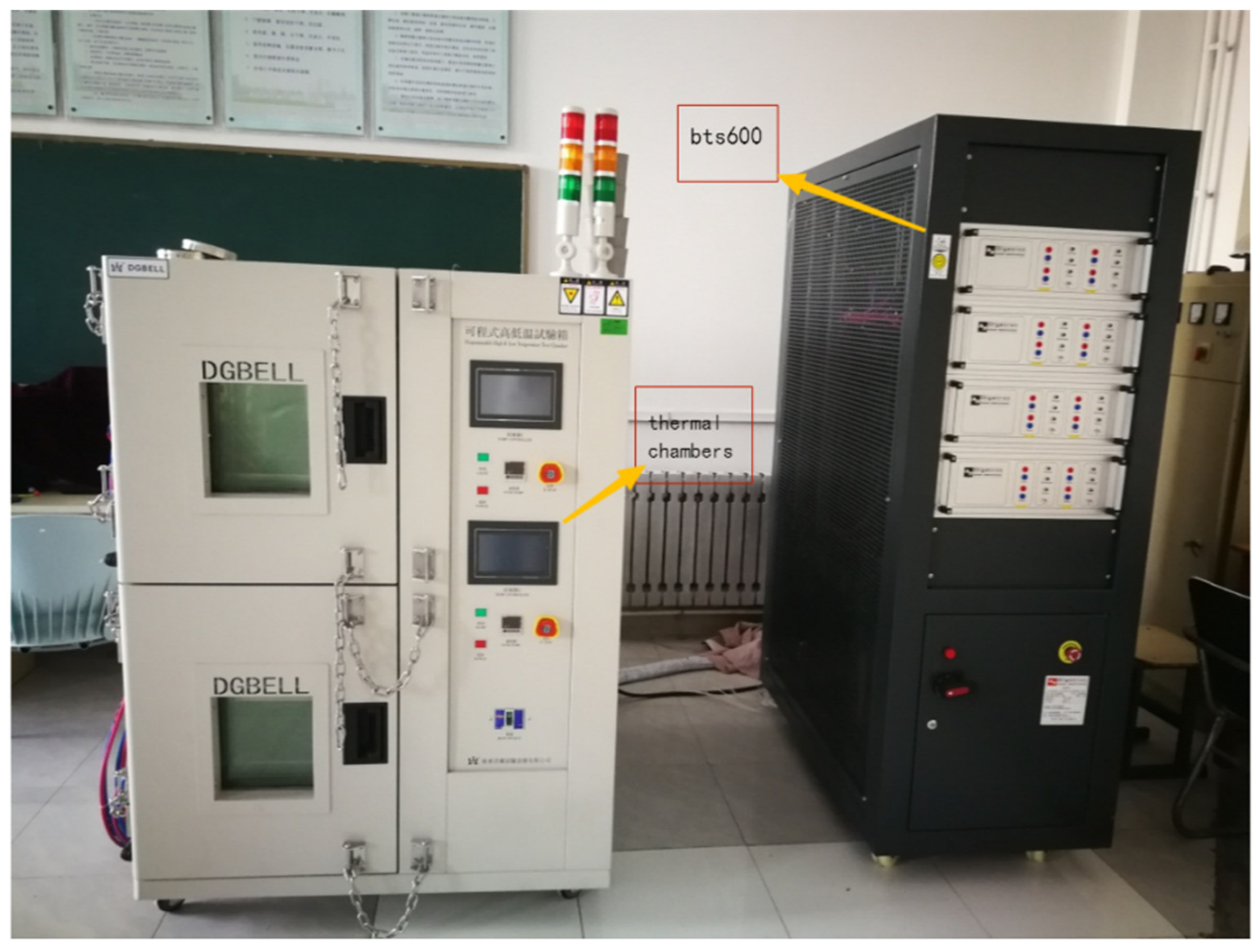
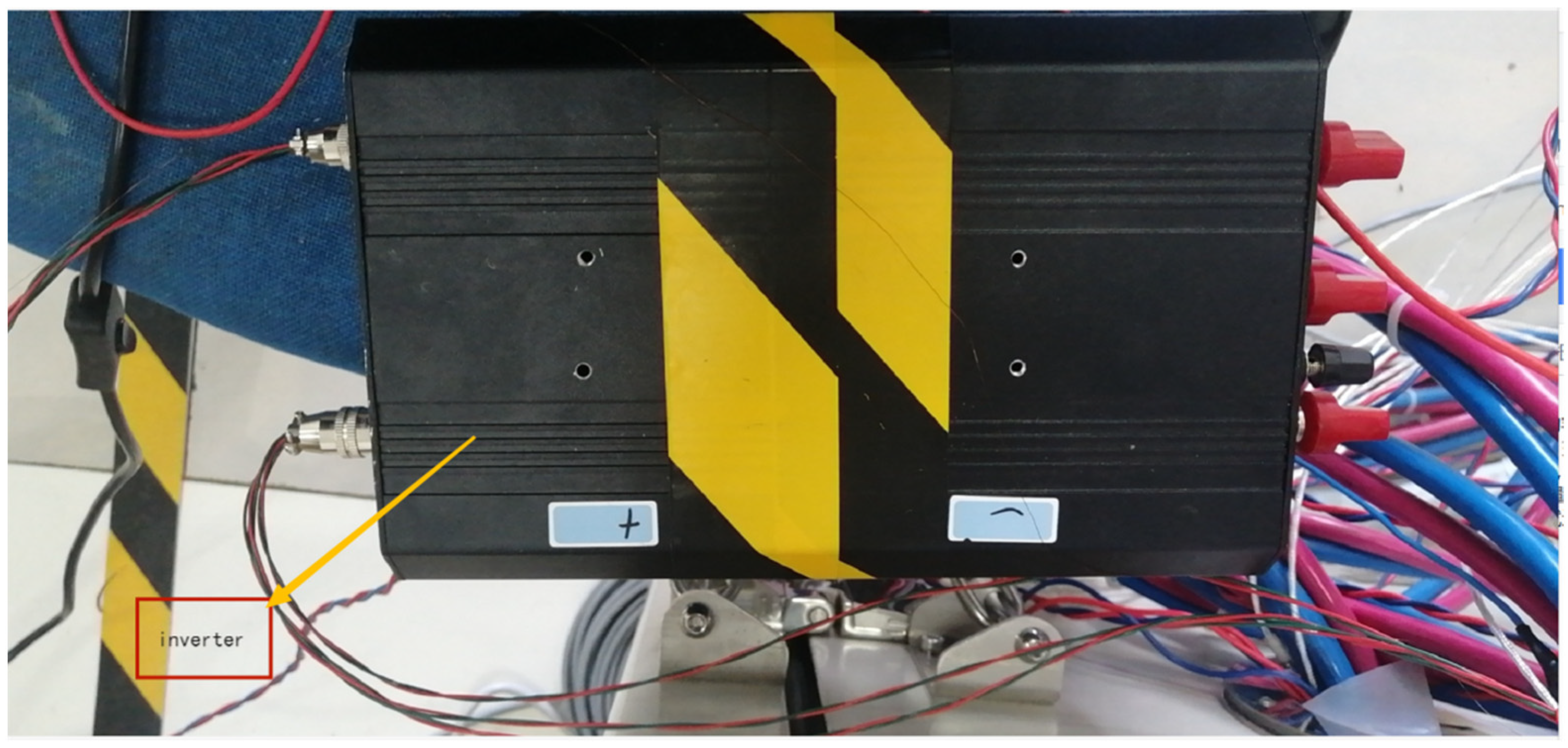
3.1. Experiment Setup
3.2. Test Scheme
4. Results and Discussion
4.1. The Influence of Temperature on the Charging Speed
4.2. Effects of Initial SOC on Charging Speed
5. Conclusions
Author Contributions
Funding
Institutional Review Board Statement
Informed Consent Statement
Conflicts of Interest
References
- Bresser, D.; Hosoi, K.; Howell, D.; Li, H.; Zeisel, H.; Amine, K.; Passerini, S. Perspectives of automotive battery R&D in China, Germany, Japan, and the USA. J. Power Sources 2018, 382, 176–178. [Google Scholar]
- Esfandyari, M.; Esfahanian, V.; Yazdi, M.H.; Nehzati, H.; Shekoofa, O. A new approach to consider the influence of aging state on Lithium-ion battery state of power estimation for hybrid electric vehicle. Energy 2019, 176, 505–520. [Google Scholar] [CrossRef]
- Li, S.; He, H.; Zhao, P. Energy management for hybrid energy storage system in electric vehicle: A cyber-physical system perspective. Energy 2021, 230, 120890. [Google Scholar] [CrossRef]
- Xiong, R.; Pan, Y.; Shen, W.; Li, H.; Sun, F. Lithium-ion battery aging mechanisms and diagnosis method for automotive appli-cations: Recent advances and perspectives. Renew Sustain. Energy Rev. 2020, 131, 110048. [Google Scholar] [CrossRef]
- Yang, R.; Xiong, R.; Shen, W.; Lin, X. Extreme Learning Machine Based Thermal Model for Lithi-um-ion Batteries of Electric Vehicles under External Short Circuit. Engineering 2020, 7, 395–405. [Google Scholar] [CrossRef]
- Xiong, R.; Sun, W.; Yu, Q.; Sun, F. Research progress, challenges and prospects of fault diagnosis on battery system of electric vehicles. Appl. Energy 2020, 279, 115855. [Google Scholar] [CrossRef]
- Ji, Y.; Zhang, Y.; Wang, C.-Y. Li-Ion Cell Operation at Low Temperatures. J. Electrochem. Soc. 2013, 160, A636–A649. [Google Scholar] [CrossRef]
- Li, J.; Yuan, C.F.; Guo, Z.H.; Zhang, Z.A.; Lai, Y.Q.; Liu, J. Limiting factors for low-temperature performance of electrolytes in LiFePO 4/Li and graphite/Li half cells. Electrochim. Acta 2012, 59, 69–74. [Google Scholar] [CrossRef]
- Abraham, D.P.; Heaton, J.R.; Kang, S.-H.; Dees, D.W.; Jansen, A.N. Investigating the Low-Temperature Impedance Increase of Lithium-Ion Cells. J. Electrochem. Soc. 2008, 155, A41–A47. [Google Scholar] [CrossRef]
- Zhang, S.; Xu, K.; Jow, T. A new approach toward improved low temperature performance of Li-ion battery. Electrochem. Commun. 2002, 4, 928–932. [Google Scholar] [CrossRef]
- Zhang, S.; Xu, K.; Jow, T. An inorganic composite membrane as the separator of Li-ion batteries. J. Power Sources 2005, 140, 361–364. [Google Scholar] [CrossRef]
- Zhang, S.; Xu, K.; Jow, T. Low temperature performance of graphite electrode in Li-ion cells. Electrochim. Acta 2002, 48, 241–246. [Google Scholar] [CrossRef]
- Qiao, Y.; Tu, J.; Wang, X.; Gu, C. The low and high temperature electrochemical performances of Li3V2(PO4)3/C cathode ma-terial for Li-ion batteries. J. Power Sources 2012, 199, 287–292. [Google Scholar] [CrossRef]
- Zhang, S.; Xu, K.; Jow, T. Electrochemical impedance study on the low temperature of Li-ion batteries. Electrochim. Acta 2004, 49, 1057–1061. [Google Scholar] [CrossRef]
- Zhang, S.; Xu, K.; Jow, T. The low temperature performance of Li-ion batteries. J. Power Sources 2003, 115, 137–140. [Google Scholar] [CrossRef]
- Fan, J.; Tan, S. Studies on Charging Lithium-Ion Cells at Low Temperatures. J. Electrochem. Soc. 2006, 153, A1081–A1092. [Google Scholar] [CrossRef]
- Bitzer, B.; Gruhle, A. A new method for detecting lithium plating by measuring the cell thickness. J. Power Sources 2014, 262, 297–302. [Google Scholar] [CrossRef]
- Legrand, N.; Knosp, B.; Desprez, P.; Lapicque, F.; Raël, S. Physical characterization of the charging process of a Li-ion battery and predic-tion of Li plating by electrochemical modelling. J. Power Sources 2014, 245, 208–216. [Google Scholar] [CrossRef]
- Uhlmann, C.; Illig, J.; Ender, M.; Schuster, R.; Ivers-Tiffée, E. In situ detection of lithium metal plating on graphite in experimental cells. J. Power Sources 2015, 279, 428–438. [Google Scholar] [CrossRef]
- Zinth, V.; Von Lüders, C.; Hofmann, M.; Hattendorff, J.; Buchberger, I.; Erhard, S.; Rebelo-Kornmeier, J.; Jossen, A.; Gilles, R. Lithium plating in lithium-ion batteries at sub-ambient temperatures investigated by in situ neutron diffraction. J. Power Sources 2014, 271, 152–159. [Google Scholar] [CrossRef]
- Cho, H.M.; Choi, W.S.; Go, J.Y.; Bae, S.; Shin, H. A study on time-dependent low temperature power performance of a lithium-ion battery. J. Power Sources 2012, 198, 273–280. [Google Scholar] [CrossRef]
- Zhang, S.; Xu, K.; Jow, T. Charge and discharge characteristics of a commercial LiCoO2-based 18650 Li-ion battery. J. Power Sources 2006, 160, 1403–1409. [Google Scholar] [CrossRef]
- Fan, J. On the discharge capability and its limiting factors of commercial 18650 Li-ion cell at low temperatures. J. Power Sources 2003, 117, 170–178. [Google Scholar] [CrossRef]
- Zhao, H.; Duan, Y.L.; Ge, G.L.; Chen, Y.G. Study on performance of low temperature type lithium ion battery. Chin. J. Power Sources 2009, 1, 019. [Google Scholar]
- Harris, V.; Miller, R.L. Vehicle Heating and Cooling System. U.S. Patent 4,280,330, 28 July 1981. [Google Scholar]
- Song, H.S.; Jeong, J.B.; Leenb, H.; Shin, D.; Kim, B.; Kim, T.; Heo, H. Experimental study on the effects of pre-heating a battery in a low-temperature environment. In Proceedings of the 2012 IEEE Vehicle Power and Propulsion Conference, Seoul, Korea, 9–12 October 2012; pp. 1198–1201. [Google Scholar]
- Furman, G.R. Automotive Battery Heating System. U.S. Patent 2,440,369, 7 April 1948. [Google Scholar]
- Malecek, E.L. Battery Heating Device and Method. U.S. Patent 5,731,568, 24 March 1998. [Google Scholar]
- Godard, P.; Prevot, C. Method and Device for Charging and Heating at Low Temperature a Sealed Storage Cell Battery. U.S. Patent 4,025,861, 24 May 1977. [Google Scholar]
- Kamenoff, R. Self-Heating Battery That Automatically Adjusts Its Heat Setting. U.S. Patent 11,178,985, 19 January 2006. [Google Scholar]
- Wilmer, K. Battery Heater. U.S. Patent 2,611,853, 23 September 1952. [Google Scholar]
- Mccall, D.J. Battery Warmer with Timer Switch. U.S. Patent 5,994,669, 30 November 1999. [Google Scholar]
- Tian, J.; Xiong, R.; Shen, W.; Lu, J. State-of-charge estimation of LiFePO4 batteries in electric vehicles: A deep-learning enabled approach. Appl. Energy 2021, 291, 116812. [Google Scholar] [CrossRef]
- Ashtiani, C.N. Heating of Batteries Using Reactive Power. U.S. Patent 7,382,102, 3 June 2008. [Google Scholar]
- Ashtiani, C.N.; Stuart, T.A. Battery Self-Warming Mechanism Using the Inverter and the Battery Main Disconnect Circuitry. U.S. Patent 6,882,061, 19 April 2005. [Google Scholar]
- Ashtiani, C.N.; Stuart, T.A. Efficient Resonant Self-Heating Battery Electric Circuit. U.S. Patent 6,072,301, 6 June 2000. [Google Scholar]
- Carkner, S. Self Heating Battery System. U.S. Patent 9,083,065, 14 July 2015. [Google Scholar]
- Hande, A. Internal battery temperature estimation using series battery resistance measurements during cold tempera-tures. J. Power Sources 2006, 158, 1039–1046. [Google Scholar] [CrossRef]
- Hande, A. A high frequency inverter for cold temperature battery heating. In Proceedings of the 2004 IEEE Workshop on Computers in Power Electronics, Urbana, IL, US, 15–18 August 2004; pp. 215–222. [Google Scholar]
- Hande, A.; Stuart, T. AC heating for EV/HEV batteries. In Proceedings of the Power Electronics in Transportation, Auburn Hills, MI, USA, 24–25 October 2002; pp. 119–124. [Google Scholar]
- Vanderslice, W.T., Jr.; Scafidi, C.J. Battery Heating System Using Internal Battery Resistance. U.S. Patent 5,362,942, 8 November 1994. [Google Scholar]
- Wu, X.; Chen, Z.; Wang, Z. Analysis of Low Temperature Preheating Effect Based on Battery Temperature-Rise Model. Energies 2017, 10, 1121. [Google Scholar] [CrossRef] [Green Version]
- Ji, Y.; Wang, C.Y. Heating strategies for Li-ion batteries operated from subzero temperatures. Electrochim. Acta 2013, 107, 664–674. [Google Scholar] [CrossRef]
- Wang, C.Y.; Zhang, G.; Ge, S.; Xu, T.; Ji, Y.; Leng, X.; Yang, Y. Lithium-ion battery structure that self-heats at low temperatures. Nature 2016, 529, 515. [Google Scholar] [CrossRef]
- Vernardou, D.; Kazas, A.; Apostolopoulou, M.; Katsarakis, N.; Koudoumas, E. Hydrothermal Growth of MnO2 at 95 °C as an Anode Material. Int. J. Thin Film Sci. Technol. 2016, 5, 121–127. [Google Scholar] [CrossRef]
- Al-Qrinawi, M.S.; El-Agez, T.M.; Abdel-Latif, M.S.; Taya, S.A. Capacitance-voltage measurements of hetero-layer OLEDs treated by an electric field and thermal annealing. Int. J. Thin Film Sci. Technol. 2021, 10, 217–226. [Google Scholar]
- Elhadary, A.A.; El-Zein, A.; Talaat, M.; El-Aragi, G.; El-Amawy, A. Studying the Effect of the Dielectric Barrier Discharge Non-thermal Plasma on Colon Cancer Cell line. Int. J. Thin Film Sci. Technol. 2021, 10, 161–168. [Google Scholar]
- Joshi, V.; Kapoor, M. A Novel Technique for Numerical Approximation of 2 Dimensional Non-Linear Coupled Burgers’ Equations Using Uniform Algebraic Hyperbolic (UAH) Tension B-Spline Based Differential Quadrature Method. Appl. Math. Inf. Sci. 2021, 15, 217–239. [Google Scholar]
- Von Lüders, C.; Zinth, V.; Erhard, S.V.; Osswald, P.J.; Hofmann, M.; Gilles, R.; Jossen, A. Lithium plating in lithium-ion batteries inves-tigated by voltage relaxation and in situ neutron diffraction. J. Power Sources 2017, 342, 17–23. [Google Scholar] [CrossRef]
- Wang, S.; Chen, Y.; Huang, J.; Chen, N.; Lu, Y. Macrolevel Traffic Crash Analysis: A Spatial Econometric Model Approach. Math. Probl. Eng. 2019, 2019, 5306247. [Google Scholar] [CrossRef] [Green Version]


| Brand Model | LG INR18650HG2 |
|---|---|
| Standard capacity | 3000 mAh |
| Rated voltage | 3.6 V |
| Charging voltage | 4.2 ± 0.05 V |
| Battery charging | Standard 1500 mA; cutoff current 50 mA(cc-cv) |
| Fast charge | 4000 mA, cutoff current 100 mA(cc-cv) |
| Maximum continuous discharge current | 20 A |
| Discharge cut-off voltage | 2.5 V |
| Essential resistance (AC 1 KHz) | ≤20 mΩ, with our PTC |
| Charging Time | Temperature Variation | |
|---|---|---|
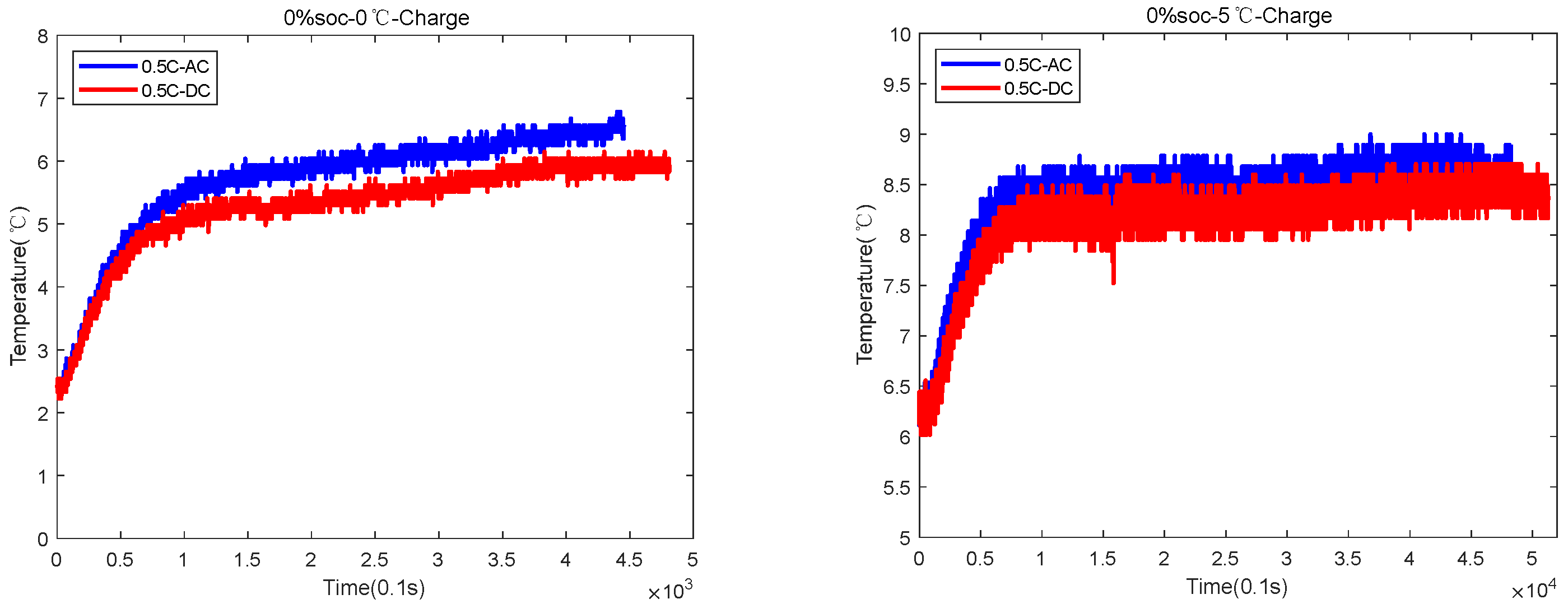
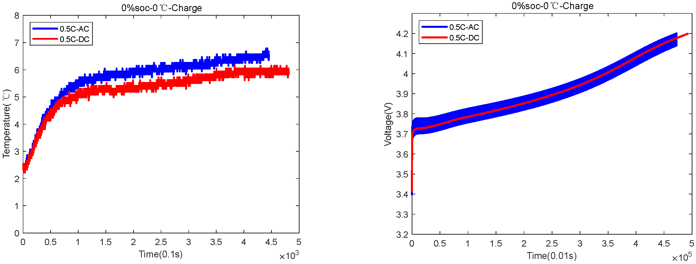
| 0%SOC-0 °C | 4300 s AC and 4800 s DC | AC temperature rose by 5 °C, and DC temperature rose by 3.5 °C |
| 0%SOC-5 °C | 4700 s for AC and 5200 s for DC | AC temperature rose by 3 °C, and DC temperature rose by 2.5 °C |
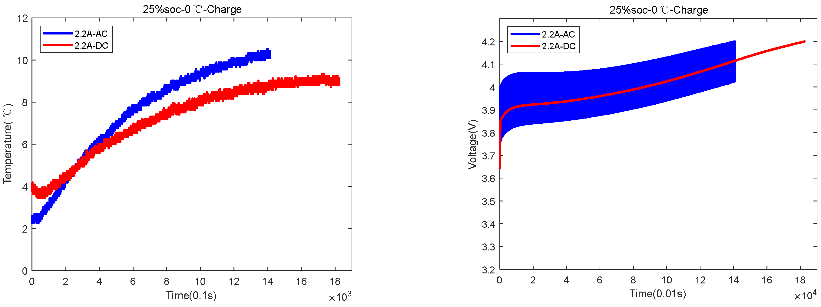
| 25%SOC-0 °C | 1300 s for AC and 1800 s for DC | AC temperature rose by 8.5 °C, and DC temperature rose by 5 °C |
| 25%SOC-5 °C | 2700 s for AC and 3800 s for DC | AC temperature rose by 3.5 °C, and DC temperature rose by 3 °C |
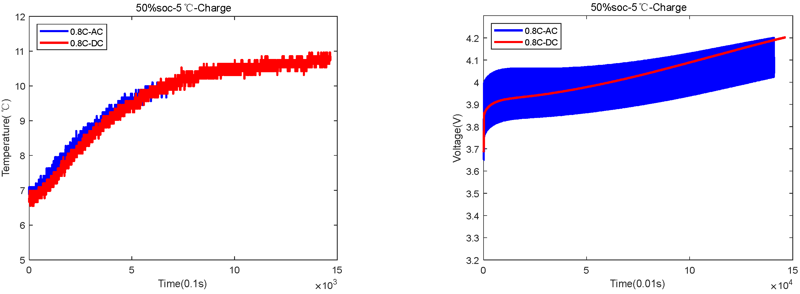
| 50%SOC-5 °C | 1400 s for AC and 1500 s for DC | AC temperature rose by 6 °C, and DC temperature rose by 4.5 °C |
Publisher’s Note: MDPI stays neutral with regard to jurisdictional claims in published maps and institutional affiliations. |
© 2022 by the authors. Licensee MDPI, Basel, Switzerland. This article is an open access article distributed under the terms and conditions of the Creative Commons Attribution (CC BY) license (https://creativecommons.org/licenses/by/4.0/).
Share and Cite
Guo, S.; Han, Z.; Wei, J.; Guo, S.; Ma, L. A Novel DC-AC Fast Charging Technology for Lithium-Ion Power Battery at Low-Temperatures. Sustainability 2022, 14, 6544. https://doi.org/10.3390/su14116544
Guo S, Han Z, Wei J, Guo S, Ma L. A Novel DC-AC Fast Charging Technology for Lithium-Ion Power Battery at Low-Temperatures. Sustainability. 2022; 14(11):6544. https://doi.org/10.3390/su14116544
Chicago/Turabian StyleGuo, Shanshan, Zhiqiang Han, Jun Wei, Shenggang Guo, and Liang Ma. 2022. "A Novel DC-AC Fast Charging Technology for Lithium-Ion Power Battery at Low-Temperatures" Sustainability 14, no. 11: 6544. https://doi.org/10.3390/su14116544