Article

Coordinated Design of Type-2 Fuzzy Lead–Lag-Structured SSSCs and PSSs for Power System Stability Improvement

by
Prabodh Khampariya
1,
Sidhartha Panda
2,
Hisham Alharbi
3,
Almoataz Y. Abdelaziz
4,* and
Sherif S. M. Ghoneim
3,*
1
Department of EEE, Sri Satya Sai University of Technology & Medical Sciences, Sehore 466001, India
2
Department of Electrical Engineering, Veer Surendra Sai University of Technology, Odisha 768018, India
3
Electrical Engineering Department, College of Engineering, Taif University, P.O. Box 11099, Taif 21944, Saudi Arabia
4
Faculty of Engineering and Technology, Future University in Egypt, Cairo 11835, Egypt
*
Authors to whom correspondence should be addressed.
Sustainability 2022, 14(11), 6656; https://doi.org/10.3390/su14116656
Submission received: 18 April 2022 / Revised: 20 May 2022 / Accepted: 26 May 2022 / Published: 29 May 2022

Abstract

:
This work suggests a type-2 fuzzy lead–lag (T2FLL) controller structure for flexible AC transmission system (FACTS)-based damping controllers and power system stabilizers (PSSs) for power system stability improvement. The values of the suggested controller are optimized by a hybrid adaptive differential evolution and pattern search algorithm (hADE-PS) method. Initially, a single-machine infinite-bus (SMIB) system with lead–lag (LL)-structured FACTS and PSS controllers is considered, and the dominance of the hADE-PS method is established over the original differential evolution (DE), genetic algorithm (GA), and particle swarm optimization (PSO). The supremacy of T2FLL over the lead–lag (LL) controller is established under different large and small disturbance conditions, as well as varied loading conditions and fault positions. Lastly, the effectiveness of T2FLL is evaluated in a multimachine power system (MMPS). It is demonstrated that the suggested T2FLL offers better performance than the LL controller under various large and small disturbance conditions by providing significantly more damping to all modes of oscillations.

1. Introduction

Low-frequency oscillations are detected after disturbances in power systems that are joined by weak transmission lines. Under such circumstances, a lack of adequate system damping may result in sustained oscillations and, in turn, lead to the separation of the system [1,2]. To handle this issue, power system stabilizers (PSSs) are extensively favored by utilities. However, PSSs may not provide sufficient damping, and additional controllers are required. In this regard, recently developed flexible AC transmission system (FACTS) devices can be employed to provide the required damping. The static synchronous series compensator (SSSC) is an effective series FACTS device for power flow control and, hence, can be designed to provide additional damping [3].
Various soft-computing-based schemes have been suggested for damping controller design. Methodologies such as particle swarm optimization (PSO) [4,5], genetic algorithm (GA) [6,7], oppositional cuckoo algorithm [8], simulated annealing (SA) [9], tabu search (TS) [10], and bacteria foraging algorithm (BFA) [11] have been proposed in the literature. When SSSCs and PSSs are present in a power system, both should be coordinately designed. In the literature, PSSs are coordinately designed with other controllers such as PSS and SSSC by GA [12], PSS and SVC by GA [13], PSS and SSSC by hybrid PSO and gravitational search algorithm (GSA) [14], and PSS and thyristor-controlled series compensator (TCSC) [15,16,17]. It is observed in the literature that lead–lag (LL) controllers are commonly employed by researchers as structures of damping controllers. Recently, fuzzy logic controllers (FLCs) have been proposed by researchers, as FLCs can operate with imprecise inputs and handle nonlinearity. In [18], an improved control strategy has been proposed using a fuzzy PID regulator for a hybrid system. An FLC-based hybrid scheme is projected in [19] for power oscillation damping with FACTS and PSS controllers. In [20], a mixture of fuzzy-neural schemes is employed to capture maximum power. A hybrid firefly swarm-based type-2-based fractional-order (FO) fuzzy PID-structured PSS has been suggested in [21] for stability improvement of power systems.
Different optimization techniques such as the cuckoo search (CS) algorithm [22] and BAT search algorithm [23] have been employed in the literature for the optimal design of PSS parameters, and the superiority of the approach for system damping was demonstrated for various loading conditions. Numerous optimization-technique-based FACTS devices such as CS-based static synchronous compensator (STATCOM) [24], flower-pollination-based FACTS damping controller for a multimachine power system (MMPS) [25], and gravitational search algorithm (GSA)-based SSSCs [26] have been proposed for power system stability improvement. It is also demonstrated in the literature that when PSS and FACTS devices are present, they should be designed in a coordinated manner for achieving improved system performance [27].
From the above survey, it is evident that many optimization methods have been used for various power system problems, but no technique is exactly suited for all types of problems, and there are opportunities for performance enhancement by proposing new and modified techniques. Differential evolution (DE) is an easy but capable optimization method [28]. DE effectiveness relies on the choice of DE parameters such as crossover constant (Cr) and scaling factor (F) [28]. Throughout the search procedure, appropriate F and Cr parameters must be engaged in place of employing constant parameters during the evolution. An adaptive method is suggested here, where an adaptive mechanism is used for the selection of suitable F and Cr parameters during the optimization procedure. As DE is a global search method, it is intended for exploring the search area. To improve search capabilities, hybrid schemes have been recently projected for engineering design problems. A hybrid DE–PS procedure was suggested in [29] to tune the modified integral-derivative (MID) structure for frequency regulation. Fuzzy PID values are tuned by many hybrid optimization liaisons and GSAs for different systems in [30]. A hybrid-shuffled frog-leaping and PS-tuned PID has been proposed for frequency control in [31]. Recently, a hybrid-modified DE and PS (hMDE-PS)-based SSSC controller was proposed under communication constraints for stability improvement [32]. The superiority of hMDE-PS over other variants of DE such as JADE [33], CoDE [34], and SHADE [35] has been demonstrated for benchmark test functions. A hybrid adaptive DE and PS (hADE-PS)-based fractional-order fuzzy PID (FOFPID) structure for frequency regulation of power systems was reported in [36], where the performance of the FOFPID controller was equated with a double-derivative PI and PID controller for assessing frequency regulation performance using transfer function models of power systems.
Based on the above facts, this work proposes a novel scheme by employing a hybrid ADE and PS (hADE-PS) method for the coordinated design of a type-2 fuzzy lead–lag (T2FLL)-structured FACTS controller and PSS for power oscillation damping. The effectiveness of hADE-PS is compared with other popular algorithms such as GA, PSO, and the original DE. The novelties of the current work are:
i.
A new controller structure, known as type-2 fuzzy lead–lag (T2FLL), is proposed in this paper for PSS- and SSSC-based controllers for power system stability improvement.
ii.
The design task is taken as an optimization problem, and controller parameters are optimized by a recently proposed hADE-PS method.
iii.
Technique-wise, the hDE-PS method is compared with GA, PSO, and DE methods, and controller-wise, T2FLL is compared with type-1 fuzzy lead–lag (T1FLL) and widely used lead–lag (LL) controllers.
iv.
Various disturbance scenarios and changed loading/fault locations are simulated for both single-machine infinite-bus (SMIB) and MMPS, and it is seen that improved damping is attained with T2FLL related to T1FLL and LL controllers for all scenarios.
This paper is structured as follows: Section 2 introduces the systems under investigation. The projected control approach is described in Section 3. An overview of the hybrid adaptive DE and PS technique is provided in Section 4. Results are discussed in Section 5. Conclusions and future work are provided in Section 6.

2. Systems under Investigation

2.1. The SMIB System

Initially, SMIB system exposed in Figure 1 is taken. In Figure 1, the transformer is represented by T; the infinite bus and generator terminal voltages are denoted by VS and VT, respectively; while V1 and V2 are the bus voltages, the SSSC converter output voltage and the DC voltage source are represented by Vcnv and VDC, respectively; the line current is I; the real powers in the transmission lines and one line are each represented by PL and PL1, respectively. The generator is provided with a turbine and governor, an excitation system, and a PSS. The excitation system contains a voltage regulator and exciter [37]. The system parameters are specified in Appendix A.

2.2. Kundur’s Test System (Four-Machine Two-Area)

The multi-machine power system (MMPS) contains 11 buses and 2 areas, joined by a weak transmission line as revealed in Figure 2. Loads and shunt capacitors are assumed at buses 7 and 9. The 2 areas are joined by 2 lines of 220 km. It was precisely planned to investigate low-frequency oscillations [38]. The test system follows the characteristics of usual systems in real operation. The load is characterized as constant impedances. The power transfer from area 1 to area 2 is 413 MW. The system is stressed and oscillates in the occurrence of any disturbance. The system details are taken from [38] and given in Appendix A.

3. The Proposed Approach

3.1. Type-2 Fuzzy Logic Overview

When uncertainties are present, the conventional fuzzy logic control (FLC) may not be effective to improve the performance of the system. However, the twin membership function (MF) grounded type-2 FLC (T2F) provides improved system performance. The present study proposes a type-2 fuzzy lead–lag (T2FLL) controller as a damping controller. The MFs of the T2FLL engage upper and lower MFs (UMF and LMF). The type-2 fuzzy act includes fuzzification, knowledge base, type reducer (TR), and defuzzification.
Fuzzification is the initial phase of FLC. It processes inputs and creates the necessary prearranged fuzzy sets by the MFs. The linguistic parameters engaged for MFs are Extreme Positive (EXP), Least Positive (LP), Zero (ZER), Least Negative (LN), and Extreme Negative (EXN.
The T2F fuzzy set (FS) is formulated as:
F S = ( ( V a r , a ) , μ U ( V a r , a ) ) , ν V a r P , ν a J V a r [ 0 , 1 ]
where μ U ( V a r , a ) is the UMF, Var is the main variable, a is the extra parameter in area JVar
The universe of discourse is formulated as:
F S = V a r P a J V a r [ 0 , 1 ] μ E ( V a r , a ) ( V a r , a )
where, = Union on ACE and a
Now the membership expression is:
μ U ( V a r , a ) = F O U ( U ) ¯ ν V a r P , ν a J V a r [ 0 , 1 ]
where JVar is expressed as:
J V a r = [ μ U ¯ ( V a r , a ) , μ U _ ( V a r , a ) ] ν V a r P , ν a J V a r [ 0 , 1 ]
The MF associated with type-I FLC inspires to develop MFs of T2F.
The rule base and interface engine form the knowledge base. The rule base is demonstrated in Table 1. Individually, Var and dAVar are the inputs to T2F and y is the output.
The characteristic of the type-2 FLC is
L M F : f o r V a r = L N _ ; d V a r = Z _ ; Y = L N _
U M F : f o r V a r = L N ¯ ; d V a r = Z ¯ ; Y = L N ¯
where L N _ , Z _ and L N ¯ , Z ¯ are related to LMF and UMF, respectively.
The related FS firing forte is
f s _ = min ( μ U S ¯ ( V a r , a ) , μ U S ¯ ( d V a r , a ) )
f s ¯ = max ( μ U S ¯ ( V a r , a ) , μ U S ¯ ( d V a r , a ) )
F S = [ f s _ , f s ¯ ]
where f s _ and f s ¯ are related to LMF and UMF, respectively.
Type reduction (TR) is used to modify type-2 to type-1 FS for defuzzification. The schemes for defuzzification are centroid, the center of sets (SOC), and the center of sums. Here, SOC is used as it is reported as the best scheme. The outputs are:
Y cos = s = 1 25 F s Y s F s = [ Y m 1 , Y m 2 ]
Y m 1 = s = 1 25 f s y s _ s = 1 25 f y ¯
Y m 2 = s = 1 25 f s y s ¯ s = 1 25 f s ¯
where Y m 1 and Y m 2 are associated with MFs of type-1 FLC. The output of type-2 FLC Y cos is found by averaging. The recommended T2FLL is set bearing in mind all characteristics of lead–lag controller and T2F.

3.2. Structure of T2FLL Controller

The configuration of the proposed type-2 fuzzy lead–lag (T2FLL) SSSC-based controller is revealed in Figure 3. It contains a sensor block, transport delay block, scaling factor blocks for fuzzy input, gain, a washout, and lead–lag (LL) blocks. The washout tie constant is generally taken as 10 s [38]. The LL blocks deliver the suitable phase lead to balance for the lag among output and input. The output of the controller is the Vq.
Figure 4 shows the structure of the T2FLL-based PSS. It consists of a gain, washout, and LL block. The speed variation is fed as input to the PSS. The PSS output (Vs) is used to change the excitation voltage.
Speed deviations are selected as T2FLL controller input signals. A sensor time constant of 15 ms is assumed. A transport delay of 50 ms is assumed for the SSSC controller.

3.3. Optimization Problem

An integral time multiplied absolute error (ITAE) criterion is employed for the SMIB system. For MMPS, an ITAE criterion using local and inter-area modes of oscillations is selected. They are represented by:
For SMIB:
J = t = 0 t = t s i m | Δ ω | t d t
For MMPS:
J = t = 0 t = t s i m ( | Δ ω L | + | Δ ω I | ) t d t
where Δω is the speed deviance in the SMIB system, ΔωL and ΔωI are the speed deviations of MMPS related to local and inter-area modes, respectively, and tsim is the simulation time.
Therefore, the design task is formulated as an optimization task as:
Minimize J
Subject to
KSFi min KSFi KSFi max ( KSFi = Scaling factors ) Ki min Ki Ki max ( Ki = Gains ) Ti min Ti Ti max ( Ti = Time constants )
The limits of the parameters are [0.01–100] for Ki, [0.01–10] for Ti, and [0.01–100] for KFSi. In the present work, the hADE-PS algorithm determines T2FLLvalues.

4. Overview of Hybrid Adaptive DE and PS Technique

The differential evolution (DE) method is a simple, competent but efficient method [28]. Encouraged by the evolution approach, the DE method is found to be a capable method for complex engineering problems. The stages of DE are:

4.1. Mutation

The mutant vector w j | i is to be performed for each parent vector y j | i on each generation ‘i’ is:
w j | i = y q 1 | i + F ( y q 2 | i y q 3 | i )
where q 1 q 2 q 3 j . F indicates the scaling factor.

4.2. Crossover

It is a vital method for the expansion of population diversity. In Binary crossover, the trial vector v j | i = [ v 1 j | i , v 2 j | i , , v n j | i ] can be generated through the target vector y j | i and its mutant vector w j | i . As:
v l j | i = { w l j | i i f r a n d   ( 0 , 1 ) C r y l j | i o t h e r w i s e
where l 1 , 2 , , n . For every vector y j | i and w j | i , the trial vector v j | i can be generated as:
v j | i = y j | i + F j ( w j | i y j | i )

4.3. Selection

The selection operation is engaged to maintain a fixed population size in all generations. The vector having the best fitness value replaces the fewer fit vectors.
The equation representing this process is:
y j | i + 1 = { v j | i i f f ( v j | i ) f ( y j | i ) y j | i o t h e r w i s e
DE is a competent method but relies on its algorithm parameters such as F and Cr. Appropriate choice of F and Cr is vital for the performance of DE. Numerous researchers have recommended different schemes to choose F and Cr values [39].
Liu and Lampinen [40] indicated the control parameters value to evaluate the robustness as well as the effectiveness of the DE algorithm. Gamperle et al. [41] have suggested the values such as 0.6 and [0.3, 0.9] for F and Cr to control the parameters. On the other hand, Ali and Torn [42] have tested their results on the values such as 0.5 and [0.4, 1] for F and Cr. Moreover, different self-adaptive approaches are proposed to select ‘Cr &F’ during the experimentation for effective results [43].
Selecting correct F and Cr parameters is a problem-dependent task. The projected scheme uses an adaptive approach to select F and Cr values during the optimization process. For generation i, the triangular factors such as ΛF, and ΛCr have been used for evaluating f F ( y ) | i and f C r ( y ) | i for each child in the population. For Triangular Distribution factor of FF) and CrCr), where ˄F = [0.1, 1, 2] and ˄Cr = [0.1, 0.4, 1] are engaged in the present study.
To select Fi and Cri, mx (maximum), mn (minimum), and md (median) are engaged in a generation as indicated in Equations. (21) and (22).
F i = { F m n + r a n d V * ( F m x F m n ) / ( F m d F m n ) i f r a n d V < ( F m x F m n ) / ( F m d F m n ) F m x ( 1 r a n d V ) * ( F m x F m n ) / ( F m x F m d ) o t h e r w i s e
C r i = { C r m n + r a n d V * ( C r m x C r m n ) / ( C r m d C r m n ) i f r a n d V < ( C r m x C r m n ) / ( C r m d C r m n ) C r m x ( 1 r a n d V ) * ( C r m x C r m n ) / ( C r m x C r m d ) o t h e r w i s e
Here, r a n d V has been selected in an arbitrary distribution with a limit [0, 1].
Before performing the mutation scheme, the Fi and Cri values are set which affects the mutation, cross-over, and selection process for the newly generator vector y j | i + 1 . Due to the easy generation of adaptive values for F and Cr, it can maintain the time complexity as compared to conventional DE.
The pattern search (PS) method is shown to be useful in numerous hybrid approaches [23,25]. The information regarding the PS algorithm is available in the literature [23,25]. At first, the ADE technique is executed and PS is then executed considering the final results of ADE as the starting points. So, the benefit of hybridizing the ADE and PS algorithms is that the hybrid algorithm will have enhanced exploring and exploiting capability.

5. Outcomes

5.1. SMIB System

The SMIB system is developed in MATLAB / SIMULINK as displayed in Figure 5. In the present study, the ode23tb (stiff/TR-BDF2) solver which is a variable-step with 1 cycle of the fundamental frequency as the maximum time step is used as in the literature [4,5]. The system is developed using the Sim Power Systems (SPS) library of SIMULINK. The dynamics of all windings are specified in the rotor reference frame (q-d frame). The Hydraulic Turbine and Governor (HTG) and Excitation system are present in the subsystem represented by the “Generator Control System” (Reg_M).
The system model is constructed in the SIMULINK environment and optimization routines are specified in a separate m file. For ITAE evaluation, the model is simulated considering a severe disturbance. The J value is transferred to the optimization routine by transferring it to the workspace and used by the optimization program to minimize J value.
To validate the advantage of the hADE-PS approach, the LL controller is initially considered. For ITAE calculation, a 3-phase fault of 5 cycles is assumed at the midpoint of one transmission line. The lines are opened for 5 cycles to clear the fault. To authenticate the better performance of the hADE-PS method, the LL values are optimized by the hADE-PS, DE, PSO, and GA methods. It is worth mentioning here that, the parameters of the compared algorithm are taken from the related reference papers [44,45].
One important challenge of a hybrid global search (GS) and local search (LS) is the tradeoff between GS and LS because the cost of LS can be rather high. If LS is applied at the first stage, several solutions in the final generation may lie very close to each other at the end of LS, which makes it harder for the second stage GS method to maintain diversity in its population. This may lead the hybrid algorithm to converge to a local optimum. Therefore, the LS is performed at the second stage using the best solution provided by the GS method. This action tends to make the hybrid algorithm more computationally efficient and helps to prevent converging to a local optimum [29,31,32,36]. As the LS method is used to improve the solution quality (fine-tuning) but not to explore the search space to find independently the global optimum, more iterations (about 90%) are assigned to the GS method and fewer iterations (about 10%) are assigned to the LS method [29,30,31,32].
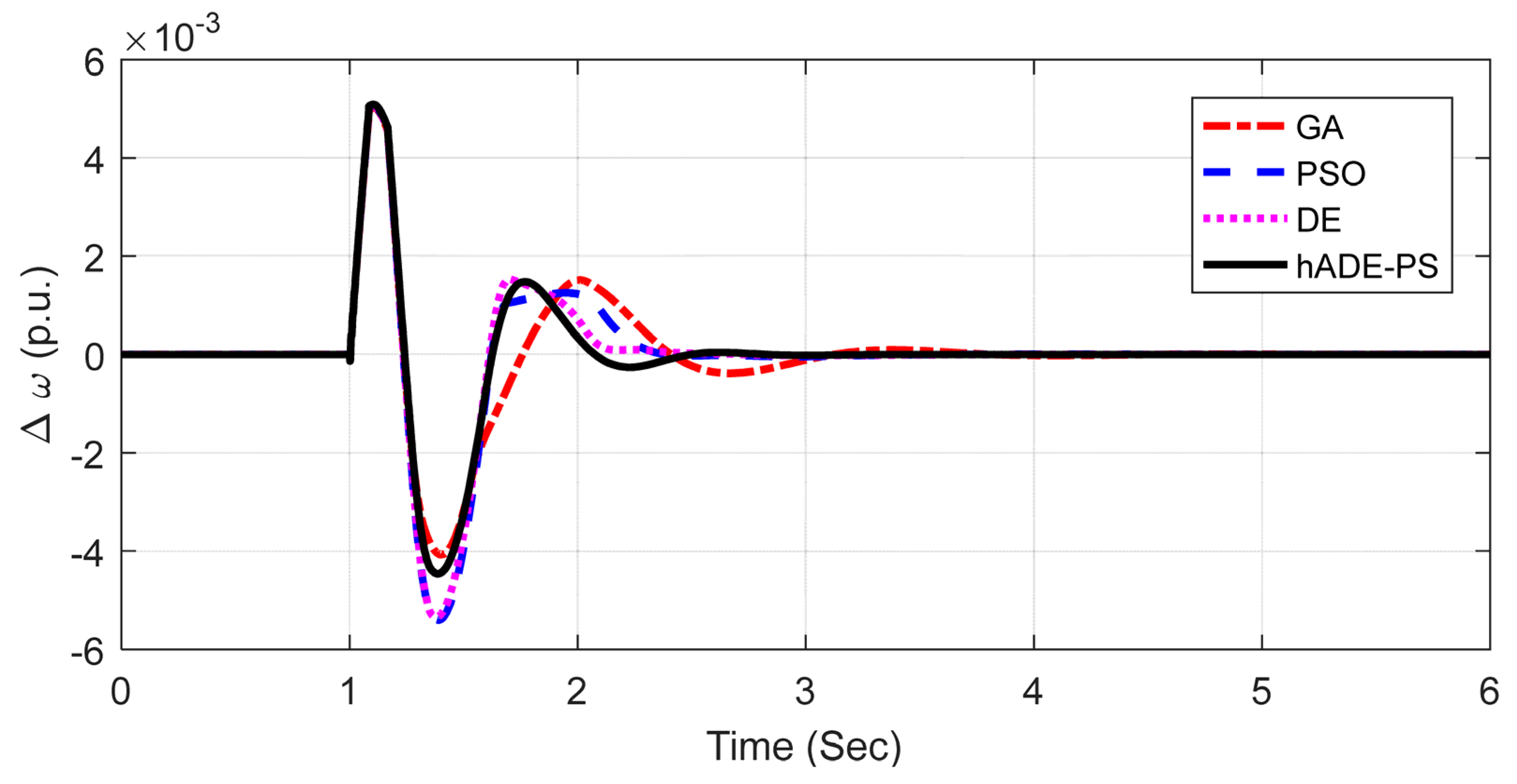
For the application of DE, PSO, and GA, 50 populations and 100 generations are employed and for the hADE-PS technique, 90 generations are assigned to the ADE technique and 10 generations are assigned to the PS technique. The parameters employed for each technique are as follows: GA: Tournament selection, Crossover and mutation rates 0.9 and 0.1; PSO: Inertia weight reduces from 0.9 to 0.2, social and cognitive components 2.0; DE: DE/best/2/bin strategy, step size and crossover probability 0.2 and 0.6. The PS is executed with a mesh size of 1, mesh expansion factor of 2 and mesh contraction factor of 0.5. The maximum number of objective function evaluations is set to 10. All the techniques are executed 10 times, and optimal values (as per the least ITAE value) obtained are taken as controller parameters. The outcomes are delivered in Table 2. It is obvious from Table 2 that, with lead–lag structure, the least ITAE values (33.7926 × 10⁻³) are obtained with the hADE-PS technique compared to GA (44.3216 × 10⁻³), PSO (40.9781 × 10⁻³) and DE (37.7718 × 10⁻³) techniques. So with the identical system and controller structure, the percentage reduction in ITAE value with hADE-PS compared to GA, PSO, and DE techniques are 23.56%, 17.53%, and 10.53%, respectively. This demonstrates the dominance of hADE-PS over GA, PSO, and DE techniques. The speed deviation response is revealed in Figure 6, from which it is evident that the best system response is attained with hADE-PS related to GA, PSO, and DE.
In the next step, the proposed Type-2 fuzzy lead–lag controller is implemented and hADE-PS-tuned parameters are specified in Table 3. For comparison, the results of the type-1 fuzzy lead–lag (T1FLL) controller are also provided in Table 3. The type-1 fuzzy part, i.e., membership functions, range, etc. is adopted from reference [36]. It can be noticed that with the same hADE-PS technique, the ITAE value is further reduced to 31.9342 × 10⁻³ with T1FLL, and the least ITAE of 28.6961 × 10⁻³ is attained with the T2FLL controller. So there is a reduction of 10.13% and 15.08% in J value with T2FLL related to the T1FLL and LL controller, respectively.
To explore the viability of T2FLL, several contingencies are taken. These scenarios are widely used in literature to evaluate the performance of and are given as follows [46,47,48].

5.1.1. Scenario 1: Large Disturbance Condition

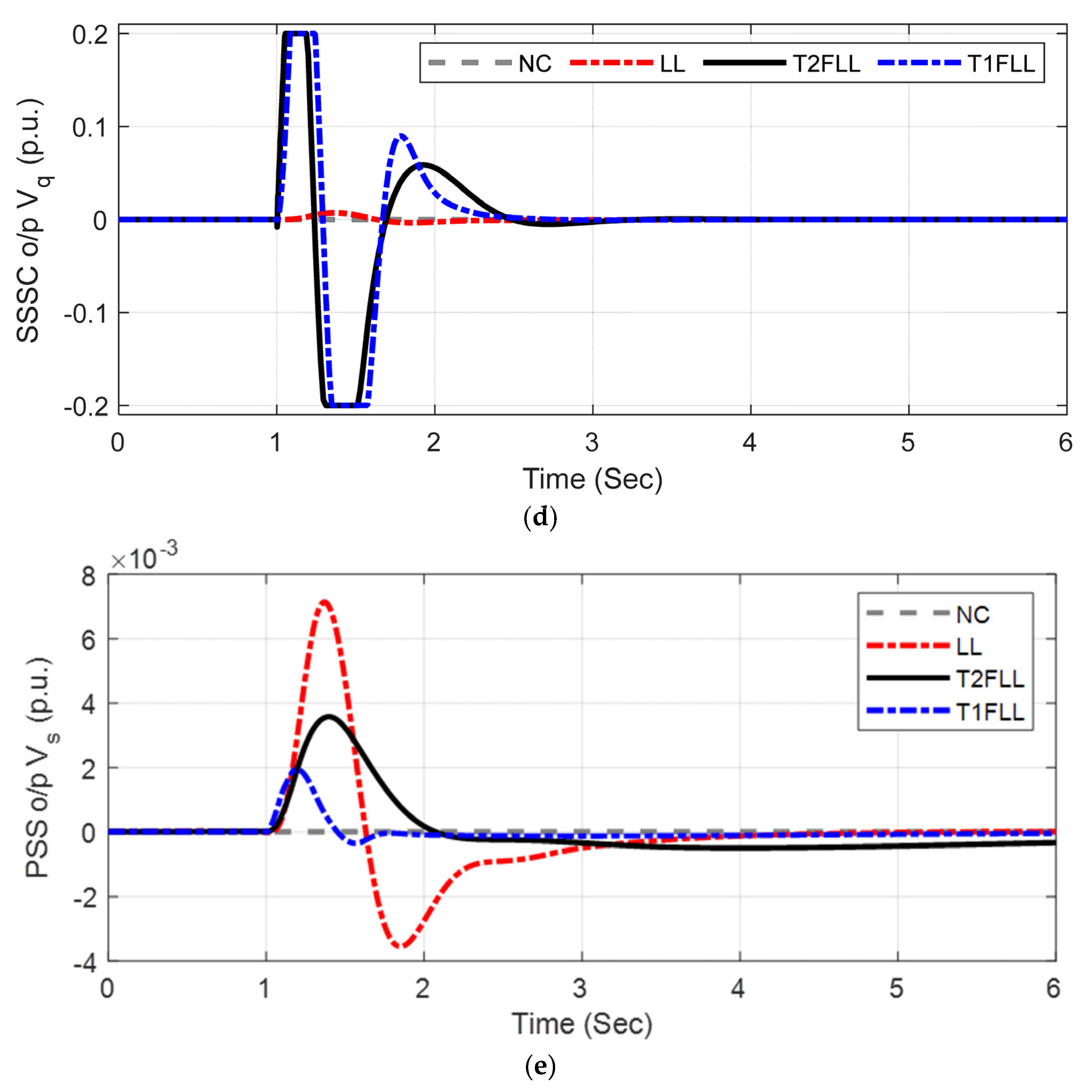
Initially, the performance is investigated at nominal loading (Pe = 0.8 p.u. δ0 = 48.5°). A 3-phase fault of 5 cycles is applied at the midpoint of one transmission line. The fault is removed by opening the line for 5 cycles. The responses with the hADE-PS-tuned LL, T1FLL, and T2FLL controllers are revealed in Figure 7a–e. For comparison, the responses without any control are also shown in Figure 7a–e. Figure 7a–e displays the speed deviation response ( Δ ω ) in p.u., power angle response (δ) in degrees, tie-line power in the line (PL) in MW SSSC output voltage (Vq) in p.u., and PSS output (Vs) in p.u. under above severe disturbance.
Figure 7a–e demonstrate that the proposed controller tuned by hADE-PS has a superior damping performance compared to both the T1FLL and LL controller. Figure 7a–c also indicate that T2FLL offers improved response with less overshoot/undershoot compared to both the T1FLL and LL controller.

5.1.2. Scenario 2: Small Disturbance Condition

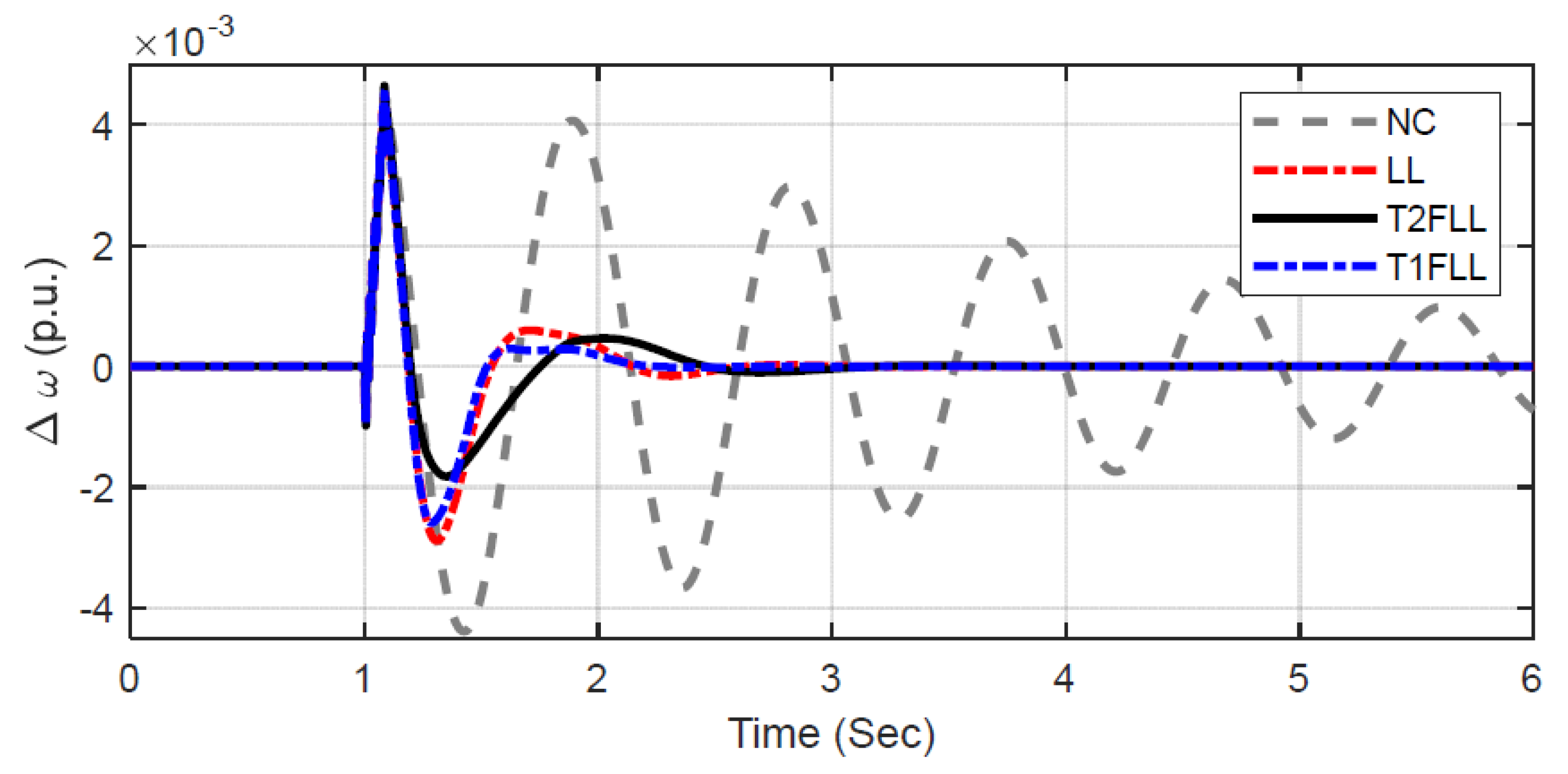
The efficiency of the T2FLL is also studied at small disturbance conditions by removing load at bus 1 for 100 ms at t = 1 s. Figure 8 displays the Δ ω response, from which it is seen that T2FLL designed at large disturbance conditions, suppresses power system oscillations efficiently at the small disturbance, and T2FLL also delivers a better transient response compared to the T1FLL and LL in this case.

5.1.3. Scenario 3: Changed Loading Condition and Fault Location

Controller efficiency is also verified in changed fault location and loading conditions. A self-clearing, 5-cycle, 3-phase fault is assumed at bus 1 in light loading (Pe = 0.5 p.u., δ0 = 38.2°) condition. Under this contingency, Δω variation is revealed in Figure 9. It is noticed that oscillations are damped quickly with T2FLL in comparison with the T1FLL and LL controllers and without the controllers.
The performance for the above three scenarios is gathered in Table 4 for improved clarification of enhancement by the proposed method. It can be observed that for different scenarios, the least performance indexes are found with T2FLL related to the T1FLL and LL controller.

5.2. Extension to Multi-Machine System (MMPS)

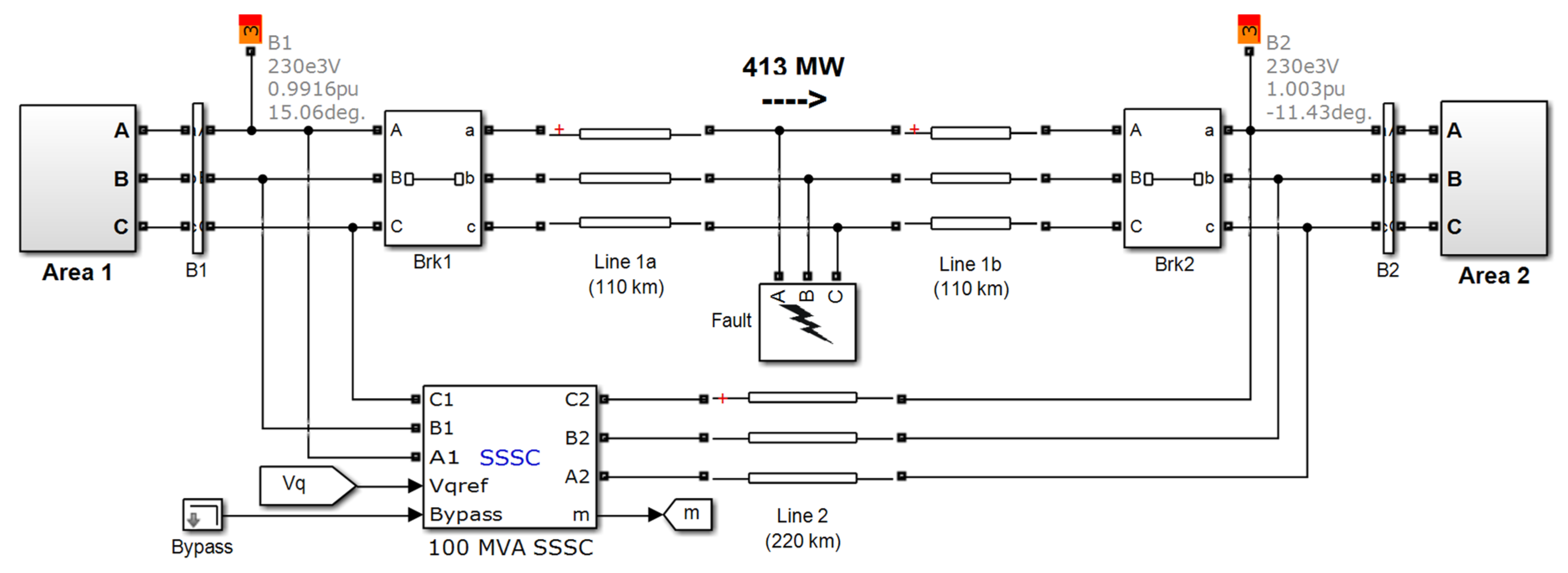
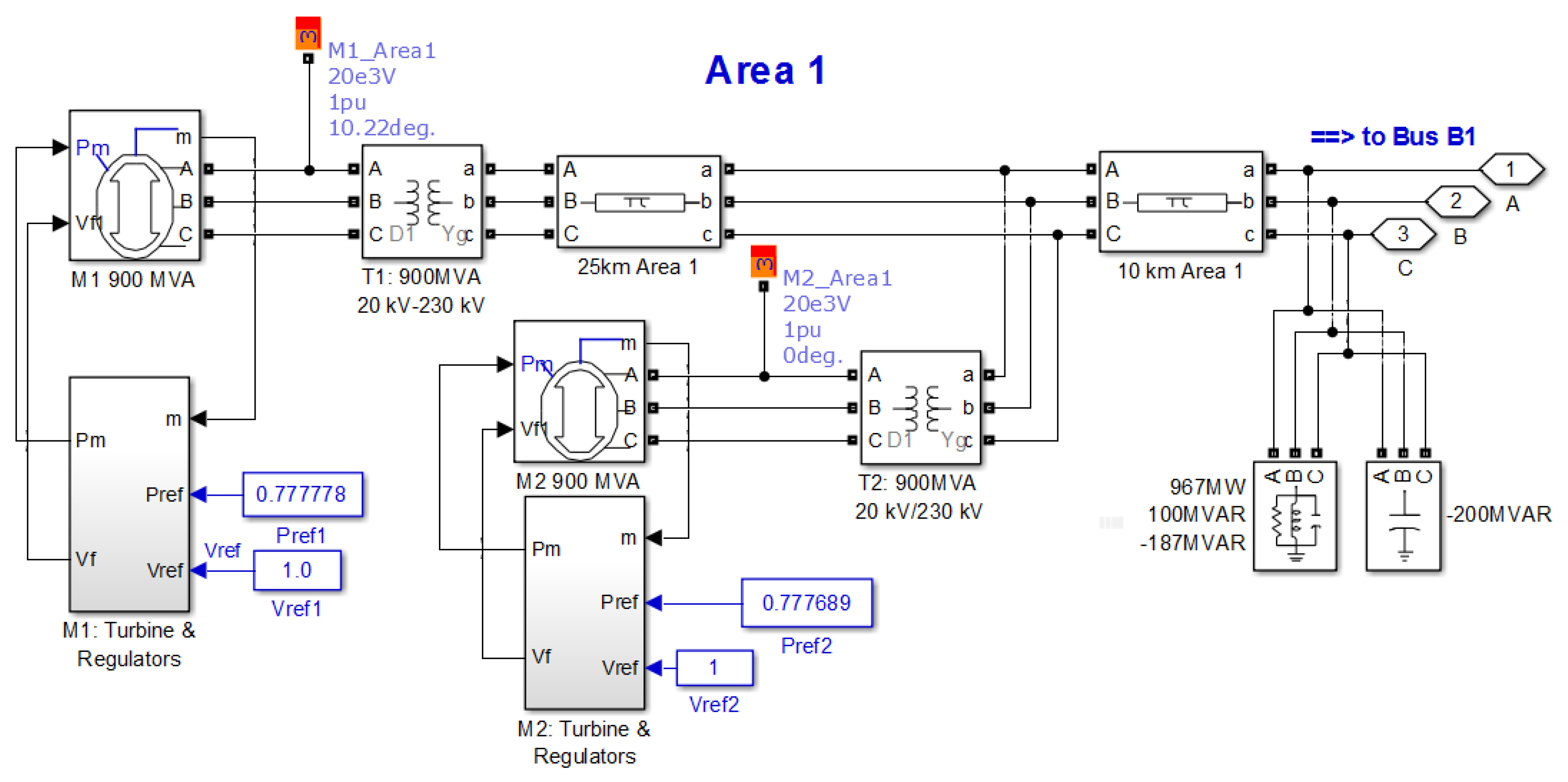
The MMPS presented in Figure 2 is taken in the next stage and constructed in the MATLAB/SIMULINK setting as revealed in Figure 10. The MATLAB/SIMULINK model of Area 1 is revealed in Figure 11. In the same way, Area 2 is also modeled. The location of series FACTS devices constitutes a major step in the employment of FACTS devices in power systems. Depending on the required objective, sensitivity analysis can be performed to decide the best location of SSSC in a large power system. Keeping in view of our objective of power system stability enhancement, the SSSC is incorporated between bus 1 and bus 2, as presented in Figure 10. To design the proposed T2FLL controller, a similar approach as used in the SMIB case is followed. The objective function is defined in Equation (14) for a multi-machine system. The tuned parameters for LL, T1FLL, and T2FLL are provided in Table 5 and Table 6, respectively.
To investigate the viability of T2FLL, several contingencies are taken. These scenarios are widely used in the literature to evaluate the performance and are given as follows [46,47,48].

5.2.1. Scenario 1: Three Phase Fault Disturbance Condition

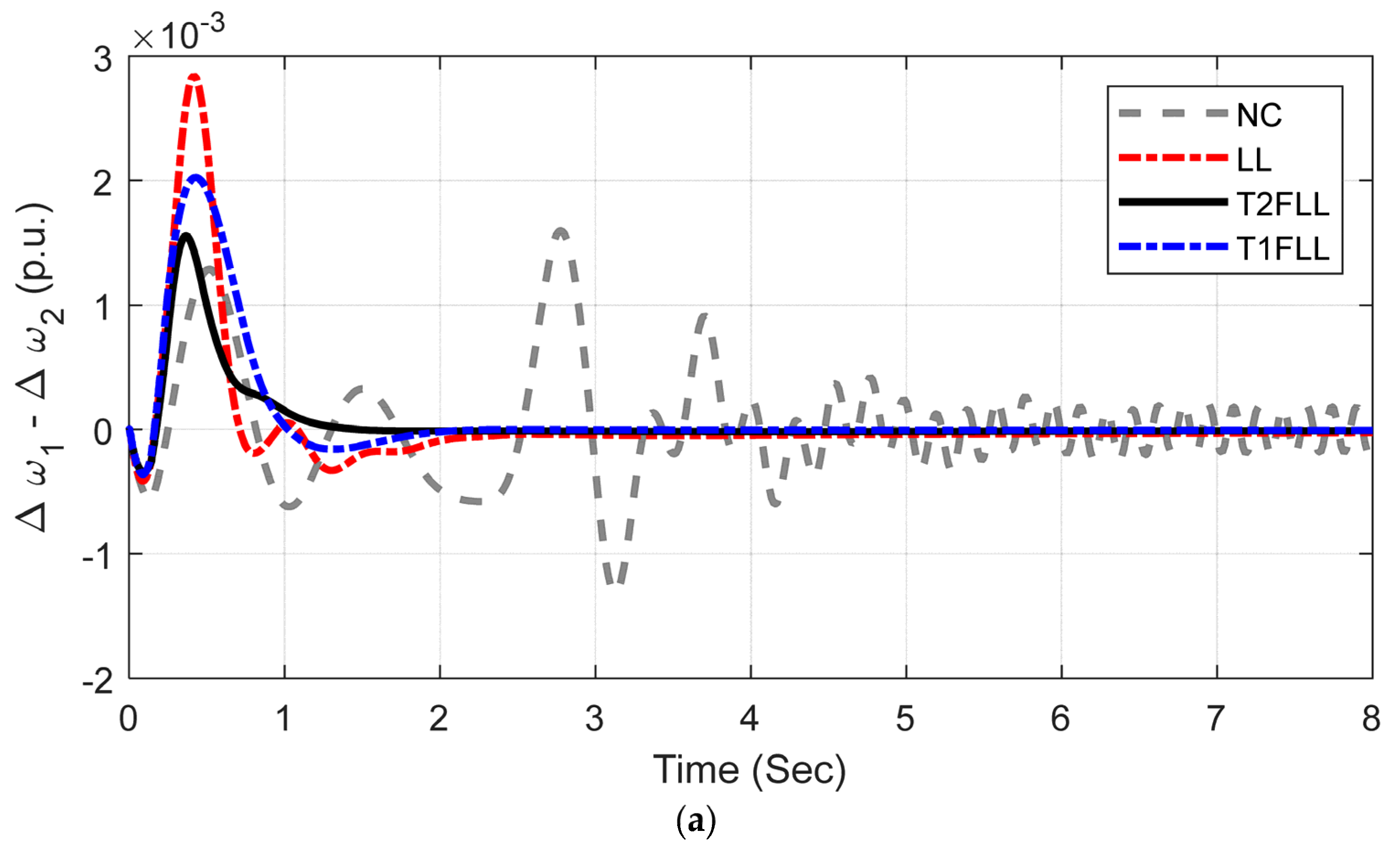
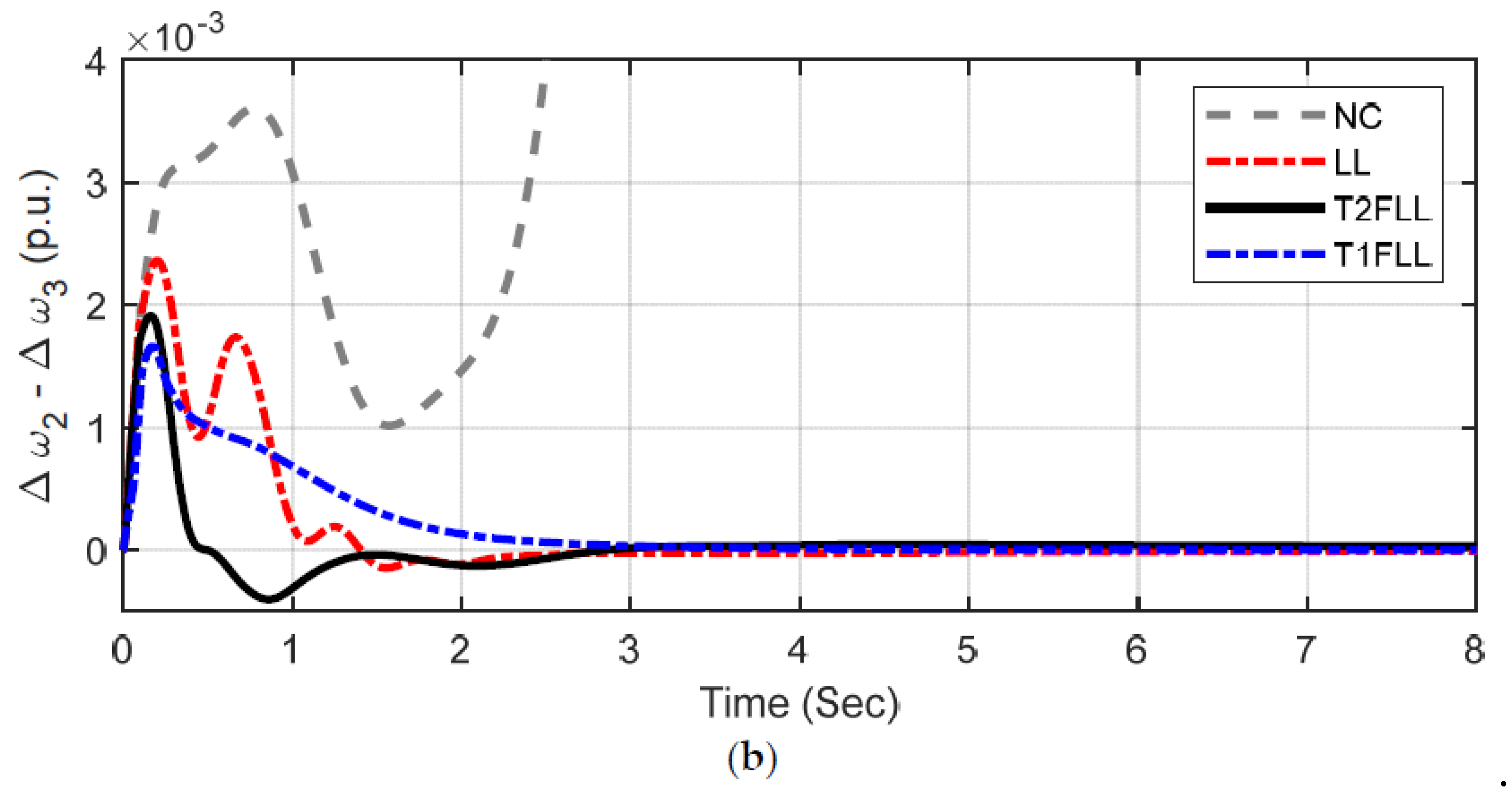
Initially, the performance of the controller is investigated under a large disturbance scenario. A 3-phase fault (self-clearing) of 5 cycles is assumed at the middle of one transmission line at t = 0 s. The local and inter-area modes of oscillations with the hADE-PS-tuned LL, T1FLL, and T2FLL controllers are shown in Figure 12a,b. For comparison, the responses without any control are also presented in Figure 12a,b.
It is obvious from Figure 12a,b that the system loses stability without control, and stability is maintained with all the controllers. It is also evident from Figure 12a,b that improved system damping performance with fewer overshoots/undershoots is attained with the proposed T2FLL controller compared to the T1FLL and LL controllers.

5.2.2. Scenario 2: Line Outage Disturbance Condition

In this scenario, one of the two tie-lines is removed at t = 0 sec and reclosed after 5 cycles. The responses are exposed in Figure 13a,b. It is evident from Figure 13a,b that in this scenario also, the system loses stability without control, and improved responses are attained with the T2FLL controller related to the T1FLL and LL controllers.

5.2.3. Scenario 3: Small Disturbance Condition

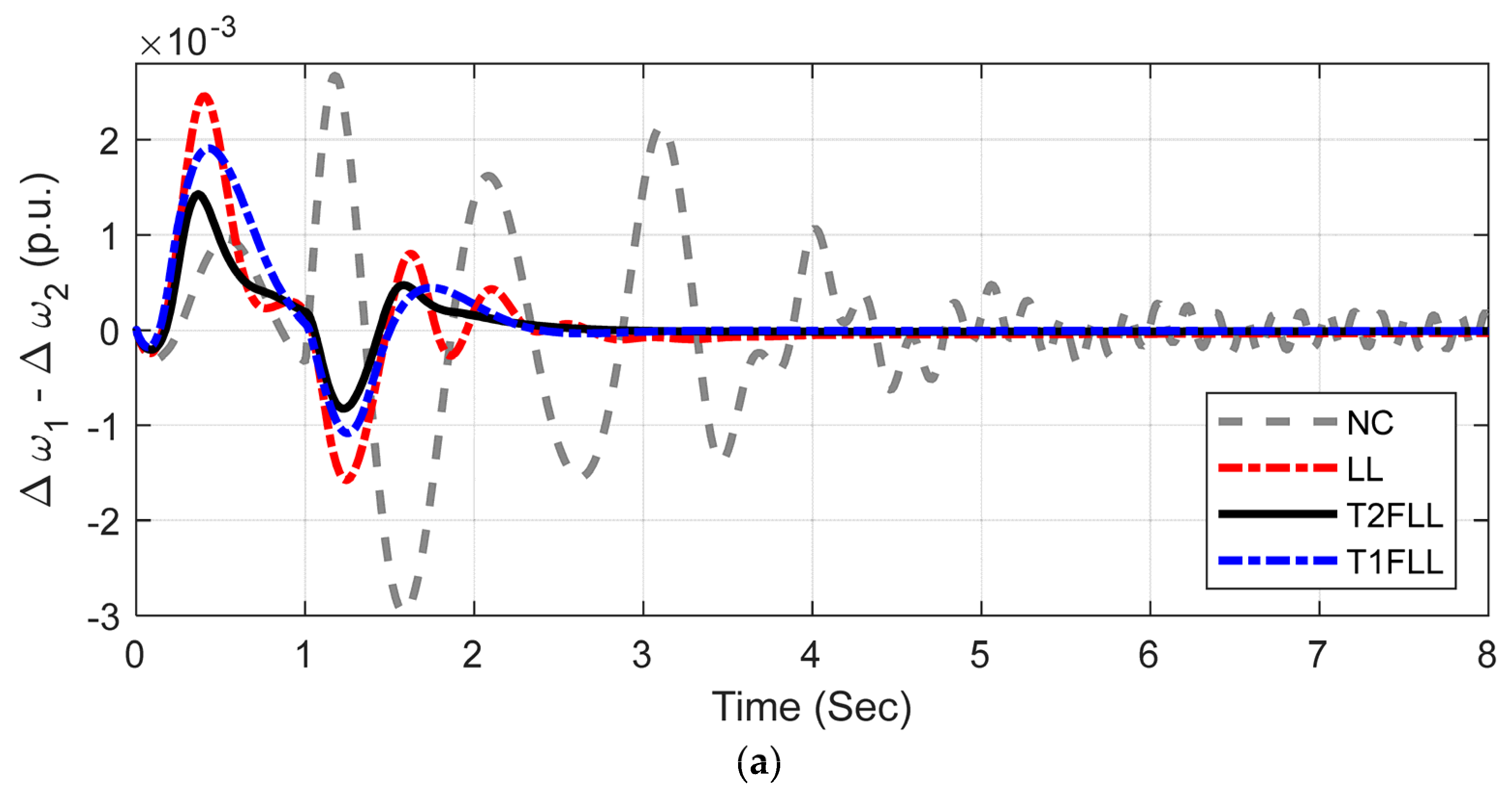
To simulate the small disturbance condition, the voltage reference of M1 is increased by 5% for 12 cycles, and the responses are revealed in Figure 14a,b. It is obvious from Figure 14 that both the LL and T2FLL controllers maintain stability and T2FLL is superior to the T1FLL and LL controller, providing significantly more damping to all modes. For better illustration, objective function values for MMPS for the above scenarios are presented in Table 7. It can be noticed from Table 7 that fewer J values are attained with T2FLL for all the scenarios compared to T1FLL and LL controllers.

6. Conclusions

In this present work, type-2 fuzzy lead–lag (T2FLL)-structured SSSC and PSS damping controller are suggested for stability improvement of power systems. The controllers are coordinated and designed using a hybrid adaptive DE-PS (hADE-PS) technique.
Initially, a SMIB system with a lead–lag controller is considered, and the dominance of hADE-PS as related to DE, PSO, and GA is demonstrated. It is noticed that for the SMIB system with LL controller, the percentage reduction in ITAE value with hADE-PS related to GA, PSO, and DE methods are 23.56%, 17.53%, and 10.53%, respectively.
Next, the T2FLL controller is designed and it is found that there is a reduction of 10.13% and 15.08% in J value with T2FLL related to the T1FLL and LL controller, respectively. Various disturbance scenarios such as large disturbance, small disturbance, and changed loading/fault location are simulated and it is seen that improved damping is attained with T2FLL related to the T1FLL and LL controllers for all the scenarios.
The study is also applied to an MMPS and it is noticed that though all controllers maintain synchronism under various scenarios, an improved system response is attained with T2FLL compared to others. For all the scenarios, the proposed T2FLL is superior to the T1FLL and LL controller, providing significantly more damping to all modes.
Extension of the presented control scheme to a large scale power system is the future scope of this work. Additionally, new hybrid optimization techniques could be implemented for improving the system performance further.

Author Contributions

Conceptualization, P.K. and S.P.; data curation, P.K.; formal analysis, P.K., S.P. and A.Y.A.; funding acquisition, H.A., A.Y.A. and S.S.M.G.; investigation, P.K., S.P., A.Y.A. and S.S.M.G.; methodology, P.K.; project administration, H.A., A.Y.A. and S.S.M.G.; resources, S.P. and S.S.M.G.; software, S.P.; supervision, S.P. and A.Y.A.; validation, P.K., S.P., H.A. and A.Y.A.; visualization, P.K., S.P. and S.S.M.G.; writing—original draft, P.K.; writing—review and editing, S.P., H.A., A.Y.A. and S.S.M.G. All authors have read and agreed to the published version of the manuscript.

Funding

This work was supported by Taif University Researchers Supporting Project number (TURSP-2020/34), Taif University, Taif, Saudi Arabia.

Institutional Review Board Statement

Not applicable.

Informed Consent Statement

Not applicable.

Data Availability Statement

Not applicable.

Acknowledgments

The authors appreciate Taif University Researchers Supporting Project number (TURSP-2020/34), Taif University, Taif, Saudi Arabia for supporting this work.

Conflicts of Interest

The authors declare no conflict of interest.

Appendix A

SMIB Parameters
Generator: Nominal power (SB),voltage (VB) and frequency (f): 2100 MVA, 13.8 kV, 60 Hz
Parameters: Stator resistance (RS): 2.8544 × 10⁻³, Reactances: Xd = 1.305, Xq = 0.474, X’d = 0.296, X’q = 0.243, X’’d = 0.252, X’’q = 0.18, Td = 1.01s, T’d = 0.053s, T’’qo = 0.1s.
Inertia constant (H) and pole pairs (p): 3.7 s and 32
Excitation System:
Gains (KA) and time constant (TA) of regulator: 200 and 0.001 s
Gains (Ke) and time constant (Te) of exciter: 1 and 0 s
Gains (Kf) and time constant (Tf) of damping filter: 0.001 and 0.1 s
Low-pass filter time constant (TLP): = 0.02 s,
Transient gain reduction (Tb, Tc): 0
Regulator output limits (Efmax/Efmin) and gain (Kp): 7/0 and 0
Hydraulic Turbine and Governor:
Gains (Ka) and time constant (Ta) of Servo-motor: 3.33 and 0.07 s
Limits of Gate opening (Gmax/Gmin and Vgmax/Vgmin): 0.97518/0.01 and 0.01/−0.1 pu/s
Permanent droop (Rp): = 0.05, Hydraulic turbine: β = 0, T w = 2.67 sPID regulator (Kp, Ki, Kd, Td): 1.163, 0.105, 0, 0.01 s
Transformer:
Nominal power (SB) = 2100 MVA, Winding connection: D1/Yg, Primary and secondary voltage (V1/V2): 13.8/500 kV, Resistance (R): 0.002 p.u., Inductances (L1/L2): 0/0.12, Magnetization resistance (Rm) and reactance (Lm): 500 Ω
Transmission line:
Line length and no. of phases: 300 km, 3-Ph, Resistance per unit length (R1/R0): 0.02546/0.3864 Ω/ km, Inductance per unit length (L1/L0): 0.9337 × 10⁻³ /4.1264 × 10−3 H/km, Capacitance per unit length (C1/C0): 12.74 × 10⁻⁹/7.751 × 10−9 F/ km
Load at Bus2:
250 MW (500 kV, 60 Hz, Y-grounded)
Kundur’s 4-machine 2-area system
Generator: Nominal powers: 900 MVA each, Nominal voltages: 20 kV each, frequency (f): 60 Hz
Parameters: Stator resistance (RS): 2.8544 × 10⁻³, Reactances: Xd = 1.8, Xq = 1.7, X’d = 0.3, X’q = 0.55, X’’d = 0.25, X’’q = 0.25, T’do = 8 s, T’’do = 0.03 s, T’qo = 0.4 s, T’’qo = 0.05 s, Stator resistance (RS): 0.0025 Ω
Excitation Systems: Each same as SMIB system
Steam Turbine and Governor:
Regulator Gain (Kp) = 1, Permanent drooop (Rp): 0.05, Dead zone (Dz): 0, Speed relay and servo-motor time constants (Tsr/Tsm): 0.001/0.15 s, Limits of gate opening (Gmax/Gmin and Vgmax/Vgmin): 4.496/0 and 0.01/−0.1 pu/s, time constants of steam turbine (T1, T2, T3, T4): 0, 10, 3.3, 0.5 s, Turbine torque fractions (F1, F2, F3, F4): 0, 0.36, 0.36, 0.28
Transformers:
Nominal powers = 900 MVA each, Winding connection: D1/Yg, Primary and secondary voltage (V1/V2): 20/230 kV, Resistance (R): 1 × 10⁻⁶, Inductances (L1/L2): 0/0.15, Magnetization resistance (Rm) and reactance (Lm): 500 Ω
Transmission lines:
Distributed parameter line (110 km line sections) and PI section line (10 km and 25 km line sections)
Line length and n0. of phases: 300 km, 3-Ph, Resistance per unit length (R1/R0): 0.0529/1.61 Ω/km, Inductance per unit length (L1/L0): 0.0014/0.0061 H/km, Capacitance per unit length (C1/C0): 8.7749 × 10⁻⁹/5.2489 × 10−9 F/km
Loads:
Area-1: Active power: 967 MW, Inductive reactive power: 100 MVAR, Capacitive reactive power: 387 MVAR
Area-2: Active power: 1767 MW, Inductive reactive power: 100 MVAR, Capacitive reactive power: 537 MVAR
SSSC Data
Converter rating: = 100 MVA, Nominal voltage: 500 kV, Frequency (f): 60 Hz, Maximum rate of change in reference voltage = 3 pu/s, Converter impedances (R/L): 0.00533/0.16, DC link voltage: 40 kV, DC link equivalent capacitance: 375 × 10−6 F, Injected Voltage regulator gains (KP /KI): 0.00375/0.1875, DC Voltage regulator gains (KP/KI ): 0.1 × 10⁻³/20 × 10−3, Limits of injected voltage: ± 0.2

References

  1. Yu, Y.N. Electric Power System Dynamics; Academic Press: New York, NY, USA, 1983. [Google Scholar]
  2. Sauer, P.W.; Pai, M.A. Power System Dynamics and Stability; Prentice-Hall: Englewood Cliffs, NJ, USA, 1998. [Google Scholar]
  3. Gyugyi, L.; Schauder, C.D.; Sen, K.K. Static synchronous series compensator: A solid-state approach to the series compensation of transmission lines. IEEE Trans. Power Deliv. 1997, 12, 406–417. [Google Scholar] [CrossRef]
  4. Panda, S.; Ardil, C. Robust coordinated design of multiple power system stabilizers using particle swarm optimization technique. Int. J. Electr. Syst. Sci. Eng. 2008, 1, 41–48. [Google Scholar]
  5. Panda, S.; Padhy, N.P. Robust power system stabilizer design using particle swarm optimization technique. Int. J. Electr. Syst. Sci. Eng. 2008, 1, 2260–2267. [Google Scholar]
  6. Abdel-Magid, Y.L.; Abido, M.A.; Al-Baiyat, S.; Mantawy, A.H. Simultaneous stabilization of multi-machine stabilizers via genetic algorithm. IEEE Trans. Power Syst. 1999, 14, 1428–1439. [Google Scholar] [CrossRef]
  7. Sebaa, K.; Boudour, M. Optimal locations and tuning of robust power system stabilizer using genetic algorithms. Int. J. Electr. Power Syst. Res. 2009, 79, 406–416. [Google Scholar] [CrossRef]
  8. Paul, S.; Roy, P.K. Oppositional cuckoo optimization algorithm for optimal tuning of power system stabilizers. In Proceedings of the Michael Faraday IET International Summit, Kolkata, India, 12–13 September 2015; pp. 176–181. [Google Scholar]
  9. Abido, M.A. Robust design of multi-machine power system stabilizers using simulated annealing. IEEE Trans Energy Convers. 2000, 15, 297–304. [Google Scholar] [CrossRef]
  10. Abdel-Magid, Y.L.; Abido, M.A.; Mantawy, A.H. Robust tuning of power system stabilizers in multi-machine power systems. IEEE Trans Power Syst. 2000, 15, 735–740. [Google Scholar] [CrossRef] [Green Version]
  11. Mishra, S.; Tripathy, M.; Nanda, J. Multi-machine power system stabilizer design by rule based bacteria foraging. Int. J. Electr. Power Syst. Res. 2007, 77, 1595–1607. [Google Scholar] [CrossRef]
  12. Jolfaei, M.G.; Sharaf, A.M.; Shariatmadar, S.M.; Poudeh, M.B. A hybrid PSS–SSSC GA-stabilization scheme for damping power system small signal oscillations. Electr. Power Energy Syst. 2016, 75, 337–344. [Google Scholar] [CrossRef]
  13. Falehi, A.D.; Rostami, M.; Doroudi, A.; Ashrafian, A. Optimization and coordination of SVC-based supplementary controllers and PSSs to improve power system stability using a genetic algorithm. Turk. J. Elec. Eng. Comp. Sci. 2012, 20, 639–654. [Google Scholar]
  14. Khadanga, R.K.; Satapathy, J.K. Time delay approach for PSS and SSSC based coordinated controller design using hybrid PSO–GSA algorithm. Int. J. Electr. Power Energy Syst. 2015, 71, 262–273. [Google Scholar] [CrossRef]
  15. Tripathy, M.; Mishra, S. Coordinated tuning of PSS and TCSC to improve hopf bifurcation margin in multi-machine power system by a modified bacteria foraging algorithm. Int. J. Electr. Power Energy Syst. 2015, 66, 97–109. [Google Scholar] [CrossRef]
  16. Ali, E.S.; Abd-Elazim, S.M. Coordinated design of PSSs and TCSC via bacterial swarm optimization algorithm in a multi-machine power system. Int. J. Electr. Power Energy Syst. 2012, 36, 84–92. [Google Scholar] [CrossRef]
  17. Shayeghi, H.; Safari, A.; Shayanfar, H.A. PSS and TCSC damping controller coordinated design using PSO in multi-machine power system. Energy Convers Manag. 2010, 51, 2930–2937. [Google Scholar] [CrossRef]
  18. Dadfar, S.; Wakil, K.; Khaksar, M.; Rezvani, A.; Miveh, M.R.; Gandomkar, M. Enhanced control strategies for a hybrid battery/photovoltaic system using FGS-PID in grid-connected mode. Int. J. Hydrog. Energy 2019, 44, 14642–14660. [Google Scholar] [CrossRef]
  19. Khaksar, M.; Rezvani, A.; Moradi, M.H. Simulation of novel hybrid method to improve dynamic responses with PSS and UPFC by fuzzy logic controller. Neural Comput. Appl. 2018, 29, 837–853. [Google Scholar] [CrossRef]
  20. Rezvani, A.; Esmaeily, A.; Etaati, H.; Mohammadinodoushan, M. Intelligent hybrid power generation system using new hybrid fuzzy-neural for photovoltaic system and RBFNSM for wind turbine in the grid connected mode. Front. Energy 2019, 13, 131–148. [Google Scholar] [CrossRef]
  21. Ray, P.K.; Paital, S.R.; Mohanty, A.; Eddy, F.Y.S.; Krishnan, A.; Gooi, H.B.; Amaratunga, G.A.J. A hybrid firefly-swarm optimized fractional order interval type-2 fuzzy PID-PSS for transient stability improvement. IEEE Trans. Ind. Appl. 2019, 55, 6486–6498. [Google Scholar] [CrossRef]
  22. Elazim, S.M.A.; Ali, E.S. Optimal power system stabilizers design via cuckoo search algorithm. Int. J. Electr. Power Energy Syst. 2016, 75, 99–107. [Google Scholar] [CrossRef]
  23. Ali, E.S. Optimization of power system stabilizers using BAT search algorithm. Int. J. Electr. Power Energy Syst. 2014, 61, 683–690. [Google Scholar] [CrossRef]
  24. Elazim, S.M.A.; Ali, E.S. Optimal location of STATCOM in multimachine power system for increasing loadability by cuckoo search algorithm. Int. J. Electr. Power Energy Syst. 2016, 80, 240–251. [Google Scholar] [CrossRef]
  25. Abdelaziz, A.Y.; Ali, E.S. Static VAR compensator damping controller design based on flower pollination algorithm for a multi-machine power system. Electr. Power Compon. Syst. 2015, 43, 1268–1277. [Google Scholar] [CrossRef]
  26. Abd Elazim, S.M.; Ali, E.S. Optimal SSSC design for damping power systems oscillations via gravitational search algorithm. Int. J. Electr. Power Energy Syst. 2016, 82, 161–168. [Google Scholar] [CrossRef]
  27. Elazim, S.M.A.; Ali, E.S. Coordinated design of PSSs and SVC via bacteria foraging optimization algorithm in a multi-machine power system. Int. J. Electr. Power Energy Syst. 2012, 41, 44–53. [Google Scholar] [CrossRef]
  28. Stron, R.; Price, K. Differential evolution—A simple and efficient adaptive scheme for global optimization over continuous spaces. J. Glob. Optim. 1997, 11, 341–359. [Google Scholar] [CrossRef]
  29. Sahu, R.K.; Gorripotu, T.S.; Panda, S. A hybrid DE–PS algorithm for load frequency control under deregulated power system with UPFC and RFB. Ain Shams Eng. J. 2015, 6, 893–911. [Google Scholar] [CrossRef] [Green Version]
  30. Mohanty, P.; Sahu, R.K.; Panda, S. A novel hybrid many optimizing liaisons gravitational search algorithm approach for AGC of power systems. Autom. J. Control. Meas. Electron. Comput. Commun. 2020, 61, 158–178. [Google Scholar] [CrossRef]
  31. Khadanga, R.K.; Kumar, A.; Panda, S. A hybrid shuffled frog-leaping and pattern search algorithm for load frequency controller design of a two-area system composing of PV grid and thermal generator. Int. J. Numer. Modeling 2020, 33, e2694. [Google Scholar] [CrossRef]
  32. Rout, B.D.; Pati, B.B.; Panda, S. A hybrid modified differential evolution-pattern search approach for SSSC based damping controller design under communication constraints. Int. J. Syst. Assur. Eng. Manag. 2018, 9, 962–971. [Google Scholar] [CrossRef]
  33. Zhang, J.; Sanderson, A.C. JADE: Adaptive differential evolution with optional external archive. IEEE Trans Evol. Comput. 2009, 13, 945–958. [Google Scholar] [CrossRef]
  34. Wang, Y.; Cai, Z.; Zhang, Q. Differential evolution with composite trial vector generation strategies and control parameters. IEEE Trans Evol. Comput. 2011, 15, 55–66. [Google Scholar] [CrossRef]
  35. Tanabe, R.; Fukunaga, A. Success-history based parameter adaptation for differential evolution. In Proceedings of the IEEE CEC, Cancun, Mexico, 20–23 June 2013; pp. 71–78. [Google Scholar]
  36. Mohanty, P.; Sahu, R.K.; Sahoo, D.K.; Panda, S. Adaptive differential evolution and pattern search tuned fractional order fuzzy PID for frequency control of power systems. Int. J. Model. Simul. 2022, 42, 240–254. [Google Scholar] [CrossRef]
  37. SimPowerSystems 4.3 User’s Guide. Available online: http://www.mathworks.com/products/simpower/ (accessed on 3 March 2022).
  38. Kundur, P. Power System Stability and Control; McGraw-Hill: Irvine, CA, USA, 1994; p. 813, Example 12.6. [Google Scholar]
  39. Chintu, J.M.; Sahu, R.K.; Panda, S. Adaptive differential evolution tuned hybrid fuzzy PD-PI controller for automatic generation control of power systems. Int. J. Ambient. Energy 2019, 17, 1–6. [Google Scholar] [CrossRef]
  40. Liu, J.; Lampinen, J. A fuzzy adaptive differential evolution algorithm. Soft Comput. 2005, 9, 448–462. [Google Scholar] [CrossRef]
  41. Gamperle, R.; Muller, S.D.; Koumoutsakos, P. A parameter study for differential evolution. Adv. Intell. Syst. Fuzzy Syst. Evol. Comput. 2002, 10, 293–298. [Google Scholar]
  42. Ali, M.M.; Torn, A. Population set-based global optimization algorithms: Some modifications and numerical studies. Comput. Oper. Res. 2004, 31, 1703–1725. [Google Scholar] [CrossRef] [Green Version]
  43. Biswas, P.P.; Suganthan, P.N.; Wu, G.; Amaratunga, G.A. Parameter estimation of solar cells using datasheet information with the application of an adaptive differential evolution algorithm. Renew. Energy 2019, 132, 425–438. [Google Scholar] [CrossRef]
  44. Panda, S.; Padhy, N.P. Comparison of Particle Swarm Optimization and Genetic Algorithm for FACTS-based Controller Design. Appl. Soft Comput. 2008, 8, 1418–1427. [Google Scholar] [CrossRef]
  45. Mohanty, B.; Panda, S.; Hota, P.K. Controller parameters tuning of differential evolution algorithm and its application to load frequency control of multi-source power system. Int. J. Electr. Power Energy Syst. 2014, 54, 77–85. [Google Scholar] [CrossRef]
  46. Swain, S.C.; Panda, S.; Mahapatra, S. A multi-criteria optimization technique for SSSC based power oscillation damping controller design. Ain Shams Eng. J. 2016, 7, 553–565. [Google Scholar] [CrossRef] [Green Version]
  47. Panda, S.; Yegireddy, N. Multi-input single output SSSC based damping controller design by a hybrid improved differential evolution-pattern search approach. ISA Trans. 2015, 58, 173–185. [Google Scholar] [CrossRef] [PubMed]
  48. Panda, S.; Kiran, S.H.; Dash, S.S.; Subramani, C. A PD-type multi input single output SSSC damping controller design employing hybrid improved differential evolution-pattern search approach. Appl. Soft Comput. 2015, 32, 532–543. [Google Scholar] [CrossRef]
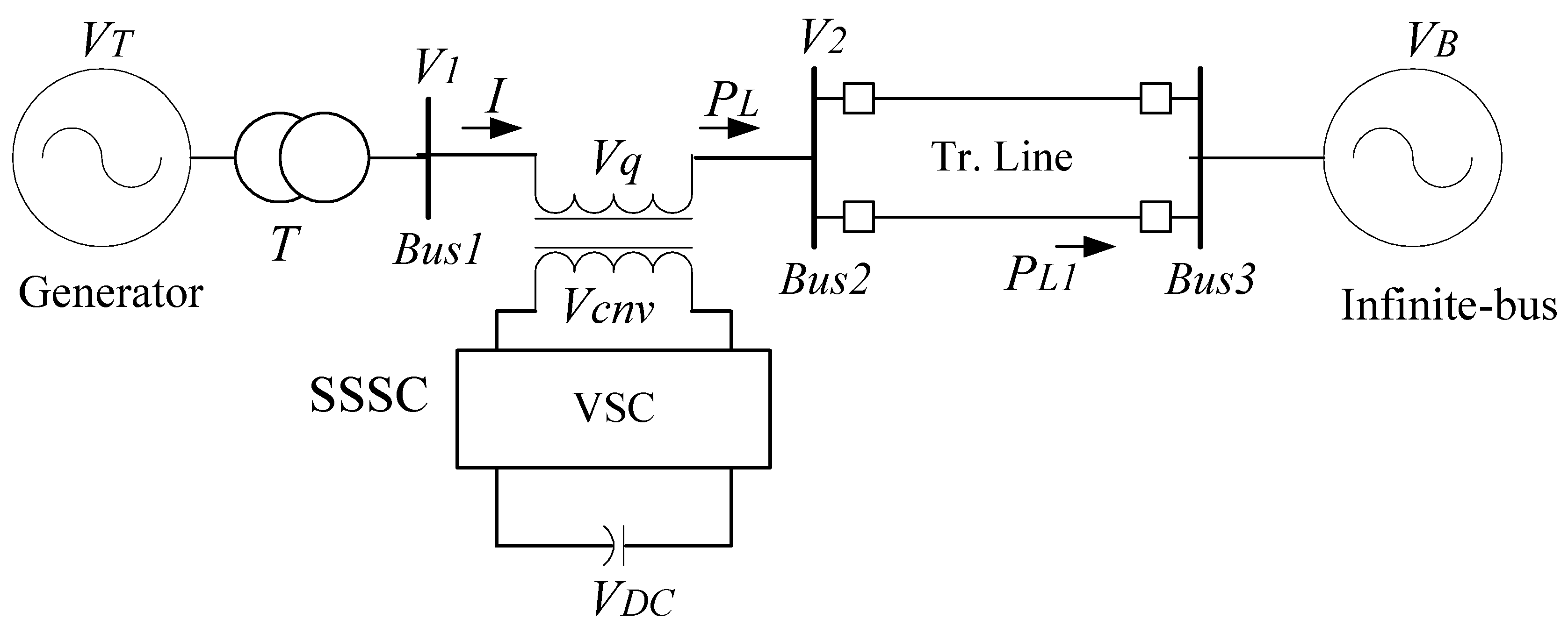
Figure 1. SMIB system.
Sustainability 14 06656 g001
Figure 2. Kundur’s 4-machine 2-area system.
Sustainability 14 06656 g002
Figure 3. SSSC-based T2FLL controller.
Sustainability 14 06656 g003
Figure 4. PSS-based T2FLL controller.
Sustainability 14 06656 g004
Figure 5. MATLAB/SIMULINK model of SMIB system.
Sustainability 14 06656 g005
Figure 6. Δω response with GA-, PSO-, DE-, and hADE-PS-tuned lead–lag controller.
Sustainability 14 06656 g006
Figure 7. System response of SMIB for Scenario 1: (a) Δω, (b) Δδ, (c) PL, (d) SSSC output, (e) PSS output.
Sustainability 14 06656 g007aSustainability 14 06656 g007b
Figure 8. Δω response of SMIB for Scenario 2.
Sustainability 14 06656 g008
Figure 9. Δω response of SMIB for Scenario 3.
Sustainability 14 06656 g009
Figure 10. MATLAB/SIMULINK model of Kundur’s 4-machine 2-area system.
Sustainability 14 06656 g010
Figure 11. MATLAB/SIMULINK model of Area 1 of Kundur’s 4-machine 4-area system.
Sustainability 14 06656 g011
Figure 12. System response of MMPS system for Scenario 1: (a) local mode; (b) inter-area mode. (a) local mode of oscillation of MMPS for Scenario 1. (b) Inter-area mode of oscillation of MMPS for Scenario 1.
Sustainability 14 06656 g012aSustainability 14 06656 g012b
Figure 13. System response of MMPS system for Scenario 2: (a) local mode; (b) inter-area mode. (a) local mode of oscillation of MMPS system for Scenario 2. (b) Inter-area mode of oscillation of MMPS system for Scenario 2.
Sustainability 14 06656 g013aSustainability 14 06656 g013b
Figure 14. System response of MMPS system for Scenario 3: (a) local mode; (b) inter-area mode. (a) Local mode of oscillation of MMPS system for Scenario 3. (b) Inter-area mode of oscillation of MMPS system for Scenario 3.
Sustainability 14 06656 g014aSustainability 14 06656 g014b
Table 1. Rule base of fuzzy controller.
ėEXNLNZERLPEXP
e
EXNEXNEXNLNLNZER
LNEXNLNEXNZERLP
ZERLNLNZERLPLP
LPLNZERLPLPEXP
EXPZERLPLPEXPEXP
Table 2. Optimized lead–lag-structured PSS and SSSC parameters for SMIB.
TechniqueControllerKiT1iT2iT3iT4iJ Value × 10−3
GASSSC74.07400.42860.05110.45231.109844.3216
PSS19.82940.14150.00110.06301.2736
PSOSSSC38.55881.06530.32180.67510.749640.9781
PSS24.25631.55461.42230.01340.4930
DESSSC50.12180.81751.13791.49610.432637.7718
PSS16.08600.15530.73171.79741.7974
hADE-PSSSSC71.52651.20061.30510.00110.001233.7926
PSS18.24750.00110.52040.00110.4981
Table 3. hADE-PS optimized T2FLL- and T1FLL-structured PSS and SSSC parameters for SMIB.
ControllerKSF1KSF2KiT1iT2iT3iT4iJ Value × 10−3
T2FLL controller
SSSC0.01050.182479.52791.99741.57741.02920.460428.6961
PSS0.01040.724149.93500.06221.69950.00121.9974
T1FLL controller
SSSC1.90931.468414.23910.01540.45381.99740.993531.9342
PSS0.32091.228530.51060.24211.78270.41721.9974
Table 4. Performance comparison under various scenarios for SMIB.
Scenario/ControllerISE
(×10−6)
ITAE
(×10−2)
ITSE
(×10−3)
IAE
(×10−6)
Overshoots
in Δω (×10−3)
Undershoots
in Δω (×10−3)
Scenario 1NC256.6942244.056343.09721493.76077.786−8.6124
LL7.73793.37922.387810.14095.0881−4.4641
T1FLL6.88633.19342.08718.84344.998−4.3516
T2FLL5.87012.869612.04137.47215.0363−3.3831
Scenario 2NC9.364242.52168.181745.98411.71481.7312
LL0.19510.49010.35860.25140.8321−0.7049
T1FLL0.16680.48620.33980.21630.7148−0.5189
T2FLL0.11620.46180.31420.15280.6732−0.3972
Scenario 3NC19.674930.58299.033848.69164.6224−4.3954
LL2.69781.8251.31213.35194.5324−2.8929
T1FLL2.48731.80111.29673.05724.5324−2.2581
T2FLL2.20421.81691.28162.736044.5324−1.8272
Table 5. Optimized lead–lag-structured PSS and SSSC parameters for multi-machine system.
ControllerKiT1iT2iT3iT4i
SSSC92.84600.08850.03084.54947.4982
PSS146.89080.04300.01822.77948.8044
PSS248.09500.01140.01553.97353.5212
PSS345.89670.07120.01283.77493.2167
PSS427.65440.09740.03193.88843.2087
Table 6. Optimized T2FLL-structured PSS and SSSC parameters for multi-machine system.
ControllerKSF1KSF2KiT1iT2iT3iT4i
T2FLL controller
SSSC0.01020.014841.05520.09900.00641.50702.9408
PSS10.75910.012624.64320.01930.00662.43212.3374
PSS21.97970.046816.50710.03940.01041.97281.5423
PSS30.07650.028437.09970.09920.00592.44743.0812
PSS41.22450.256811.05420.01550.00511.78570.9991
T1FLL controller
SSSC0.23230.51642.71410.01030.01014.94932.0462
PSS11.02060.087111.74510.01940.00663.21273.8817
PSS21.54280.435340.60190.04150.03832.34253.8154
PSS30.94950.010049.49350.01210.00604.23984.4935
PSS41.41400.049235.80820.01150.02392.40983.6268
Table 7. Objective function value comparison under various scenario for MMPS.
Scenario/ControllerScenario 1
(×10−3)
Scenario 2
(×10−3)
Scenario 3
(×10−3)
NC20,806.079821,201.195121,040.6094
LL14.522412.858617.4648
T1FLL12.636111.824513.8912
T2FLL9.995210.696110.5976
Publisher’s Note: MDPI stays neutral with regard to jurisdictional claims in published maps and institutional affiliations.