
Dynamic Simulation and Experimental Study of the HDPE Double-Walled Corrugated Pipe Grouting Robot


Abstract
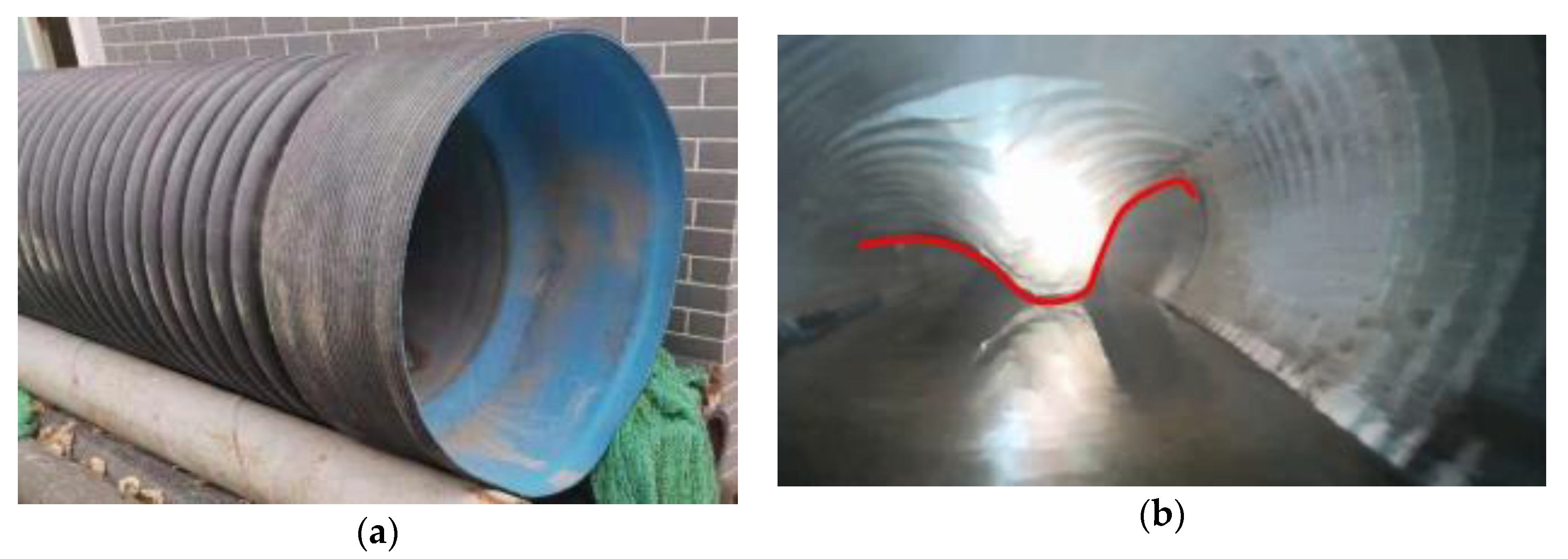
:1. Introduction
2. Overall Design and Repair Process of the Pipeline Grouting Robot
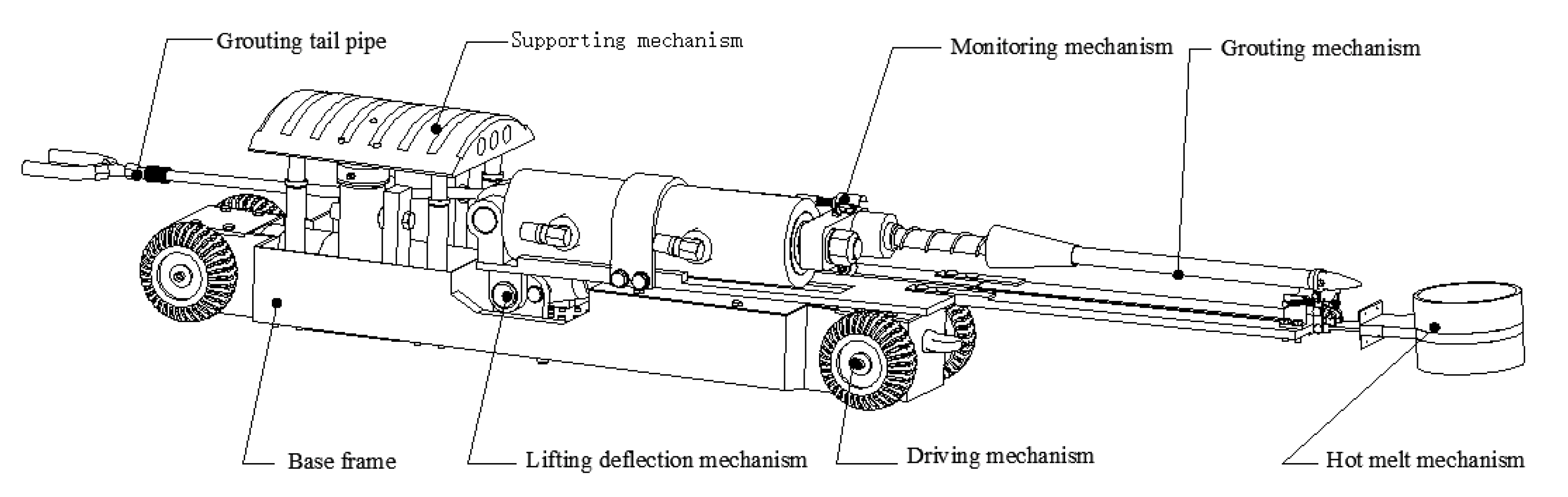
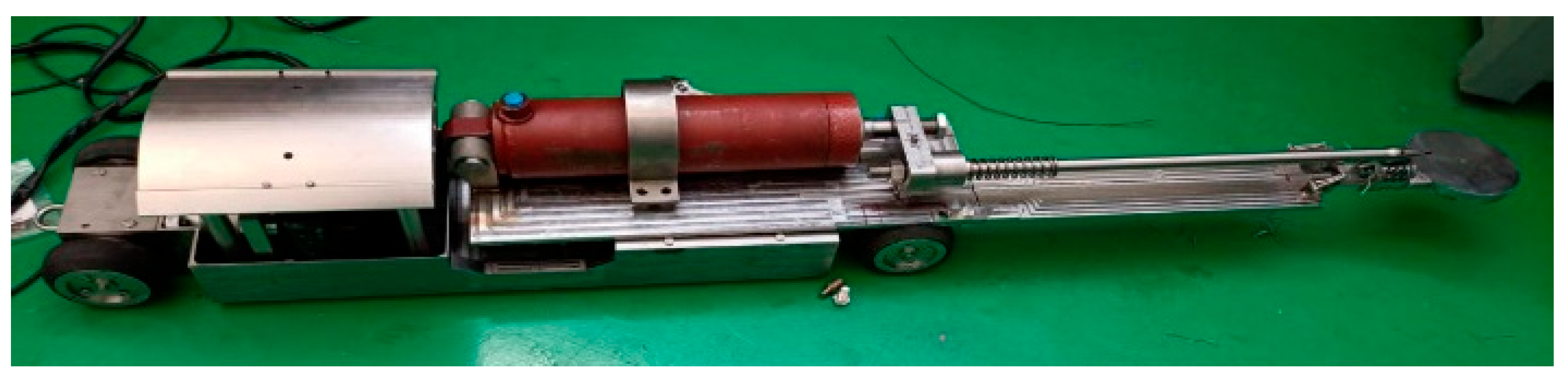
2.1. The Overall Design of the Pipeline Grouting Robot
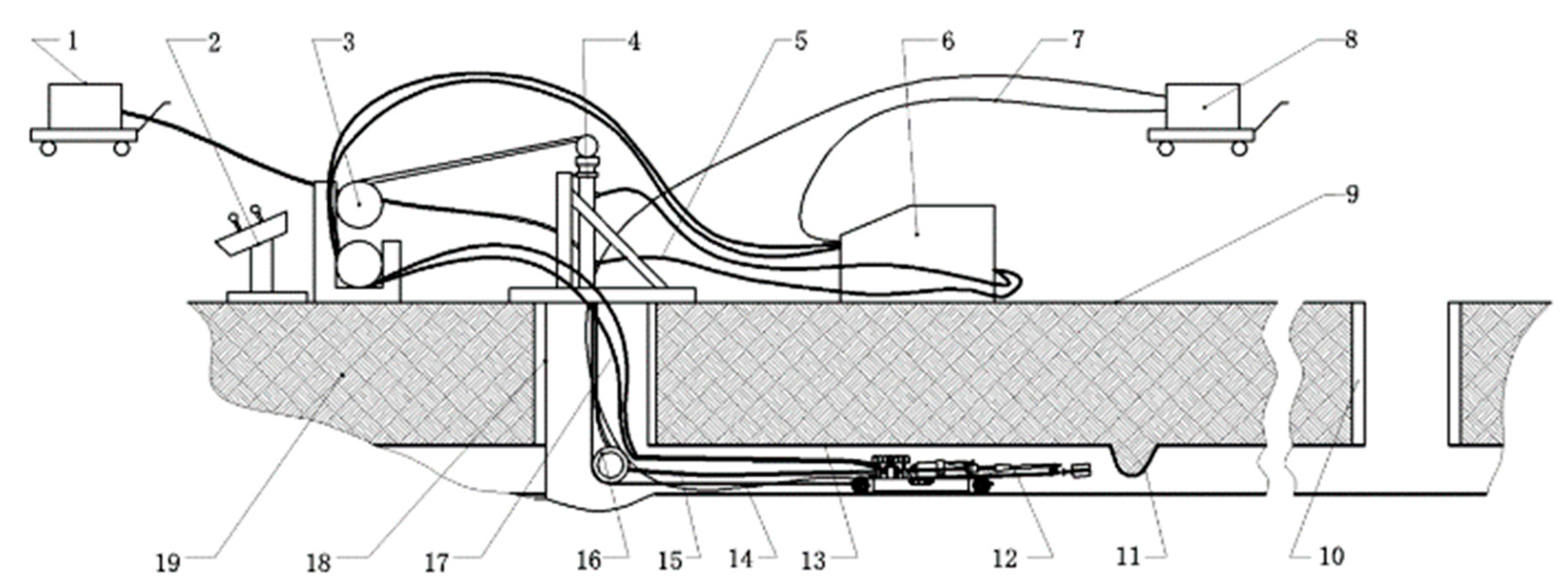
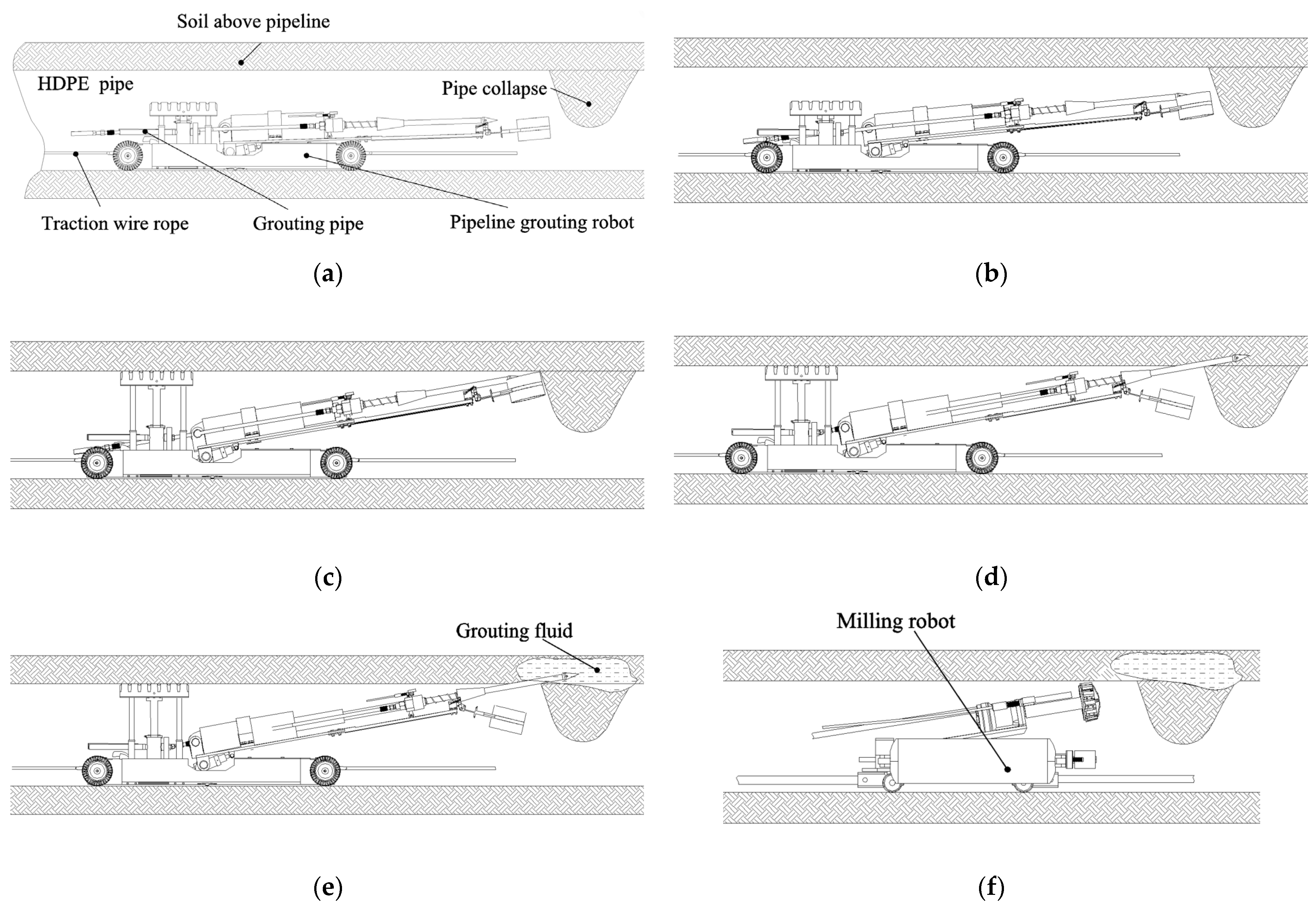
2.2. Technology Used to Repair Internal Pipeline Collapse
3. Mechanical Analysis of the Pipeline Grouting Robot
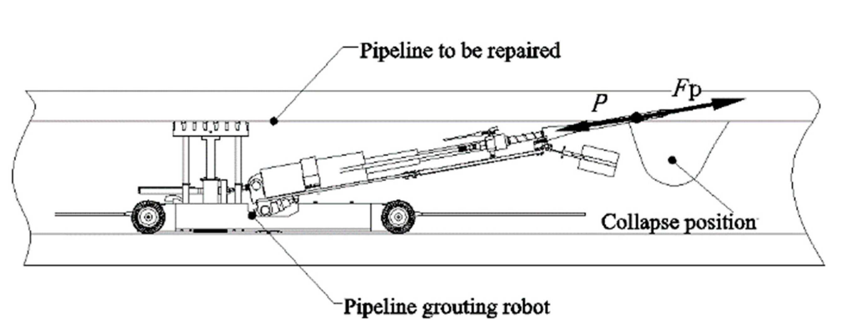
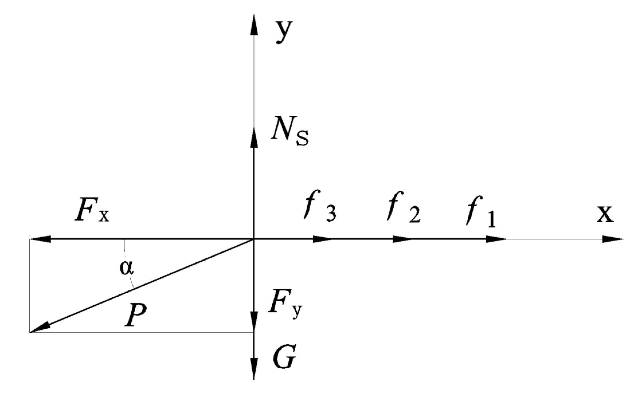
3.1. Mechanical Analysis of the Grouting Process
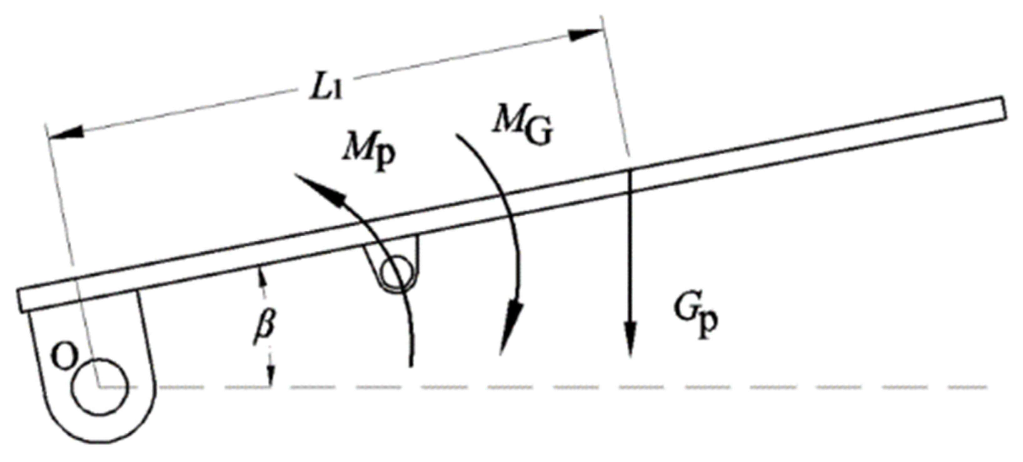
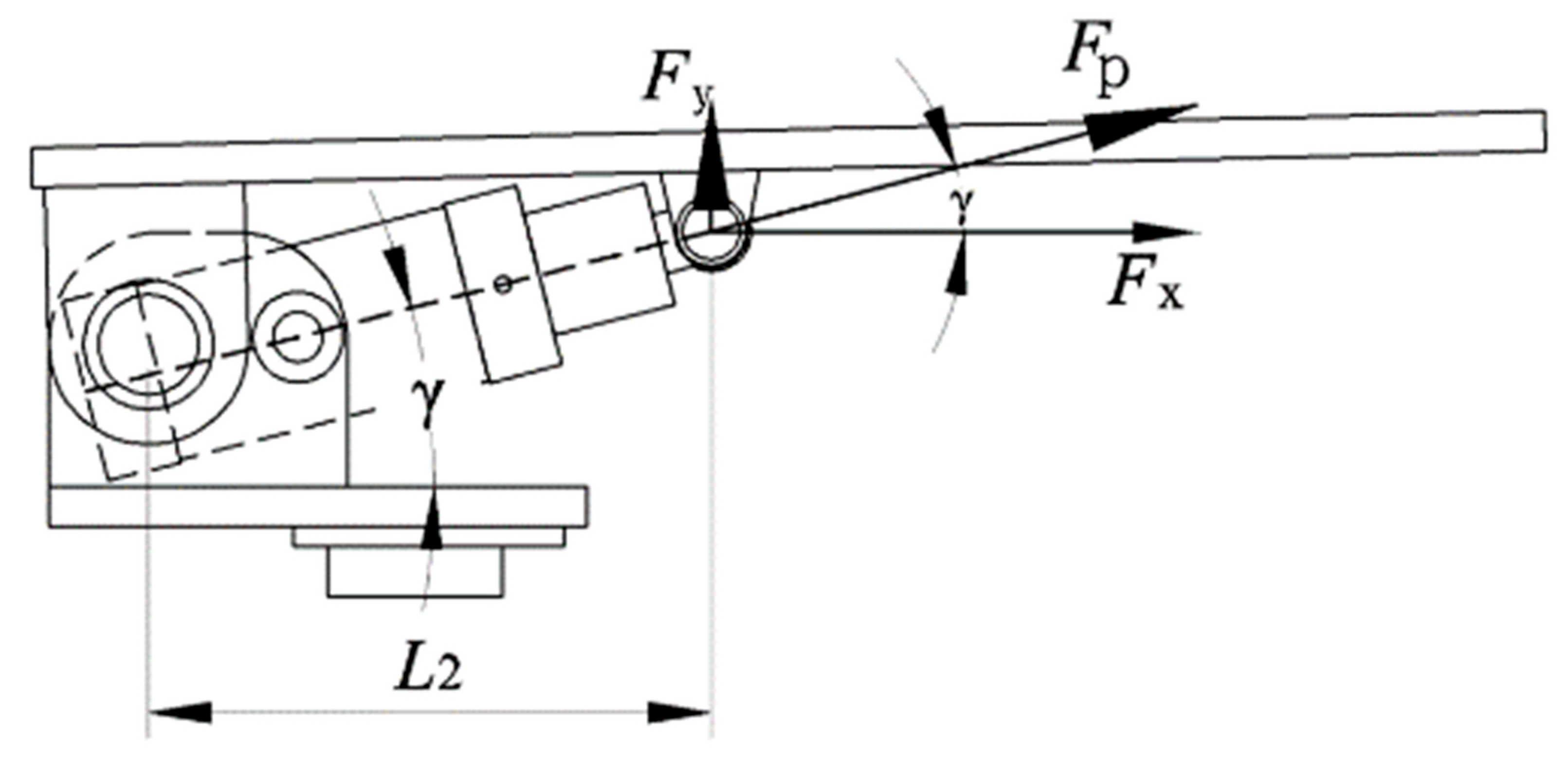
3.2. Mechanical Analysis of the Deflection and Lifting Process
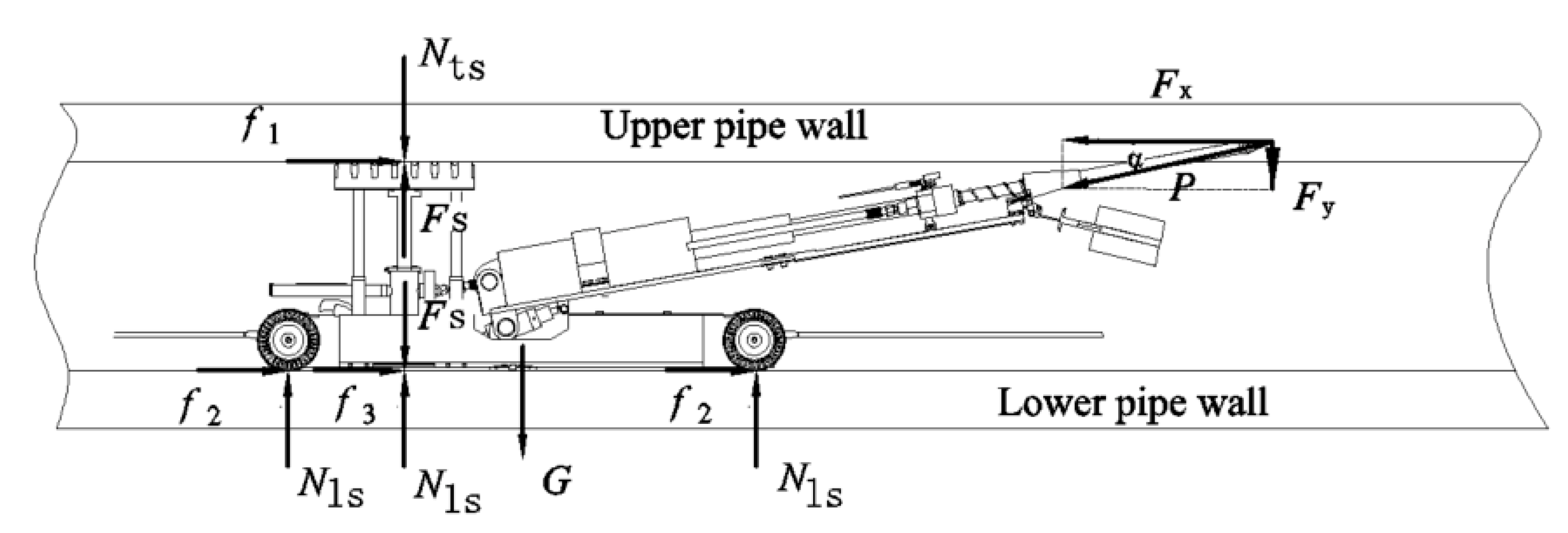
3.3. Mechanical Analysis of the Support Process
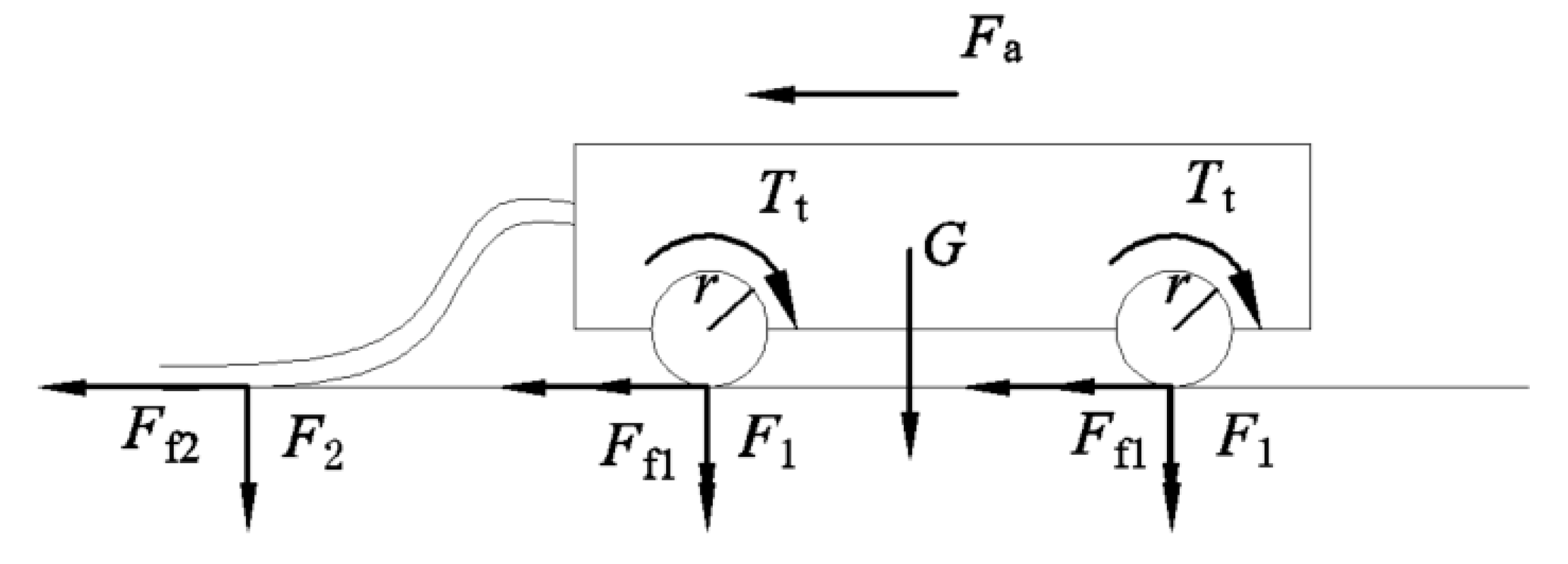
3.4. Mechanical Analysis of the Traveling Process
4. The Dynamic Simulation and Experimental Research of the Pipeline Grouting Robot
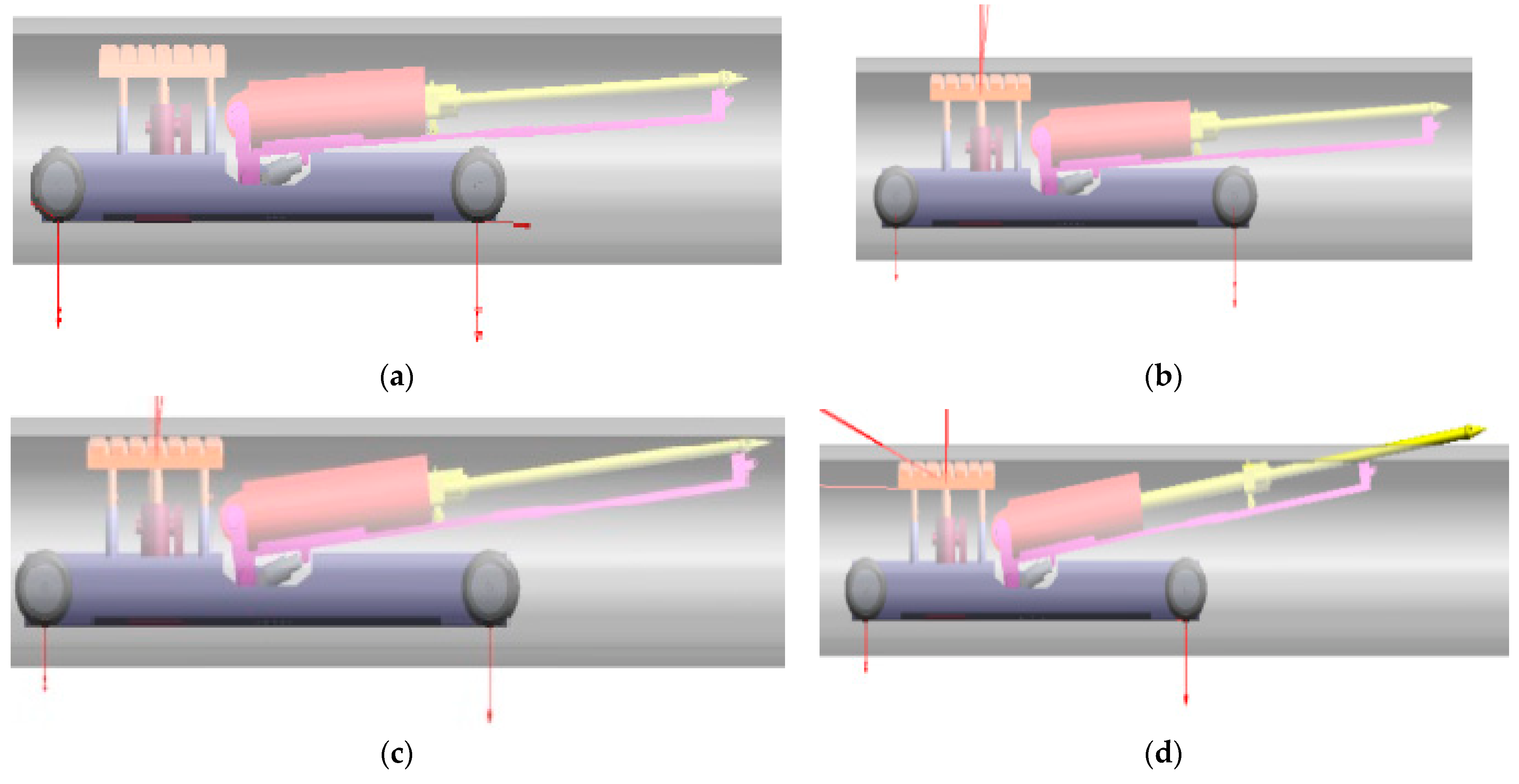
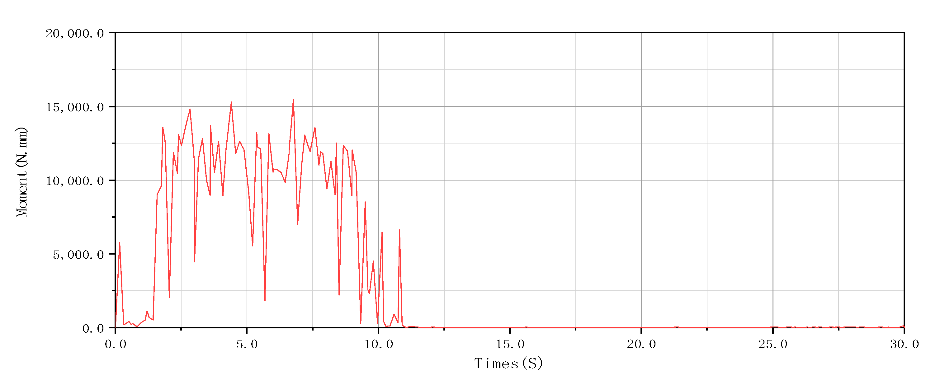
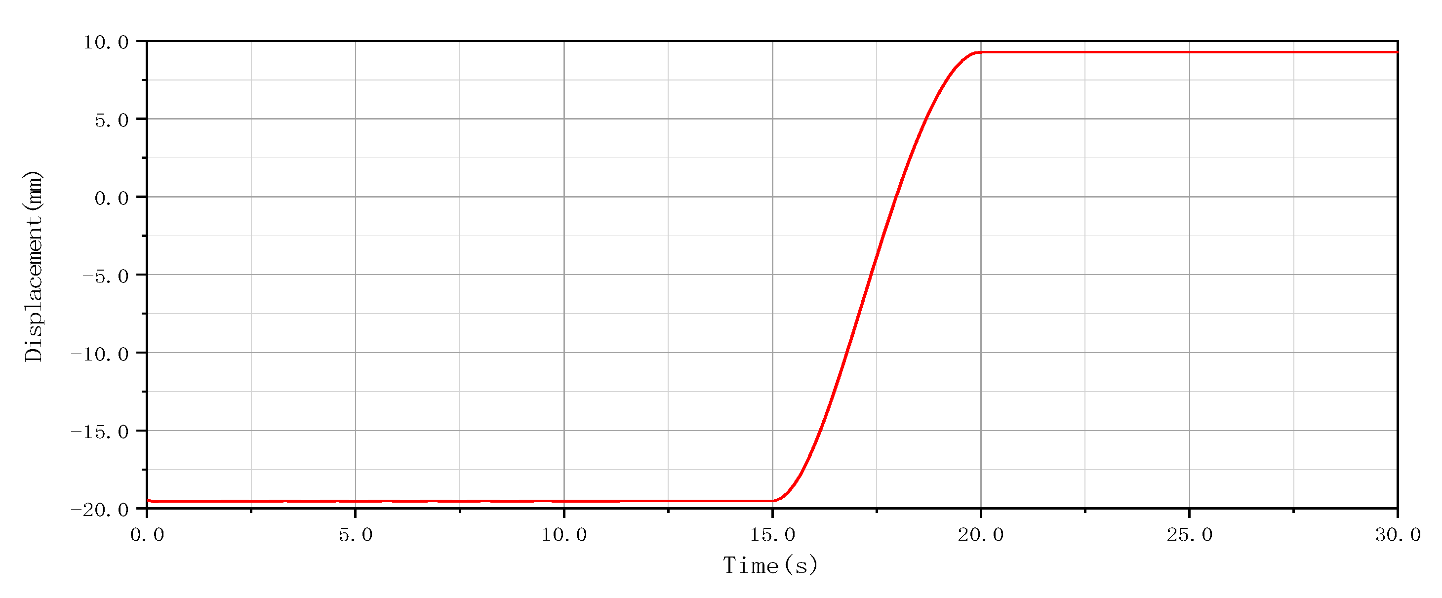
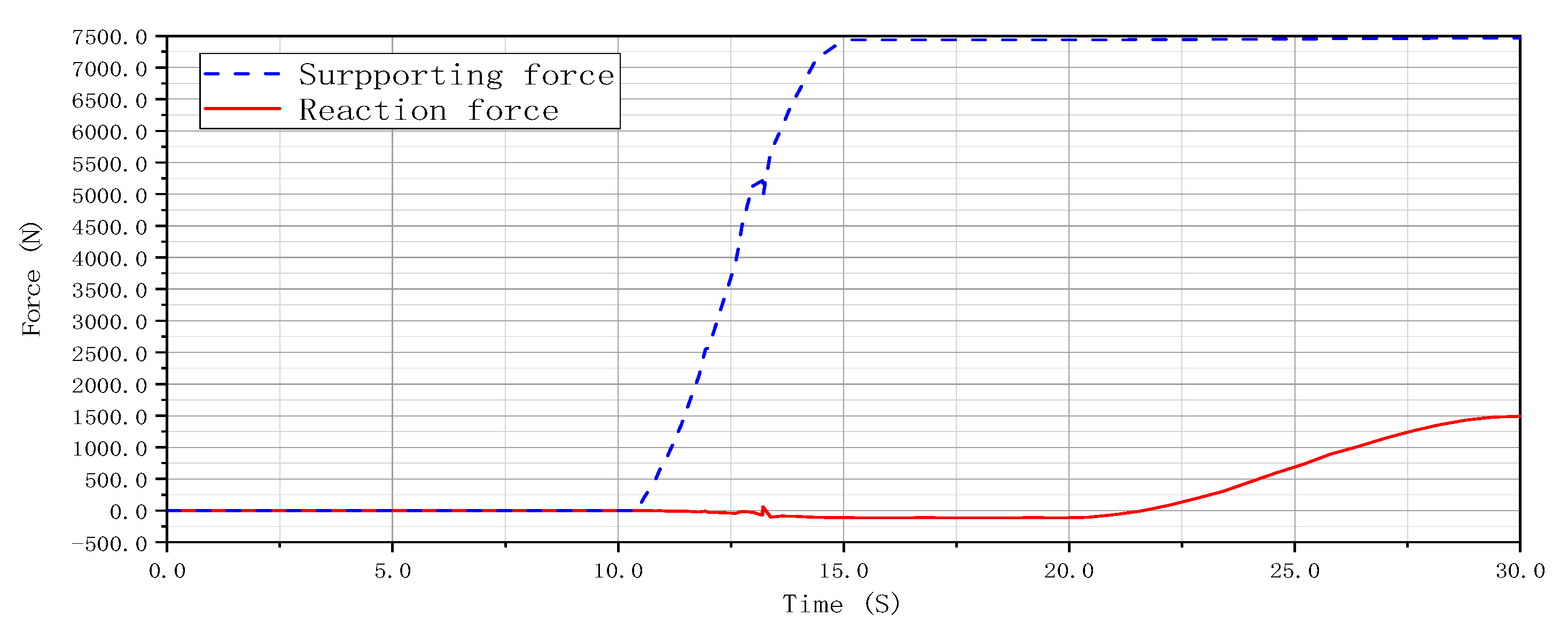
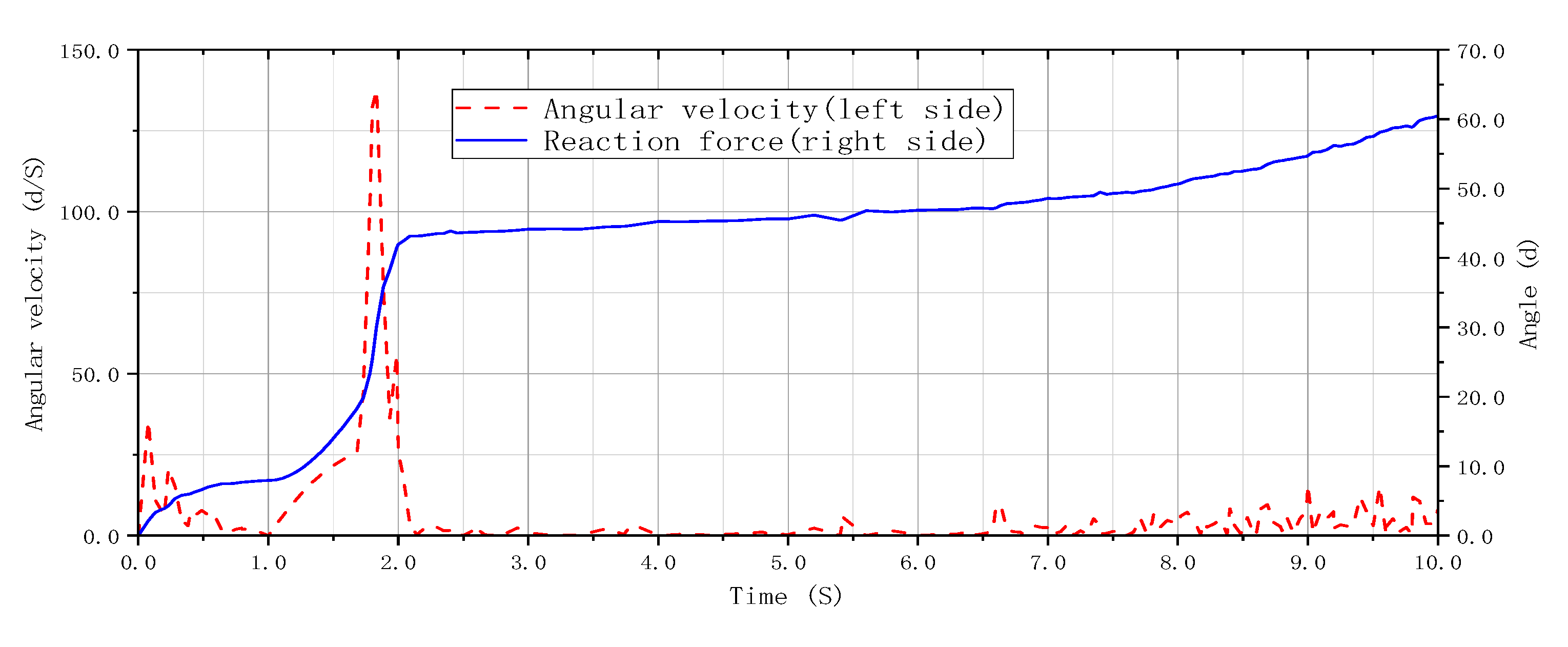
4.1. Dynamic Simulation of the Pipeline Grouting Robot
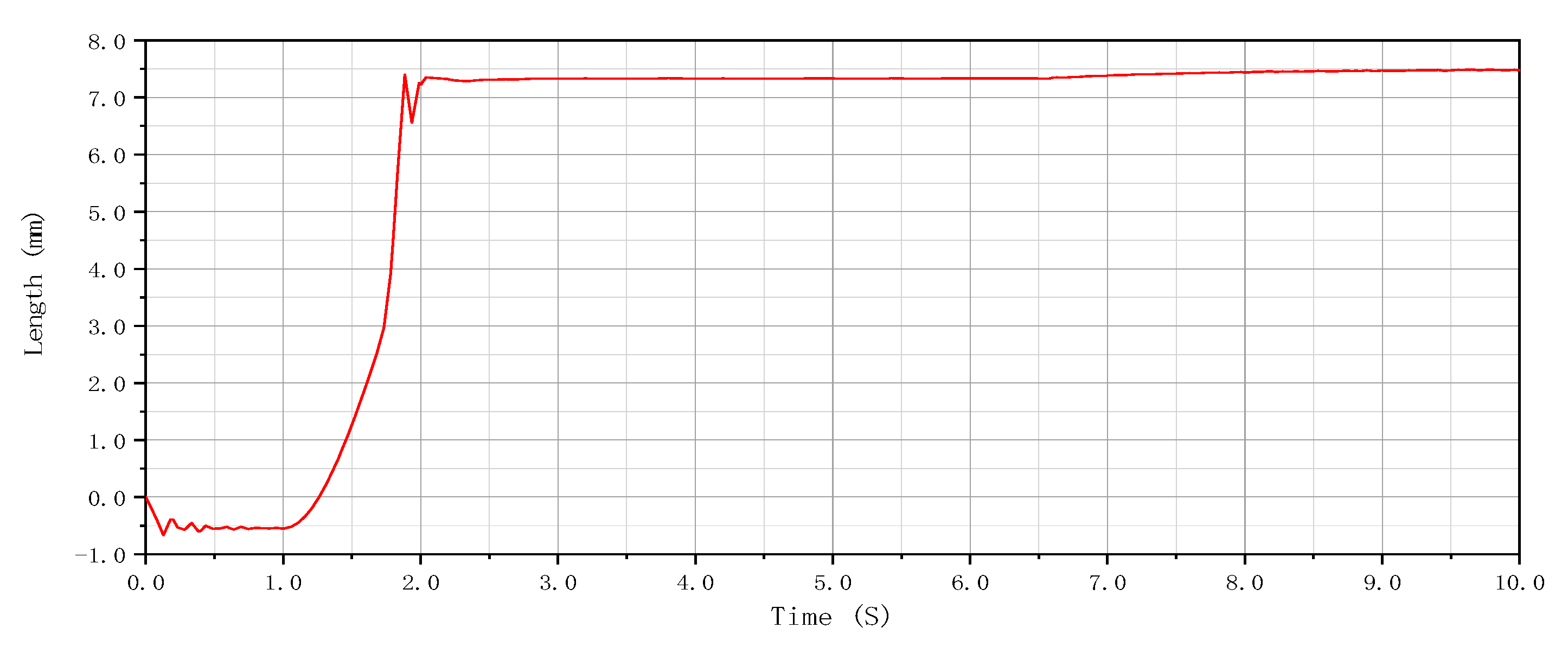
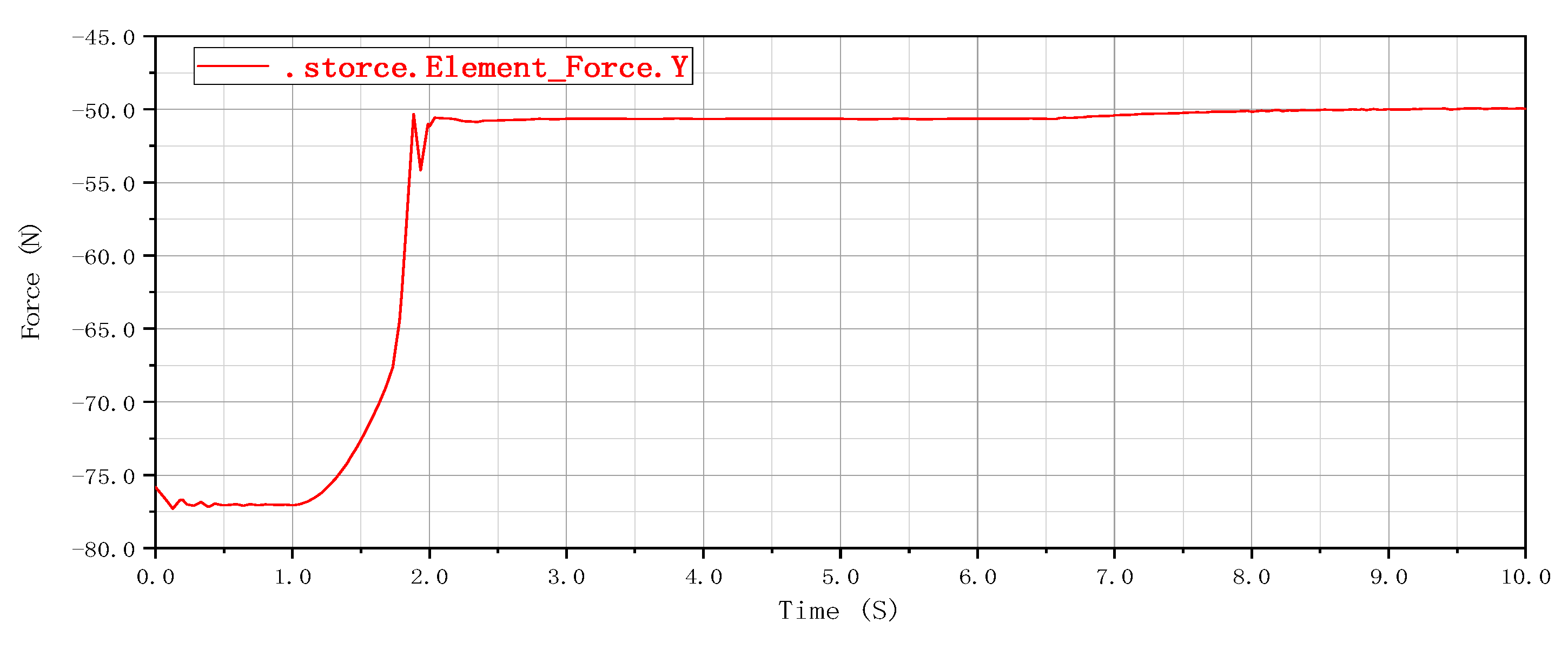
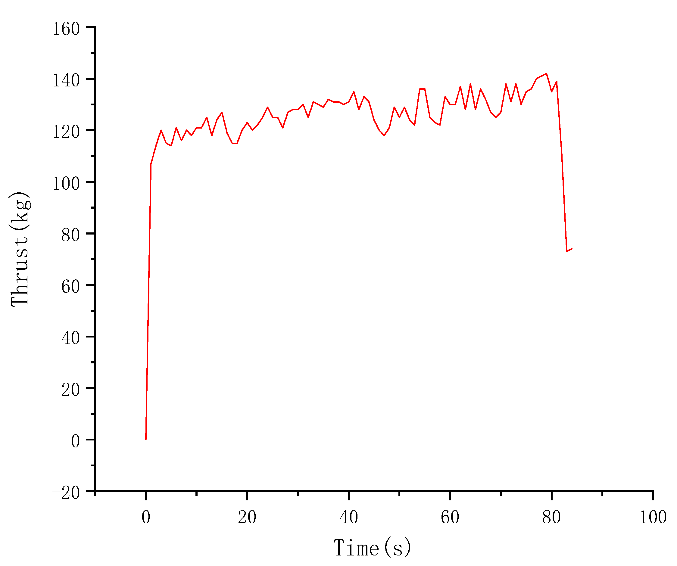
4.2. Horizontal Insertion Test When the Grouting Gun Enters the Soil
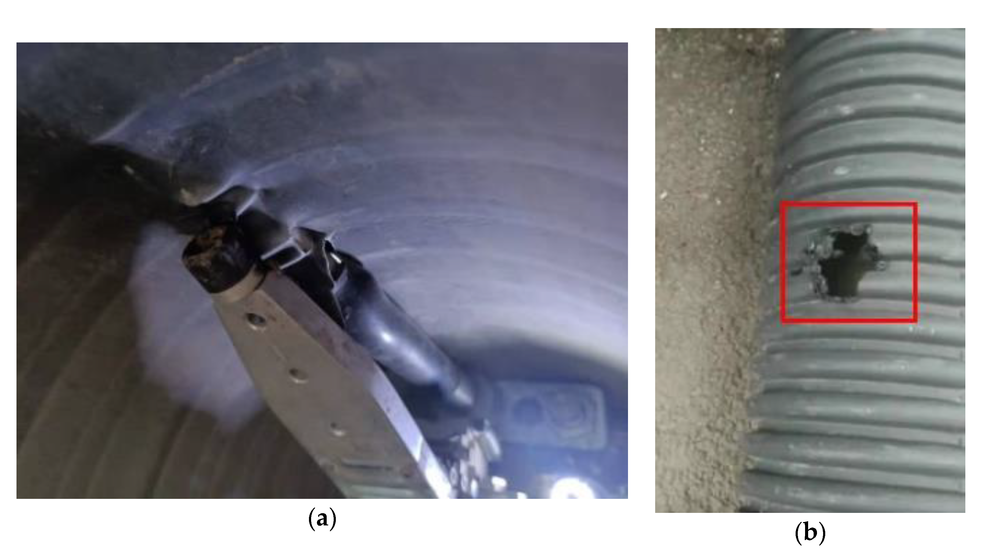
4.3. Hot-Melt Test of the Pipeline Grouting Robot
5. Conclusions
- (1)
- A new internal grouting and shaping process for pipelines is proposed, which is suitable for repairing the internal collapse in HDPE double-walled corrugated pipelines. The design requirements and indexes of the pipeline grouting robot are presented. Grouting can be performed in HDPE double-walled corrugated pipelines with inner diameters of 300 mm to 600 mm and can be positioned in different areas of the collapse. This robot can penetrate the wall of the HDPE double-walled bellows since it can move on its own power.
- (2)
- The overall scheme of the pipeline grouting robot is determined. It consists primarily of hot-melt, deflection, lifting, support, monitoring, and driving mechanisms. A mechanical analysis of the grouting, deflection, lifting, support, and travel processes is performed. Furthermore, the calculation formula of the thrust required for the grouting gun to penetrate the soil is determined while experimental verification is conducted.
- (3)
- The kinematics simulation of the grouting robot is performed using the ADAMS software, confirming that the thrust of the hydraulic lifting cylinder and the supporting hydraulic rod meets the requirements and that the supporting mechanism of the grouting robot can ensure the stability of the equipment during grouting. The grouting robot designed in this paper has been well applied in practice to avoid the impact of excavation from the ground on traffic.
Author Contributions
Funding
Conflicts of Interest
References
- Tanwani, R.; Iseley, D.T. Tracking and Steering Systems in Trenchless Construction. J. Constr. Eng. Manag. Asce 1994, 120, 65–76. [Google Scholar] [CrossRef]
- Li, J.; Zhou, M.; Si, Y.; Li, J. Trenchless Repair Technology and Application of Urban Sewer System. In Proceedings of the 2nd International Conference on Mechanical Engineering, Materials Science and Civil Engineering (ICMEMSCE 2013), Beijing, China, 25–26 October 2013; p. 992. [Google Scholar]
- Zhang, W.; An, G.; Zhou, L.; Liang, H. Application of Spraying Trenchless Repair Method for Drainage Pipeline. Geol. Sci. Technol. Inf. 2016, 35, 95–99. [Google Scholar] [CrossRef]
- Kim, J.H.; Ho, B.C. A study on the Development Plan for Trenchless Technology of Water Pipeline in Korea. J. Korean Soc. Water Sci. Technol. 2017, 25, 3–20. [Google Scholar]
- Lu, H.; Matthews, J.; Iseley, T. How does trenchless technology make pipeline construction greener? A comprehensive carbon footprint and energy consumption analysis. J. Clean. Prod. 2020, 261, 121215. [Google Scholar] [CrossRef]
- Zhao, Y.; Ma, B.; Ariaratnam, S.T.; Zeng, C.; Yan, X.; Wang, F.; Wang, T.; Zhu, Z.; He, C.; Shi, G.; et al. Structural performance of damaged rigid pipe rehabilitated by centrifugal spray on mortar liner. Tunn. Undergr. Space Technol. 2021, 116, 104117. [Google Scholar] [CrossRef]
- Zhou, Y.; Jiang, S.; Xie, M.; Zhao, X.; Sun, Z. Application of Trenchless Repair Technology in Urban Drainage Pipeline Maintenance. China Water Wastewater 2020, 36, 58–62. [Google Scholar]
- Li, J.; Zhang, J.; Chen, S. Study on dynamic viscoelastic properties and constitutive model of non-water reacted polyurethane grouting materials. Measurement 2021, 176, 109115. [Google Scholar] [CrossRef]
- Xu, J.-G.; Chen, Z.-H.; Wang, R. Mechanical Characteristic Analysis of Buried Drainage Pipes after Polymer Grouting Trenchless Rehabilitation. Adv. Civ. Eng. 2021, 2021, 14. [Google Scholar] [CrossRef]
- Liu, G.; Sun, Y.; Liu, J. Application of FRP Pipe in Trenchless Repair of Large Diameter Sewage Pipe. China Water Wastewater 2021, 37, 89–93. [Google Scholar]
- Ogden, M.W. Coating quality assurance for trenchless steel pipeline installations. Mater. Perform. 2004, 43, 32–34. [Google Scholar]
- Zare, M.R.; Iseley, D.T.; Najafi, M. Trenchless Limitations on Postearthquake Repair and Rehabilitation of Unpressurized Networks: Christchurch, New Zealand. J. Pipeline Syst. Eng. Pract. 2019, 10, 05019002. [Google Scholar] [CrossRef]
- Xie, M.; Zheng, T.; Yu, F.; Shen, L. Application of Trenchless Repair Technology for Siping Road Drainage Pipeline Repair Project in Shanghai. Environ. Eng. 2020, 38, 45–48. [Google Scholar]
- Chin, W.S.; Kwon, J.W.; Lee, D.G. Trenchless repairing of underground pipes using RTM based on the axiomatic design method. J. Compos. Mater. 2003, 37, 1109–1126. [Google Scholar] [CrossRef]
- Fang, H.; Li, B.; Wang, F.; Wang, Y.; Cui, C. The mechanical behaviour of drainage pipeline under traffic load before and after polymer grouting trenchless repairing. Tunn. Undergr. Space Technol. 2018, 74, 185–194. [Google Scholar] [CrossRef]
- Wang, R.; Wang, F.; Xu, J.; Zhong, Y.; Li, S. Full-scale experimental study of the dynamic performance of buried drainage pipes under polymer grouting trenchless rehabilitation. Ocean. Eng. 2019, 181, 121–133. [Google Scholar] [CrossRef]
- Lin, Z.; Guo, C.; Cao, D.; Ni, P.; Wang, F. An experimental study on the cutting failure of polymer grouting. Constr. Build. Mater. 2020, 258, 119582. [Google Scholar]
- Gil, L.D.; Chen, Y.; Quan, Z.; Liu, A. Trenchless Repairing Reinforcing Process of Underground Pipes with Advanced Composite Materials. Compos. Res. 2002, 15, 21–31. [Google Scholar]
- Orlov, V.A.; Orlov, E.V.; Zverev, P.V. Technologies for sectional trenchless repair of water discharge pipelines, Vestnik MGSU. Proc. Mosc. State Univ. Civ. Eng. 2013, 7, 86–95. [Google Scholar]
- Zhong, Z.; Bouziou, D.; Wham, B.; Filiatrault, A.; Aref, A.; O’Rourke, T.D.; Stewart, H.E. Seismic Testing of Critical Lifelines Rehabilitated with Cured in Place Pipeline Lining Technology. J. Earthq. Eng. 2014, 18, 964–985. [Google Scholar] [CrossRef]
- Ji, H.W.; Koo, D.D.; Kang, J.-H. Short- and Long-Term Structural Characterization of Cured-in-Place Pipe Liner with Reinforced Glass Fiber Material. Int. J. Environ. Res. Public Health 2020, 17, 2073. [Google Scholar] [CrossRef] [Green Version]
- Nuruddin, M.; DeCocker, K.; Sendesi, S.M.T.; Whelton, A.J.; Youngblood, J.P.; Howarter, J.A. Influence of aggressive environmental aging on mechanical and thermo-mechanical properties of Ultra Violet (UV) Cured in Place Pipe liners. J. Compos. Mater. 2020, 54, 3365–3379. [Google Scholar] [CrossRef]
- Fang, H.; Yang, K.; Li, B.; He, H.; Xue, B. Parameter Analysis of Wall Thickness of Cured-in-Place Pipe Linings for Semistructured Rehabilitation of Concrete Drainage Pipe. Math. Probl. Eng. 2020, 2020, 16. [Google Scholar] [CrossRef]
- Li, B.; Wang, F.; Fang, H.; Yang, K.; Zhang, X.; Ji, Y. Experimental and numerical study on polymer grouting pretreatment technology in void and corroded concrete pipes. Tunn. Undergr. Space Technol. 2021, 113, 103842. [Google Scholar] [CrossRef]
- Primin, O.G.; Pavlinova, I.I. Efficiency Of Pipe-Lines Rehabilitation By Method Of Applying Cement-Sand Coating. Promyshlennoe i Grazhdanskoe Stroitel’stvo 2020, 3, 58–62. [Google Scholar]
- Lu, H.; Wu, X.; Ni, H.; Azimi, M.; Yan, X.; Niu, Y. Stress analysis of urban gas pipeline repaired by inserted hose lining method. Compos. Part B Eng. 2020, 183, 107657. [Google Scholar] [CrossRef]
- Liu, R.; Liu, W.; Hong, Z.; Wang, L. A soil resistance model for subsea pipeline global lateral buckling analysis. Rock Soil Mech. 2015, 36, 2433–2441. [Google Scholar]
- Robbins, D.H.; Johnson, C.E.; Schafer, R.L.; Way, T.R. Modeling Soil-metal Sliding Resistance. Trans. Asabe 2021, 64, 435–446. [Google Scholar] [CrossRef]


| Pipe Inner Diameter (mm) | Maximum Upward Lifting Angle of Grouting Gun Body |
|---|---|
| 300 | 5° |
| 400 | 11° |
| 500 | 16° |
| 600 | 22° |
| Project | Parameter |
|---|---|
| Quality control of in-pipe grouting robot (M1) | 300 kg |
| Mass of 50 m drag pipe (M2) | 100 kg |
| Travel speed (v) | 0.5 m/s |
| Acceleration (a) | 0.2 m/s2 |
| Gravitational acceleration (g) | 9.8 m/s2 |
| Wheel radius (r) | 0.05 m |
| Name | Poisson’s Ratio | Modulus of Elasticity (MPa) | Density (kg/m3) |
|---|---|---|---|
| Rubber | 0.45 | 1 × 10⁻² | 9.6 × 10² |
| 35 Steel | 0.29 | 2.05 × 10⁵ | 7.85 × 10³ |
| 304 Stainless steel | 0.29 | 1.9 × 10⁵ | 8 × 10³ |
| Parameter Name | Value |
|---|---|
| Static friction coefficient | 0.5 |
| Dynamic friction coefficient | 0.43 |
| Static translation speed (mm/s) | 0.1 |
| Friction translation speed (mm/s) | 10.0 |
Publisher’s Note: MDPI stays neutral with regard to jurisdictional claims in published maps and institutional affiliations. |
© 2022 by the authors. Licensee MDPI, Basel, Switzerland. This article is an open access article distributed under the terms and conditions of the Creative Commons Attribution (CC BY) license (https://creativecommons.org/licenses/by/4.0/).
Share and Cite
Li, Y.; Xu, J.; Nan, F.; Su, H.; Zhao, T. Dynamic Simulation and Experimental Study of the HDPE Double-Walled Corrugated Pipe Grouting Robot. Sustainability 2022, 14, 6776. https://doi.org/10.3390/su14116776
Li Y, Xu J, Nan F, Su H, Zhao T. Dynamic Simulation and Experimental Study of the HDPE Double-Walled Corrugated Pipe Grouting Robot. Sustainability. 2022; 14(11):6776. https://doi.org/10.3390/su14116776
Chicago/Turabian StyleLi, Yufang, Jiyang Xu, Feng Nan, Hongli Su, and Tongxu Zhao. 2022. "Dynamic Simulation and Experimental Study of the HDPE Double-Walled Corrugated Pipe Grouting Robot" Sustainability 14, no. 11: 6776. https://doi.org/10.3390/su14116776
APA StyleLi, Y., Xu, J., Nan, F., Su, H., & Zhao, T. (2022). Dynamic Simulation and Experimental Study of the HDPE Double-Walled Corrugated Pipe Grouting Robot. Sustainability, 14(11), 6776. https://doi.org/10.3390/su14116776