Abstract
In this study, we utilize the advantages of offshore wind power resources in coastal areas to make up for the shortage of freshwater. At the same time, freshwater can be used as raw material to supply hydrogen energy. An operation strategy considering power and water input for an electrolyzer is proposed and an electrolyzer variable efficiency model under optimal operation mode is also proposed. Considering both energy benefits and operation and maintenance costs, this paper sets up the wind–hydrogen–water power grid system optimal operation model. Simulation analysis is carried out from the aspects of economy, accommodation, uncertainty of impacts of the reservoir capacity, water satisfaction, and so on. The results show that the accommodation rate reaches 98.2% when considering the proposed operation strategy. The average daily operating cost of the system reaches USD 3.9 × 10⁴, and the strategy and model have good economic benefits and practical significance.
1. Introduction
Although the growth rate of global energy demand will slow down in the next 30 years, China will still be the world’s largest energy consumer. The energy demand growth will come entirely from emerging economies, which will account for more than 20% of global energy accommodation in 2050 under the three scenarios of rapid transition, net zero, and business as usual [1]. China has stated that its carbon emissions should strive to reach the peak before 2030 and strive to achieve carbon neutrality before 2060. The strong growth of renewable energy, represented by OWP (more stable, less variable, higher utilization rate, higher capacity coefficient, and more widely accepted by society), will become a key driver of China’s energy transition, leading the transition to low-carbon energy. As a recognized clean energy, hydrogen energy will also play an increasingly important role in the future energy system due to its advantages of being pollution-free, permitting diverse utilization, inducing low losses, high utilization rates, and allowing convenient transportation.
Coastal areas are rich in resources, most of which come from offshore wind power, and offshore wind power does not occupy land area and has no shelter. It has a greater load and higher energy density than onshore wind power, which is the resource advantage of coastal areas. During the “14th Five-Year Plan” period, China’s OWP will continue to develop rapidly, and the installed capacity is expected to reach 10 MW, which is 2.4 times that of the “13th Five-Year Plan” period [2,3,4,5]. At the same time, the resource disadvantage of coastal areas comes from the shortage of freshwater resources. With the rapid growth of the national population and economy, the growth rates are about 5.5% and 8.9% [6,7,8,9]. The shortage of freshwater is becoming more and more serious. Therefore, in order to avoid resource disadvantage by advancing resource advantages, coastal areas use seawater desalination systems to absorb the enrichment of offshore wind power, and the desalinated water can also supply hydrogen energy for operation. The scale of desalination has developed rapidly. By the end of 2018, China had built 142 desalination plants, with a total output of 1.202 million tonnes per day [6], and the cost of freshwater has been effectively reduced. Thus far, it is about 5.99 USD/t, as shown in Figure 1. This will have a profound impact on the sustainable development of China’s WHW-PGS business.
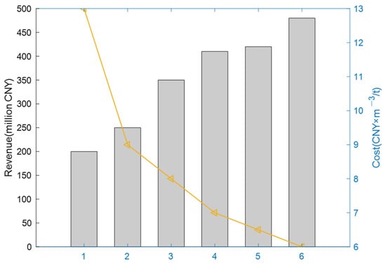
Figure 1.
Annual changes in China’s desalination budget.
Some papers have begun to study the optimal scheduling of desalination loads and optimal configurations. Prathapaneni et al. [10] proposed a new method for designing a microgrid with a reverse osmosis seawater desalination system and to ensure the optimal and flexible operation of desalination loads and microgrid power dispatching. Karavas et al. [11] proposed different configuration models of five photovoltaic powered seawater desalination systems and determineed that the configuration structure of seawater desalination systems generated by photovoltaic power generation, including water storage, small capacity battery pack, and energy management system is the most economical and technically feasible. Abdelshafy et al. [12] proposed a grid of connected multi-renewable energy and seawater desalination integrated systems to determine the economic benefits of providing freshwater to the community and to verify that desalination powered from PV/wind/BSS/diesel is the optimal system. Liu et al. [13] proposed an optimal planning of a coastal hybrid renewable energy system by considering the virtual energy storage of desalination and explored the impact of freshwater virtual energy storage characteristics on the system. Zhou et al. [14] proposed a multi-objective power grid optimal operation system with seawater desalination load solved by NSGA-III to verify the effectiveness of the model. However, these studies are more focused on the optimal operation of a power grid and lack research on the comprehensive utilization of freshwater resources.
In terms of offshore wind power accommodation, Liu et al. [15] proposed a technology–energy–economy hybrid power system model powered by offshore wind power to guide the subsidy regulation of system stability and economy. Dakic et al. [16] proposed an optimization model for a low-frequency AC offshore wind power transmission system by considering cost sensitivity in order to guide future offshore wind power transmission technology. Wu et al. [17] proposed an optimal location selection including offshore wind Power Photovoltaic-Pumped storage to make up for the lack of renewable energy research. However, the literature focuses on the use of new energy technology and source-network load-storage operations to absorb offshore wind power load and there is a lack of attention and focus directed toward the resource characteristics of coastal areas; the idea of the current research study compensates the disadvantage of freshwater resources with the advantages of offshore wind power resources.
With the rapid development of green hydrogen energy, much literature includes research on power grid interaction with hydrogen energy. Zhang et al. [18] proposed an electric–hydrogen energy system based on P2G technology to conduct optimal operations with the goal of reducing energy costs and improving system reliability and quantifying the level of renewable energy by considering the wind curtailment rate. Xiao et al. [19] proposed an optimal operation strategy of wind electrolysis HES participating in the electricity market and hydrogen market trading by considering CVaR with the goal of profit maximization and achieving flexibility and economy. Beyrami et al. [20] proposed an optimal operation of a single-effect seawater desalination unit combined with a fuel cell. From the three perspectives of economy, environment, and external environment, thereobjectives (maximum efficiency, minimum total cost rate, and minimum carbon dioxide emission rate) were analyzed for multi-objective optimization, which was solved by a genetic algorithm to verify the feasibility of the model. However, these studies focus on the optimal operation of a power grid containing hydrogen energy and do not consider the source of electrolytic raw materials of an electrolyzer or the control strategy of a load.
Based on the above issues, the main contributions of this paper are summarized as follows:
- (1)
- Considering both the energy accommodation and freshwater input for electrolyzation, which are regarded as the energy input and raw material input of the system, this paper formulates a joint-operation power control strategy, establishing a wind–hydrogen–water power grid system to improve offshore wind power accommodation rate, freshwater production, and energy utilization rate;
- (2)
- The electrolyzer variable efficiency model is introduced to make full use of the flexible adjustment characteristics of the electrolyzer as a kind of detailed controllable load to match wind power fluctuations and to improve the system economy and reality;
- (3)
- In view of the problem of operation restriction arising from the direct connection between desalination and electrolysis, reservoir regulation is considered to reveal the uncertainty impacts of the reservoir capacity.
The remainder of this paper is organized as follows. Section 2 introduces the WHW-PGS architecture and proposes the mathematical model of the system. Section 3 proposes JO-PCS, and Section 4 proposes the optimal operation model. The case studies are delivered in Section 5. Finally, Section 6 concludes the paper.
2. WHW-PGS Architecture and Mathematical Model
This paper studies WHW-PGS at a regional level. With OWP and hydrogen as energy carriers, it runs through the entire system’s development, storage, transmission, and distribution and uses links while aiming to accommodate offshore wind power on a large scale, to meet the freshwater and electrical energy needs of coastal users in production and living, and to achieve 100% green energy supply. The system architecture is shown in Figure 2.

Figure 2.
WHW-PGS.
In the system energy input link, offshore wind turbines are connected to onshore AC buses through power transmission and AC-DC-AC converters to provide electrical energy to the entire system. Part of the electrical energy is sent to the desalination system to desalinate seawater, and freshwater is stored in a reservoir for backup. When there is too much OWP and it meets the supply of freshwater, the electrolyzer can consume excess electrical energy in hydrogen storage tanks by electrolyzing freshwater to produce hydrogen. Excess hydrogen can also be traded with the hydrogen market to obtain a part of the income, and water comes from excess high-purity freshwater in the reservoir, which can greatly improve the efficiency of electrolysis. When OWP is insufficient and cannot meet the freshwater supply, the stored hydrogen can be converted into electrical energy through the fuel cell to supplement the power shortage of the system. At the same time, the transformer interacts with the public distribution network to supplement the power imbalance and to realize the safe and stable operation of WHW-PGS.
In addition to electricity, hydrogen is a clean and environment-friendly secondary energy source. From the perspective of the economy, the operation and investment costs of EHP are fixed, and the main factor affecting the system income is the power source consumed. From the aspect of system efficiency analysis, the maximum efficiency of wind EHP lies in the choice of core equipment. Currently, alkaline water electrolysis (ALK), proton exchange membrane electrolysis (PEM), and solid oxide electrolysis (SOEC) are widely used, and the comparison of their technologies is shown in Table 1.

Table 1.
Comparison of three electrolyzed water technologies.
From the perspective of application scenarios, efficiency improvement, and cost reduction, HES is modeled and analyzed by PEM as an example. The electrolysis principle is shown in Figure 3.

Figure 3.
Electrolysis principle.
The electrolysis process, anode reaction, and cathodic reaction are described as follows.
2.1. HES Mathematical Model
In this paper, storages related to power, water, and hydrogen are neglected. It is assumed that desalinated water and generated hydrogen are consumed immediately by the users or the next process, and storage is regarded to be enough and secure for the entire system to realize energy regulation.
(1) Electrolyzer mathematical model: Compared with the direct electrolysis of seawater, the electrolysis of freshwater can improve the electrolysis efficiency of the system. The power consumed, moles of hydrogen produced, and the quality of hydrogen produced are as follows [21].
(2) Fuel cell mathematical model: The response time is fast and the operation power is stable. From a certain degree of cleanliness, fuel cells can replace diesel power generation equipment. Power consumed by the redox process, moles of hydrogen consumed, and the quality of hydrogen consumed are as follows [21].
(3) HST mathematical model: EHP is processed by the compressor and stored in HST. At the same time, HET can provide a scheduling and time-shifting hydrogen sources for the system. Taking into account that it is regarded as an adiabatic expansion, according to the ideal gas equation of state, the dynamic equation of the hydrogen volume change is described as follows.
2.2. Desalination Mathematical Model
The desalination system, shown in Figure 4, mainly considers its freshwater production and the change of reservoir volume. The desalination load is a controllable load. The freshwater production and the water storage capacities of the reservoir are described as follows [22].

Figure 4.
Desalination system.
3. Optimal Operation Strategy of HES and Desalination
Each part of the system can be regarded as a controllable unit, and a feasible power control strategy for the joint operation of a wind power hydrogen production system and seawater desalination system is proposed.
3.1. Operation Rules
The control strategy must follow certain operating rules: (1) mainly for carbon-free, large-scale accommodation of OWP; (2) hydrogen cannot exceed its safe operating power and cannot exceed its specified margin; (3) the priority order of system control rules is as follows: desalination > HES > distribution network.
3.2. Operation Strategy
(1) Control strategy of desalination system: The desalination load can be controllable, while the reservoir plays a regulatory role. If the desalination link is directly connected with the electrolysis link, the latter will seriously restrict the operation time and range of the former, which will lead to low system operation efficiency, and a serious situation will affect the coastal users’ water satisfaction. A reservoir of a certain capacity between the two links can relieve the above restrictions. According to the preparation of freshwater first stored in the reservoir, the first supply is the residential water load, and excess freshwater is in the order to supply EHP. Part decoupling between seawater desalination and water electrolysis is realized by using the regulating capacity of water storage and effluent of the reservoir.
is adjusted according to full load operation. According to , there is a lower limit of the desalination load and it can be adjusted in the following manner.
① As shown in Formula (15), the current storage capacity is sufficient to supply the water load of residents, and the desalination device does not need to be activated.
② As shown in Formula (16), water is insufficient. It is necessary to start the desalination device.
The minimum number of the operating desalination devices is defined in (17), and the operating power is defined in (18).
Considering that excess freshwater will deteriorate the next day and electrolytic fresh water can improve EHP efficiency, excess freshwater is passed into the electrolysis process.
(2) Control strategy of HES: According to the of HES, the rated load limit of the charging electrolyzer, and fuel cell discharge, the upper and lower limits of the HES load per hour can be calculated to determine the adjustable range of HES.
(3) JO-PCS: Firstly, initialize the parameters of each equipment and the load of electricity and fresh water for 24 h a day. Secondly, calculate the upper and lower limits of desalination load. Finally, adjust power according to the joint operation power control strategy, which is shown in Table 2. “√” means minimum power purchase cost, “×” means minimum load shedding cost in Table 2.

Table 2.
Joint operation power control strategy.
is the normal load at time t; is OWP; is defined as the net load of the system at time t as follows.
The specific two-tier strategy is given in detail below.
(1) As shown in Formula (24), the electrical energy generated by renewable energy can fully supply the seawater desalination device to meet the water demand of residents.
Redundant electric energy is consumed by HES, and the electrolyzer starts and the reserve electrical energy is described in (25), where is the electrolyzer’s efficiency.
The freshwater for EHP is taken from the reservoir, and it is prepared in this state and is first stored in the reservoir.
(2) As shown in Formula (27), the freshwater output in this state is (28).
The redundant electrical energy is not sufficient for switching on another desalination device. Thus, it is absorbed by HES.
① When it is as described in (30), the electrolyzer can absorb part of the redundant electrical energy and sell the excess to the grid to obtain part of the income.
② When it is as described in (31), the electrolyzer can completely dissipate redundant electrical energy without interacting with the grid.
(3) When it is as described in (32), the freshwater output is as defined in (33).
At this time, shortfall is supplied by the fuel cell to keep the desalination unit running at minimum power, where is the fuel cell’s efficiency.
(4) When it is as described in (35), the system’s power is insufficient to supply the conventional load.
The desalination device does not work, and the fuel cell is switched on for discharge.
① When it is as described in (37), the shortage of power can be fully replenished by HES without interacting with the grid;
② When it is as described in (38), the shortage of power cannot be fully replenished by HES, the fuel cell operates at the maximum discharge power, and the load shedding cost and power purchase cost are compared to determine whether the shortage is supplied by the grid.
4. Optimal Operation Model of WHW-HS
Defining the system’s average daily energy accommodation revenue and daily average operation and maintenance cost and taking into account the system operation and maintenance cost and revenue return, this paper establishes an optimal operation model.
4.1. Objective Function
This paper aims to minimize the average daily operating cost of the system.
(1) takes into account the shortfall load cost and income return. Moreover, income return takes into account three parts of electricity sales, hydrogen sales, and freshwater sales income. According to Section 3.2, the power purchase cost or load shedding cost are selected for shortfall load costs, and the power purchase cost and load shedding cost cannot coexist.
(2) : Hydrogen production from wind energy is competitive in the game with higher-level power grids. Thus, this paper assumes that the cost of wind power generation is free. Therefore, only a desalination system, electrolyzer, and fuel cell are considered.
4.2. Constraints
(1) Power balance constraint: The total power generation of the entire system (offshore wind power and fuel cell) is equal to the total power consumption (electrolytic cell, desalination, conventional load, and grid interaction). Moreover, the electrolytic cell and fuel cell in HES cannot work at the same time; when one of them works, the variable is 1 and the other is 0.
(2) Wind energy output constraints: OWP cannot exceed its maximum output power . At the same time, should also meet the conditions.
(3) Desalination system constraints: The output of the desalination system must fluctuate between its upper and lower limits.
(4) HES constraints: By comparing batteries, the battery capacity at time t is related to the battery capacity, operating power, and efficiency at the previous time. can be defined as follows.
Moreover, there is a certain margin constraint on battery capacity and SOC, and they cannot exceed the upper limit and cannot be lower than the lower limit.
The operating power of the electrolyzer and fuel cell is greater than its safe operating power and less than its upper limit.
(5) Distribution grid constraints: In order to ensure the stable operation of the power grid, its operating power shall not exceed the following limit.
5. Case Studies
The microgrid in a coastal area in southern China is selected as an example. It is assumed that the installed capacity of offshore wind power is 750 MW, and the maximum water load in this area is 356 × 104 tons. According to the parameter changes in the area, the simulation step is defined as 1h and the period is 24 h, which is solved by the CPLEX solver in MATLAB. The algorithm is the default interior point method, and the operation time is 2.84 s. The processor of the computer is Intel(R) Core(TM) i5-10210U CPU at 1.60 GHz 2.11 GHz and RAM is 8 G.
5.1. Analysis of the Impact of Different Operation Modes on the Plan
Since different operating modes have different effects on the operating characteristics and economy of the system, we explore the importance of HES relative to OWP accommodation and the feasibility of JO-PCS under the condition of a certain efficiency of the electrolyzer. This paper adopts four operating cases, which are shown in Table 3. The four operation cases selected in this paper can well support our innovation. A1 is used to verify the support of offshore wind power resources and the avoidance of the lack of fresh water resources. A2 is used to support the innovation of hydrogen electrolysis raw materials from fresh water. The comparison between A3 and A4 can verifies the effectiveness of the proposed strategy, as well as the economy and consumption characteristics of the model. Considering the shortage of freshwater resources for users in coastal areas, the user’s water satisfaction index is introduced to evaluate the plan.

Table 3.
Four operating modes.
(1) The economic impact of different operation model on the plan: The results of different economic optimal operations are shown in Table 4.

Table 4.
Economic optimization operation situations.
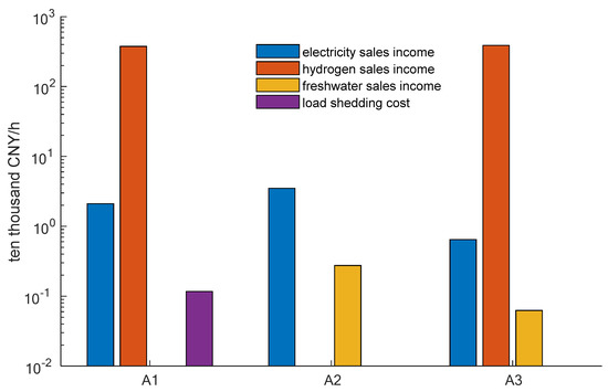
Figure 5.
of each part.

Figure 6.
of each part.
As A4 did not participate in regulation and, during the entire operation process, the seawater desalination system and the electrolyzer were operated at a constant power, the fuel cell did not participate in the work, the entire system’s operation was in an unsatisfactory state, the economic benefits were poor, and the average daily operating cost exceeded 311 × 104 × USD/h, which is not meaningful compared to the economic benefits under the operating strategy proposed in this paper, Thus this part will not be discussed. The income from the water sales of A3 increased by 3.2% compared with that of A1, and the income from electricity sales of A3 decreased by about 3 times. The main reason is that when the desalination system is operating alone, and redundant wind energy is not fully accommodated. A3’s hydrogen sales revenue is lower than that of A2. Although it improves the economics of the system’s green and low-carbon operation, the lack of freshwater revenue leads to a decrease in the total system’s energy revenue.
On the whole, A1 has a load shedding cost of 4354 USD, while the load shedding costs of A2 and A3 systems are 0, indicating that HES is effective for redundant wind energy accommodation. The of A3 is the smallest, reaching 37,475.5 USD/h, which is about 10 times lower than the previous two methods. Although is better than that of A2, a substantial increase compared to A1 occurs mainly due to the high equipment cost. However, when considering JO-PCS, it not only meets water demand but also reduces . In the future, while taking into account the green, low-carbon, reliable, and economic operation of the system, focusing on key equipment technology and reducing equipment costs will help improve strategic competitiveness.
(2) Impact on plan operating characteristics: We consider OWP , normal load , desalination load , HES load , grid interaction load , and total tie line load .
The operating results are shown in Figure 7, Figure 8, Figure 9, Figure 10, Figure 11 and Figure 12.

Figure 7.
Operation power at A1.

Figure 8.
Hydrogen production at A2.
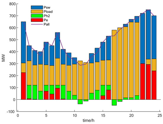
Figure 9.
Operation power at A2.

Figure 10.
Operation power at A3.
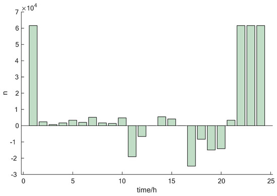
Figure 11.
Hydrogen production at A3.

Figure 12.
Operation power at A4.
The average accommodation rate is shown in Table 5.

Table 5.
Average accommodation rate.
Wind curtailment is shown in Figure 13.

Figure 13.
Wind curtailment situation at A1.
In this paper, not only the average curtailment volume but also the curtailment rate at each moment will be studied, which not only serves as a reference for the accommodation in A1 case, but it also paves the way for the future study of real-time curtailment scheduling guidance.
The comprehensive analysis shows that there is a gap between and under A1 and A2. It fluctuates around 400 MW from 22 h to 10 h the next day under A2. The energy accommodation effect under A4 is poor. The desalination device and the electrolyzer device are not running at the maximum power. The fuel cell is not switched on, and the system power balance cannot be guaranteed. When a single device is running, OWP cannot be accommodated well, and the utilization rate of renewable energy is low.
When considering JO-PCS, and energy accommodation rate reaching 98.2% are the highest. The OWP accommodation rate is maintained at about 99% for more than 95% of the day, and the regulation effect is the best. From 1 h to 10 h, OWP’s output is sufficient and the residential electricity load is small. The desalination device is added to produce freshwater, and excess power is used to produce hydrogen. The desalination plant had the first peak of working power, namely 200 MW, and the first peak of hydrogen production, and at the same time, redundant power is sold to the grid. The first peak of electricity accommodation occurred at 11 h. The desalination device is removed, and residents fetch water from the reservoir. Hydrogen accommodation increases, and the fuel cell begins to work to fill the shortage. From 21 h to 24 h, the output power of OWP increases and reaches the maximum value at 23 h, which is 750 MW, and the desalination unit is also working at its peak.
We introduce the curtailment rate at each moment to analyze the operation plan.
We assume that the deviation between freshwater supply and water load is quantified to define the evaluation index of user water satisfaction.
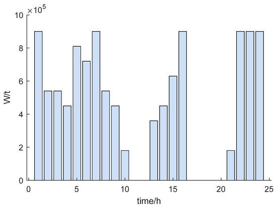
Figure 14.
Freshwater production at A1.
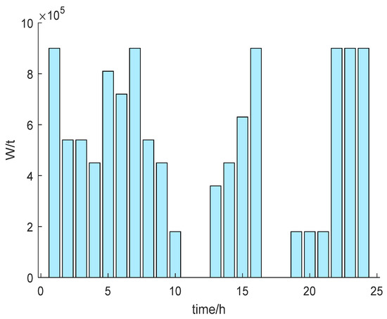
Figure 15.
Freshwater production at A3.
(3) It can be observed that the system increases freshwater production during periods of sufficient wind at night and infrequent user activities and peak water accommodation. Compared with A3, the freshwater output of A1 is 0 at 19 h and 20 h, which lowers the overall USE-WU. Taking full account of JO-PCS, the average water satisfaction of the area is as high as 94.44%, and 22 h–1 h is the highest.
The first part of the simulation in this section mainly realizes the economic benefits of WHW-PGS; the second part mainly realizes the superiority of JO-PCS; the third part mainly realizes the sufficient supply of freshwater and the improvement of USE-WU.
5.2. Analysis of the Influence of Changes in the Efficiency of Electrolyzer
When the input power of the electrolyzer reaches a certain point, it is better to consider the hydrogen production monomer of the electrolyzer alone. However, this study not only pursues the best monomer economy but also focuses on the overall economics of the microgrid. It should follow the load demand and OWP output to show dynamic changes. can be expressed as the ratio of the calorific value of EHP to the total calorific value of the system [22].
Combining (4), (5), and (39), efficiency —input power curve—characteristics are shown in Figure 16. Different variable efficiency operation modes become B1, B2, and B3.

Figure 16.
characteristics.
Draw the realistic operation curve according to the realistic data [22]. The fitting curve is fitted as a quadratic function by the least square method. Figure 16 shows that increases with an increase in , and the maximum value hovers between 0.6 and 0.7. When starts to increase, increases obviously. When gradually approaches its rated power, has a decreasing trend, slowing down to about 0.7. However, its hydrogen production increased. In order to facilitate the solution, this paper uses a fitted quadratic function to express its curve characteristic state. Moreover, at B3 and A3 is shown in Figure 17.

Figure 17.
at B3 and A3.
Figure 17 shows that the HES output under B3 is slightly smaller than that of A3, which has no significant impact on the energy accommodation of OWP and avoids the waste and loss of the electrolyzer working at maximum efficiency. The overall efficiency of B3 varies from 0 to 0.7. In particular, at 7 o’clock, the electrolyzer reaches its maximum efficiency of 0.6. At this time, the input power of the electrolyzer reaches 25 MW, and its operating power reaches the maximum to absorb renewable energy. At this point, the efficiency of the electrolyzer is 0. The electrolyzer does not work, and the fuel cell works to supplement the system’s shortage, and the overall efficiency change is also in line with the efficiency-input power curve characteristics.
Figure 18 and Figure 19 show that is still fluctuating regularly between 0.1 and 0.6, and the maximum value remains at 0.67 at 22–24 o’clock.
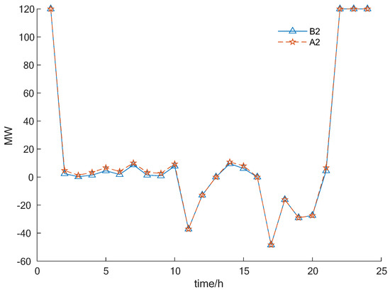
Figure 18.
Operation power at B2 and A2.

Figure 19.
at B2.
At this time, the input power of the electrolytic cell fluctuates between 25 and 35 MW, and the electrolytic cell reaches the maximum operating power. Starting at 11 o’clock, the system is lacking, the electrolytic cell stops working, and efficiency is at 0. Compared with B3, due to the lack of seawater desalination devices in the system to coordinate work, the overall efficiency is slightly greater than B3, which is in line with characteristics. The economic results of different operations are shown in the Table 6. As observed, the of B2 is 8.4% lower than that of A2, and the of B3 is 44.3% lower than that of A3, which are of good economic significance.

Table 6.
The economic results of different operations.
The simulation in this section mainly realizes the introduction of EVEM to improve economic and practical benefits and to provide full play to the flexible adjustment characteristics of the electrolyzer in order to match OWP fluctuations and ensure the reliability of electricity use.
5.3. Analysis of Uncertainty Influence of Reservoir Capacity
In order to explore the influence of the change of reservoir capacity on the regulation performance of WHW-MS, three adjustment methods were selected with reference to A3.
C1: Reservoir capacity increased by 10%;
C2: Reservoir capacity reduced by 5%;
C3: Reservoir capacity reduced by 10%.
The different economic results are shown in Table 6. The changes of and in are shown in Figure 20 and Figure 21. The energy accommodation rate is shown in Figure 22.

Figure 20.
Changes in .

Figure 21.
Changes in .

Figure 22.
The change of energy accommodation rate.
From Figure 20 and Figure 22, it can be obtained that of C3 increased by 80.1% and 32.7% compared with C2 and C1. The OWP accommodation rate for C3 is the largest, reaching 98.42%, while C1 is the smallest, reaching 97.54%. When the reservoir’s capacity decreases, decreases, and and increase. Meanwhile, the emergency freshwater supply of the system is insufficient, and the operating power of desalination increased. The operating power of the electrolyzer does not change at most times, while it slightly increases at other times, leading to an increase in the accommodation of renewable energy. At 22:00 and 23:00, the output of offshore wind power is large, which is similar to the change of the offshore wind power curve in Figure 10. At this time, a large amount of power is transmitted through the power grid, and the local energy utilization rate is reduced.
The simulation in this section mainly realizes the economic benefits and regulation benefits of the regulation and control reservoir and guarantees the safe and stable operation of the system.
6. Conclusions
Taking into account the parallel of blue offshore wind energy, blue fresh water energy and green hydrogen energy are of great economic significance for creating a carbon-free, safe, and stable microgrid system:
- (1)
- Introducing the “Coastal multi-energy complementation” optimal operation strategy (JO-PCS), which can flexibly adjust and match wind power fluctuations, achieving peak shaving and valley filling, greatly reduces interactions with the public grid and reduces the average daily operating cost of the system.
- (2)
- Aiming at the efficiency-power characteristics of the electrolyzer, the variable efficiency model of the electrolytic cell is introduced to improve the operation strategy, which can make the system more economic and practical and avoid resource loss caused by the improper use of system equipment.
- (3)
- When the reservoir drops, the emergency freshwater supply of the system is insufficient, resulting in an increase in the number of desalination devices. Although energy consumption increases, the cost also increases.
In future studies, we aim to research the following:
- (1)
- With the increase in OWP offshore deep-sea HVDC transmission projects and the reduction in the investment cost of HES, it can effectively increase the utilization rate of renewable energy and promote the prosperity and development of coastal microgrids.
- (2)
- The double objective optimization operation, which considers the relationship between operation cost and the overall system’s energy efficiency as well as the impact of hydrogen storage on the system, will be a part of future studies.
Author Contributions
Methodology, Z.L.; validation, Z.L., H.W. and B.Z.; investigation, H.W., Z.L. and B.Z.; data curation, D.Y.; writing—original draft preparation, Z.L., H.W. and B.Y.; writing—review and editing, H.W., G.L. and C.X.; supervision, D.Y. and B.H. All authors have read and agreed to the published version of the manuscript.
Funding
This work was partially supported by the National Natural Science Foundation of China (61703081), the Fundamental Research Funds for the Central Universities (N2104014), the Liaoning Revitalization Talents Program (XLYC1902090), the Guangdong Basic and Applied Basic Research Foundation (2021A1515110778), and the State Key Laboratory of Alternate Electrical Power System with Renewable Energy Sources (LAPS21007).
Institutional Review Board Statement
Not applicable.
Informed Consent Statement
Not applicable.
Data Availability Statement
The unprovided data used in this paper are confidential, which has not yet been published. The data are provided by the industrial partner, which is State Grid Liaoning Electric Power Co., Ltd.
Acknowledgments
The authors would like to acknowledge State Grid Liaoning Electric Power Co., Ltd. for providing confidential and unpublished data.
Conflicts of Interest
The authors declare no conflict of interest.
Nomenclature
| OWP | Offshore wind power |
| WHW-PGS | Wind–hydrogen–water power grid system |
| JO-PCS | Joint operation power control strategy |
| EVEM | Electrolyzer variable efficiency model |
| EHP | Electrolytic hydrogen production |
| HES | Hydrogen energy system |
| HST | Hydrogen storage tank |
| USE-WU | User satisfaction evaluation of water use |
| Performance parameter | |
| k | Impurities |
| SOC | State of charge |
| O | Rated capacity |
| Load | Conventional power consumption |
| a | Net |
| ov | Redundancy |
| sh | Defect |
| Cf | The average daily operating cost |
| Cu | Daily energy accommodation revenue |
| Cm | Daily average operation and maintenance cost |
| u | Unit price (accommodation) |
| m | Unit price (benefit) |
| ∆P | The climbing power |
| E | Battery capacity |
| Self-discharge coefficient | |
| S | User water satisfaction |
| Curtailment rate | |
| HHV | Calorific value of hydrogen |
| Q1 | External heat required for the electrolysis reaction |
| Q2 | Heat water to meet reaction heat |
| P | Electric power (MW) |
| W | Fresh water load in the reservoir (t) |
| N | Desalination’s Number |
| G | Freshwater production(t) |
| Y | Pressure |
| (t) | At time t |
| ez | Electrolyzer |
| fc | Full cell |
| x/w | Desalination |
| sw | Offshore wind power |
| e | Grid (1—forward, 2—opposite) |
| max | Upper limit |
| min | Lower limit |
| H2/H | Hydrogen |
| V | Certain voltage (Volt) |
| A | Whether the electrolytic cell is opened, run to take 1; otherwise take 0. |
| i | Electrolyzer’s number |
| F | Faraday constant |
| Faraday efficiency | |
| Efficiency | |
| T | Adiabatic temperature (K) |
| M | Quality of hydrogen (kg) |
| V | Volume (m3) |
| n | Moles of hydrogen |
| H2in | Input of hydrogen load |
| H2out | Output of hydrogen load |
| uw | Electrolytic water accommodation related to power accommodation |
| T1 | Temperature of the heated substance |
| T0 | Ambient temperature |
| user | Use |
References
- British Petroleum. Energy Outlook 2020 Edition; International Energy Agency: Paris, France, 2020. [Google Scholar]
- Anton, M.Z.G.; Chung, H.H.; Jui, C.L. Review of recent offshore wind power strategy in Taiwan: Onshore wind power comparison. Energy Strategy Rev. 2021, 38, 100747. [Google Scholar]
- Zheng, X.H.; Shi, C.X.; Wen, X.S. Review of factors affecting China’s offshore wind power industry. Renew. Sustain. Energy Rev. 2016, 56, 1372–1386. [Google Scholar]
- Qian, L.; Yan, S.; Mengcheng, W. Decision-making methodologies in offshore wind power investments: A review. J. Clean. Prod. 2021, 295, 126459. [Google Scholar]
- Kamal, J.R.G.L.; Fred, F.A. Structural dynamics of offshore Wind Turbines: A review. Ocean Eng. 2022, 251, 111136. [Google Scholar]
- Lin, S.; Zhao, H.; Zhu, L. Seawater desalination technology and engineering in China: A review. Desalination 2021, 498, 46–59. [Google Scholar] [CrossRef]
- National Development and Reform Commission and the State Oceanic Administration. The 13th Five-Year Plan for Nation; Seawater Utilization; National Development and Reform Commission: Beijing, China, 2016.
- Zheng, X.; Chen, D.; Wang, Q.; Zhang, Z. Seawater desalination in China: Retrospect and prospect. Chem. Eng. J. 2014, 242, 404–413. [Google Scholar] [CrossRef]
- Gong, S.; Wang, H.; Zhu, Z.; Bai, Q.; Wang, C. Comprehensive utilization of seawater in China: A description of the present situation, restrictive factors and potential countermeasures. Water 2019, 11, 397. [Google Scholar] [CrossRef] [Green Version]
- Prathapaneni, D.R.; Detroja, K. Optimal design of energy sources and reverse osmosis desalination plant with demand side management for cost-effective freshwater production. Desalination 2020, 496, 114741. [Google Scholar] [CrossRef]
- Karavas, C.; Arvanitis, K.G.; Papadakis, G. Optimal technical and economic configuration of photovoltaic powered reverse osmosis desalination systems operating in autonomous mode. Desalination 2019, 466, 97–106. [Google Scholar] [CrossRef]
- Abdelshafy, A.M.; Hassan, H.; Jurasz, J. Optimal design of a grid-connected desalination plant powered by renewable energy resources using a hybrid PSO–GWO approach. Energy Convers. Manag. 2018, 173, 331–347. [Google Scholar] [CrossRef]
- Liu, B.; Zhou, B.; Yang, D.; Li, G.; Cao, J.; Bu, S.; Littler, T. Optimal planning of coastal hybrid renewable energy system considering virtual energy storage of desalination plant based on mixed-integer NSGA-III. Desalination 2022, 521, 115382. [Google Scholar] [CrossRef]
- Zhou, B.; Liu, B.; Yang, D.; Cao, J.; Littler, T. Multi-objective optimal operation of coastal hydro-electrical energy system with seawater reverse osmosis desalination based on constrained NSGA-III. Energy Convers. Manag. 2020, 207, 112533. [Google Scholar] [CrossRef]
- Liu, X.; Li, N.; Mu, H.; Li, M.; Liu, X. Techno-energy-economic assessment of a high capacity offshore wind-pumped-storage hybrid power system for regional power system. J. Energy Storage 2021, 41, 102892. [Google Scholar] [CrossRef]
- Dakic, J.; Mane, M.C.; Bellmunt, O.G. Low frequency AC transmission systems for offshore wind power plants: Design, optimization and comparison to high voltage AC and high voltage DC. Int. J. Electr. Power Energy Syst. 2021, 133, 107273. [Google Scholar] [CrossRef]
- Wu, Y.; Zhang, T.; Xu, C.; Zhang, B.; Li, L.; Ke, Y.; Yan, Y.; Xu, R. Optimal location selection for offshore wind-PV-seawater pumped storage power plant using a hybrid MCDM approach: A two-stage framework. Energy Convers. Manag. 2019, 199, 112066. [Google Scholar] [CrossRef]
- Zhang, Z.; Zhou, J.; Zong, Z.; Chen, Q.; Zhang, P.; Wu, K. Development and modelling of a novel electricity-hydrogen energy system based on reversible solid oxide cells and power to gas technology. Int. J. Hydrogen Energy 2019, 44, 28305–28315. [Google Scholar] [CrossRef]
- Xiao, P.; Hu, W.; Xu, X.; Liu, W.; Huang, Q.; Chen, Z. Optimal operation of a wind-electrolytic hydrogen storage system in the electricity/hydrogen markets. Int. J. Hydrogen Energy 2020, 45, 24412–24423. [Google Scholar] [CrossRef]
- Beyrami, J.; Chitsaz, A.; Parham, K. Optimum performance of a single effect desalination unit integrated with a SOFC system by multi-objective thermos-economic optimization based on genetic algorithm. Energy 2019, 186, 115811. [Google Scholar] [CrossRef]
- Wu, X.; Li, H.; Wang, X.; Zhao, W. Cooperative Operation for Wind Turbines and Hydrogen Fueling Stations with On-Site Hydrogen Production. IEEE Trans. Sustain. 2020, 11, 2775–2789. [Google Scholar] [CrossRef]
- Wei, F.; Sui, Q.; Lin, X.; Li, Z.; Chen, L.; Zhao, B.; Xu, C.; Owolabi, S.A. Energy Control Scheduling Optimization Strategy for Coal-Wind-Hydrogen Energy Grid under Consideration of the Efficiency Features of Hydrogen Production Equipment. Proc. CSEE 2018, 38, 1428–1438. [Google Scholar]
Publisher’s Note: MDPI stays neutral with regard to jurisdictional claims in published maps and institutional affiliations. |
© 2022 by the authors. Licensee MDPI, Basel, Switzerland. This article is an open access article distributed under the terms and conditions of the Creative Commons Attribution (CC BY) license (https://creativecommons.org/licenses/by/4.0/).