Abstract
As an auxiliary component with the largest energy consumption in the fuel cell power system, the electric air compressor is of great significance to improve the overall efficiency of the system by reducing its power consumption under the premise of meeting the cathode intake demand. In this paper, the flow state of the gas in the flow field of the fuel cell TSEAC (two-stage electric air compressor) is analyzed by simulation, and the accuracy of the simulation results is verified by experiments. Through the research on the gas compression work of the fuel cell TSEAC, it is found that the higher temperature rise of the gas during the compression process will increase the compression work, thereby reducing the efficiency of the fuel cell TSEAC. Therefore, based on the field synergy theory, this paper designs the heat dissipation structure of the TSEAC elbow. In the common working conditions of fuel cell TSEAC, micro-fin tube is an effective energy-saving structure that takes into account heat dissipation enhancement and flow resistance, and its ratio of micro-fin height to laminar bottom layer thickness ε/δ = 1.6 has the best energy-saving effect. Finally, the energy-saving effect of the micro-fin tube is verified by simulation. The load torque of the optimized fuel cell TSEAC is reduced from 1.540 N·m to 1.509 N·m, and the shaft power is reduced from 14.51 kW to 14.22 kW. Its efficiency increased by 1.9%.
1. Introduction
Proton exchange membrane fuel cells use hydrogen as fuel, and hydrogen energy is one of the most promising energy sources for vehicles in the future [1,2,3]. electric air compressor is used to supply high-pressure air to the fuel cell cathodes [4,5,6]. Unlike traditional fuel engines, fuel cells have no natural aspirating ability, and their air supply and exhaust emissions are completely driven by electric air compressor, which makes electric air compressor the largest energy-consuming component in the fuel cell system, and its power consumption accounts for the majority of fuel cells. more than 80% of the parasitic power [7,8,9]. Therefore, reducing the energy consumption of the fuel cell electric air compressor is of great significance for improving the overall efficiency of the fuel cell.
A common energy-saving method for electric air compressor is to optimize the structure of the impeller and fixed parts to reduce the flow loss of the gas. J-H Kim et al. proposed an optimal design method for centrifugal compressor impellers based on a hybrid multi-objective evolutionary algorithm. Taking isentropic efficiency and total pressure ratio as the goals, four design variables are selected, and the profile of the impeller hub and shroud is defined by the meridian term to optimize the system. The results show that the efficiency is increased at the design point, and the total pressure ratio is increased by 0.86~1.4% [10]. Manabu Yagi et al. used computational fluid dynamics analysis and performance tests to study methods to improve the working efficiency and working range of centrifugal compressor impellers by optimizing blade load distribution. The results show that the efficiency of the redesigned impeller is increased by 0.5 to 1.5% [11]. Li D et al. used the full-blade runner model and the three-dimensional viscous Navier-Stokes equation to simulate the unsteady state of three different inlet duct structures of a centrifugal compressor, including one straight tube and two different axial lengths. bend. The results show that the elbow distortion has a greater impact on the unsteady pressure pulsation caused by the blade swipe, and the closer it is to the volute diaphragm, the greater the impact [12]. Kim S et al. studied the effect of the radial velocity at the inlet of the volute on the performance of the centrifugal air compressor. By modifying the height of the inlet of the volute, the internal flow field of the centrifugal air compressor was studied, and different volutes were discussed. Influence rule of inlet shape on the internal flow field of centrifugal air compressor [13].
The method of improving the efficiency by changing the flow field structure has been developed for many years. In addition, the extra power consumption caused by the thermal expansion of the air also has a great impact on the efficiency of the air compressor [14,15]. Some scholars have studied the effect of gas temperature on the efficiency of air compressor. Valeriu Drǎgan proposes a more robust method to measure efficiency without considering the heat transfer of the turbomachinery itself. Applications of this research may include cold-start state simulation, intercooler optimization, and even flow angle control without mechanically actuated struts [16]. Gu L studied the effect of centrifugal compressor heat transfer on compressor performance. The external and internal heat transfer phenomena of an air compressor at the design point were analyzed using computational fluid dynamics techniques, and the results showed that there is a positive potential to improve compressor efficiency through heat transfer control [17]. Hu D studied the influence of the thermal conductivity of the air compressor casing on the efficiency, and pointed out that by increasing the thermal conductivity of the casing, the compression work can be reduced and the efficiency of the air compressor can be effectively improved [18].
However, in the energy saving research of air compressor, the above research only analyzes the feasibility of enhancing the heat dissipation to improve the efficiency of the air compressor, and proposes a method of using high thermal conductivity materials for the shell. But changing materials brings additional cost and weight issues, so this method is not very applicable. Aiming at the energy saving problem of fuel cell TSEAC, this paper strengthens the heat dissipation structure of the TSEAC elbow based on the field synergy theory. The synergy of the velocity field can improve the heat dissipation of the shell without significantly increasing the flow resistance in the tube, which can effectively improve the efficiency of the TSEAC.
This paper is organized as follows. The second chapter analyzes the flow state of the gas in the TSEAC flow field through simulation, and conducts experimental verification. The third chapter analyzes the effect of increasing the heat dissipation on improving the efficiency of the TSEAC through theoretical analysis. The fourth chapter introduces the field synergy theory to enhance heat dissipation, which is used to guide the optimization of TSEAC heat dissipation structure. The fifth chapter designs the heat dissipation strengthening structure of the micro-fin tube for the TSEAC elbow. The sixth chapter carries out the simulation analysis of the optimized TSEAC, and verifies its efficiency improvement effect. The seventh chapter summarizes the full text.
2. TSEAC Flow Field Simulation and Experimental Verification
The TSEAC studied in this paper is provided by a permanent magnet synchronous motor, and the two ends of the motor rotor are connected with a semi-open centrifugal impeller. Through the rotation of the impeller, the first-stage compressor inhales along the axial direction, and the gas flows out along the radial direction of the impeller after being accelerated by the impeller. The high-speed air passes through the deceleration and pressurization effect of the diffuser chamber to convert the kinetic energy of the gas into pressure energy, thereby obtaining high-temperature and high-pressure gas. The gas compressed in the first stage enters the second compression pole through the elbow, and is compressed for the second time, thereby obtaining high-pressure air that meets the working requirements of the fuel cell.
Vehicle fuel cell TSEAC is required to have as small a volume and mass as possible while meeting the intake air requirements of the fuel cell cathode. Therefore, fuel cell TSEAC is increasingly developing towards miniaturization and high speed [19]. At the same time, compared with the traditional diesel turbocharger, the fuel cell TSEAC has a smaller flow rate and a larger pressure ratio. Under the action of the high-speed operation of the impeller and the increase of the gas pressure, the gas produces a large temperature rise during the compression process. The gas is heated and expanded to generate additional pressure, which increases the load torque of the TSEAC, thereby reducing the efficiency of the TSEAC. Therefore, by designing an appropriate enhanced heat dissipation structure for the TSEAC housing, the gas temperature in the TSEAC flow field can be reduced, and the TSEAC efficiency can be effectively improved.
In order to determine the flow state of the inside the TSEAC, this paper uses STAR-CCM+ software to conduct CFD simulation analysis on the existing air compressor. The simulation computational domain includes a solid domain, a fluid domain and two rotational domains. In this paper, the Naiver-Stokes equation in the relative cylindrical coordinate system is used to describe the flow of viscous gas in the TSEAC, and the standard K-ε model is used to describe the turbulent flow. The TSEAC adopts steady-state analysis, ignoring gas pulsation, the actual gas is described by van der Waals equation, and the solid material is aluminum. The common working conditions of fuel cell TSEAC is in the area of small flow and high pressure ratio close to the surge line. Therefore, we select the working conditions of the TSEAC with a speed of 90,000 rpm and a flow of 68 g/s for research.
Figure 1 is the velocity streamline diagram of the gas in the flow field of the TSEAC. The streamline represents the particle path calculated according to the vector field. The tangent direction of each point on the streamline represents the velocity direction of the gas at this point, and the velocity at this point is represented by color. According to the streamline diagram, at the first and second compression stages, the gas velocity is high, the flow is disordered, the mixing between gases is strong, and the temperature gradient is small. At the elbow, the air velocity is low, the flow is uniform and the temperature gradient is large. Therefore, compared with the volute, the heat dissipation strengthening structure design for the inner wall surface of the interstage elbow can have a better effect. Moreover, due to the uniform flow at the elbow, it is easier to select a reasonable heat dissipation structure, so that the flow resistance increases less while effectively strengthening heat exchange.
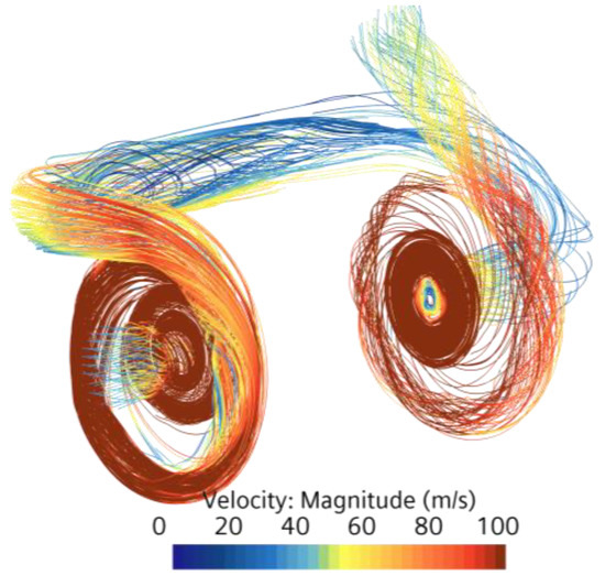
Figure 1.
Gas velocity streamline cloud map.
The thickness of the fluid boundary layer is an important factor affecting the convective heat transfer. Figure 2 shows the velocity cloud diagram of the inner surface of the TSEAC. It can be seen from the figure that the gas velocity on the inner surface of the elbow is significantly smaller than that at the volute, and the thickness of the fluid boundary layer is larger, so the elbow has a greater potential for heat dissipation enhancement. By choosing a reasonable heat dissipation structure, increasing the turbulence near the inner wall of the elbow, and making the flow resistance in the pipe not significantly increase, the heat dissipation can be effectively increased, and the efficiency of the TSEAC can be improved.
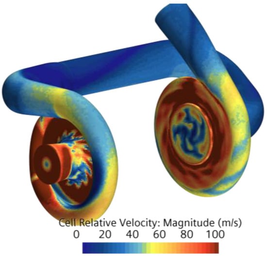
Figure 2.
The inner surface velocity cloud map of the TSEAC.
In order to verify the accuracy of the simulation, an experimental bench for the external characteristics of the TSEAC was built. The experimental bench is mainly composed of gas supply, power supply, control and cooling equipment. Air supply equipment includes: TSEAC (rated 28 kW), air filter, intake pipe (2 pieces), several clamps, reducing pipe, gas detection pipe (including two inlet and outlet pressure sensors, inlet and outlet gas Two temperature sensors, one flow sensor, the selected sensor parameters are shown in Table 1), electromagnetic back pressure valve. Power supply and control equipment include: high-voltage DC power supply (35 kw), low-voltage DC power supply (24 v), wiring plugs; wiring harness: high-voltage cable main + low-voltage cable, communication harness, three-phase line (for connecting TSEAC and controller), CAN box USB cable; cooling equipment includes: cooling water pipes (3 pieces), clamps, reducing diameter, industrial chiller (model: AK1AS); its main components are shown in Figure 3.

Table 1.
Experimental sensor parameters.
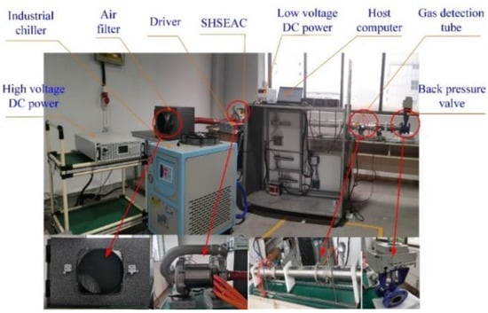
Figure 3.
The experimental bench for the external characteristics of the TSEAC.
In the experiment, the speed of the TSEAC through the host computer was set to 90,000 rpm, and by changing the opening of the back pressure valve, the temperature and pressure results corresponding to different flow rates at this speed were obtained, and the experimental results were compared with the simulation results. Figure 4 It is a comparison chart between the experimental results and the simulation results at 90,000 rpm speed. It can be seen from the figure that the maximum error between the experimental and simulation results is 2.3%, which verifies the accuracy of the simulation.
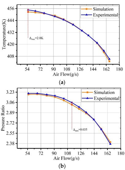
Figure 4.
Comparison of experimental and simulation results. (a) Temperature-flow curve, (b) pressure ratio-flow curve.
3. Analysis of Influence of Heat Dissipation on TSEAC Efficiency
For the compression process of a TSEAC with cooling, under the condition of constant inlet pressure and temperature, TSEAC can reduce the first-stage outlet pressure by cooling the first-stage shell to reduce the internal power consumption of compressed gas. Cooling the first-stage shell and the intermediate elbow can reduce the second-stage inlet temperature and save the second-stage variable compression work under the same pressure ratio [20]. Under the condition that the inlet pressure of the second stage remains unchanged, cooling the shell of the second stage can reduce the outlet pressure of the second stage and save the compression work. The compression work of TSEAC in this study is:
where, W1 and W2 are the compression work of the first and second stages of the TSEAC, respectively.
Where [18]:
where m is the variable process index, ρ is the air density, R is the ideal gas constant, p1 is the gas pressure at the TSEAC inlet, Tin is the TSEAC inlet temperature, qm is the air mass flow, and Cp is the air constant. Specific heat capacity, T1, T2, T3 are the gas temperatures at the first-stage outlet, the second-stage inlet and the second-stage outlet under the adiabatic compression process, respectively, Q1, Q2, Q3 are the heat dissipation of the first-stage volute, the first-stage volute The heat dissipation of the first-stage volute and elbow, and the heat dissipation of the entire TSEAC housing.
In order to verify the energy-saving effect of heat dissipation on the TSEAC, different heat dissipation values are set on the wall surface to simulate and calculate, and the load torque-heat dissipation curve is obtained, as shown in Figure 5. It can be seen from the figure that with the increase of the heat dissipation of the shell, the load torque gradually decreases. When the heat dissipation is 0, it is adiabatic compression. At this time, the load torque is the largest, and the heat dissipation reaches the maximum value Q = 7990 J/s It is isothermal compression, and the load torque is the smallest at this time. The closer the actual compression process is to isothermal compression, the better the energy saving effect.
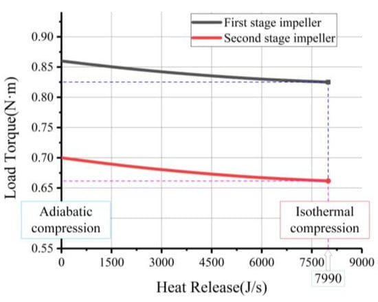
Figure 5.
Load torque-heat dissipation curve of TSEAC.
4. Heat Dissipation Enhancement Method based on Field Synergy Theory
Considering the analogy between convection and conduction, convective heat transfer is essentially the conduction of heat from fluid motion. Considering the steady-state 2D boundary layer flow on a cold plate at zero incidence angle, the energy equation is:
where, cp is the specific heat capacity, k is the thermal conductivity, u and v are the velocity components, x and y are the Cartesian coordinates, and T is the temperature.
The integral of the above formula over the thickness of the thermal boundary layer is:
where, δt is the thermal boundary layer thickness.
It can be seen from Equation (5) that the wall heat flux density is equal to the total intensity of the heat source in the thermal boundary layer. This means that convective heat transfer can be enhanced by increasing the integral amount of the thermal boundary layer convection term (heat source).
Equation (5) can be rewritten in the vector form of the convection term as:
It can be seen from Equation (6) that under a certain flow rate and the temperature difference between the wall and the incoming flow, the wall heat flow increases with the decrease of the angle between the velocity and the temperature gradient/heat flow vector. Equation (6) is also valid for laminar duct flow if the upper limit of the integral is the duct radius.
The dimensionless variables for boundary layer flow are as follows:
where, U is the speed.
Equation (6) can be written in dimensionless form:
where, Nu is the Nusselt number, Re is the Reynolds number, and Pr is the Prandtl number.
As can be seen from Equation (8), there are two ways to enhance heat transfer: (a) increase the Reynolds number or Prandtl number, which is well known; (b) increase the value of the dimensionless integral.
In the dimensionless integration of Equation (8),the vector dot product can be expressed as:
where β is the angle between the velocity vector and the temperature gradient (heat flow vector). It can be known from Equation (9) that there are two vector fields U and , or three scalar fields , and cosβ, in the convection domain. Therefore, the strength of convective heat transfer depends not only on fluid velocity and temperature gradient, but also on their synergy.
Therefore, the principle of field synergy to enhance convective heat transfer is as follows: under other conditions being equal, the better the synergy between velocity gradient and temperature gradient, the higher the convective heat transfer rate. This points us to the method of enhancing convective heat transfer (a) the angle between the velocity and the temperature gradient/heat flow should be as small as possible, that is, the velocity and the temperature gradient should be as parallel as possible; (b) the local values of the three scalar fields should be large at the same time, the greater the value of cosβ, the greater the value of velocity gradient and temperature gradient; (c) The velocity and temperature distribution on each section should be as uniform as possible. The better the synergy of these three scalar fields, the higher the value of the Nusselt number [21].
In the case of small local velocity and temperature gradients, only the local good synergy contributes little to the enhancement of convective heat transfer. As mentioned above, the most favorable case is when small angles are accompanied by large velocity and temperature gradients. The effect of this ideal situation can be reflected in the final result, the integration of the convection term over the entire domain, so the over-increasing element introduces a dimensionless number Fc and is designated as the field synergy number. As shown in the following formula [21]:
where Fc is the field synergy number, which represents the degree of synergy between the velocity gradient field and the temperature gradient field in the entire region. Its value can be anywhere between 0 and 1, depending on the type of heat transfer surface. The field synergy principle points us to the direction of improving convective heat transfer under given conditions (for example, flow rate and temperature difference), and provides a basis for evaluating the effect of convective heat transfer.
5. Micro-Fin Tube Strengthens Heat Dissipation Structure Design
The synergistic analysis of the turbulent heat transfer field indicates that the longitudinal vortices or disturbances near the wall can effectively enhance the turbulent heat transfer in the flow near the bottom of the laminar flow, while the increase of flow resistance is as small as possible. According to the numerical calculation in Chapter 1, the Reynolds number in the elbow of the TSEAC is 105155, and the gas is in a turbulent state. In this flow state, the micro-fin tube has been proved by many studies to be an enhanced heat transfer structure that meets the requirements of both friction coefficient and heat transfer capacity [22,23,24]. In this paper, a micro-fin structure is designed on the inner wall of the TSEAC, and its heat transfer performance is analyzed based on the field synergy theory. The micro-fin tube structure is shown in Figure 6.

Figure 6.
Structure diagram of micro-fin tube to strengthen heat dissipation.
The rib height is the parameter that has the greatest influence on the heat dissipation effect, and its value is related to the thickness of the laminar bottom layer. The ratio of the height of the micro-fin to the thickness of the laminar bottom layer (ε/δ) directly affects the convective heat transfer intensity and flow resistance, and the thickness of the laminar bottom layer for:
In order to determine the height of the micro-fin suitable for the working conditions of the TSEAC, different values in the range of ε/δ = 0−2 are used for simulation analysis, and the Nusselt number and the pressure drop in the pipe under different micro-fin heights are obtained, as shown in the Figure 7 is shown.
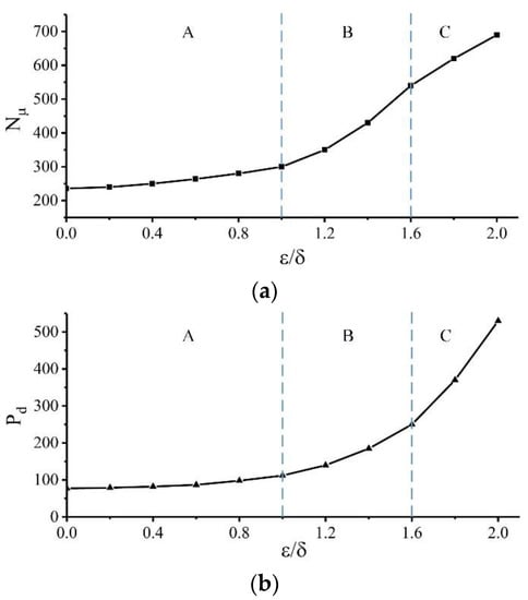
Figure 7.
(a) Nusselt number at different micro-fin heights, (b) Intra-pipe pressure drop at different micro-fin heights.
In the A region where ε/δ < 1, the micro-fin height is lower and the micro-fin is completely covered by the laminar bottom layer. At this time, the function of micro-fins is mainly to increase the heat exchange area in the tube, and the disturbance to the flow boundary layer is small, the increase in resistance is small, and the heat transfer efficiency of the micro-fin tube is also low. As the height of the micro-fins increases, the height of the micro-fins is the same as the thickness of the laminar bottom layer when ε/δ = 1, reaching the transition point where the heat transfer and resistance in the tube change, and the heat transfer efficiency begins to increase rapidly. As ε/δ continues to increase, in the B region where ε/δ > 1, the height of the micro-fin is gradually larger than the thickness of the laminar bottom layer, which will cause segmentation and damage to the laminar bottom layer. Longitudinal vortices are generated during the fluid flow at high speed. According to the field synergy theory [21], the longitudinal vortex with radial flow can improve the synergy between the velocity field and the temperature field in the tube, and play a role in strengthening heat transfer. Therefore, the Nu in the tube of the micro-fin tube is greatly increased, thereby increasing the heat dissipation of the elbow of the TSEAC and improving the efficiency of the TSEAC. When ε/δ increases further and reaches the C region where ε/δ > 1.6, the micro-fin penetrates deep into the turbulent region, and the disturbance effect of the micro-fin on the fluid gradually weakens. The main reason why the heat exchange effect continues to increase at this time is that the heat exchange area increases, thereby improving the heat transfer between the wall surface and the mainstream fluid. However, as the height of the micro-fin increases, the flow resistance of the elbow increases rapidly, resulting in a large pressure drop in the pipe, which adversely affects the overall efficiency of the TSEAC.
According to the above analysis, the increase of the micro-rib height will enhance the heat dissipation capacity of the elbow and improve the efficiency of the TSEAC, but the increase of the micro-rib height will also increase the pressure drop in the tube and reduce the efficiency of the TSEAC. Therefore, in order to comprehensively consider the effect of enhanced heat dissipation and the increase of flow resistance on the overall efficiency of TSEAC, this paper quotes the efficiency index η to evaluate different micro-fin heights, and its expression is:
where, Pd is the pressure drop in the tube.
According to the results in Figure 7, the efficiency index η is the largest when ε/δ = 1.6, indicating that the increase in resistance is small and the heat exchange efficiency is large at this time, which is most conducive to improving the overall efficiency of the TSEAC. In this paper, the other parameters of the micro-fin tube are quoted from the commonly used values in the industry, so as to determine the structural parameters of the micro-fin tube, as shown in Table 2.
Table 2.
Structural parameters of micro-fin tube.
6. Strengthening the Heat Dissipation Structure to Verify the Efficiency Improvement
According to the analysis in the previous chapter, the micro-fin tube can improve the synergy between the velocity field and the temperature field on the inner wall of the TSEAC elbow, thereby enhancing the convection heat transfer and reducing the compression work. In order to verify the enhanced heat transfer effect of the micro-fin tube mentioned in the previous chapter, the simulation analysis of the TSEAC before and after optimization is carried out, and the temperature cloud diagram in the flow field is obtained, as shown in Figure 8. As can be seen from the figure, due to the axial suction generated by the rotation of the impeller, a certain negative pressure is generated at the inlet of the first stage, so that the gas temperature at the inlet is slightly lower than the ambient temperature by 300 K. At the outlet of the second stage, the outlet temperature of the TSEAC with the micro-fin tube structure is significantly lower than that of the smooth wall. For the first and second compression stages, because the enhanced heat exchange occurs in the elbow after the first stage outlet, the optimized gas temperature at the first stage outlet does not change much, while the second stage inlet and outlet The gas temperature is significantly lower than before optimization.
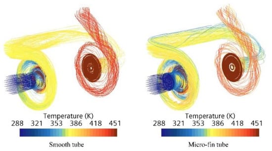
Figure 8.
Comparison of temperature fields of TSEAC.
Under the condition that the impeller speed remains unchanged, the energy saving effect of the optimized TSEAC lies in the reduction of the load torque. The load torque of the impeller is generated by the pressure difference between the pressure side and the suction side of the blade. Figure 9 shows the blade surface pressure nephograms of the first and second stage impellers before and after optimization. It can be seen from the figure that after the enhanced heat exchange structure is added, the pressure on the pressure surface of the first and second stage impellers of the TSEAC is reduced, while the pressure on the suction surface does not change much, so the load power of the impeller is reduced, and the air pressure is reduced. Machine efficiency is improved. The energy-saving optimization effect of the second-stage impeller is obviously stronger than that of the first-stage impeller. This is because the inlet temperature of the second-stage is reduced after the heat dissipation is enhanced at the elbow, so that the inlet gas pressure of the second-stage is reduced, thereby reducing the second-stage gas pressure. Load torque of the impeller.
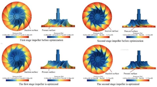
Figure 9.
Blade surface pressure cloud map.
Aiming at the common working conditions of the impeller speed of 90,000 rpm and the flow rate of 68 g/s in this study, this paper obtained the load torque of the TSEAC before and after the enhanced heat dissipation structure through simulation. The load torques before and after optimization are 1.540 N·m and 1.509 N·m, respectively, and the shaft power is 14.51 kW and 14.22 kW respectively. Compared with before optimization, the TSEAC efficiency after optimization is increased by 1.9%.
7. Conclusion
In this paper, the TSEAC for fuel cells is taken as the research object, and the internal gas flow characteristics of the TSEAC are analyzed by simulation, and the experimental verification is carried out. The feasibility of increasing the heat dissipation to improve the efficiency of the TSEAC is studied, and the heat dissipation structure of the inner wall of the TSEAC is optimized by using the field synergy theory. According to the common working conditions of fuel cell TSEAC, this paper designs a micro-fin tube structure that can effectively improve the efficiency of the TSEAC, and the design effect is verified. The main conclusions are as follows:
(1) Enhancing the heat dissipation of the shell can effectively improve the efficiency of the TSEAC for fuel cells. The gas velocity at the elbow between the first and second compression stages of the fuel cell TSEAC is small and the flow is uniform. Adding a heat dissipation structure to the inner wall of the elbow can improve the synergy between the velocity field and the temperature field at the wall, thereby effectively improving the efficiency of the TSEAC.
(2) The micro-fin tube is a heat dissipation enhancement structure suitable for the working condition of the fuel cell TSEAC. Considering the influence of heat dissipation enhancement capability and flow resistance, the ratio of the height of the micro-fin to the thickness of the laminar bottom layer is ε/δ = 1.6 Energy saving is the best. Compared with the smooth inner wall of the elbow, the optimized TSEAC efficiency is improved by 1.9%. It is worth noting that the fabrication of micro-fin structures in irregular bends is complicated. In addition, In order to obtain better energy-saving effect, it is necessary to choose a shell material with higher thermal conductivity and an effective heat dissipation structure on the outer wall.
Author Contributions
Conceptualization, J.Z. and Q.S.; methodology, C.F.; software, X.W.; validation, J.Z.; formal analysis, J.Z.; investigation, F.Y.; resources, C.J.; data curation, J.Z.; writing—original draft preparation, J.Z. and F.Y.; writing—review and editing, J.L.; visualization, Z.F.; supervision, S.J.; project administration, J.L.; funding acquisition, D.H. All authors have read and agreed to the published version of the manuscript.
Funding
This research was supported by the National Natural Science Foundation of China [U1842620], the national key research and development plan [2018YFB0106501], the national key research and development plan [2018YFB1600303], the natural science foundation of Shandong Province [ZR2019MEE029] and Graduate Interdisciplinary Innovation Project of Yangtze Delta Region Academy of Beijing Institute of Technology (Jiaxing) [NO.GIRP2021-017].
Institutional Review Board Statement
Not applicable.
Informed Consent Statement
Not applicable.
Data Availability Statement
The data presented in this study are available on request from the corresponding author.
Conflicts of Interest
The authors declare no conflict of interest.
References
- Tao, Y.; Qiu, J.; Lai, S.; Zhang, X.; Wang, G. Collaborative Planning for Electricity Distribution Network and Transportation System Considering Hydrogen Fuel Cell Vehicles. IEEE Trans. Transp. Electrif. 2020, 6, 1211–1225. [Google Scholar] [CrossRef]
- Ma, R.; Li, Z.; Breaz, E.; Liu, C.; Bai, H.; Briois, P.; Gao, F. Data-Fusion Prognostics of Proton Exchange Membrane Fuel Cell Degradation. IEEE Trans. Ind. Appl. 2019, 55, 4321–4331. [Google Scholar] [CrossRef]
- Hu, D.; Wang, Y.; Li, J.; Yang, Q.; Wang, J. Investigation of optimal operating temperature for the PEMFC and its tracking control for energy saving in vehicle applications. Energy Convers. Manag. 2021, 249, 114842. [Google Scholar] [CrossRef]
- Zhao, D.; Xu, L.; Huangfu, Y.; Dou, M.; Liu, J. Semi-physical modeling and control of a centrifugal compressor for the air feeding of a PEM fuel cell. Energy Convers. Manag. 2017, 154, 380–386. [Google Scholar] [CrossRef]
- Zhou, J.; He, H.; Li, J.; Yi, F.; Hu, D.; Yi, J. Stability Expansion Control Method of Ultra-High Speed Electric Air Compressor for Hydrogen-Oxygen Fuel Cell Vehicle. CN Patent 112582646A, 19 October 2021. [Google Scholar]
- Yi, F.; Lu, D.; Wang, X.; Pan, C.; Tao, Y.; Zhou, J.; Zhao, C. Energy Management Strategy for Hybrid Energy Storage Electric Vehicles Based on Pontryagin’s Minimum Principle Considering Battery Degradation. Sustainability 2022, 14, 1214. [Google Scholar] [CrossRef]
- Zhang, H.; Li, X.; Liu, X.; Yan, J. Enhancing fuel cell durability for fuel cell plug-in hybrid electric vehicles through strategic power management. Appl. Energy 2019, 241, 483–490. [Google Scholar] [CrossRef]
- Wan, Y.; Guan, J.; Xu, S. Improved empirical parameters design method for centrifugal compressor in PEM fuel cell vehicle application. Int. J. Hydrogen Energy 2016, 42, 5590–5605. [Google Scholar] [CrossRef]
- Tirnovan, R.; Giurgea, S.; Miraoui, A.; Cirrincione, M. Modelling the characteristics of turbocompressors for fuel cell systems using hybrid method based on moving least squares. Appl. Energy 2009, 86, 1283–1289. [Google Scholar] [CrossRef]
- Kim, J.-H.; Choi, J.-H.; Husain, A.; Kim, K.-Y. Multi-objective optimization of a centrifugal compressor impeller through evolutionary algorithms. Proc. Inst. Mech. Eng. Part A J. Power Energy 2010, 224, 711–721. [Google Scholar] [CrossRef]
- Yagi, M.; Kishibe, T.; Shibata, T.; Nishida, H.; Kobayashi, H. Performance Improvement of Centrifugal Compressor Impellers by Optimizing Blade-Loading Distribution. In Proceedings of the 53rd ASME Turbo Expo, Berlin, Germany, 9–13 June 2008; pp. 1639–1648. [Google Scholar]
- Li, D.; Yang, C.; Zhou, M.; Zhu, Z.; Wang, H. Numerical and experimental research on different inlet configurations of high speed centrifugal compressor. Sci. China Technol. Sci. 2011, 55, 174–181. [Google Scholar] [CrossRef]
- Kim, S.; Park, J.; Ahn, K.; Baek, J. Improvement of the Performance of a Centrifugal Compressor by Modifying the Volute Inlet. J. Fluids Eng. 2010, 132, 091101. [Google Scholar] [CrossRef]
- Milburn, S.; Cronin, J.; Cohen, B. A Variable Displacement Compressor/Expander for Vehicular Fuel Cell Air Management; Sae Technical Papers; SAE: Boulder, CO, USA, 1996. [Google Scholar] [CrossRef]
- Cho, L.; Lee, S.; Cho, J. Use of CFD Analyses to Predict Disk Friction Loss of Centrifugal Compressor Impellers. Trans. Jpn. Soc. Aeronaut. Space Sci. 2012, 55, 150–156. [Google Scholar] [CrossRef][Green Version]
- Dragan, V. Centrifugal Compressor Efficiency Calculation with Heat Transfer. IIUM Eng. J. 2017, 18, 225–237. [Google Scholar] [CrossRef]
- Gu, L.; Zemp, A.; Abhari, R.S. Numerical study of the heat transfer effect on a centrifugal compressor performance. Proc. Inst. Mech. Eng. Part C J. Mech. Eng. Sci. 2014, 229, 2207–2220. [Google Scholar] [CrossRef]
- Hu, D.; Liu, J.; Yi, F.; Yang, Q.; Zhou, J. Enhancing heat dissipation to improve efficiency of two-stage electric air compressor for fuel cell vehicle. Energy Convers. Manag. 2021, 251, 115007. [Google Scholar] [CrossRef]
- Hu, D.; Yang, L.; Yi, F.; Hu, L.; Yang, Q.; Zhou, J. Optimization of speed response of super-high-speed electric air compressor for hydrogen fuel cell vehicle considering the transient current. Int. J. Hydrogen Energy 2021, 46, 27183–27192. [Google Scholar] [CrossRef]
- Pan, P.; Yuan, C.; Sun, Y.; Yan, X.; Lu, M.; Bucknall, R. Thermo-economic analysis and multi-objective optimization of S-CO2 Brayton cycle waste heat recovery system for an ocean-going 9000 TEU container ship. Energy Convers. Manag. 2020, 221, 113077. [Google Scholar] [CrossRef]
- Guo, Z.; Tao, W.; Shah, R.K. The field synergy (coordination) principle and its applications in enhancing single phase con-vective heat transfer. Int. J. Heat Mass Transf. 2005, 48, 1797–1807. [Google Scholar] [CrossRef]
- Carnavos, T.C. Heat Transfer Performance of Internally Finned Tubes in Turbulent Flow. Heat Transf. Eng. 1980, 1, 32–37. [Google Scholar] [CrossRef]
- Celen, A.; Dalkilic, A.S.; Wongwises, S. Experimental analysis of the single phase pressure drop characteristics of smooth and microfin tubes. Int. Commun. Heat Mass Transf. 2013, 46, 58–66. [Google Scholar] [CrossRef]
- Mann, G.W.; Eckels, S. Multi-objective heat transfer optimization of 2D helical micro-fins using NSGA-II. Int. J. Heat Mass Transf. 2018, 132, 1250–1261. [Google Scholar] [CrossRef]


Publisher’s Note: MDPI stays neutral with regard to jurisdictional claims in published maps and institutional affiliations. |
© 2022 by the authors. Licensee MDPI, Basel, Switzerland. This article is an open access article distributed under the terms and conditions of the Creative Commons Attribution (CC BY) license (https://creativecommons.org/licenses/by/4.0/).