Abstract
Coal has been an energy source exploited for several decades, with its extraction being linked to creating wastes. Surface mines’ overburden and interburden materials are typically dumped in spoil heaps, many times without considering their future use. Nowadays, sustainability and circular economy principles demand the efficient valorization of these areas. In that vein, this work investigates alternatives from a geotechnical perspective with shallow foundations for the reclamation of a massive spoil heap. Initially, the installation with a raft foundation of a wind turbine was investigated through a serviceability limit envelope employing 3D finite element analysis. However, the spoil material is too soft to withstand such a massive superstructure, and more advanced foundation techniques are needed. Moreover, the installation of supportive constructions was examined, i.e., buildings with shallow isolated footings using a similar approach and 3D finite element analysis. The soil-footing response is much dependent on the constitutive model, and the potential of small buildings requires further attention. Overall, for the appropriate valorization of the spoil heap, it appears that ground improvement or deep foundations are necessary. This conclusion stands for many similar spoil heaps globally due to the material’s nature.
1. Introduction
Coal has significantly contributed to the global energy needs for several decades, accounting for 25% of the global energy production in 2000, 30% in 2010, and 27% in 2020 [1]. The transition to cleaner forms of energy has led to mine closures in several regions across Europe and globally. With this shift in the energy mix and the groundbreaking changes in the economy’s structure, many coal regions’ economic and social impact should not be ignored. Coal mining areas and waste dumps will be abandoned during decarbonization and will burden local and national communities unless suitably reclaimed.
Coal excavations are connected with the creation of waste. Extraction of coal and lignite (brown coal) near the surface (opencast, open-pit, or other types of surface mining) involves excavating the overburden material. This material, called spoil waste, is usually transported and dumped in nearby areas forming massive spoil heaps, also called waste dumps, spoil piles, or colliery spoil dumps. Following coal and lignite excavation, numerous spoil dumps have been created worldwide. Recent thinking has been considering such materials as a resource rather than waste. These vast areas should now be adapted to the post-lignite era within this concept. However, these waste materials pose significant challenges, mainly due to the highly heterogeneous spoil nature [2]. Finding the appropriate ways to manage them efficiently is a global priority challenging engineers, researchers, and communities, e.g., see [3]. In this context, advanced risk management methodology can support the planning of the revitalization process of post-mining heaps (Bialas 2022). Climatic changes should also be considered in this new era, as temperature, rainfall, and wind speed evolution might crucially affect the areas’ safety and reclamation practices.
Stakeholders, engineers, and communities are searching for ways to reinvent spoil dumps’ areas, being on the verge of the post-coal and post-lignite era. Various reclamation directions have been proposed and implemented. They commonly include simple landscape restoration with natural or artificial vegetation and forestry development [4,5,6] and recreational areas with open-pit lakes and green zones. For instance, Kasztelewicz [7] presented various cases of post-mining reclamation in Poland that serve as such areas. However, more efficient solutions have also been proposed due to their vast areas and global energy transformation and needs. They commonly include reclamation of coal areas for energy production and storage (e.g., wind farms and underground energy storage). Several are already in place or under consideration in Europe and the USA [8].
These plans pose challenges related to the proposed solutions’ safety and cost-efficiency, mainly related to the geotechnical aspects of the reclamation plans. Skinner et al. [9] discussed the essential geomechanical features (bearing capacity, settlements) regarding the potential use of colliery spoil heaps as foundation ground. However, significant challenges accompany this direction because spoil significantly differs from its pre-excavated state, and its physical and engineering properties can be highly disturbed and variable. Several studies examined the stability of spoil heaps and tailings dams, e.g., see [2,10,11,12,13], but very few include detailed characterization of the spoil material, e.g., see [12,14,15]. Masoudian, Zevgolis, Deliveris, Marshall, Heron, and Koukouzas [2] presented a state-of-the-art review on spoil characterization and slope stability. Using data from several European mines, they concluded that spoils present significant variability both spatially and temporally.
In this work, the significant issue of valorization is evaluated by investigating alternatives for the reclamation of coal and lignite spoil heaps principally from a geomechanical perspective. These are typical reclamation options for many types of spoil heaps globally, and this work presents an initial examination of their implementation. A massive spoil heap, whose geotechnical properties have been systematically analyzed in the past [16], was employed as a reference for the analysis. Overall, this work aims to answer whether heaps of lignite mines, such as the spoil heap under investigation, can be used for wind turbines as renewable energy projects, buildings needed for several valorization plans, or other infrastructure, by employing shallow foundation systems. Criteria based on international design standards were set for each of the different scenarios. Mainly 3D finite element analysis was employed, accompanied by literature, design standards, and regulations to determine the spoil’s suitability in each case. The conclusions are largely general and stand for many spoil heaps globally due to the material’s nature.
2. Materials and Methods
2.1. The Spoil Material
Greece has been a leading lignite (brown coal) producer in Europe, mining 37.7 million tons of lignite in 2017 [17] and 13.1 million tons of lignite in 2020 (Euracoal 2021). Several vast and deep lignite mines have been developed in the Western Macedonia Lignite Centre in north-western Greece. During the last 15 years, the stripping ratio (volume of waste material for 1 ton of lignite) has been about 4–5 m3/ton [18]. A result of this surface mining activity and the geometry of the lignite deposits has been the creation of massive spoil heaps.
One such spoil heap has been constructed on a depleted mining area between two surface lignite mines (Kardia and South Field) with sterile materials. Typical ground profiles of the adjacent mines’ excavations present a thick overburden zone of sterile materials (Quaternary deposits of several tens of meters) overlaying the lignite layers (Neogene deposits). The lignite deposits alternate with thin layers of sterile material, while combustible material can also be found in the sterile layers. The sterile material consists of marls, stiff to hard clays, sporadically weak conglomerates, and water-bearing sands. The initial phases of the spoil heap began in 1999 when its creation started. The heap’s maximum height, about 170 m, was reached in 2009, and since then, only widening has occurred. The spoil heap is about 5 km long, 0.4–2.1 km wide at its top, and 1.80–3.65 km wide at its base.
The soil body is highly heterogeneous due to the extraction and dumping processes related to the heap’s construction. Nevertheless, the soil mass was considered one unified spoil material with significant uncertainty for practical purposes in the analysis. This assumption was analyzed in-depth by Zevgolis et al. [16] and was based on extended experimental results. Very briefly, in the spoil heap, a great variety of soil types appear in a spatially random arrangement. Extensive efforts to distinguish a stratigraphy in the spoil heap have failed. Furthermore, not even one particular structure can be easily identified, as different materials are intertwined, creating formations that cannot lead to organized patterns. Additional considerations and analysis concluded that an orderly characterization could not be identified. Provided the spoil material’s disordered structure, it was reasonable to employ a statistical treatment of the heap as a single material with significant inherent variability, expressed in common statistical moments. Advanced concepts such as spatial variability of geotechnical properties could offer a more sophisticated numerical modeling, but such an analysis exceeds the aims of the present work.
Table 1 presents the geotechnical characterization of this spoil material, including quantifying its basic statistics [16]. The number of samples used in experiments to determine the parameters of the materials is mentioned as the population. The strength parameters (effective friction angle and cohesion) are from drained triaxial tests, while the stiffness results from 1-D compression (oedometer) tests. As the number of experiments was different, the resulting population was different. The representative material of the spoil heap is high plasticity silt (MH in USCS). The oedometric modulus (Es), the compression (cc), and recompression (cr) indices of the spoil material were determined through 1-D consolidation tests and the soil strength through undrained triaxial tests. Table 1 summarizes the results and indicates a compressible and soft material.

Table 1.
Strength and stiffness of the spoil material modified after [16].
2.2. Numerical Analysis and Constitutive Models
Computational and numerical analysis has undergone a remarkable development during the last decades. This progress led to the development of advanced methods such as the finite element method (FEM), making it possible to analyze, simulate and predict the behavior of granular materials under several conditions and particularly of complex soil structures and soil-structure interaction problems. In this work, the 3D FEM is used as implemented in Plaxis 3D v.2018 [19] to analyze the soil response when a structure is considered to be built for spoil valorization.
The FEM depends on appropriately representing the relations between stresses and strains for the various materials. The constitutive model is responsible for these stress-strain relations in numerical computations, consisting of mathematical expressions that model the behavior of the soil in a single element. Significant developments in constitutive models have occurred over the past four decades. The initial models were relatively simple, but a progression in complexity and capabilities of the models have led to many improved abilities in capturing the behavior of soils and structures under complex loading conditions. Characterization of soil behavior can become crucial because the stress-strain relations are non-linear.
The present study employs three previously calibrated models on undrained triaxial laboratory results of the spoil material, specifically the Mohr–Coulomb, the Hardening Soil, and the Soft Soil model [20]. The experimental data were from three undrained triaxial tests with pore pressure measurements, and the calibrations were further validated by 1-D compression (oedometric) tests. The three triaxial tests were representative of the experimental program in terms of material classification, strength, and stiffness. Table 2 summarizes the calibrated parameters for the three models. The linear elastic perfectly plastic Mohr–Coulomb model is a simple and well-known model widely used in geotechnical engineering, which can be considered a simplified approximation of soil behavior. It proposes a bilinear soil response; the linear elastic part of this model is based on isotropic elasticity (based on Hooke’s law), and the perfectly plastic part is based on the Mohr–Coulomb failure criterion, formulated in a non-associated plasticity framework.
Table 2.
Calibrated parameters for the spoil material.
The Hardening Soil model is an advanced model for simulating the soil behavior, mainly incorporating an elasto-plastic framework based on classical plasticity and isotropic hardening and providing a non-linear response. Apart from the non-linearity of the response, other significant elements include the failure according to the Mohr–Coulomb failure surface, stress-dependent stiffness, plastic strains (isotropic hardening) by primary deviatoric loading and compression, and an elastic unloading/reloading response different from the primary loading. Finally, the Soft Soil model has similar features to the Hardening Soil and significant differences. It includes failure behavior following the Mohr–Coulomb criterion, stress-dependent stiffness, and a distinction between primary loading and unloading-reloading. However, it considers a logarithmic relation between changes in volumetric strain and changes in mean effective stress and is formulated based on the parameters λ* and κ*, which are related to the compression–recompression indices. Furthermore, it implements an elliptical yield surface. Without further validation, at least the Hardening Soil and the Soft Soil models would be appropriate to model the soil behavior in this work accurately, but Mohr–Coulomb could also be used at a preliminary stage.
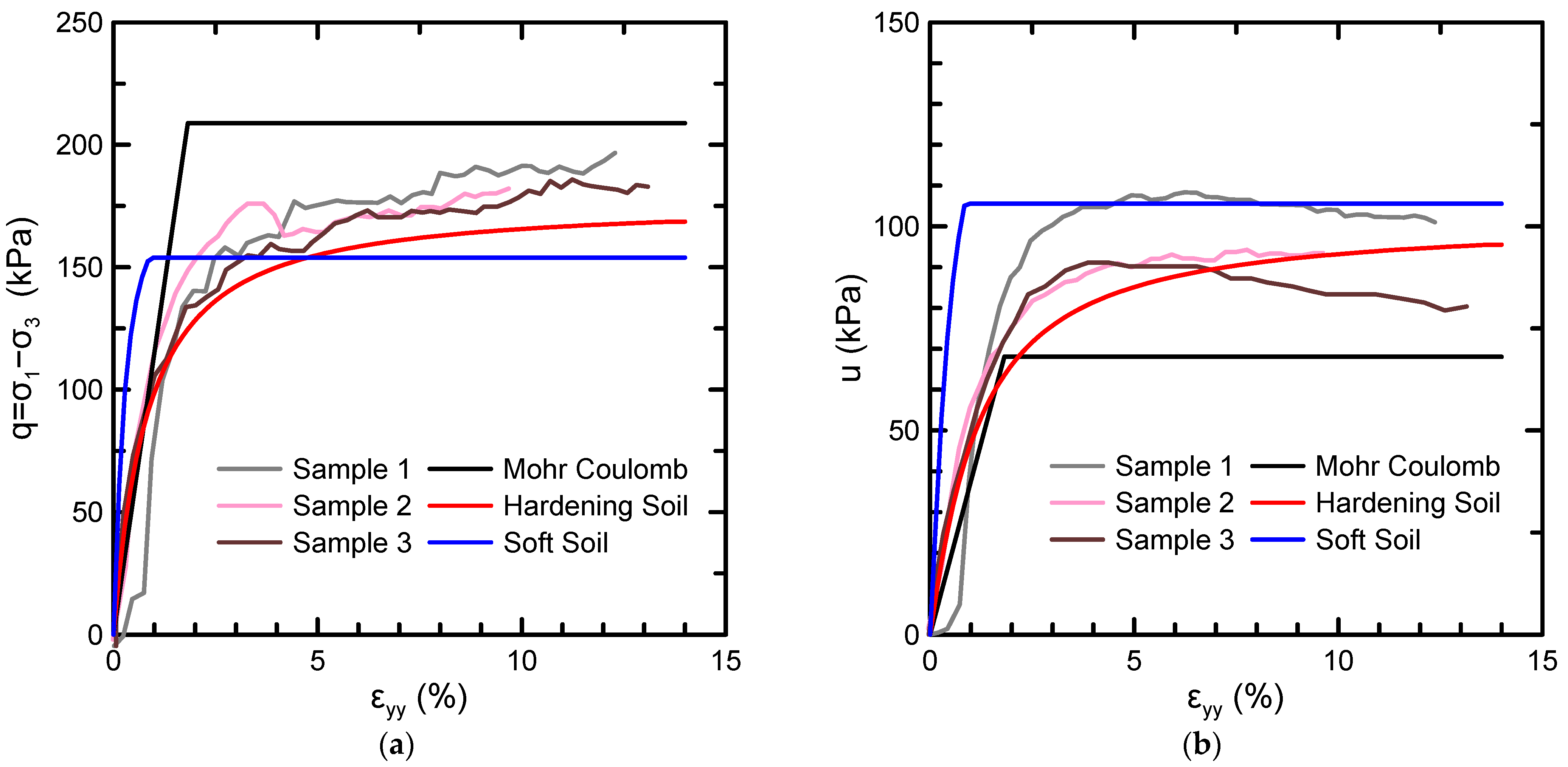
The Mohr–Coulomb model adequately fitted the apparent monotonic behavior but could not accurately quantify the pore pressure build-up. The Hardening Soil model described better the pore pressure increase and the non-linear response during undrained triaxial shear. However, the numerical model built up the pore pressures more rapidly than the experimental results. Finally, the Soft Soil model more accurately represented the pore pressure build-up but proposed a more rapid deviatoric stress increase than the experimental one. Overall, the three constitutive models adequately described the spoil material’s monotonic behavior, each having advantages and drawbacks. Figure 1 presents the representative case of the undrained triaxial tests with cell pressure of 200 kPa and the three calibrated constitutive models.

Figure 1.
(a) Deviatoric stress and (b) pore pressure build-up versus axial strain for three undrained triaxial tests (cell pressure 200 kPa), and the three constitutive models.
3. Numerical Modeling
3.1. Wind Turbine Installation with Raft Foundation
The efficient and sustainable reclamation of the vast spoil areas will contribute significantly toward a more sustainable post-lignite era. Wind turbines are massive superstructures using wind to produce energy. The technology of wind turbines continuously develops as they are becoming better at creating wind power at variable wind speeds. As a result, they have larger rotors, higher towers, and lighter blades, and the resulting energy grid is more stable. Additionally, the cost reductions will continue as the turbines become larger, with taller towers and lighter construction, and the scale of wind installations increases. They have three parts: the tower (that can be constructed with steel, concrete, or both), the mechanical parts (rotor, blades, nacelle), and the foundation. The foundation is one of the most cumbersome parts as it carries heavy loads and has strict constraints on settlements and rotations. Thus, installing a wind turbine on the spoil heap areas is largely determined by the foundation capabilities herein investigated.
The loads transported to the foundation come from three sources: the tower and the foundation weights (dead loads), the wind power, and a moment transferred on the foundation due to the mechanical parts’ eccentricity (rotor nacelle). The magnitude of these loads varies depending on the superstructure’s dimensions and materials and the climatic conditions (mainly wind). The wind pushing on the tower is the most critical load, creating a considerable horizontal force and a vast overturning moment.
Wind turbines are categorized in many ways, yet, the primary categorization is through their output capacity. Medium-sized wind turbines (order of 2 MW) are the most common. For that reason, their loads are used in this work, considering that larger wind turbines might be even more beneficial. Some representative case studies are briefly discussed to obtain these loads’ ranges. Grunberg and Goehlmann [21] examined a typical medium-sized wind turbine made of concrete and steel, and Shrestha et al. [22] and Shrestha and Ravichandran [23] presented an additional analysis of various weather conditions. Mohamed and Austrell [24] and Baniotopoulos et al. [25] worked on a steel-only wind turbine performing structural analysis and focusing on the superstructure’s structural integrity. Table 3 summarizes these loads. Significant differences in dead loads were due to the tower’s material, while differences in the horizontal forces and bending moments were due to the towers’ different heights.
Table 3.
Typical medium-sized wind turbines’ loads.
Shallow foundations have been implemented for onshore wind turbines, mainly shallow cylindrical rafts. Other types are mainly deep foundations such as piles or a combination of a raft with piles. In the present study, the emphasis is on preliminary evaluation and shallow foundations, and only the cylindrical raft is examined. The raft’s size varies significantly depending on the superstructure dimensions, the construction materials, and the soil. In that vein, several values for the diameter were tested to obtain the order of magnitude for the foundation’s size. Small diameter rafts are discarded due to their inadequacy to withstand the wind turbine loads, and only large diameters can be considered. One cylindrical raft of 20 m in diameter and 2.5 m in thickness was herein chosen and investigated.
The following methodology is employed to assess the possibility of wind turbine installation. Initially, the constraints of the foundations are determined. Then these constraints are translated into moments and forces, and a limit envelope with the allowable loads is created. Finally, wind turbines’ typical loads are compared with the envelopes created.
The main restrictions of the foundation include specific criteria for the serviceability limit state so that the wind turbine can be functional. The bearing capacity of wind turbines is rarely the critical mechanism since the vast area covered by the foundation leads to small stresses. Therefore, the criteria used were the maximum allowable settlement and the foundation’s rotation.
The maximum settlement is usually determined in a project-specific manner by the engineer and the turbine manufacturer. The typical settlements for raft foundations were considered, ranging from 7.5 cm to 12.5 cm for raft foundations resting on clayey soils [26]; the mean of 10 cm was selected to serve as the target value. Moreover, the manufacturer usually provides a requirement for the ultimate rotation, which must not be exceeded. In a more general framework, the moment M (applied to the foundation) leads to a rotation θ related to the soil’s rotational stiffness ratio (expressed in MN-m/rad): θ = M/Kθ. The rotational stiffness Kθ equals [27]:
where G is the shear modulus of the soil; ν is the Poisson’s ratio of the soil; R is the foundation’s radius; Df is the foundation’s embedment depth; Hb is the depth to the bedrock below the soil layers. The stiffness of the soil is quantified through the shear modulus G, directly related to Young’s modulus E. Since its value for the present spoil is much lower than in common soils, the rotational stiffness is also small. Typical values in the literature are around 50 GN-m/rad, e.g., see [28], while for the present case, Kθ = 22 GN-m/rad. Standard medium-sized wind turbine moments range from 50 up to 150 MN-m, corresponding to rotations from 0.13° up to 0.40° (Kθ = 22 GN-m/rad). Besides, Eurocode-7 [29,30] proposes a limit value for the angular distortion (w) 1/500, translating to a differential displacement Δu of 0.04 m (as w = Δu/D = 1/500, D equal to 20 m being the raft’s diameter). This differential settlement corresponds to a rotation equal to 0.1° (θ = Δu/D). This rotation angle equal to 0.1° was selected as the limit condition considering the minimum of this and the previous criteria.
A 3D finite element analysis was used to translate the above constraints in settlement and rotation into bearing moment and vertical load and create a limit envelope (Figure 2). The raft was modeled as a rigid body; the wind turbine structure usually does not significantly affect the foundation’s stiffness for onshore wind turbines with a raft foundation. This happens because the raft foundation is very stiff, e.g., built by reinforced concrete of a significant thickness and size, and can be considered rigid. The vertical load and the bearing moment were applied at the center of the foundation; the distribution of the superstructure loads on the foundation affects the results. However, this effect is not significant for the soil settlements and can be neglected if only the soil and not the superstructure is under investigation. The simplified simulation of this work is then good enough to evaluate the soil response [24].
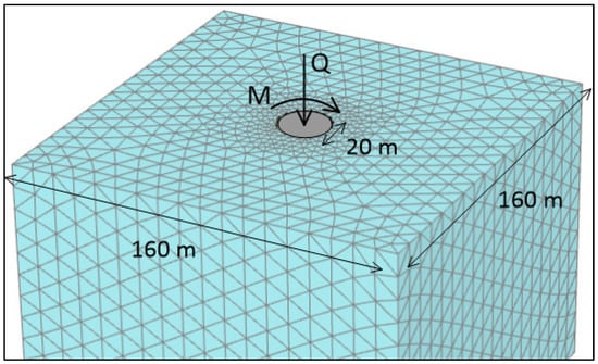
Figure 2.
Finite element discretization and a schematic view of the embedded shallow cylindrical raft foundation.
The three constitutive models presented in Section 2 were used for the spoil material. The finite element mesh was appropriately defined to avoid boundary effects. Triangular 10-noded elements were used, and the mesh was refined in the area near the foundation. Initially, the foundation’s self-weight was applied, and then a vertical load to find the maximum load corresponding to the settlement limit.
Figure 3 illustrates the load-settlement curve for the three constitutive models. The bearing capacity according to Eurocode-7 equations [31] equals 764 MN. This is the theoretical value and, as expected, is extremely large due to the nature of the raft foundation and the bearing capacity equation. The response even up to 2 m of settlement appears to be approximately linear due to the raft foundation’s size, and the bearing capacity has not been reached. Moreover, Figure 4 focuses on the 10 cm serviceability limit; this constraint is satisfied for vertical loads less than 17 MN for the Mohr–Coulomb, 10 MN for the Hardening Soil, and 7 MN for the Soft Soil model. Thus, heavy structures (e.g., made of concrete, see Table 3) are excluded since their self-weight alone is larger than the maximum allowed vertical load.
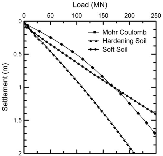
Figure 3.
Load-settlement curves for the shallow cylindrical raft foundation on the spoil heap.
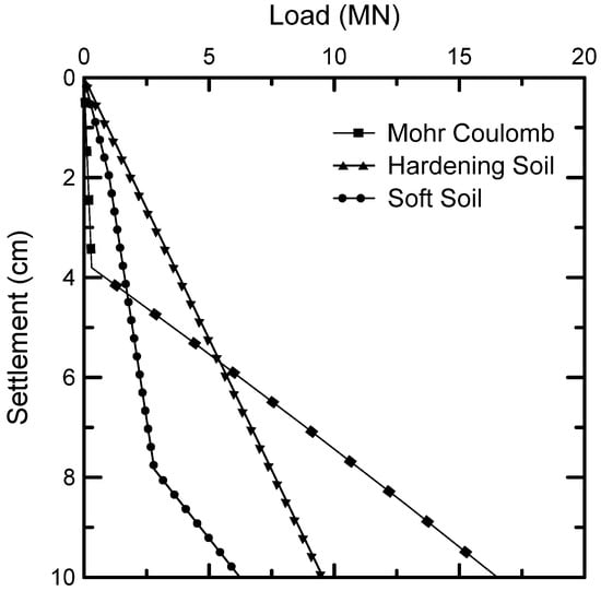
Figure 4.
Load-settlement curves for the shallow cylindrical raft foundation and the 10 cm serviceability limit.
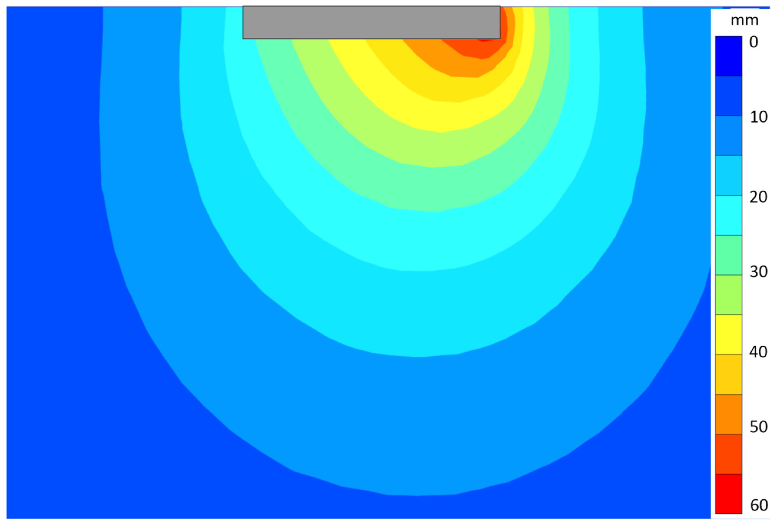
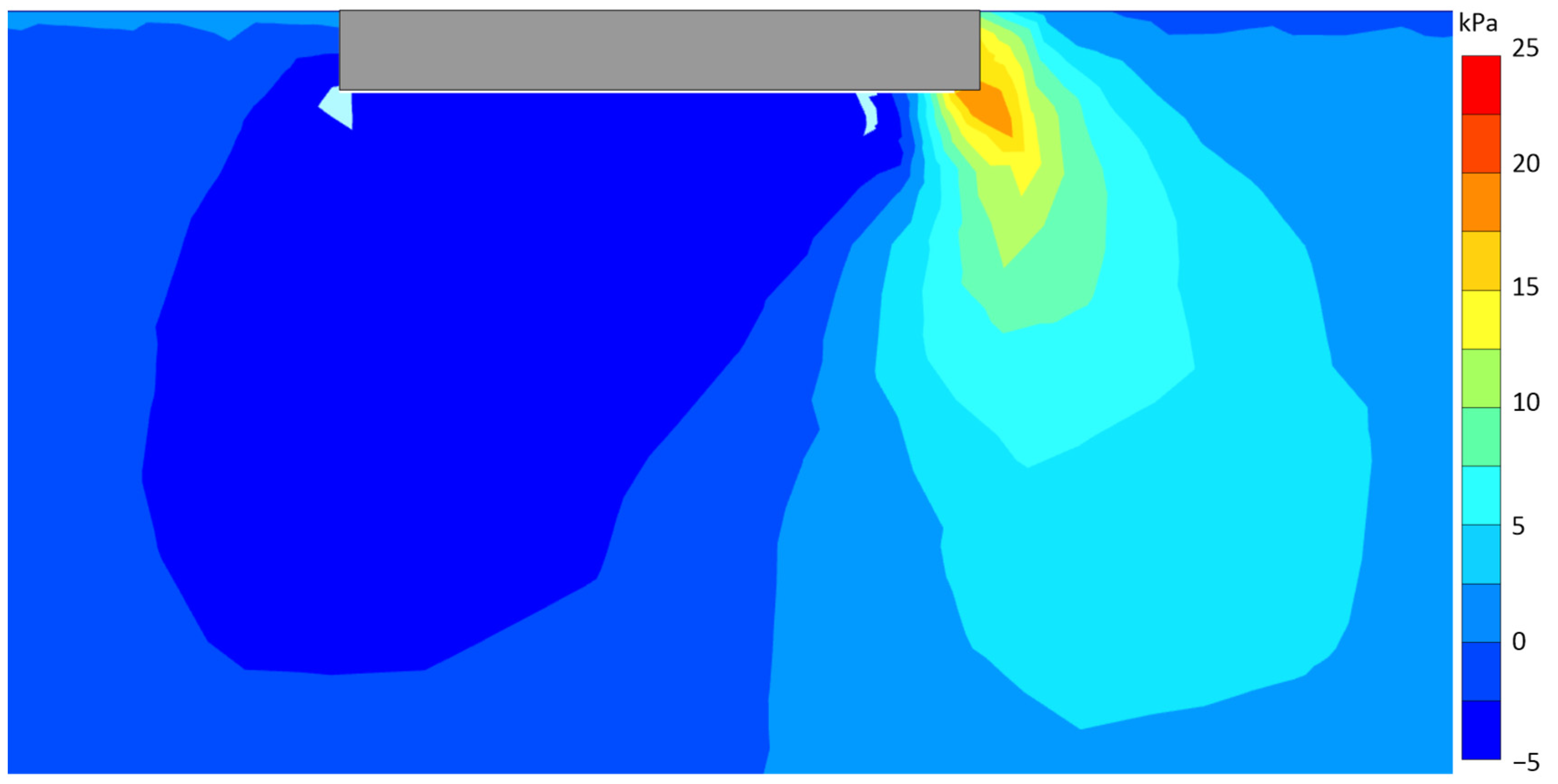
After computing the maximum vertical load, the foundation was examined for combined vertical load Q and bending moment M. Initially, the foundation was subjected to a vertical load (smaller than the maximum allowed). Then a bending moment was applied to reach the 0.1° rotation. An empirical procedure was followed to find the bending moment that caused this rotation angle based on the rigid foundation’s response. The accuracy of the relationship between the rotation and the bearing moment was further validated by applying the rotation separately as a boundary condition and obtaining the same result. Figure 5 presents the soil displacements for the Mohr–Coulomb model when the foundation was subjected to a 1 MN vertical load and a 35 MN-m bending moment (approximately 0.1° of rotation). The maximum settlement of approximately 6 cm corresponds to the edge of the footing. Additionally, Figure 6 illustrates the shear stresses for the same conditions. Similarly, the maximum shear stress is at the edge of the footing, where plasticity has been developed.

Figure 5.
Cross-section on the xz plane showing the settlements for vertical load 1 MN and bending moment 35 MN-m (approximate rotation 0.1°) using the Mohr–Coulomb model.

Figure 6.
Cross-section on the xz plane showing the shear stresses for vertical load 1 MN and bending moment 35 MN-m (approximate rotation 0.1°) using the Mohr–Coulomb model.
The serviceability envelope was created by the bending moment, and vertical load combinations that produced rotations and settlements less than the constraints discussed previously (Figure 7). By comparing these results with the typical medium-size wind turbine loads, it is concluded that shallow raft foundations are not a practical solution to the installation of wind turbines on this material. The allowed loading combinations based on the numerical analysis do not include medium-sized wind turbine typical loads. The critical problem is primarily with the bending moment. Moments up to 40 MN-m are acceptable according to the widest envelope (Mohr–Coulomb), while for the other two constitutive models, the respective value is of the order of 25–30 MN-m.
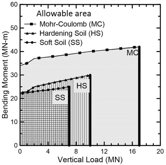
Figure 7.
Serviceability limit envelopes for the shallow cylindrical raft foundation on the spoil heap.
Nevertheless, the moments of a medium-sized wind turbine are 60 MN-m at the very least. The leading cause of this inadequacy is the insufficient rotational stiffness of the spoil, as expressed in Equation (1). In this spoil heap case, two alternatives are possible. Smaller size wind turbines appear to be feasible to be founded as examined, but a lower energy production should be expected in this case. Moreover, more complex foundation systems (deep foundations) should be used if medium-sized or larger wind turbines are to be used for energy production.
3.2. Building Installation with Isolated Footings
Towards the exploitation of the spoil areas to produce and store energy, there is a need for supportive facilities, mainly in buildings such as offices or warehouses. Even the installation of these constructions can be troublesome in the present case, provided the spoil’s nature and geotechnical response. Small buildings typically employ shallow footings, with each footing bearing a vertical load (self-weight of the construction elements) and a bending moment (eccentricity) from the superstructure. To determine the spoil material’s capacity for this reclamation type, similarly to the previous case, a serviceability limit envelope in terms of vertical load (Q) and bending moment (M) is used. Combinations of forces and moments lying inside the envelope are acceptable, while those lying outside are not.
Initially, the footing’s area and shape are decided, and its dimensions are tentatively selected. Typically, the design’s goal is to determine the dimensions of the footing. However, the footing dimensions are preliminarily estimated herein as the focus is to assess the potential of supportive buildings’ installation. For that purpose, the mean stress developed below the foundation is used and compared with the maximum allowable value qmax. A geotechnical study at the specific site should define this maximum allowable stress. However, as such a task is inefficient for small projects, standards and regulations provide typical qmax values based on soil classification.
The present spoil is a chaotic mix of several materials, primarily high plasticity silts and clays, denoting qmax < 75 kPa for such materials [32]. A conservative value of 50 kPa is assumed due to the spoil’s geotechnical uncertainty. Based on typical assumptions for buildings, the vertical load per story equals 300 kN [26], and assuming a regular 2-story building, the vertical load is Q = 600 kN. This load is multiplied by a factor of 2, leading to the final presumed load for the footing of Qd = 1.2 MN. Therefore, the footing’s area A equals 24 m2 (qmax = Qd/A), based on the vertical load and the maximum allowable stress.
Shallow building footings are commonly rectangular due to the ease of construction. Thus, the footing was chosen to be square with dimensions B = L = 5 m. The footing thickness is chosen to be 0.80 m for practical purposes. This footing is relatively large compared to standard sizes because the material under investigation is relatively soft, and smaller footings would lead to unacceptable settlements.
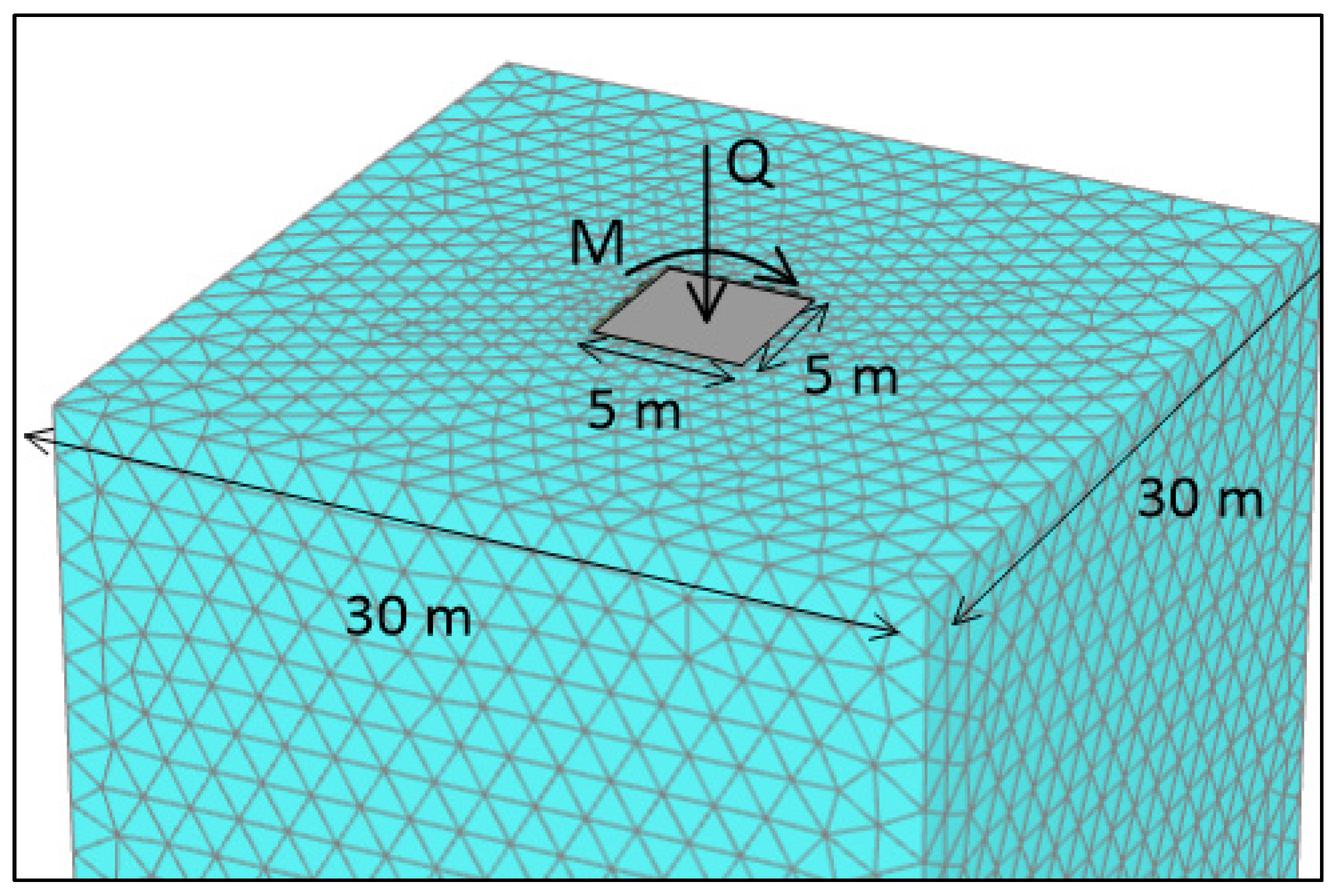
A 3D finite element analysis was employed to create the limit envelope due to the 3D geometry of the footing and the non-symmetric loading type. A building has several footings, but each is assumed to be isolated for simplicity and without losing generality, as different footings are far enough to prevent interaction. A single footing was analyzed, simulated as a rigid body in that vein. Triangular 10-noded elements were used, and the finite element mesh was appropriately chosen to minimize boundary effects. The average spoil material properties were used to obtain an average response. The footing was placed on the grid’s center, fully embedded in its depth of 0.80 m, and the mesh was refined around the footing. Figure 8 shows an overview of the 3D discretization of the finite element model.
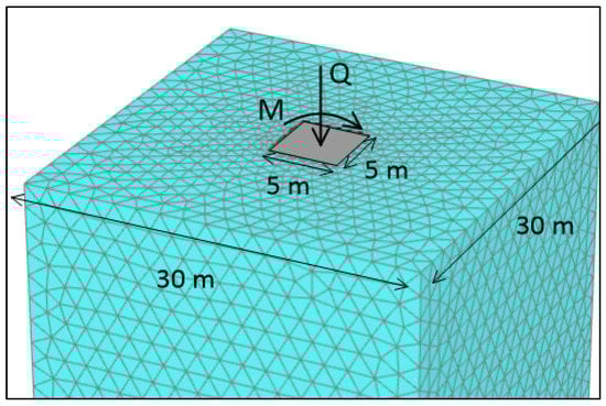
Figure 8.
Finite element discretization and a schematic view of the embedded square footing.
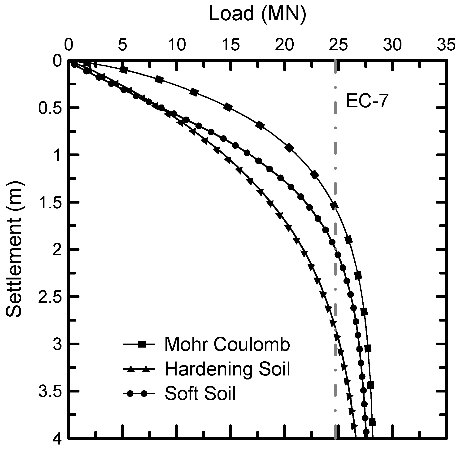
Initially, the load-displacement curve of the footing was obtained. Figure 9 shows the soil’s response to the three constitutive models mentioned in Section 2. Although the footing’s bearing capacity is relatively high, the settlements are enormous. The three constitutive models show similar results with major differences referring to the emerging settlements. The Mohr–Coulomb model exhibits considerably lower settlements compared to the other two models throughout the range of loads. The Hardening Soil and Soft Soil initially (for small loads) behave similarly, but for larger loads (>10 MN), the Hardening Soil exhibits larger settlements. The bearing capacity was also calculated using the relationships of the Eurocode-7 [31] equal to 24.7 MN, slightly less than the numerical values.

Figure 9.
Load settlement curve and bearing capacity of the square footing on the spoil heap.
Similar to the previous section, constraints are related to the footing’s displacements. Specifically, two criteria are set to create the limit envelope, referring to the allowable eccentricity and the settlements. The footing could exhibit eccentricity in both directions, but this is unfavorable and commonly avoided. By definition, the footing eccentricity is the ratio of the bending moment over the vertical load e = M/Q. The maximum allowed eccentricity must not exceed 1/6 of the footing width to prevent the formation of a gap between soil and foundation. Therefore, the eccentricity limit line is defined by e = M/Q = 5/6 m (the foundation width is B = 5 m).
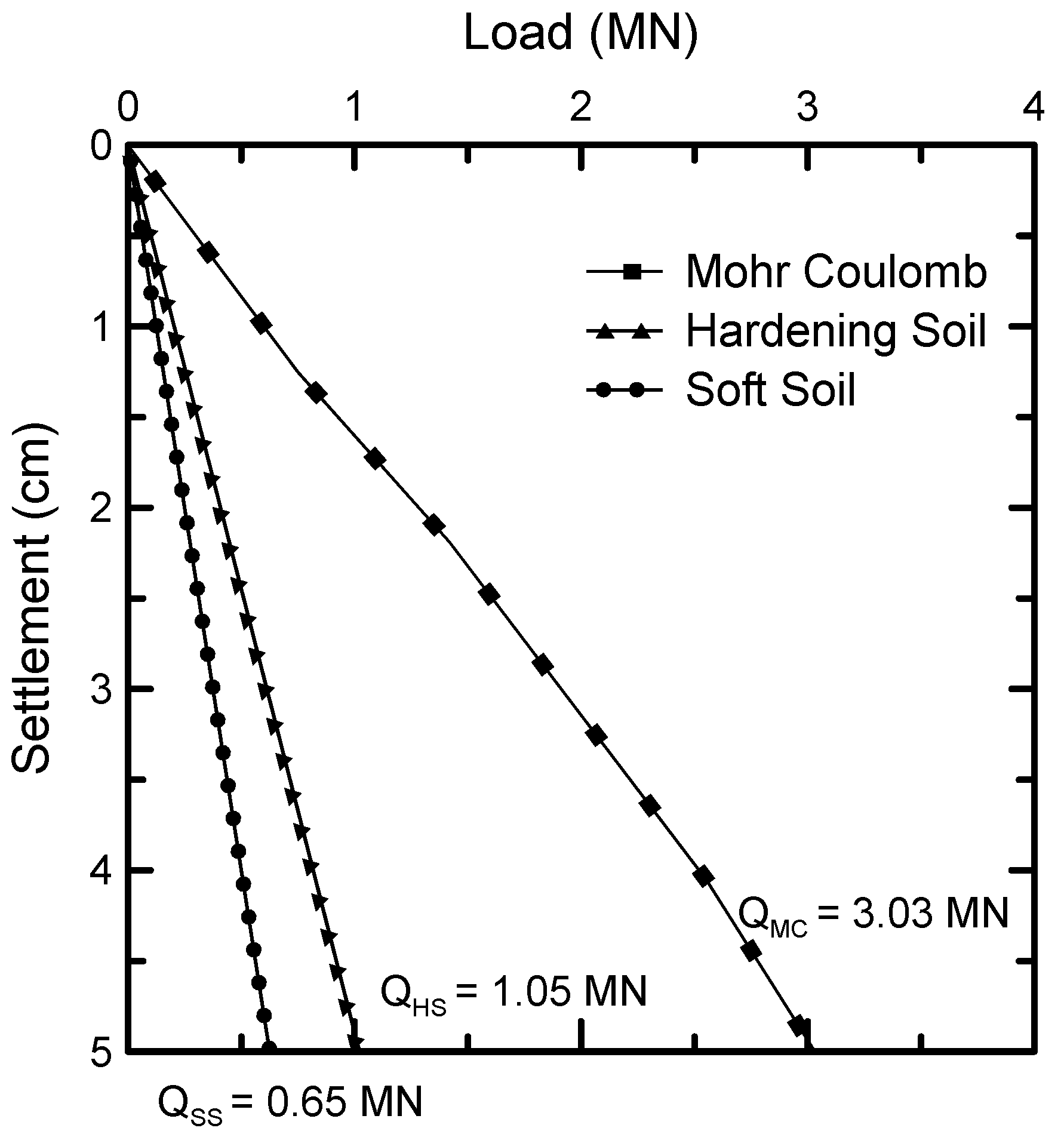
Moreover, according to Eurocode-7 [29], settlements up to 5 cm are acceptable for structures founded on isolated footings. The 5 cm is a typical limit value [33] larger than the 2.5 cm limit value also used for the allowable settlements of isolated footings, e.g., see [26,34]. The 3D finite element analysis described above was employed to obtain the vertical load corresponding to a 5 cm settlement. When the settlement reaches 5 cm, the corresponding vertical loads are marked in Figure 10: QMC = 3.03 MN for the Mohr–Coulomb, QHS = 1.05 MN for the Hardening Soil, and QSS = 0.65 MN for the Soft Soil model. These differences are pretty significant due to the differences in the elasto-plastic behavior of the models (see Figure 1). According to the Mohr–Coulomb model, the spoil can bear the typical loads of a 2-story building. On the other hand, based on the Hardening Soil and Soft Soil models, the spoil material can bear significantly smaller loads corresponding to generally smaller structures (e.g., single-story buildings or a small warehouse).

Figure 10.
Load-settlement curve for the square footing and the 5 cm serviceability limit.
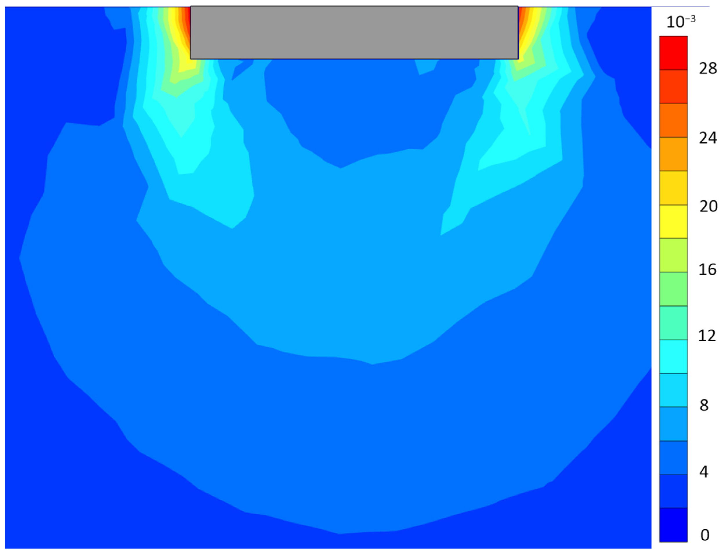
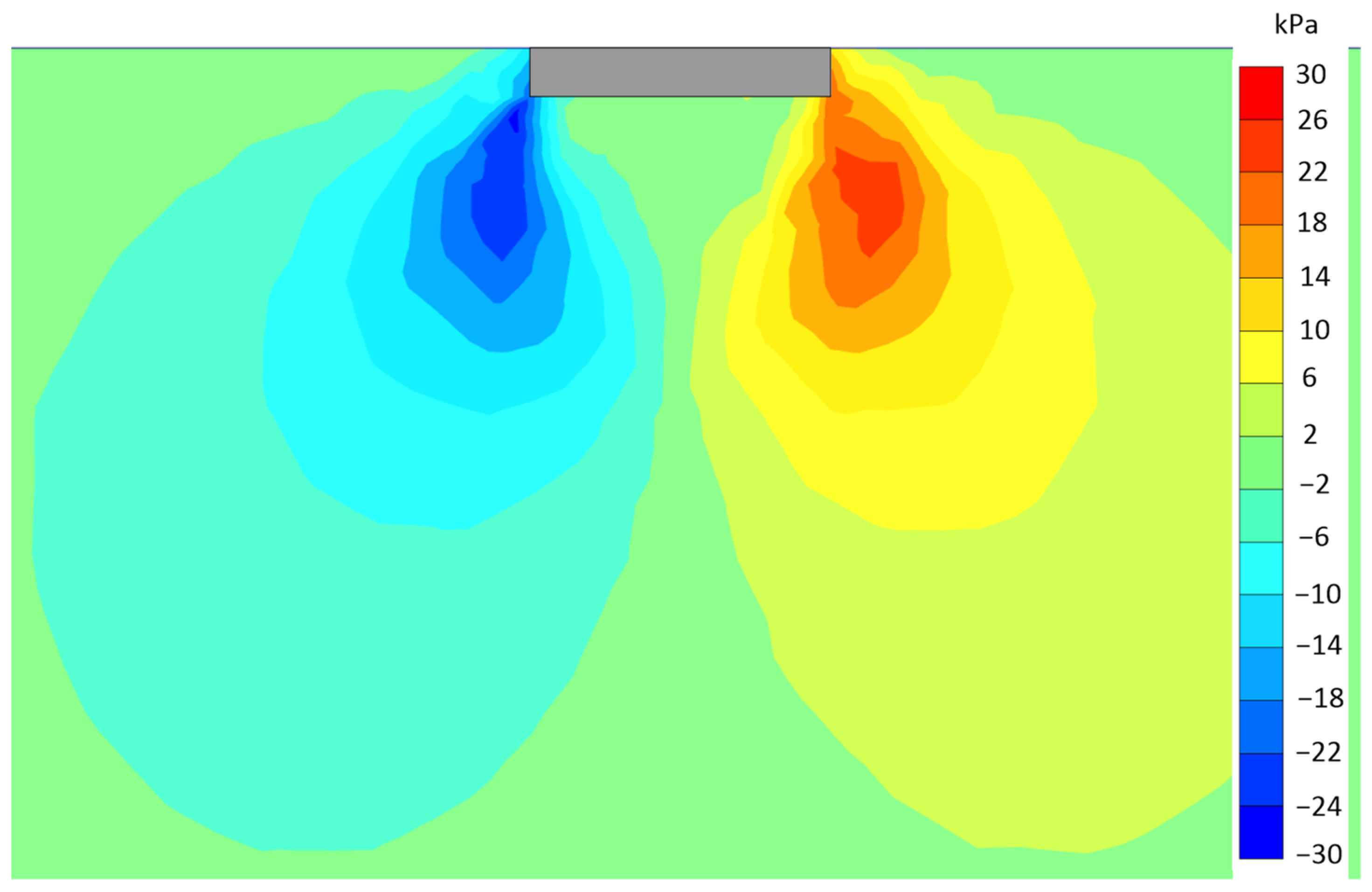
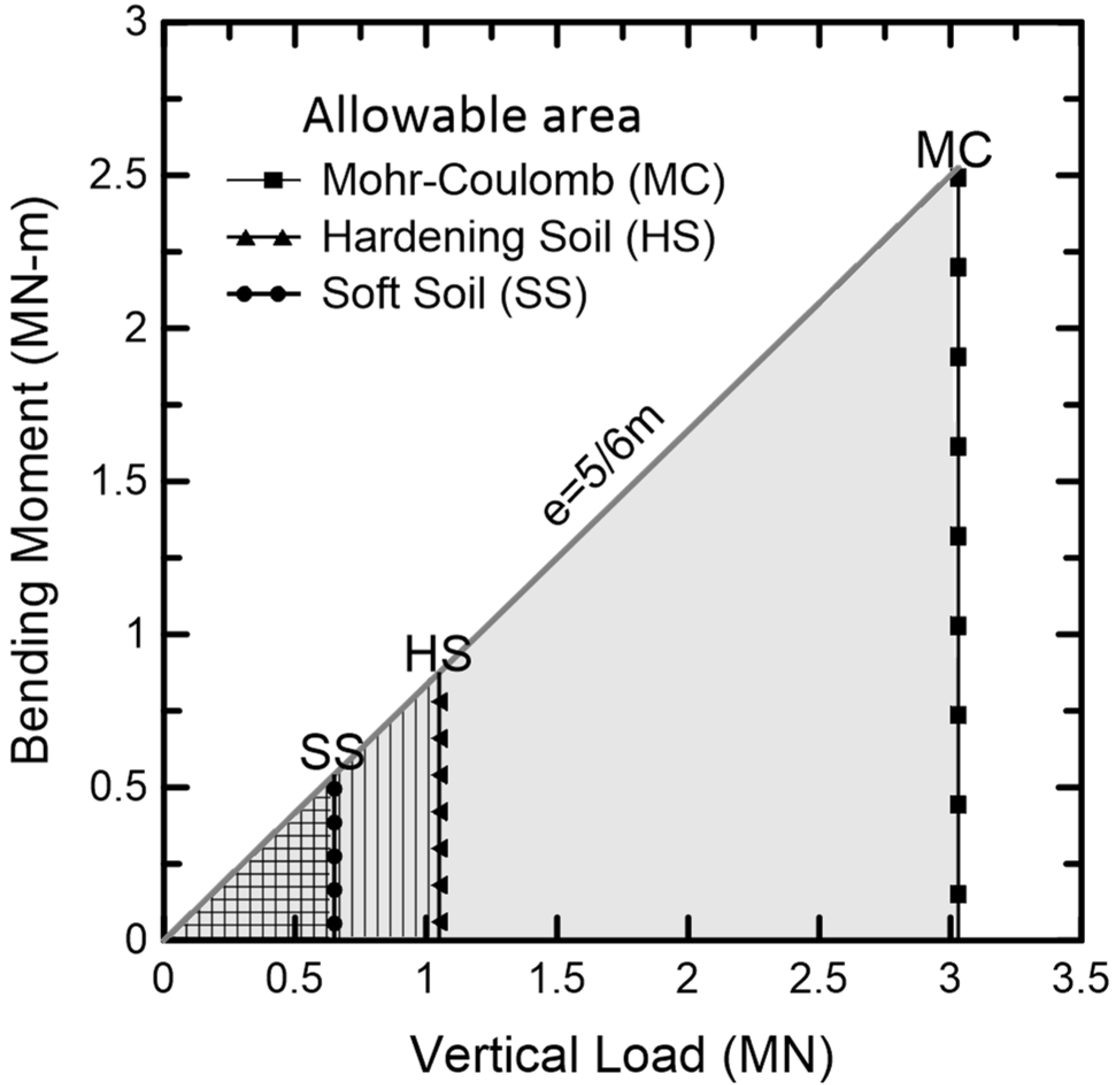
Figure 11 and Figure 12 present the response of the soil in terms of shear strains and shear stresses at the limit of 5 cm settlement. The soil has already been plasticized under the footing for a depth of approximately B. The shear stresses (for values more than 10 kPa) expand at a depth similar to the one indicated by the plastic points (not presented herein). The two criteria defined above—eccentricity and settlement—define the serviceability constraints. They were translated in vertical load and bending moment to obtain a force-moment limit envelope. The vertical load Q must be lower than the maximum (depending on the constitutive model), and the M-Q combination must lie below the eccentricity limit line. Therefore, the serviceability envelopes are enclosed by the eccentricity limit line and the vertical line corresponding to the maximum load of each constitutive model. Figure 13 presents the three envelopes for the three constitutive models; the eccentricity limit line is defined by e = M/Q = 5/6 m, denoting a linear increase in the maximum bending moment with the vertical force.
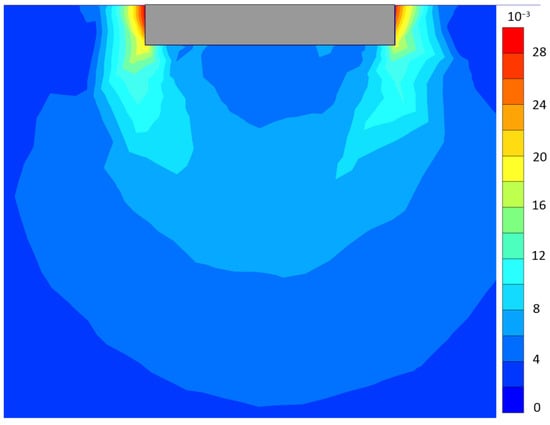
Figure 11.
Cross-section on the xz plane showing the shear strains for the 5 cm serviceability limit using the Mohr–Coulomb model.
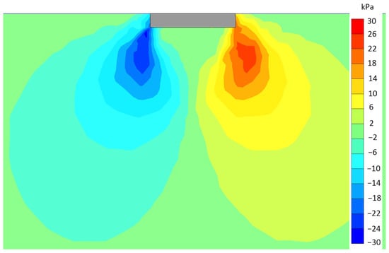
Figure 12.
Cross-section on the xz plane showing the shear stresses for the 5 cm serviceability limit using the Mohr–Coulomb model.

Figure 13.
Serviceability envelopes for the square footing on the spoil heap.
In this case, the decision on the constitutive model crucially affects the results. Compared with the typical loads of small buildings (Qd ≈ 1–2 MN), the Mohr–Coulomb model provides acceptable results (QMC = 3.03 MN). The Hardening Soil envelope barely includes loading combinations (QHS = 1.05 MN) for 2-story buildings but can be used as foundation soil for smaller buildings. The Soft Soil envelope includes even less favorable combinations (QSS = 650 kN) corresponding to small warehouses or offices. Overall, the fundamental problem of the spoil is the small stiffness that leads to large settlements for relatively small vertical loads.
4. Conclusions
Extensive coal and lignite mining led to massive spoil heaps from the excavated overburden material. The efficient reclamation of these vast areas is a top priority and a challenging subject globally. In this work, alternatives were examined regarding the reclamation of a massive spoil heap to serve as a reference for other cases. They specifically involved the installation of a wind turbine by a raft foundation or the foundation of supportive buildings by isolated footings. As the geotechnical issues are often critical to the valorization of these areas, they have been deeply investigated in this study. Three constitutive models calibrated on experimental data were used to evaluate their effect on the results.
Initially, the foundation of wind turbines with a shallow cylindrical raft was evaluated by employing 3D finite element analysis. Based on the analysis, a limit envelope was created denoting the acceptable loading combinations on the spoil and was compared to typical loads from medium-sized wind turbines. The comparison shows that the shallow foundation is not adequate for this type of gigantic installation. Wind turbines are subjected to large vertical loads and vast overturning moments, resulting in large settlements and rotations much higher than the acceptable limits.
Another investigated alternative was isolated footings, the primary building installation method, again analyzed with 3D finite elements. The material’s capabilities were determined in vertical load and bending moment within the constraints that ensure the construction’s safety and serviceability with the three constitutive models. The serviceability limit envelope was constructed, defining the acceptable loading combinations—for the three soil models—and was compared with typical loads. The three constitutive models provided different results in terms of acceptable loading combinations. The Mohr–Coulomb envelope included the typical 2-story buildings, while the Hardening Soil envelope barely included them, and the Soft Soil envelope included only much smaller structures. The major problem is the enormous settlements that emerged for relatively small loads, which would damage the superstructure long before the footing reached its bearing capacity.
Overall, the considered spoil material is generally inadequate as soil for shallow foundations. Ground improvement techniques must be implemented since the spoil has low stiffness and strength due to its creation and nature. An alternative foundation type, a cylindrical raft with piles, appears to be the only possible scenario for a wind turbine. Finally, further studies and on-site tests should be conducted to understand the spoil material’s nature and behavior better and quantify its response to different loading conditions (e.g., cyclic loading).
Author Contributions
Conceptualization, A.I.T., I.E.Z. and N.C.K.; methodology, A.I.T. and I.E.Z.; formal analysis, A.I.T.; software, A.I.T.; validation, I.E.Z. and A.I.T.; writing—original draft preparation, A.I.T.; writing—review and editing, A.I.T., I.E.Z., C.R. and N.C.K.; visualization, A.I.T. and I.E.Z.; supervision, I.E.Z. and N.C.K.; project administration, I.E.Z. and N.C.K.; funding acquisition, I.E.Z. and N.C.K. All authors have read and agreed to the published version of the manuscript.
Funding
This work has received funding from the European Union’s Research Fund for Coal and Steel under the project SUMAD grant agreement No 847227. Financial assistance by the European Commission is much appreciated.
Data Availability Statement
Not applicable.
Acknowledgments
The authors are thankful to Ioannis Tiptiris, Civil Engineer, for his contribution to the initial part of this work.
Conflicts of Interest
The authors declare no conflict of interest.
References
- BP. BP Statistical Review of World Energy; BP: London, UK, 2021. [Google Scholar]
- Masoudian, M.S.; Zevgolis, I.E.; Deliveris, A.V.; Marshall, A.M.; Heron, C.M.; Koukouzas, N.C. Stability and characterisation of spoil heaps in European surface lignite mines: A state-of-the-art review in light of new data. Environ. Earth Sci. 2019, 78, 505. [Google Scholar] [CrossRef] [Green Version]
- Ichrak, H.; Mostafa, B.; Abdelkabir, M.; Bruno, B. Effect of cementitious amendment on the hydrogeological behavior of a surface paste tailings’ disposal. Innov. Infrastruct. Solut. 2016, 1, 19. [Google Scholar] [CrossRef] [Green Version]
- Hodačová, D.; Prach, K. Spoil heaps from brown coal mining: Technical reclamation versus spontaneous revegetation. Restor. Ecol. 2003, 11, 385–391. [Google Scholar] [CrossRef]
- Hendrychová, M.; Šálek, M.; Tajovský, K.; Řehoř, M. Soil Properties and Species Richness of Invertebrates on Afforested Sites after Brown Coal Mining. Restor. Ecol. 2012, 20, 561–567. [Google Scholar] [CrossRef]
- Spears, D.A. Environmental impact of minerals in UK coals. Geol. Soc. Spec. Publ. 1997, 125, 287–295. [Google Scholar] [CrossRef]
- Kasztelewicz, Z. Approaches to Post-Mining Land Reclamation in Polish Open-Cast Lignite Mining. Civ. Environ. Eng. Rep. 2014, 12, 55–67. [Google Scholar] [CrossRef] [Green Version]
- Alves Dias, P.; Kanellopoulos, K.; Medarac, H.; Kapetaki, Z.; Miranda-Barbosa, E.; Shortall, R.; Czako, V.; Telsnig, T.; Vazquez-Hernandez, C.; Lacal Arántegui, R.; et al. EU Coal Regions: Opportunities and Challenges Ahead—EUR 29292 EN; Publications Office of the European Union: Luxembourg, 2018. [Google Scholar]
- Skinner, H.D.; Watts, K.S.; Charles, J.A. Building on colliery spoil: Some geotechnical considerations. Ground Eng. 1997, 30, 35–40. [Google Scholar]
- Hegde, A.; Das, T. Finite element-based probabilistic stability analysis of rock-fill tailing dam considering regional seismicity. Innov. Infrastruct. Solut. 2019, 4, 37. [Google Scholar] [CrossRef]
- Steiakakis, E.; Kavouridis, K.; Monopolis, D. Large scale failure of the external waste dump at the “South Field” lignite mine, Northern Greece. Eng. Geol. 2009, 104, 269–279. [Google Scholar] [CrossRef]
- Ulusay, R.; Arikan, F.; Yoleri, M.F.; Çaǧlan, D. Engineering geological characterization of coal mine waste material and an evaluation in the context of back-analysis of spoil pile instabilities in a strip mine, SW Turkey. Eng. Geol. 1995, 40, 77–101. [Google Scholar] [CrossRef]
- Kasmer, O.; Ulusay, R.; Gokceoglu, C. Spoil pile instabilities with reference to a strip coal mine in Turkey: Mechanisms and assessment of deformations. Environ. Geol. 2006, 49, 570–585. [Google Scholar] [CrossRef]
- Okagbue, C.O. The geotechnical characteristics and stability of a spoil heap at a southwestern pennsylvania coal mine, U.S.A. Eng. Geol. 1984, 20, 325–341. [Google Scholar] [CrossRef]
- Ashfaq, M.; Heeralal, M.; Moghal, A.A.B. Characterization studies on coal gangue for sustainable geotechnics. Innov. Infrastruct. Solut. 2020, 5, 15. [Google Scholar] [CrossRef]
- Zevgolis, I.E.; Theocharis, A.I.; Deliveris, A.V.; Koukouzas, N.C.; Roumpos, C.; Marshall, A.M. Geotechnical Characterization of Fine-Grained Spoil Material from Surface Coal Mines. J. Geotech. Geoenviron. Eng. 2021, 147, 04021050. [Google Scholar] [CrossRef]
- Euracoal. EURACOAL Market Report 1/2018–5/2018; European Association for Coal and Lignite: Brussels, Belgium, 2018. [Google Scholar]
- Roumpos, C.; Pavloudakis, F.; Liakoura, A.; Nalmpanti, D.; Arampatzis, K. Utilisation of Lignite Resources within the Context of a Changing Electricity Generation Mix. In Proceedings of the 10th Jubilee International Brown Coal Mining Congress, Bełchatów, Poland, 16–18 April 2018; pp. 355–365. [Google Scholar]
- Bentley Systems. 3D Finite Element Geotechnical Analysis Software—Plaxis3D v.2018; Bentley Systems: Dublin, Ireland, 2018. [Google Scholar]
- Theocharis, A.I.; Zevgolis, I.E.; Koukouzas, N.C. Validation of constitutive models for spoil material of brown coal mines. In Proceedings of the 3rd Conference of the Arabian Journal of Geosciences (CAJG), Sousse, Tunisia, 2–5 November 2020. [Google Scholar]
- Grünberg, J.; Göhlmann, J. Concrete Structures for Wind Turbines, 1st ed.; Bergmeister, K., Fingerloos, F., Wörner, J.-D., Eds.; Ernst & Sohn: Hoboken, NJ, USA, 2013. [Google Scholar]
- Shrestha, S.; Ravichandran, N.; Rahbari, P. Geotechnical design and design optimization of a pile-raft foundation for tall onshore wind turbines in multilayered clay. Int. J. Geomech. 2018, 18, 04017143. [Google Scholar] [CrossRef]
- Shrestha, S.; Ravichandran, N. Performance- and cost-based robust design optimization procedure for typical foundations for wind turbine. Int. J. Geotech. Eng. 2020, 14, 395–408. [Google Scholar] [CrossRef]
- Mohamed, W.; Austrell, P.E. A comparative study of three onshore wind turbine foundation solutions. Comput. Geotech. 2018, 94, 46–57. [Google Scholar] [CrossRef]
- Baniotopoulos, C.; Borri, C.; Stathopoulos, T. Environmental Wind Engineering and Design of Wind Energy Structures; Springer: Vienna, Austria, 2011; Volume 531. [Google Scholar]
- Salgado, R. The Engineering of Foundations; McGraw-Hill: Boston, MA, USA, 2008. [Google Scholar]
- DNV-Riso. Guidelines for the Design of Wind Turbines; Det Norske Veritas, Copenhagen and Wind Energy Department, Risø National Laboratory: Copenhagen, Denmark, 2002; Volume 2. [Google Scholar]
- Papagiannis, M. Wind Turbine Foundations in Clay: Technical and Economic Considerations for Proposals for Wind Turbine Foundations; Uppsala University: Uppsala, Sweden, 2018. [Google Scholar]
- European Union. EN 1997-1 (English): Eurocode 7: Geotechnical Design—Part 1: General Rules (Annex H); The European Union: Brussels, Belgium, 2004. [Google Scholar]
- European Union. EN 1997-1 (English): Eurocode 7: Geotechnical Design—Part 1: General Rules; The European Union: Brussels, Belgium, 2004. [Google Scholar]
- European Union. EN 1997-1 (English): Eurocode 7: Geotechnical Design—Part 1: General Rules (Annex D); The European Union: Brussels, Belgium, 2004. [Google Scholar]
- BS:8004; British Standards: Code of Practise for Foundations. British Standards: London, UK, 1986.
- Skempton, A.W.; Macdonald, D.H. The allowable settlements of buildings. Proc. Inst. Civ. Eng. 1956, 5, 727–768. [Google Scholar] [CrossRef]
- Terzaghi, K.; Peck, R.B. Soil Mechanics in Engineering Pratice, 2nd ed.; John Wiley: New York, NY, USA, 1967. [Google Scholar]


Publisher’s Note: MDPI stays neutral with regard to jurisdictional claims in published maps and institutional affiliations. |
© 2022 by the authors. Licensee MDPI, Basel, Switzerland. This article is an open access article distributed under the terms and conditions of the Creative Commons Attribution (CC BY) license (https://creativecommons.org/licenses/by/4.0/).