Article

Research on Multi-Mode Drive Optimization Control Strategy of Four-Wheel-Drive Electric Vehicles with Multiple Motors

1
School of Mechanical and Electrical Engineering, Xi’an University of Architecture and Technology, Xi’an 710055, China
2
National Engineering Research Center of Electric Vehicles, Beijing Institute of Technology, Beijing 100081, China
3
Jianglu Machinery and Electronics Group Co., Ltd., Xiangtan 411199, China
*
Authors to whom correspondence should be addressed.
Sustainability 2022, 14(12), 7378; https://doi.org/10.3390/su14127378
Submission received: 15 May 2022 / Revised: 12 June 2022 / Accepted: 14 June 2022 / Published: 16 June 2022

Abstract

:
Four-wheel-drive electric vehicles with multiple motors have several advantages such as energy saving, environmental protection, and excellent dynamics performance. Therefore, they have become an important development trend in the field of electric vehicles in the past few years. To deal with the problems of the economy and dynamics optimization of an electric vehicle with dual motors on the front axle and a single motor on the rear axle, a multi-mode drive optimization control strategy based on the hierarchical control architecture is proposed in this paper. In the strategy, the reference torque distribution strategy of the front and rear motors is obtained by optimizing the instantaneous energy consumption power in the economy module, and a torque compensation strategy is formulated based on the fuzzy control in the dynamics module to improve the vehicle dynamics in high dynamics demand conditions. Finally, the closed-loop cycle test and the driver-in-the-loop test are carried out to verify the performance of the strategy proposed in this paper, and the results show that energy consumption is reduced by 6.45% in the World Harmonized Light-duty Vehicles Test Cycle (WLTC), and that vehicles accelerate more quickly in variable acceleration conditions under the proposed strategy.

1. Introduction

As global energy and environmental crises are aggravated by the fact that traditional vehicles consume large amounts of fossil fuels, electric vehicles have been rapidly developed worldwide [1,2]. In particular, due to the easily extensible structure, easy-to-implement layout, and precise control of the motor, four-wheel-drive electric vehicles with multiple motors composed of two or more motors have notable advantages in vehicle dynamics, economy, and reliability compared with traditional fuel vehicles [3,4]. Hence, they are widely used by many classic electric vehicles such as Tesla Model S and BYD Han, and have also become an important development trend in electric vehicles [5]. However, multi-motor electric vehicles have many problems, such as driving force distribution, multi-motor control, etc., which affect the energy consumption, vehicle dynamics, and vehicle stability [6,7]. Consequently, the drive control strategy is important in improving the performance of multi-motor electric vehicles.
The main advantage of multi-motor electric vehicles is that they can improve the vehicle dynamics performance and drive system efficiency by optimizing the distribution of driving force [8]. Currently, the research methods on drive control optimization of multi-motor driven electric vehicles can be roughly divided into two categories:
  • The first category of research methods is based on physical models of the drive system. For example, Li Liang established the efficiency loss model of the in-wheel motor under consideration of the iron loss, then obtained the optimized motor torque distribution by identifying the parameters of the motor online based on the MAR theory, thereby improving the energy utilization efficiency of the vehicle [9]. Yuan Xi-bo studied the torque distribution of the front and rear motors at different vehicle velocities based on the loss model of the dual-motor drive system and verified the performance of the control strategy through the motor test bench [10]. These types of methods mainly optimize the torque distribution of the drive system by the system loss model based on the physical characteristics of the motor and controller, so they can obtain accurate and reliable optimization results because the characteristics of the drive system are accurately described. However, due to the complex structure of the physical model and a large amount of calculation, the real-time performance of this research method is poor.
  • The second category is based on the efficiency map of the drive system. For instance, Pennycott Andrew optimized the steady-state and transient energy consumption of a dual-motor 4WD electric vehicle based on the motor efficiency loss map [11]. Yang Yee-Pien used the particle swarm algorithm to optimize the efficiency map of the driving motor of a 4WD electric vehicle, then established a real-time optimization allocation strategy of the driving torque, thereby effectively reducing the motor energy loss [12]. Wang Jun-min took the minimization of the weighted sum of the vehicle speed error and the power consumption of the actuators as the objective function, and globally optimized the torque distribution of the four wheels to reduce the power loss of the system for a 4WD electric vehicle [13]. Yu Zhuo-ping adopted the efficiency maximization method to optimize the torque distribution coefficient matrix of the 4WD electric vehicle, and the overall energy efficiency of the vehicle was improved by about 3% due to the reduction in the in-wheel motor heat generation and the increase in feedback braking energy recovery [14]. The methods of the second category mainly use the efficiency map of the motor or the drive system to optimize the torque distribution of the drive system. They have some advantages such as fast calculation speed and good real-time performance, which are easy to deploy in the real vehicle controller. However, since the motor efficiency map depends on the test calibration, the quality of the calibration data will have a significant impact on the control strategy.
Vehicle drive control involves many factors, such as vehicle operating state and the driver’s driving intention [15]; as a consequence, researchers have studied the optimization of drive control strategy with comprehensive consideration of these factors. Qin Da-tong corrected the driving torque under high power demand conditions such as vehicle acceleration by using fuzzy recognition of driving intentions, and eventually improved the vehicle dynamics [16]. According to the accelerator pedal displacement and motor speed, Wang Jia proposed a fuzzy control strategy of the motor torque for three driving modes, thereby optimizing the vehicle performance [17]. Furthermore, in terms of driving, the multi-motor electric vehicle has the additional degrees of freedom in torque vectoring for stable vehicle maneuverability and better fault tolerance; hence, this vehicle has been increasingly studied and commercially applied in recent years. Yi-Hsiang Tseng proposed a torque and battery distribution strategy to save energy and obtained a better travel distance and higher energy consumption efficiency [18]. Giovanni De Filippis analyzed the potential energy efficiency benefits from the understeer characteristics and wheel torque control allocation through experiments, and proposed a Control Allocation strategy to achieve an energy-efficient wheel torque distribution generating the reference yaw moment and wheel torque [19]. Ziyou Song proposed a general method called “equivalent loss strategy” to maximize the drivetrain efficiency for EVs with multi-PMSMs, and used a dynamic programming approach to minimize acceleration duration and energy consumption [20].
For four-wheel-drive electric vehicles with multiple motors, there are usually three drive modes: the front motor individually driving mode, the rear motor individually driving mode, and all motors simultaneously driving mode. However, as the front or rear motor individually driving mode can meet the total driving power requirements under certain driving conditions, it is able to reduce the power loss of the drive system due to the reduction in the working motor numbers, and at the same time improve the efficiency and economy of the electric drive system [21]. As a result, the method to find the optimal driving mode is the primary problem to solve for the drive optimization control of multi-motor-driven electric vehicles. In addition, as for the all motors simultaneously driving mode, due to the instantaneous changes in the vehicle states such as load, vehicle velocity, axle-to-load ratio, and so on, the required driving torque of the vehicle and the wheel adhesion will also change, and eventually, the torque distribution ratio between the front and the rear motor will affect the vehicle dynamics and the efficiency of the drive system. Hence, how to optimize the torque distribution ratio of the front and rear axle motors is also a significant research direction for the drive control of multi-motor electric vehicles.
Since four-wheel-drive electric vehicles are usually used in urban settings, the dynamics requirements are not particularly high most of the time. On the contrary, given the limited mileage and the long charging time caused by the bottleneck of battery technology, the optimization of economy performance has been becoming an important concern of drive control for four-wheel-drive electric vehicles in recent years. However, many investigations still put vehicle dynamics as the primary optimization task, like conventional fuel 4WD vehicles, which lack adequate attention to economy optimization and are not exactly suitable for four-wheel-drive electric vehicles. In view of the above problems, in this paper, we primarily focus on the economy optimization by optimizing the torque distribution ratio of each motor to reduce the instantaneous energy consumption, and then improve the vehicle dynamics through torque compensation under conditions requiring high power. The remainder of this paper is organized as follows: Section 2 introduces the strategy architecture of drive control and elaborates the principle and operation mechanism of the proposed control strategy; Section 3 elaborates the basic torque distribution strategy of the front and rear axle motors based on the optimization of instantaneous energy consumption power, which focuses on economy optimization; Section 4 introduces the torque compensation strategy based on fuzzy control under the condition of high power demand, which can improve the vehicle dynamics under the reference torque distribution on vehicle economy performance; Section 5 is the hardware-in-the-loop simulation and results analysis, which serves to verify the performance of the proposed drive control strategy; and Section 6 is the conclusion.

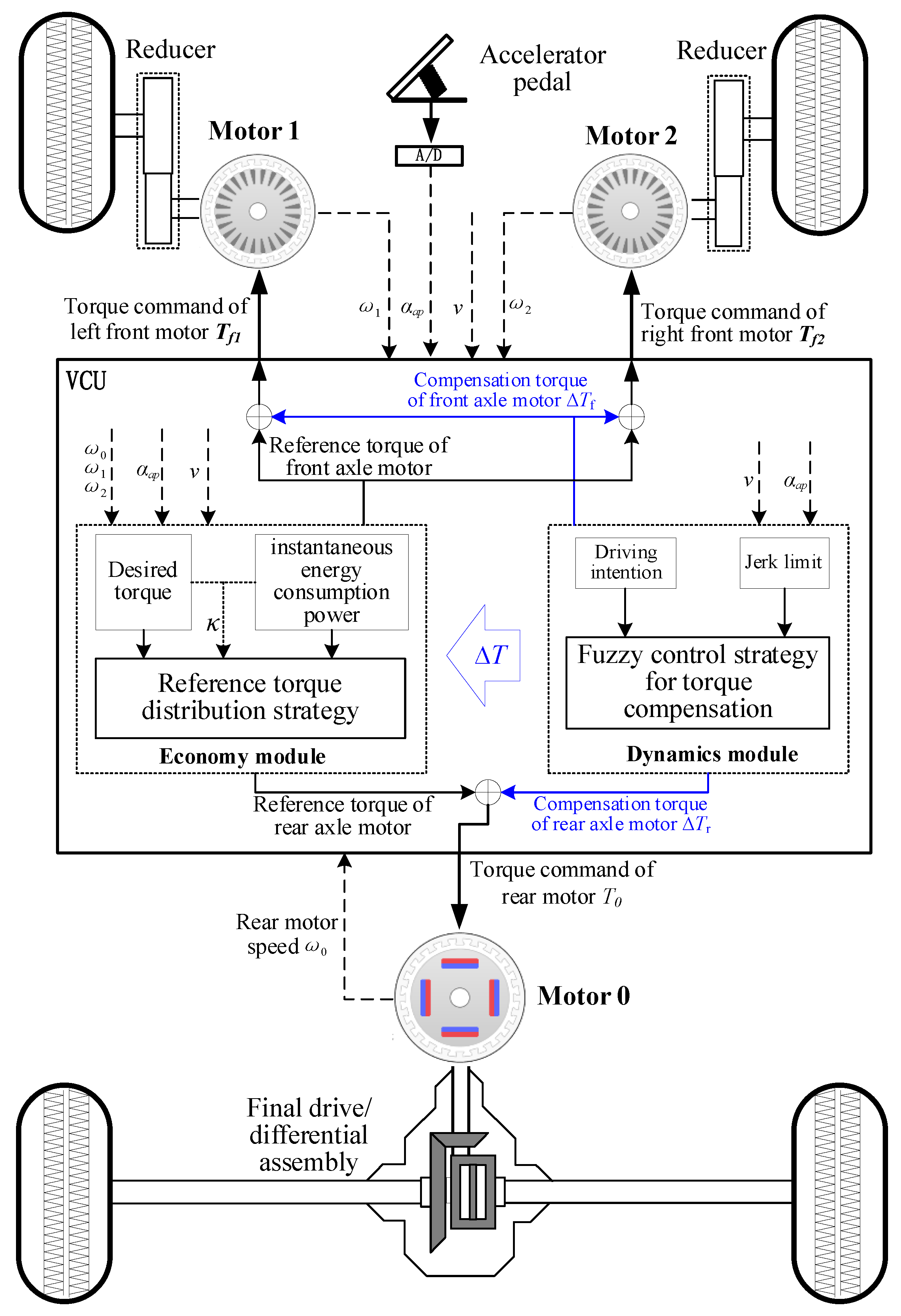
2. Architecture of Multi-Mode Drive Optimization Control Strategy for the Multi-Motor Electric Vehicle

The driving process of the vehicle can generally be divided into starting, slow acceleration, low-velocity cruise, normal acceleration, medium-velocity cruise, rapid acceleration, and high-velocity cruise. The required driving power is not high for the conditions such as slow acceleration, low-velocity cruise, normal acceleration, and medium-velocity cruise, so economy optimization focuses more on these conditions [22]. The required driving power under starting, rapid acceleration, and high-velocity cruise is greater; therefore, the optimization of vehicle dynamics mainly involves these conditions. The specific parameters of the vehicle and the motor studied in this paper are shown in Table 1. The drive system in this paper is composed of dual motors on the front axle and a single motor on the rear axle. Therein, the rear axle motor is used as the first power system, which is suited for urban conditions with low vehicle velocity. In contrast, the dual motors on the front axle are used as the second power system, suited for high power demand conditions with high velocity or middle/large acceleration to improve the high-velocity driving performance and acceleration performance.
According to the common driving state and the structural characteristics of the drive system analyzed in this paper, a driving control strategy composed of an economy control module and a dynamics control module is proposed to achieve the optimal economy and dynamics of the vehicle. The economy module mainly applies to the constant velocity condition or small acceleration condition. It is usually used to reduce the motor energy loss by optimizing the distribution of the motor torque, and the goal is to improve the energy utilization efficiency and prolong the driving range. The dynamics module mainly applies to the large power demand conditions such as starting or rapid acceleration, and it can quickly respond to the power demand by compensating the motor torque, thereby improving the vehicle dynamic performance of the vehicle. The specific architecture is shown in Figure 1.

3. Reference Torque Distribution Strategy for Front and Rear Axle Motors Based on Optimal Instantaneous Energy Consumption Power

The command of electric vehicle drive control comes from the driver’s manipulation of the accelerator pedal, and the driving torque command is mainly converted from the accelerator pedal opening. Therefore, the relationship between the original driving torque load coefficient and the accelerator pedal opening is as follows:
L d = f ( α a p )
where Ld is the torque load coefficient, which is determined by the relationship between the accelerator pedal opening and the external characteristics of the drive motor, and αap is the accelerator pedal opening in %. As a result, the initial demand torque of the multi-motor-driven electric vehicle in this paper is:
T i ( L d , n i ) = { L d T i max , n i n 0 i L d T i max L d n 0 i n i , n i > n 0 i , i = 0 , 1 , 2
where i is the number label of the motor, i = 0 represents the rear axle motor, i = 1 represents the left motor on the front axle, and i = 2 represents the right motor on the front axle; Ti(Ld,ni) is the torque of the i-th motor in N∙m; Timax is the peak torque of the i-th motor in N∙m; n0i is the base speed of the i-th motor in r/min; and ni is the speed of the i-th motor in r/min.
Consequently, the initially required torque of the vehicle at a certain accelerator pedal opening is:
T r e q = i = 0 2 T i ( L d , n i ) , i = 0 , 1 , 2
Hence, the total mechanical power of the vehicle drive motor can be obtained as:
P m e c h = i = 0 2 P m e c h , i = i = 0 2 ω i T i ( L d , n i ) , i = 0 , 1 , 2
where Pmech is the total mechanical power of the driving motor in kW, Pmech,i is the mechanical power of the i-th motor in kW, and ωi is the rotational speed of the i-th motor by international standards in rad/s:
ω i = 2 π n i 60 , i = 0 , 1 , 2
The total motor power should equal the sum of the motor mechanical part and the motor loss power:
P t = P m e c h + P l o s s = i = 0 2 ( P m e c h , i + P l o s s , i )
where Pt is the total power of the drive motor in kW, Ploss is the total loss of power of the drive motor in kW, and Ploss,i is the mechanical power of the i-th motor in kW; the motor loss power is mainly composed of iron loss, copper loss, and friction loss. The motor loss energy is dissipated into air in the form of heat. In motor mode, the motor power loss is:
P l o s s , i = { P m e c h , i ( 1 / η i ( T i , ω i ) 1 ) , T i > T i 0 , ω i > ω i 0 , i = 0 , 1 , 2 ω i 0 T i ( 1 / η i ( T i , ω i ) 1 ) , T i > T i 0 , 0 < ω i < ω i 0 , i = 0 , 1 , 2
where Ti0 and ωi0 are the torque and speed corresponding to the minimum data point of the i-th motor map characteristic, respectively, and ηi(Ti, ωi) is the efficiency of the i-th motor at a specific speed and torque, which is generally obtained through the motor calibration test.
It can be inferred from Equation (7) that for a four-wheel-drive electric vehicle that can be independently controlled by the front and rear motors, although the vehicle velocity and required torque at a certain time are determined, the motor loss power caused by the different torque distribution ratios of the front and rear motors is not the same. Therefore, by optimizing the torque distribution ratios, the motor working points will work in the high-efficiency area as much as possible, and eventually, the instantaneous energy consumption power will be improved, which can improve the vehicle economy effectively. Based on the ideas mentioned above, the rear motor drive torque distribution coefficient κ is used as the optimization variable in this paper, and the objective function equation obtained by the total power of each drive motor is as follows:
P t ( κ ) = ( 1 κ ) ω 1 T r e q i f + κ ω 0 T r e q i r + i = 0 2 P l o s s , i ( κ ) , i = 0 , 1 , 2
where κ is the torque distribution coefficient of the rear motor, and its value range is 0 ≤ κ ≤ 1. κ = 1 is the rear motor individually driving mode, κ = 0 is the front axle motor individually driving mode, and 0 < κ < 1 indicates all motors simultaneously driving mode. Pt(κ) is the total power of all drive motors under κ in kW; if and ir represent the front transmission and rear transmission ratio, respectively; and Ploss,i(κ) is the loss power of the i-th motor under κ in kW.
When optimizing the torque distribution, it should be ensured that the torque distributed to each motor does not exceed its maximum external characteristic curve limit; otherwise, the motor will heat seriously even be damaged. Thus, the following constraints must be met:
{ κ T r e q T 0 max ( ω 0 ) ( 1 κ ) T r e q / 2 T 1 max ( ω 1 )
where T0max(ω0) is the maximum external characteristic torque of the rear motor at the speed of ω0 in N∙m and T1max(ω1) is the maximum external characteristic torque of the front motor at the speed of ω1 in N∙m. In addition, it is necessary to ensure that the wheels’ adhesion on each axle is not greater than the road adhesion, or else it will cause a dangerous wheel slip. Thus, the constraint of wheel adhesion obtained from the theoretical knowledge of automobiles are as follows:
{ C φ 1 = ( 1 κ ) q b / L h g q / L φ C φ 2 = κ q a / L + h g q / L φ
where Cφ1 and Cφ2 are the adhesion coefficient of the front wheels and rear wheels, respectively; a and b are the distances from the mass center to the front axle and rear axle in m, respectively; hg is the height of the mass center in m; q is the road equivalent slope; and φ is the road adhesion coefficient.
Ultimately, the optimization model of instantaneous energy consumption power can be expressed as follows:
{ min : P t ( κ ) = ( 1 κ ) ω 1 T r e q i f + κ ω 0 T r e q i r + i = 0 2 P l o s s , i ( κ ) , i = 0 , 1 , 2 S . t . : κ T r e q T 0 max ( ω 0 ) ( 1 κ ) T r e q / 2 T 1 max ( ω 1 ) ( 1 κ ) q b / L h g q / L φ κ q a / L + h g q / L φ
Since the above optimization model is a convex optimization problem with inequality constraints, the Lagrangian Slack Variable Method is used to solve the problem in this paper. Through the optimization above, the torque distribution ratio of the rear motor corresponding to the optimal instantaneous energy consumption power under different velocities and different demand torques can be quickly obtained, and it is used as the reference torque distribution ratio. The torque distribution ratio can minimize the energy consumption of the electric drive system and achieve an optimal vehicle economy.

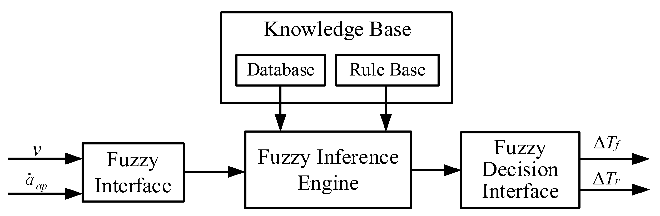
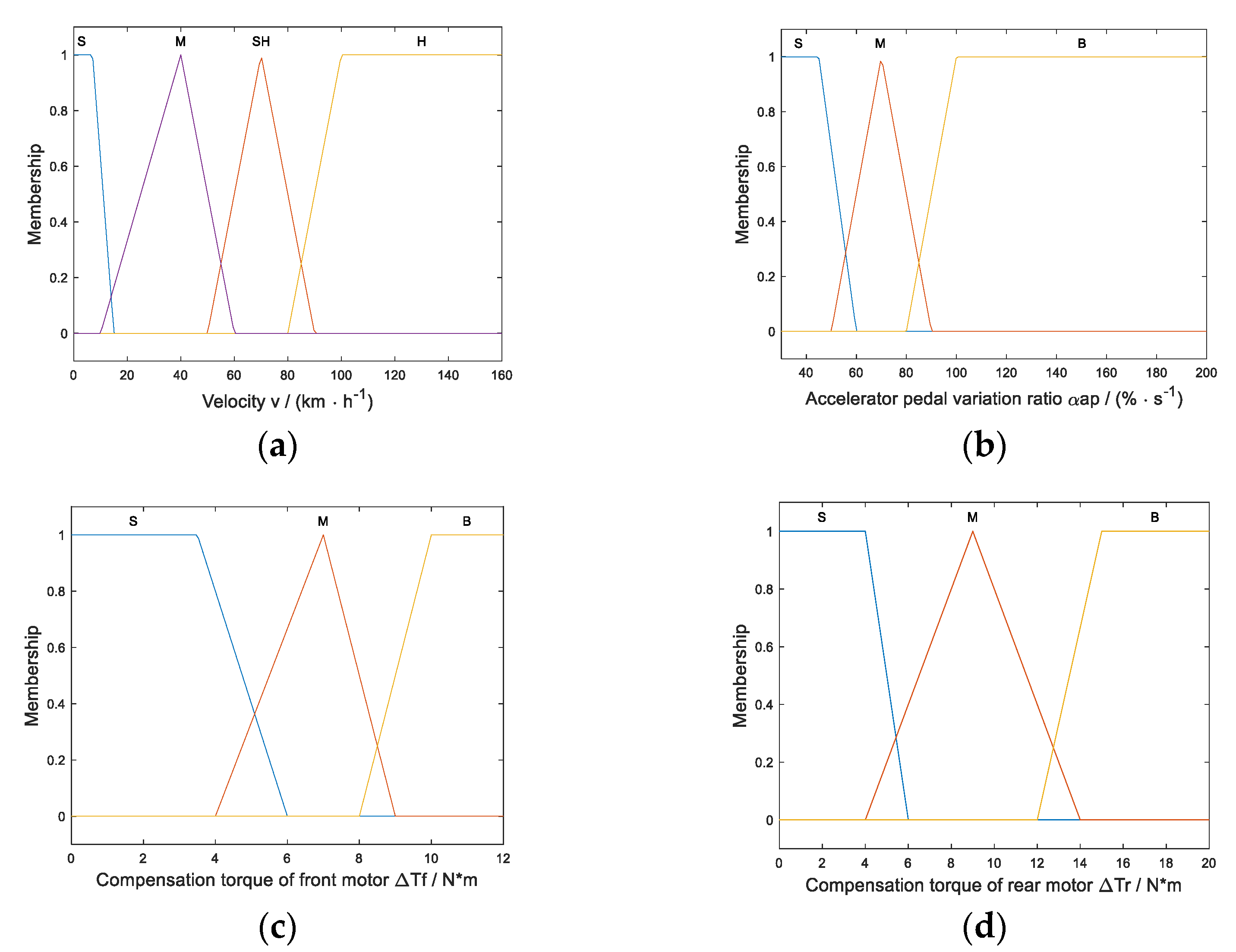
4. Torque Compensation Strategy Based on Fuzzy Control for High Power Demand Conditions

The reference torque distribution strategy based on optimal instantaneous energy consumption power is suitable for normal working conditions. However, it may cause a slow start and insufficient acceleration under high power demand conditions such as vehicle starting and rapid acceleration [23]. Therefore, according to the vehicle state and driver’s driving intention, the fuzzy control algorithm is used in this paper to formulate the torque compensation for high power demand conditions, and accordingly, to achieve outstanding dynamic performance.
In this work, data of vehicle operation and driver manipulation based on the skilled electric taxi driver during the driving process were firstly collected and analyzed; then, driving torque compensation strategy based on fuzzy control was established by combining the vehicle dynamics in vehicle starting and rapid acceleration conditions. In addition, since the sudden change in the driving torque has a considerable influence on the vehicle ride comfort, the limit of the jerk should be fully considered when determining the maximum value of the compensation torque, so it can avoid the decrease in ride comfort caused by excessive and unreasonable torque compensation. The jerk can be expressed as:
j = d 2 v d t 2 1 m ( i η T R Δ T Δ t )
where j is the jerk caused by changes in vehicle acceleration in m/s3, i is the transmission ratio, m is the vehicle mass in kg, and ηT is the drive system efficiency. It can be deduced from the formula that the greater change rate of the acceleration is, the bigger the jerk will be. Hence, Formula (12) can be transferred to:
Δ T m R i η T j Δ t
where ∆T is the compensation torque in N∙m and ∆t is the motor torque response time in s. The recommended value of jerk is j ≤ 10 m·s−3 [24]. The degree of jerk is proportional to the change rate of the motor driving torque. Therefore, the change rate of the motor torque should satisfy the requirement of driving comfort.
As shown in Figure 2, we selected the velocity and accelerator pedal opening change rate as the input variables of the fuzzy control algorithm, and the compensation torque of the front and rear motor as the output variables of the fuzzy control algorithm. According to the velocity range and driver operation data, the domain and membership of input variables and output variables can be determined. For input variables, the domain of velocity is selected as v = [0, 160], and its fuzzy subsets are equally divided into four levels: {Small, Medium, Slightly High, High}, denoted as {S, M, SH, H}. The domain of accelerator pedal opening variation rate is selected as α a p = [ 30 , 200 ] , and its fuzzy subsets are equally divided into three levels: {Small, Medium, Big}, denoted as {S, M, B}. Correspondingly, for output variables, the domain of front motor compensation torque is Δ T f = [ 0 , 12 ] , and its fuzzy subsets are equally divided into three levels: {Small, Medium, Big}, denoted as {S, M, B}. The domain of rear axle compensation torque is Δ T r = [ 0 , 20 ] , and its fuzzy subsets are divided into three levels: {Small, Medium, Big}, denoted as {S, M, B}. The membership function of input and output variables is shown in Figure 3.
After determining the membership function of input and output variables, the actual demand torque variation law of the reference vehicle under high power demand conditions is analyzed, and the fuzzy rules for torque compensation of the front and rear motors are conducted and are shown in Table 2. The different torque compensation amounts of the front and rear motors can be obtained from fuzzy rule according to the different fuzzy membership degrees corresponding to the input variables under different working conditions, thereby enhancing the vehicle dynamics for high power demand conditions.

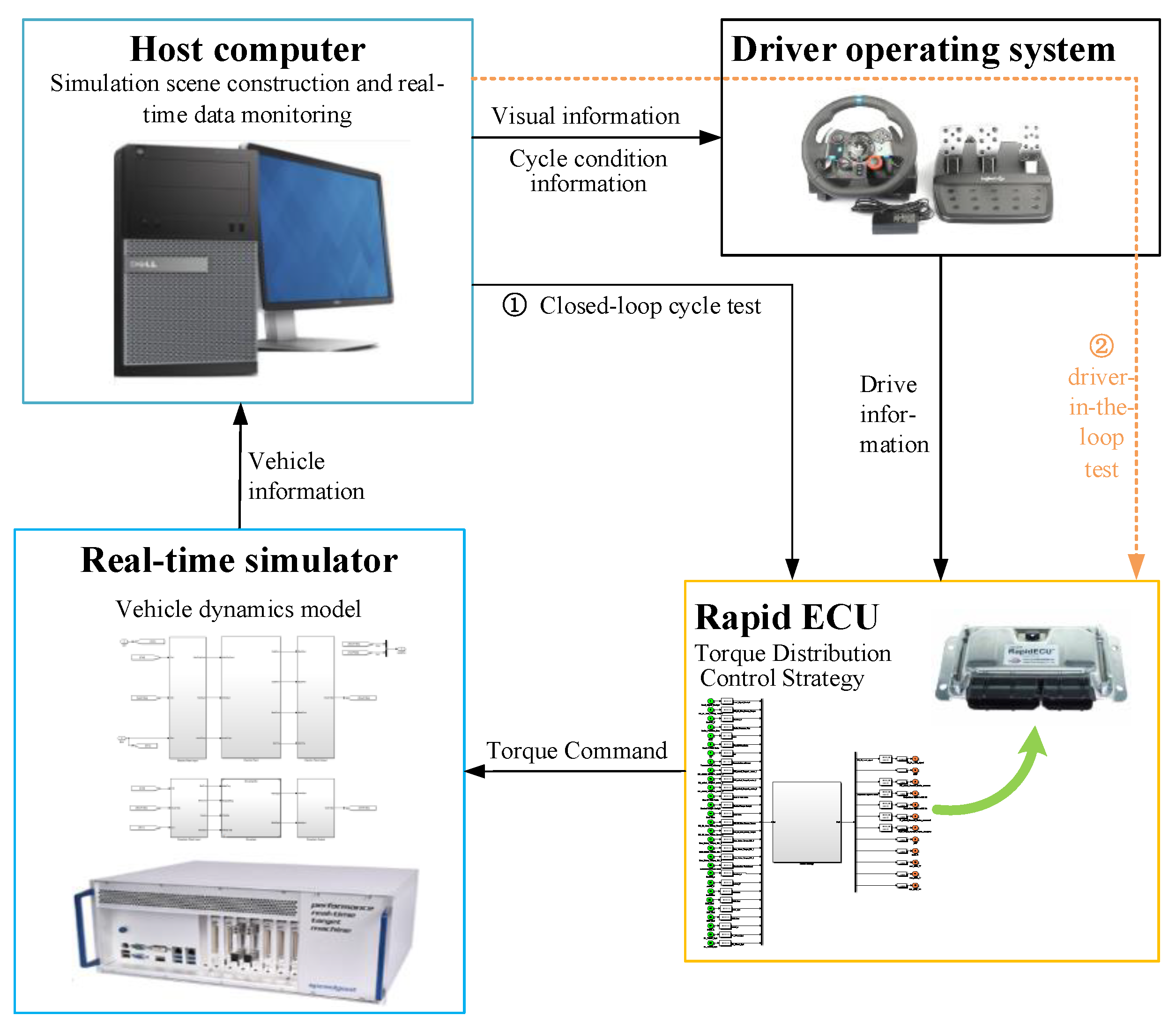
5. Hardware-in-the-Loop Simulation Results and Analysis

In order to verify the effectiveness of the drive control strategy proposed in this paper, the hardware-in-the-loop simulation system shown in Figure 4 was established. The hardware-in-the-loop simulation system is generally composed of a host computer, a real-time simulator, the RapidECU, and the driver operating system. During the development, the drive control strategy model was developed in Simulink and first tested by using the model-in-loop on the computer. Subsequently, the C code of the drive strategy is generated via rapid code-generation technology and downloaded to the controller, RapidECU. Simultaneously, the vehicle dynamics model is developed and runs in the Speedgoat real-time simulator. Then, the host computer, RapidECU, Speedgoat, and driver operating system are connected together via the data cable. The vehicle signals such as velocity, acceleration, wheel speed, and so on are transmitted to each other through the CAN bus. The system can perform both a closed-loop cycle test, as shown in path ① to test the performance of vehicle cycle conditions, and a driver-in-the-loop test, as shown in path ② to simulate actual driver operations.

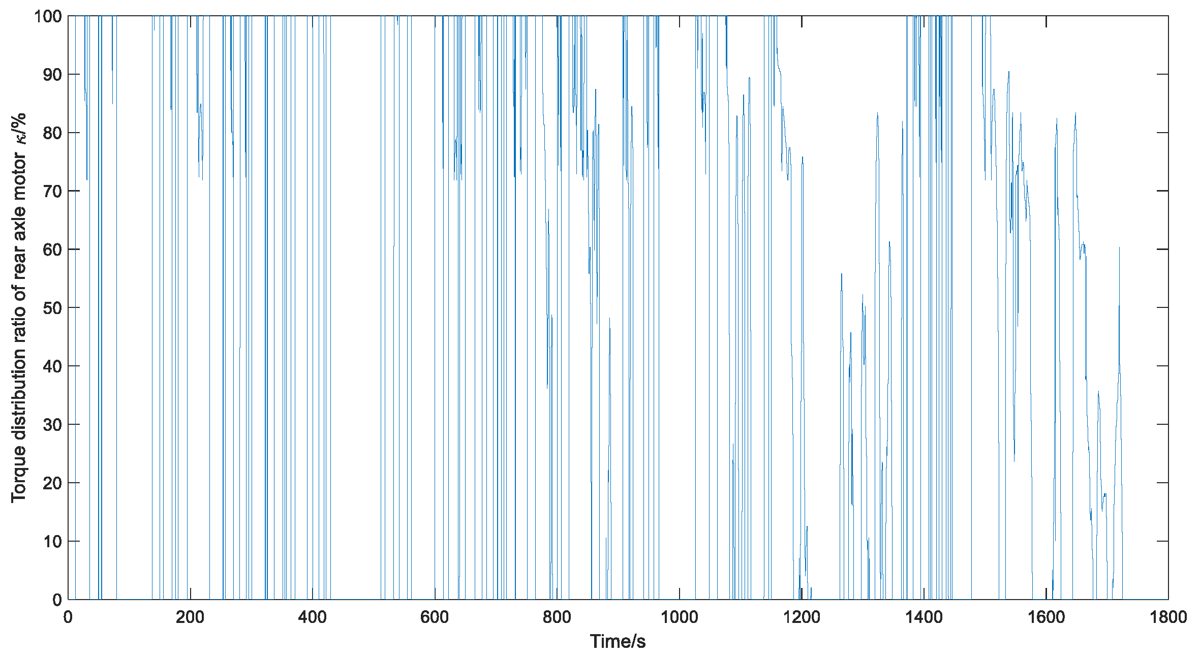
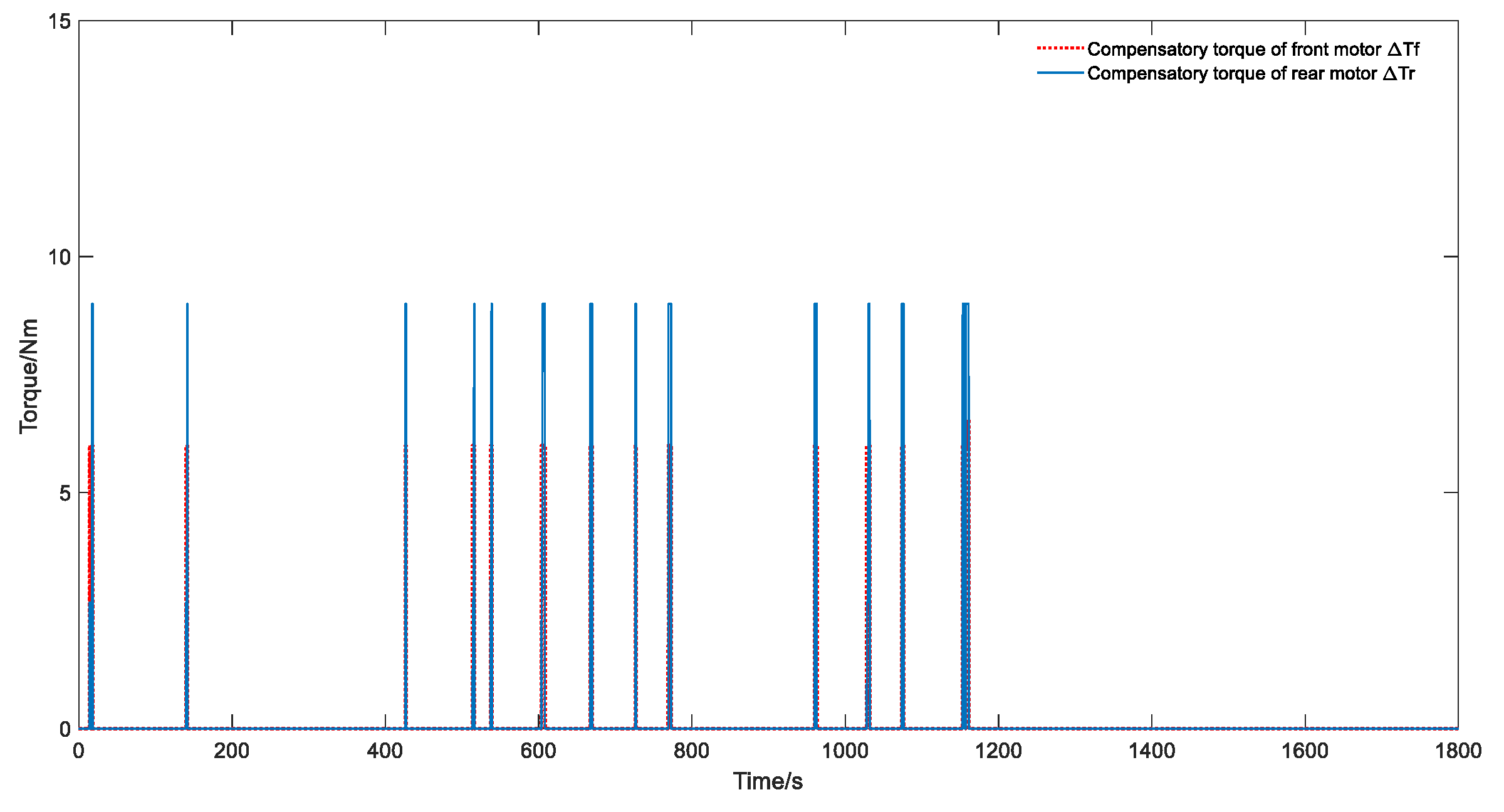
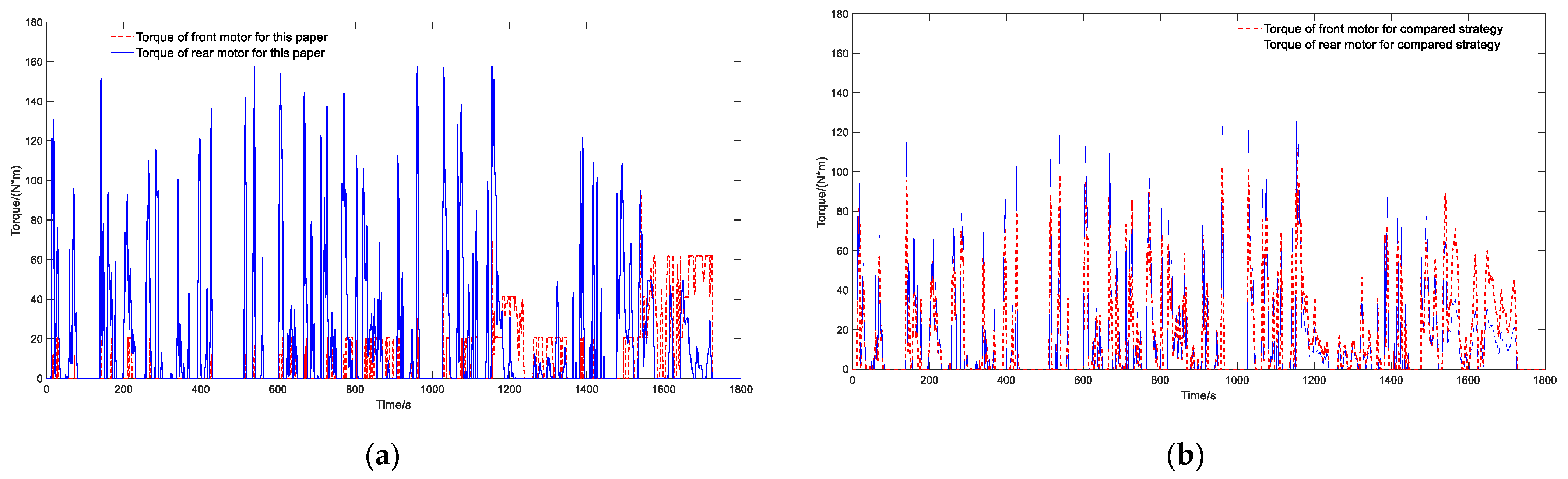
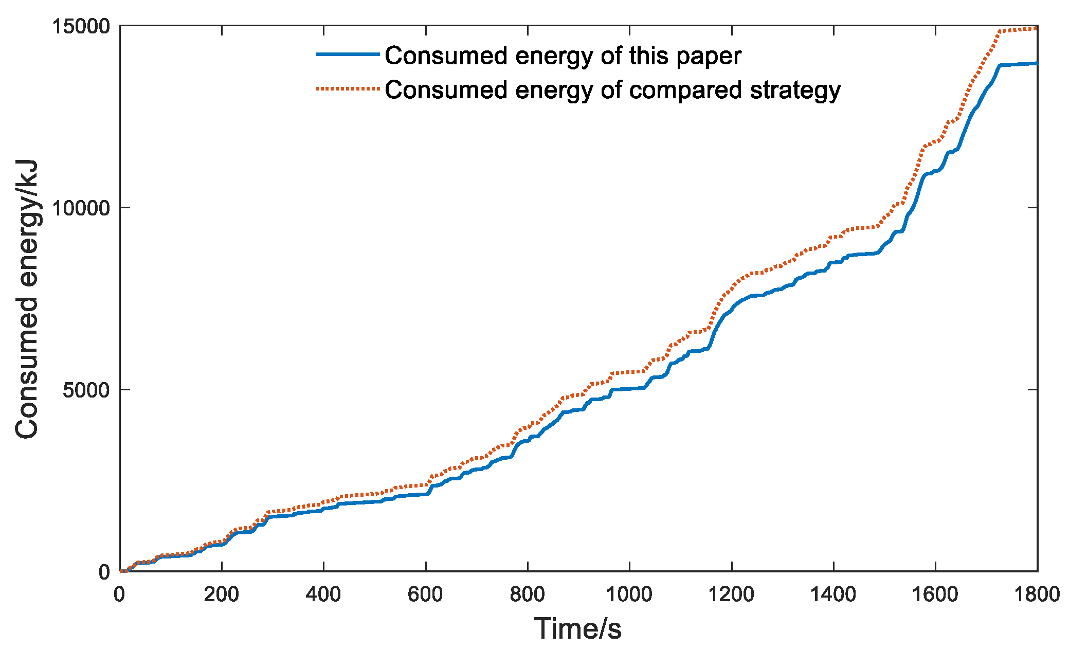
5.1. Results for WLTC

A single working condition cannot fully reflect the energy consumption state, so the vehicle economy is usually tested and verified by the cycle working condition. In order to verify the vehicle economy performance of the control strategy, the WLTC is selected as the test condition, which can represent four different working conditions: urban (low velocity), suburban (medium velocity), rural (high velocity), and highway (ultra-high velocity) [25,26]. The driving control strategy in this paper and a comparison strategy with the equal-load driving control strategy were carried out by using WLTC to verify the vehicle economy performance.
It can be seen from Figure 5 that the drive control strategy proposed in this paper can ensure that the actual velocity adequately follows the desired velocity. From Figure 6, it can be seen that when the drive control strategy of this paper is adopted, most of the torque distribution ratio κ is equal to or close to 1 at medium and low velocity; that is, all or most of the vehicle power is provided by the rear motor. That means the front motors do not participate in driving in these times, so the rear motor can improve its working efficiency since the load of the rear motor is increased. Then, from Figure 7, at the time of start-up and sudden acceleration, the compensation torque is activated, thereby reducing the start-up time and acceleration time. Moreover, compared with the motor torque in Figure 8b, most of the drive torques at the low and medium velocity of WLTC in Figure 8a are supplied by the rear motor, and the load of the rear motor increases, thereby improving its efficiency. Correspondingly, at high velocities in WLTC, the distributed torque of the front motors is greater in Figure 8a, and it takes full advantage of the front motors’ ability to maintain constant torque at high velocities, thereby ensuring the driving stability.
Compared to the working points of different strategies in Figure 9a, it can be inferred that the low-efficiency operating point of front motors at low speed and low torque is greatly reduced when adopting the control strategy proposed in this paper, and the working points in the range of 2500 r/min to 3500 r/min move towards high torque areas, which is beneficial to improve the front motor efficiency. Similarly, it can be seen from Figure 9b that, as the rear motor is commonly used at low and medium velocity, its load has been effectively increased at low and medium speeds of 0–5000 r/min, thus making more effective use of the high-efficiency motor area between the rated torque and the maximum torque. Moreover, in the range above 5000 r/min, the torque of the rear motor is lower than that of the comparison strategy, so more torque is allocated to the front motors, which are more suitable for high velocity.
Due to the improvement in the motor efficiency by using the strategy in this paper, the drive system will consume less battery energy for the same torque demand. It can be seen from Figure 10 that in WLTC, the SOC using the strategy of this paper decreases more slowly than the comparison strategy, and the final SOC is 0.52% higher than that of the comparison strategy, thereby effectively improving the driving range and battery life. Specifically, from Figure 11, it can be deduced that the energy consumption is reduced by 953 kJ compared with the comparison strategy; that is, the energy consumption is reduced by 6.45%, which represents considerable energy saving for electric vehicles. Therefore, at certain operating points of cycle conditions, the drive control strategy proposed in this paper can reasonably distribute the torque load between the front and rear axle motors and increase the number of operating points in the high-efficiency motor area; hence, the working efficiency of the motor can be effectively improved, thereby reducing the energy consumption and improving the vehicle economy.

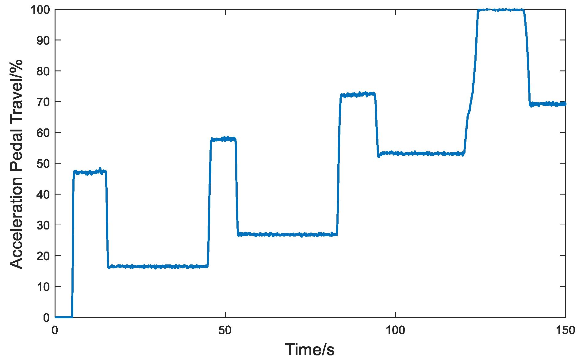
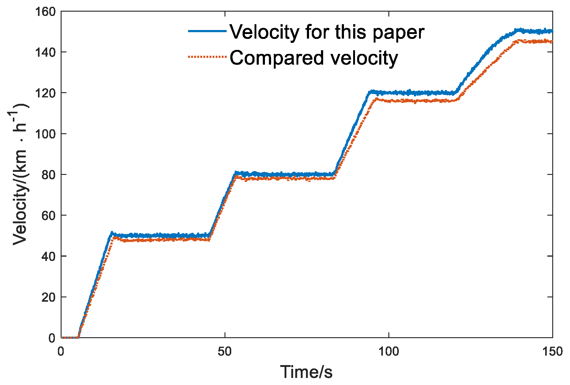
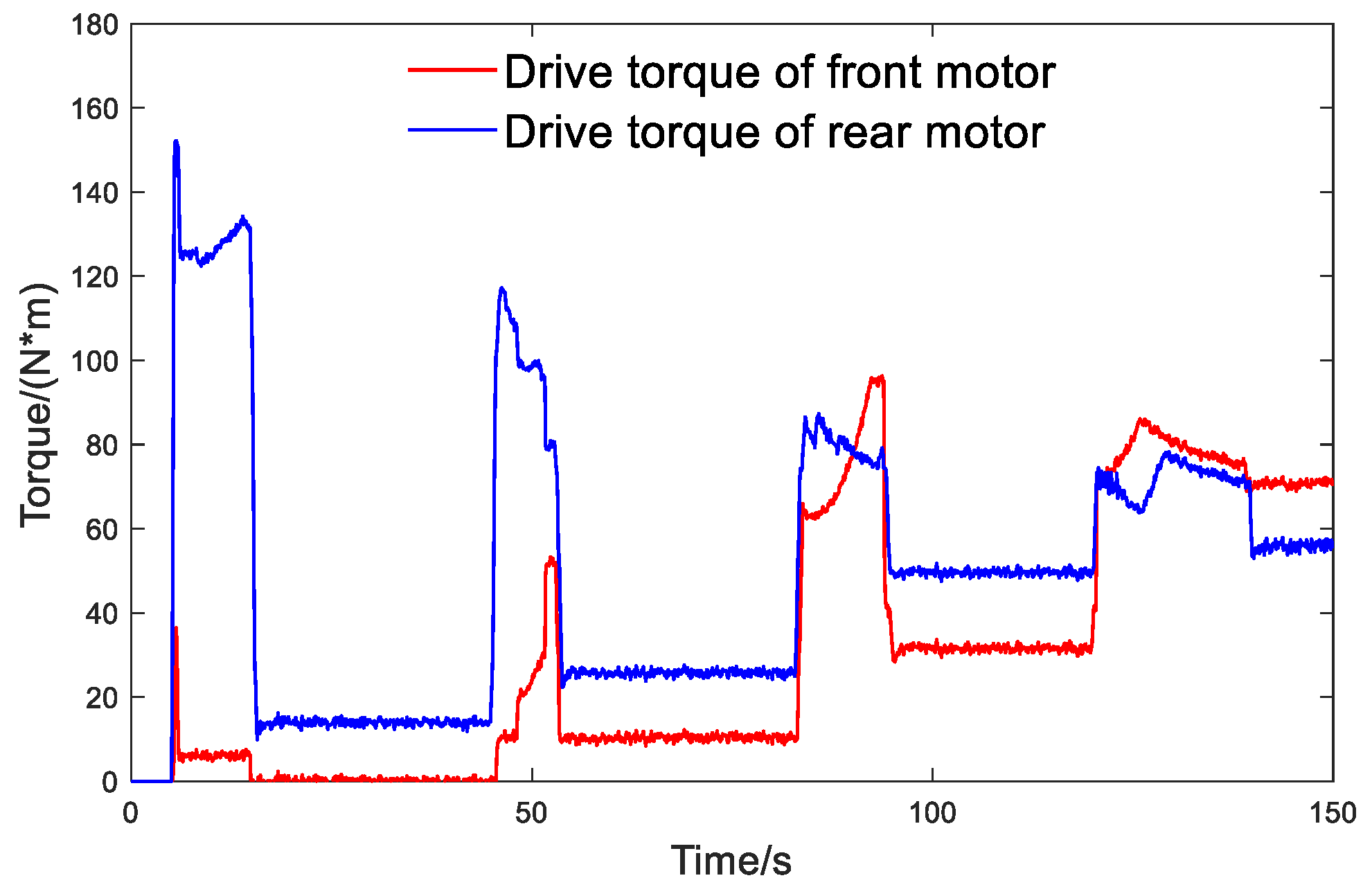
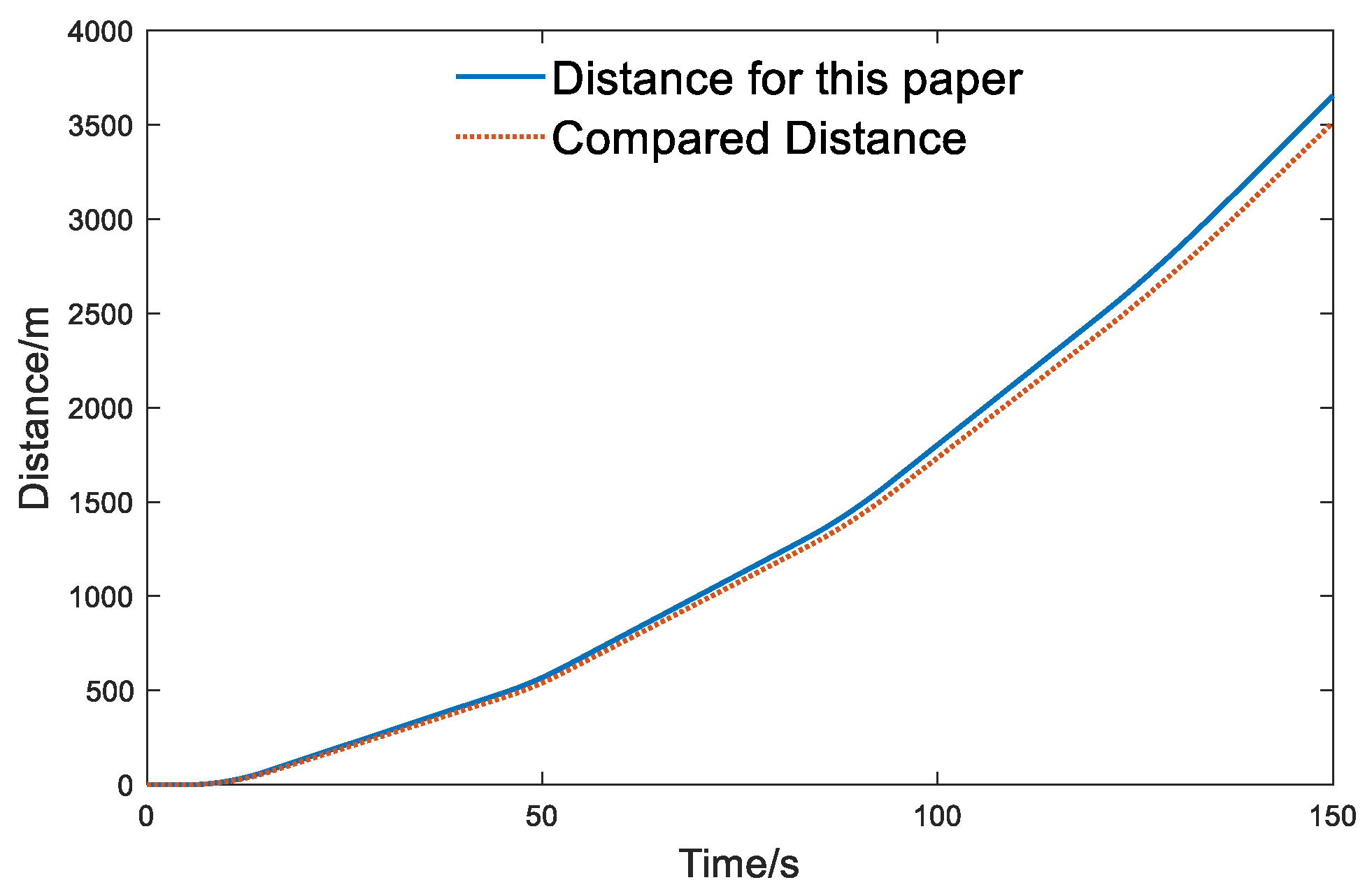
5.2. Variable Acceleration Conditions

In order to verify the vehicle dynamics performance, a driver-in-the-loop simulation was used to conduct a start-up and acceleration test, and the results of using the strategy proposed in this paper and the compared strategy without torque compensation are discussed here. As shown in Figure 12, the tester achieved the vehicle start and four accelerations by controlling the opening of the accelerator pedal, and at the same time reduced the opening of the accelerator pedal to put the vehicle into a cruising state after each acceleration to a specific velocity. This maneuver can reflect the acceleration and dynamics performance of the vehicle from a standstill to a relatively high velocity. Combining Figure 13 and Figure 14, it can be seen that due to the effect of compensation torque, in the acceleration times of 5–15 s, 87–94 s, and 132–135 s, the velocity of the strategy in this paper increases faster than that of the compared strategy; however, while in an acceleration time of 45–54 s without compensation torque, the acceleration trend of the two strategies is nearly the same. Therefore, the torque compensation strategy adopted in this paper can effectively improve the acceleration performance of the vehicle.
Combining Figure 15 and Figure 16, it can be seen that at the moment of 5–15 s, the vehicle starts and accelerates rapidly at low velocity and the required torque is relatively large, so all the front and rear axle motors provide compensation torque for starting up to ensure that the vehicle can quickly start and accelerate. Similarly, at 87–94 s and 132–135 s, the demand power is large, so the torque compensation module is triggered, and motors on both the front and rear axle obtained the torque compensation. However, different from the acceleration stage, the torque required by the vehicle in the cruise stage is small and does not require torque compensation; even at 15–45 s in the cruising stage, only the rear axle motor can meet the torque demand from Figure 15. In addition, it can be seen from Figure 16 that during the high-velocity acceleration, the rear motor is already in the constant power range, and its torque decreases as the vehicle speed increases, so more torque is distributed to the front motor, resulting in the higher efficiency of the multi-motor-drive system, thereby ensuring the vehicle dynamics and stability performance at high-velocity driving. At last, by comparing the driving distance in Figure 17, it can be seen that the vehicle can travel an additional 146 m by using the control strategy in this paper; that is, it can travel a longer distance under the same accelerator manipulation action, so a better acceleration performance is achieved.
Therefore, the drive control strategy proposed in this paper can reasonably control the workload of the front and rear motors at different velocities and accelerations, and realize the torque compensation under high power demand conditions such as starting and rapid acceleration, thus effectively improving the vehicle dynamic performance.

6. Conclusions

Four-wheel-drive electric vehicles with multiple motors have the advantages of energy saving, environmental protection, and excellent dynamics performance, and have gradually become an important development trend in electric vehicles in recent years. For the four-wheel-drive electric vehicle with dual motors on the front axle and a single motor on the rear axle studied in this paper, the single motor on the rear axle is usually used for low- or medium-velocity conditions such as urban driving, and the dual motors on the front axle are usually used for high-velocity conditions and high power demand conditions. Given the drive configuration characteristics of the studied vehicle, we designed a multi-mode optimal drive control strategy based on hierarchical control. In terms of the vehicle economy module, we proposed a reference torque of the front and rear axle motors based on the optimal instantaneous energy consumption power to improve the energy consumption efficiency. As for the vehicle dynamics module, we developed a torque compensation strategy based on fuzzy control to improve the vehicle dynamics under high power demand conditions such as starting up or rapid acceleration. Ultimately, through the hardware-in-the-loop simulation system, the closed-loop cycle test was carried out in WLTC, and the results show that the energy consumption of the proposed strategy is reduced by 6.45% compared to the compared strategy. The driver-in-the-loop test results show that the proposed driving optimization control strategy can realize torque compensation under high power demand conditions, and effectively improve the vehicle dynamics. However, we did not investigate vehicle steering based on the advantages of dual motors on the front axle, so research on the lateral dynamics of four-wheel-drive electric vehicles with multiple motors will be carried out in the next stage.

Author Contributions

Conceptualization, S.X.; methodology, S.X. and L.W.; software, S.X.; validation, S.X., X.Z. and Z.B.; formal analysis, S.X.; investigation, S.X., L.W. and X.Z.; resources, X.Z.; data curation, S.X.; writing—original draft preparation, S.X. and L.W.; writing—review and editing, S.X. and L.W.; visualization, Y.J.; supervision, S.X.; project administration, S.X.; funding acquisition, S.X. and Z.B. All authors have read and agreed to the published version of the manuscript.

Funding

This work was funded by the National Natural Science Foundation of China (grant number 52002309), the Key Research & Development Project of Shaanxi Province (grant number 2019ZDLGY15-02), the Natural Science Foundation Project of Shaanxi Province (grant numbers 2020JQ-669 and 2021JM-363), and the Open Fund Project of Key Laboratory for Automotive Transportation Safety Enhancement Technology of the Ministry of Communication, PRC (grant number 300102229509).

Institutional Review Board Statement

Not applicable.

Informed Consent Statement

Not applicable.

Data Availability Statement

The data presented in this study are available on request from the corresponding author.

Conflicts of Interest

The authors declare no conflict of interest.

References

  1. Van Mierlo, J.; Berecibar, M.; El Baghdadi, M.; De Cauwer, C.; Messagie, M.; Coosemans, T.; Hegazy, O. Beyond the State of the Art of Electric Vehicles: A Fact-Based Paper of the Current and Prospective Electric Vehicle Technologies. World Electr. Veh. J. 2021, 12, 20. [Google Scholar] [CrossRef]
  2. Liu, H.; Chen, X.; Wang, X. Overview and prospects on distributed drive electric vehicles and its energy saving strategy. Prz. Elektrotechniczny 2012, 88, 122–125. [Google Scholar]
  3. Li, Z.; Khajepour, A.; Song, J. A comprehensive review of the key technologies for pure electric vehicles. Energy 2019, 182, 824–839. [Google Scholar] [CrossRef]
  4. Puma-Benavides, D.S.; Izquierdo-Reyes, J.; Calderon-Najera, J.D.D.; Ramirez-Mendoza, R.A. A systematic review of technologies, control methods, and optimization for extended-range electric vehicles. Appl. Sci. 2021, 11, 7095. [Google Scholar] [CrossRef]
  5. Tobolar, J.; de Castro, R.; Bleck, U.; Satzger, C.; Brembeck, J.; Hirano, Y. Comparative evaluation of energy efficiency of electrical vehicle powertrain configurations. In The Dynamics of Vehicles on Roads and Tracks, 1st ed.; CRC Press: Graz, Austria, 2016; pp. 691–699. [Google Scholar]
  6. Kumar, M.S.; Revankar, S.T. Development scheme and key technology of an electric vehicle: An overview. Renew. Sustain. Energy Rev. 2016, 70, 1266–1285. [Google Scholar] [CrossRef]
  7. Chatzikomis, C.; Zanchetta, M.; Gruber, P.; Sorniotti, A.; Modic, B.; Motaln, T.; Gotovac, G. An energy-efficient torque-vectoring algorithm for electric vehicles with multiple motors. Mech. Syst. Signal Process. 2019, 128, 655–673. [Google Scholar] [CrossRef]
  8. Raslavičius, L.; Keršys, A.; Makaras, R. Management of hybrid powertrain dynamics and energy consumption for 2WD, 4WD, and HMMWV vehicles. Renew. Sustain. Energy Rev. 2017, 68, 380–396. [Google Scholar] [CrossRef]
  9. Li, Y.; Zhang, J.; Guo, K.; Wu, D. Optimized Torque Distribution Algorithm to Improve the Energy Efficiency of 4WD Electric Vehicle 2014-01-2374; SAE International: Pittsburgh, PA, USA, 2014. [Google Scholar]
  10. Yuan, X.; Wang, J. Torque Distribution Strategy for a Front- and Rear-Wheel-Driven Electric Vehicle. IEEE Trans. Veh. Technol. 2012, 61, 3365–3374. [Google Scholar] [CrossRef]
  11. Pennycott, A.L.; Novellis, D.; Gruber, P.; Sorniotti, A.; Goggia, T. Enhancing the Energy Efficiency of Fully Electric Vehicles via the Minimization of Motor Power Losses. In Proceedings of the 2013 IEEE International Conference on Systems, Man, and Cybernetics, Manchester, UK, 13–16 October 2013. [Google Scholar]
  12. Yang, Y.P.; Shih, Y.C.; Chen, J.M. Real-time torque-distribution strategy for a pure electric vehicle with multiple traction motors by particle swarm optimization. IET Electr. Syst. Transp. 2016, 6, 76–87. [Google Scholar] [CrossRef]
  13. Chen, Y.; Wang, J. Fast and Global Optimal Energy-Efficient Control Allocation with Applications to Over-Actuated Electric Ground Vehicles. IEEE Trans. Control Syst. Technol. 2012, 20, 1202–1211. [Google Scholar] [CrossRef]
  14. Yu, Z.; Zhang, L.; Xiong, L. Optimized torque distribution control to achieve higher fuel economy of 4WD electric vehicle with four in-wheel motors. J. Tong Ji Univ. 2005, 33, 1355–1361. [Google Scholar]
  15. Xu, S.; Zhao, X.; Yang, N.; Bai, Z. Control Strategy of Braking Energy Recovery for Range-Extended Electric Commercial Vehicles by Considering Braking Intention Recognition and Electropneumatic Braking Compensation. Energy Technol. 2020, 8, 2000407. [Google Scholar] [CrossRef]
  16. Qin, D.; Zhou, M.; Hu, M.; Hu, J.; Chen, S. Strategy of Acceleration Torque Compensation Control for Electric Vehicle. J. Highw. Transp. Res. Dev. 2012, 29, 146–151. [Google Scholar]
  17. Wang, J.; Yang, J.; Cai, Z.; Zhang, X. The Optimum Control Strategy of Battery Electric Car Based on Fuzzy Control. Automot. Eng. 2009, 31, 362–365. [Google Scholar]
  18. Tseng, Y.H.; Yang, Y.P. Torque and Battery Distribution Strategy for Saving Energy of an Electric Vehicle with Three Traction Motors. Appl. Sci. 2020, 10, 2653. [Google Scholar] [CrossRef] [Green Version]
  19. De Filippis, G.; Lenzo, B.; Sorniotti, A.; Sannen, K.; De Smet, J.; Gruber, P. On the energy efficiency of electric vehicles with multiple motors. In Proceedings of the 2016 IEEE Vehicle Power and Propulsion Conference (VPPC), Hangzhou, China, 17–20 October 2016. [Google Scholar]
  20. Song, Z.; Hofmann, H.; Li, J.; Wang, Y.; Lu, D.; Ouyang, M.; Du, J. Torque Distribution Strategy for Multi-PMSM Applications and Optimal Acceleration Control for Four-Wheel-Drive Electric Vehicles. J. Dyn. Syst. Meas. Control 2020, 142, 021001. [Google Scholar] [CrossRef]
  21. De Pinto, S.; Camocardi, P.; Sorniotti, A.; Gruber, P.; Perlo, P.; Viotto, F. Torque-fill control and energy management for a four-wheel-drive electric vehicle layout with two-speed transmissions. IEEE Trans. Ind. Appl. 2016, 53, 447–458. [Google Scholar] [CrossRef]
  22. Zhang, S.; Xiong, R.; Zhang, C.; Sun, F. An optimal structure selection and parameter design approach for a dual-motor-driven system used in an electric bus. Energy 2016, 96, 437–448. [Google Scholar] [CrossRef]
  23. Hu, J.; Zu, G.; Jia, M.; Niu, X. Parameter matching and optimal energy management for a novel dual-motor multi-modes powertrain system. Mech. Syst. Signal Process. 2019, 116, 113–128. [Google Scholar] [CrossRef]
  24. Chen, S.J.; Qin, D.T.; Hu, M.H.; Wei, H.B. Ramp adaptive launch control strategy of pure electric vehicles. J. Chongqing Univ. 2012, 35, 1–7. [Google Scholar]
  25. Tutuianu, M.; Bonnel, P.; Ciuffo, B.; Haniu, T.; Ichikawa, N.; Marotta, A.; Steven, H. Development of the World-wide harmonized Light duty Test Cycle (WLTC) and a possible pathway for its introduction in the European legislation. Transp. Res. Part D Transp. Environ. 2015, 40, 61–75. [Google Scholar] [CrossRef]
  26. Jiao, Z.; Ma, J.; Zhao, X.; Zhang, K.; Meng, D.; Li, X. Development of a Rapid Inspection Driving Cycle for Battery Electric Vehicles Based on Operational Safety. Sustainability 2022, 14, 5079. [Google Scholar] [CrossRef]
Figure 1. The architecture of torque optimization distribution strategy.
Sustainability 14 07378 g001
Figure 2. Architecture of driver’s driving intention recognition system based on fuzzy algorithm.
Sustainability 14 07378 g002
Figure 3. The input and output membership functions of the torque compensation controller: (a) velocity; (b) accelerator pedal opening variation rate; (c) compensation torque of front motor; (d) compensation torque of rear motor.
Sustainability 14 07378 g003
Figure 4. Hardware-in-the-loop simulation system.
Sustainability 14 07378 g004
Figure 5. Velocity in WLTC.
Sustainability 14 07378 g005
Figure 6. Drive torque distribution ratio of the rear motor in WLTC.
Sustainability 14 07378 g006
Figure 7. Compensation torque in WLTC.
Sustainability 14 07378 g007
Figure 8. Motor torque distribution in WLTC: (a) motor torque of the control strategy proposed in this paper; (b) motor torque of the comparison strategy.
Sustainability 14 07378 g008
Figure 9. Comparison of working points of motors in WLTC: (a) working point of the front motor; (b) working point of the rear motor.
Sustainability 14 07378 g009
Figure 10. SOC changes in WLTC.
Sustainability 14 07378 g010
Figure 11. Energy consumption in WLTC.
Sustainability 14 07378 g011
Figure 12. Accelerator pedal opening variation.
Sustainability 14 07378 g012
Figure 13. Velocity in variable acceleration conditions.
Sustainability 14 07378 g013
Figure 14. Torque compensation in variable acceleration conditions.
Sustainability 14 07378 g014
Figure 15. Torque distribution ratio of rear motor in variable acceleration conditions.
Sustainability 14 07378 g015
Figure 16. Torque of front and rear motors in variable acceleration conditions.
Sustainability 14 07378 g016
Figure 17. Driving distance in variable acceleration conditions.
Sustainability 14 07378 g017
Table 1. Vehicle parameters and performance index.
ParameterValueUnit
Vehicle parametersCurb weight m01520kg
Max. weight M1895kg
wind resistance coefficient Cd0.29-
Windward area A2.27m2
Tire radius R0.307m
Rolling resistance coefficient f0.0165-
Rotational mass conversion factor δ1.0425-
Wheelbase L2700mm
Front motorRated speed3000r∙min−1
Rated torque57N∙m
Peak power30kW
Peak speed7000r∙min−1
Rear motorRated speed2500r∙min−1
Rated torque120N∙m
Peak power60kW
Peak speed9500r∙min−1
Table 2. Fuzzy rules of the torque compensation module. (a) Fuzzy rules of torque compensation for front motors. (b) Fuzzy rules of torque compensation for rear motor.
(a)
VelocityAccelerator Pedal Opening Variation Rate
SMB
S---
M--S
SHMBB
HBBB
(b)
VelocityAccelerator Pedal Opening Variation Rate
SMB
SSMB
MMBB
SH--M
HSSM
Publisher’s Note: MDPI stays neutral with regard to jurisdictional claims in published maps and institutional affiliations.

