Article

Experimental Investigation on Waste Heat Recovery from a Cement Factory to Enhance Thermoelectric Generation

1
Mechanical Engineering Department, Faculty of Engineering, Al-Hussein Bin Talal University, Ma’an 71111, Jordan
2
Mechanical Engineering Department, Benha Faculty of Engineering, Benha University, Benha 13518, Egypt
3
Mechanical Engineering Department, Faculty of Engineering, Mutah University, Al-Karak 61710, Jordan
4
Environmental Engineering Department, Faculty of Engineering, Al-Hussein Bin Talal University, Ma’an 71111, Jordan
5
Department of Electrical Engineering, College of Engineering in Wadi Alddawasir, Prince Sattam bin Abdulaziz University, Wadi Alddawasir 11991, Saudi Arabia
6
Lafarge Jordan Cement, Rashadiya 25111, Jordan
*
Author to whom correspondence should be addressed.
Sustainability 2022, 14(16), 10146; https://doi.org/10.3390/su141610146
Submission received: 26 May 2022 / Revised: 11 August 2022 / Accepted: 11 August 2022 / Published: 16 August 2022

Abstract

:
This work investigated the potential for waste heat recovery from a cement factory using thermoelectric generation (TEG) technology. Several TEGs were placed on a secondary coaxial shell separated from the kiln shell by an air gap. The performance of the system was tested and evaluated experimentally. Two cooling methods, active water and forced air, were considered. A forced closed-loop water cooling system with a heat exchanger was considered for the active-water cooling method. A heat exchanger was inserted before the water tank to improve cooling efficiency by reducing the inlet temperature of the cooling water tank, in contrast to forced-air cooling, in which a heatsink was used. The obtained results indicated that the closed-loop water-cooled system equipped with a radiator, i.e., active water, has the highest conversion efficiency. The maximum absorbed heat for the forced-air and active-water cooling systems were 265.03 and 262.95 W, respectively. The active-water cooling method improves the power of TEG by 4.4% in comparison with forced-air cooling, while the payback periods for the proposed active-water and forced-air cooling systems are approximately 16 and 9 months, respectively.

1. Introduction

Global warming and resource scarcity are still the main issues addressed today in both economic and scientific conferences and meetings [1,2,3]. Waste heat refers to the heat generated in a system as a byproduct or that leaves the system without adding valuable work [4,5]. Moreover, when this surplus heat goes into the system and mixes with the surrounding atmosphere or groundwater, it becomes unreachable and hard to recover [6]. In this regard, the waste heat recovery system needs to be appropriately evaluated and designed. Moreover, several factors play a crucial role in the selection and efficiency of waste heat recovery systems, for example, the quality and quantity of such waste heat. In fact, the cement production process uses 3 to 4 GJ of energy per ton of cement, and around 40% of the energy is wasted [7]. This makes cement production a perfect target for waste heat recover, not only to minimize and save production costs, but also to save the world and atmosphere from the enormous amount of CO2 generated by the cement sector.
TEG converts heat directly to electricity. It mainly consists of a thermocouple element (n-type and p-type) covered with an aluminum oxide plate. These thermocouples are electrically in series to increase the generated voltage and thermally in parallel to reduce thermal resistance. The main advantage of these technologies is that there are no moving parts, so there is almost no need for maintenance; hence, this technology can be compatible for use in remote and hostile environments such as space applications and missions [8,9]. Thermoelectric devices are most simply classified based upon the heat-flow direction. For instance, if the thermoelectric device absorbs heat and generates a voltage, it will be classified as TEG, but if a thermoelectric device converts electrical energy to a temperature gradient, it will be considered as a TEC (thermoelectric cooler) [10,11].
TEG application varies, from large scale in industries to small scale. Recently, TEG has been applied towards energy recovery from the human body [12,13,14]. For instance, on the small scale, Lu et al. [14] fabricated a flexible TEG of Bi2Te3 and Sb2Te3 deposited on the surface of silk fabric. Such fabric effectively generates electricity from the human body with high durability, surviving over 100 instances of bending and twisting. TEG is extensively used in the transportation sector to recover energy from exhaust gases [15,16,17]. Demir and Dincer [17] proposed a novel TEG design that uses the temperature difference between the exhaust gas and the inlet air from the front grid to generate electricity that reached 158 W. Mahmoudinezhad et al. [18] studied the effect of solar radiation on the power output of a hybrid system composed of TEG and concentrated photovoltaics (CPV). The authors found that the fluctuations of solar radiation have a significant effect on the temperature of the different components of the system and thus on the power output. Rezk et al. [19] also studied the MPPT optimization of a hybrid PV/thermoelectric system under different conditions for harvesting and recovering solar radiation energy. A hybrid TEG and parabolic solar collector demonstrated high energy and exergy efficiencies [20].
On the industrial scale of waste heat at temperatures of up to 350 °C, Meng et al. [21] proposed an energy recovery system of TEG using finite-time thermodynamics. A maximum power of 1.45 kW/m2 could be recovered with an efficiency of 4.5% at 350 °C and a 4-year payback period. Li et al. [22] theoretically and experimentally studied the application of TEG to a micro-channel heat pipe for waste heat recovery. The heat pipe is an effective method for converting low heat flux into high heat flux. TEG can be used instead of the condenser in the organic Rankine cycle operated by a solar gradient bond [23].
In the cement industry, many studies have been carried out to utilize the exhaust gases for preheaters and coolers for reuse in preprocessing and electrical generation. However, the heat loss from the kiln shell needs more investigation and study. Recently, Cheng-Ting Hsu et al. [24] studied a cement rotary kiln with a 4.8 m diameter and 76 m length. In their work, they showed that a huge heat flux of 3500 to 4000 W/m2 is dissipated in the form of radiation and convective heat from the kiln shell to the surrounding environment as a loss. This lost heat will result in huge energy loss and a CO2 footprint. Their experiment used 12 thermoelectric generators installed in a 2 m2 area. Their system was cooled with a water block attached to the cooled side of the thermoelectric system. The output power that could be generated from this system was 214 W, but they noticed that the maximum conversion efficiency is around 4.3% at 210 °C temperature difference. Lastly, they utilized the generated voltage to light up 15 LED lamps with 10 W rated power. Luo et al. [25] discussed using heat loss from the kiln shell, representing 10–15% of the energy needed to produce clinker. Specifically, their discussion focused on generating electricity for rotary kiln shells where the kiln dimensions are 4.8 m in diameter and 72 m in length. Practically, they used TEGs as waste heat recovery devices, and they succeeded in generating 211 kW of electrical power. They arranged the TEGs longitudinally on the external coaxial kiln shell to avoid adding extra load on the kiln drive, and they proved in their work that the TEGs could recover 32.85% of the lost kiln shell heat. Another important outcome of their work was that two significant parameters directly affect the system performance. The first one is the uneven thermal distribution on kiln shells, and the second is the wind speed. As the kiln is outdoor equipment, it is directly affected by the surrounding environment: for instance, wind speed. Therefore, wind speed increases the convective heat loss from the kiln shell, leading to an increase in input to the recovery system. Additionally, wind speed enhances heat removal from a forced-air cooling system, resulting in additional temperature differences across TEG.
The performance of TEG is directly dependent on two main criteria; the first one is the properties of the thermoelectric material, such as the Seebeck coefficient, electrical resistance, and thermal conductivity. In contrast, the second criterion is thermal management effectiveness for heat removal from the cold side. Thus, a mechanism for heat dissipation should be employed to maximize the overall performance and power generation [26].
Wei-Ning [27] studied different methods to assess and implicate the heat loss through the kiln shell and its influencing factors. This study uses different measuring devices and calculations to estimate the kiln heat loss for 19 days of monitoring. The calculation results show that the heat losses by convection and radiation reached 140 GJ daily, accounting for 46% and 54% of the gross heat loss, respectively. These values of energy losses correspond to an economic loss of 585 USD/day that must be recovered.
The energy loss in cement clinker production is approximately 10% to 15% of the energy consumed through the shell of the rotary kiln to the atmosphere [28].
Mirhosseini et al. [28] numerically studied the temperature distribution of arc-shaped absorbers of thermoelectric generators of a waste heat recovery system around the rotary kiln. Different TEG parameters (leg length and fill factor) and heat think thermal resistance are considered. In addition, the atmosphere air velocity and temperature are considered to reach optimal power. The results presented that higher system performance and power are obtained with the pin-fins staggered arrangement compared to the in-line arrangement. Thus, the average power generated and the average cost per power by the whole ten sections of the TEG system were obtained at 86.78, 99.19, 105.91 W/m2, and 17.56, 17.40, 20.32 USD/W, respectively, for 0.05, 0.1, and 0.2 fill factor, respectively.
The mathematical model of Bi2Te3 and Zn4Sb3 thermoelectric waste heat recovery system of an annular absorber around cement rotary kiln was developed by Mirhosseini et al. [29]. The results showed that the generated electric power for Bi2Te3 and Zn4Sb3 thermoelectric units was 119 W/m2 and 250 W//m2 under fill factors 0.05 and 0.1, respectively. Moreover, the payback period of the Bi2Te3 and Zn4Sb3 TEG systems was obtained at 8.3 and 3.58 years, respectively.
Fan and Gao [30] investigated the performance of a segmented thermoelectric power generation and reliability under steady-state conditions and transient conditions in a sinusoidal heat source operation. The findings indicate that the shorter the heat source time and amplitude, the greater the overall output of the segmented annular TEG. Additionally, when the structural parameter increases, the power output of the segmented annular TEG initially increases and then decreases. The max von Mises stresses in the hot and cold segments will always hit an optimum value when the hot end temperature is more significant than 300. In addition, the electrical output power can improve by 18.3% in comparison to the single-Skutterudite annular TEG, and the hot-segment stress is reduced by 12.5%.
A number of studies and experiments have been conducted to enhance and improve the hot-side heat collection to optimize TEG energy production, but cold-side heat treatment has a lower appeal, while the TEG conversion efficiency is expressed by the difference in temperature between the hot and cold sides. In this study, waste heat recovery will be examined using a thermoelectric generator, which is a promising technology. Centered on what has already been discussed earlier, in this study, two cooling methods were proposed: active-water cooling and forced-air (pin fin and fan) cooling methods. Cement manufacturing is one of the most intensive energy uses. Therefore, it is essential to locate methods to enhance energy use, energy efficiency, and recycle waste energy as it is important to reduce or save production costs. The goal of the current paper is to examine the manufacturing procedure of cement production to assess the practicality of employing TEG as a technology to recover the waste heat from the shell of a rotary cement kiln. Additionally, we will compare the experimental outcomes with the commercial datasheet. Thus, this study will examine TEG as a waste heat recovery system in the kiln shell and it will test the performance of the TEG units under different cooling method conditions.

2. Experiment Setup

2.1. Location

The cement plant considered in this investigation is one of the largest plants in Jordan. This factory is located in the southern part of Jordan at an altitude of about 1650 m above sea level. It has two production lines with 3200 tons/day/line capacity. The production technology in this plant is a dry process that uses a multi-stage suspension preheater equipped with a pre-calciner. A rotary kiln is considered the heart of the cement production process. It is a cylindrical rotating vessel lined inside with refractory bricks and supported by a carrying mechanism through the riding ring, as shown in Figure 1A. Its diameter is 4.5 m, it is 70 m in length, and has a speed ranging from 0.4 to 3.75 RPM. The kiln is slanted so that the discharge is lower than a horizontal plane, so that the product which is burned inside the kiln is moved to the discharge end by the kiln’s rotating movement given by the drive unit.
In general, the inner side of the kiln is covered with low thermal conductivity bricks to keep the heat inside the kiln as much as possible and to protect the outer surface of the kiln from plastic deformation. Figure 1B shows the bricks linked in the kiln and Figure 1C shows the burner that is considered the source of heat input to the kiln. The burner’s temperature ranges from 1500 °C to 1800 °C [31]. Therefore, the brick refractory has low thermal conductivity. Some of the input heat from the burner is lost and dissipated into the surrounding environment. Thus, the cement plant carefully monitors the outer kiln surface, and many technologies have been used for this purpose in this plant. For instance, a unique technique thermal scanning system for kiln shells was installed to monitor the shell surface thermal distribution. Figure 2 illustrates the thermal distribution for the outer kiln surface, which is a very helpful tool for avoiding a catastrophic incident in the kiln.
As shown in Figure 2, the thermal display profile for the complete kiln shell is under investigation, measured by a unique thermal scanning tool. This graph indicates that the most significant heat flux density and temperature value occurs between positions 30 m and 34 m, and the average temperature is around 375 °C and above. The energy flux intensity losses for the position 30 m to 34 m range from 10 kW/m² to 12.5 kW/m². Additionally, this amount of waste heat can be classified as medium-quality waste heat.
The total heat losses (radiation and convection) can be calculated from Equation (1) [32].
Q ˙ t o t = Q ˙ r a d + Q ˙ c o n v = A α tot ( T s T a m b )
where Q ˙ r a d and Q ˙ c o n v are the radiative and convective heat loss from the kiln surface in (W), respectively, A is the radiating area (m2), Ts is the absolute temperature of the radiating surface (K), Tamb is the absolute temperature of ambient (K), and αtot is the total heat transfer coefficient in (W/m2·K), represented by the following equation;
αtot = (αrad + αconv)
The heat loss calculation based on the common practice in cement manufacturing and using Figure 2 is tabulated in Table 1. The Table shows the heat loss in the area from position 30 to position 35. The surface area of the position can be calculated as:
Akiln = π * L* D
where Akiln is the kiln shell surface area (m2), L is the kiln length position (m), and D is the kiln shell diameter (m).
Table 1 shows the kiln surface temperature in (°C), the total heat loss ( Q ˙ t o t ) in kW, and the total heat transfer coefficient (αtot), which are all calculated based on the 1 m length and 4.5 m diameter. Thus, from Equation (3), the surface area is 14.137 m2.

2.2. Thermoelectric Devices

The thermoelectric device consists of P-N junctions that are electrically connected in series and thermally connected in parallel. This combination was adapted to reduce the total electrical and thermal resistance [33,34]. This study uses a TEG (TE-MOD-18W9V-56 from TEG pro), as shown in Figure A1. This type has been selected for the experiment because of its high power and high thermal flow density across its area. The detailed structure, the operation mechanism, and the thermal resistance circuit of the TEG are shown in detail in Figure A1 and Figure 3, respectively. It is essential to know the temperature range where the TEG module will be installed since the temperature is the main parameter governing the module output. Table A1 in Appendix A lists the commercial datasheet for TEG (TE-MOD-18W9V-56).

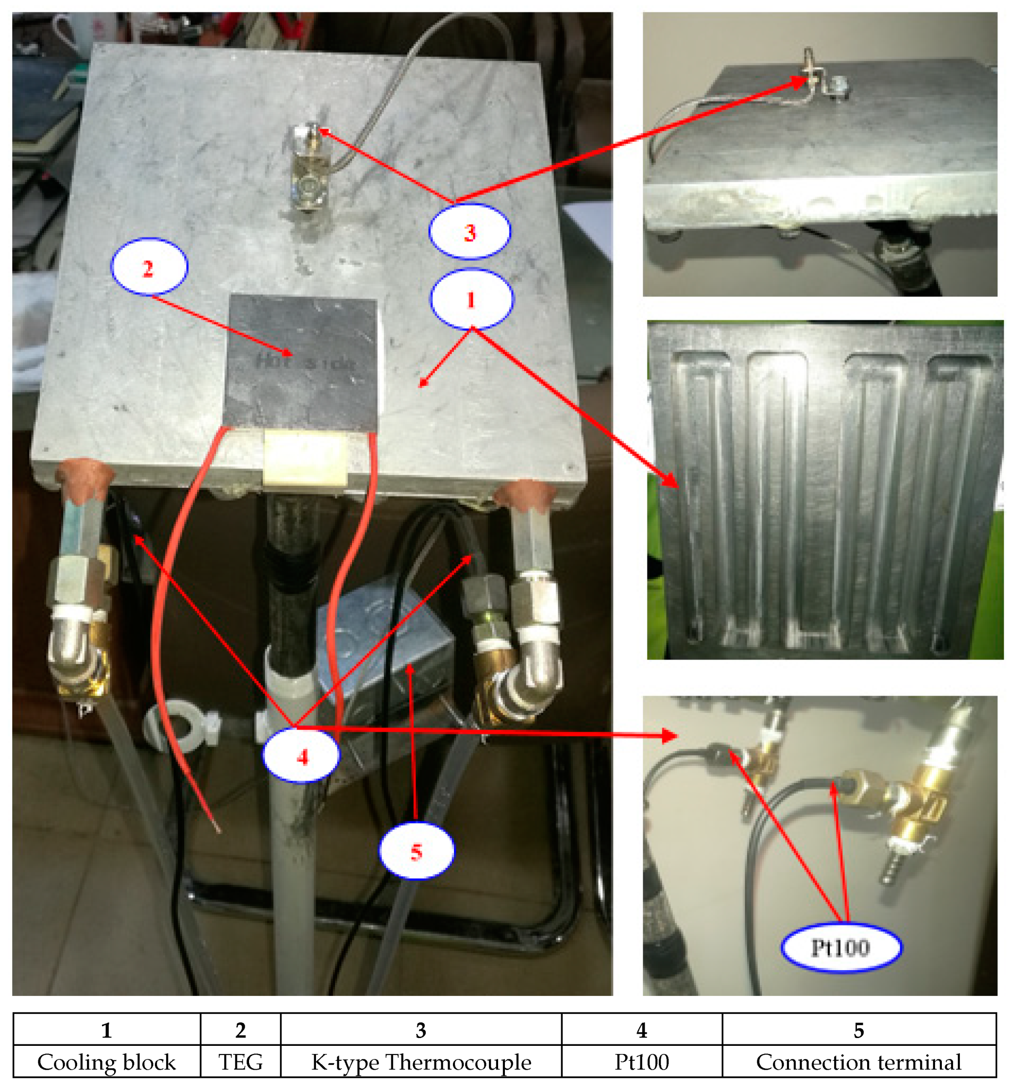
2.3. Cooling Systems

The forced-air and active-water cooling systems are studied in the present study. The details of both methods are explained in the following sections.

2.3.1. Forced-Air Cooling Method

The forced-air cooling method uses forced air as a heat carrier media, where a pin-finned heat sink is used to remove the heat from the cold side of the TEG. Figure 4 shows the geometry and photograph of the pin fin heat sink used in the present experiment.

2.3.2. Active-Water Cooling Method

The schematic diagram for the active-water cooling system with detailed components is shown in Figure 5. In active-water cooling, a forced closed-loop water cooling with a heat exchanger (radiator) system is considered. The heat exchanger is inserted before the water pump to improve the cooling efficiency by reducing the inlet temperature to the cooling block and avoiding water evaporation that will protect the pump.
Figure 6 illustrates the detailed thermoelectric module combined with a cooling block, thermocouple, and Pt100 connection. The cooling block shown on the right side of Figure 6 shows the aluminum cooling block, which has been grooved by the lathing machine, where aluminum was chosen because of its high thermal conductivity. Therefore, the heat transfer efficiency in the cooling block between water and the TEG will increase.
In the active-water cooling method for TEG, the water has been used as a working fluid because water has superior thermodynamic properties in terms of heat transport, but despite its high thermal capacity, it needs additional devices such as pumps, pipes, reservoirs, and a heat exchanger. As shown in Figure 7, the experimental setup components used in the present work are composed of (1) a storage water tank, as shown in Figure 7A, the tank is well insulated with a capacity of 75 L water, inlet makeup water, and hot water to the consumer pipe; (2) a heat exchanger (radiator), as shown in Figure 7B, the radiator fins, pipes, and the body was manufactured from copper (high thermal conductivity) with forced cross air cooling to ensure more heat will be dissipated from the water circulated to reduce the water temperature; (3) a water pump, as shown in Figure 7C, the water pump is a centrifugal type with a water flow rate of 18 L/min; and (4) pipes and fittings, indeed these pipes and fittings are covered with insulating material to prevent the effect of the surrounding temperature.

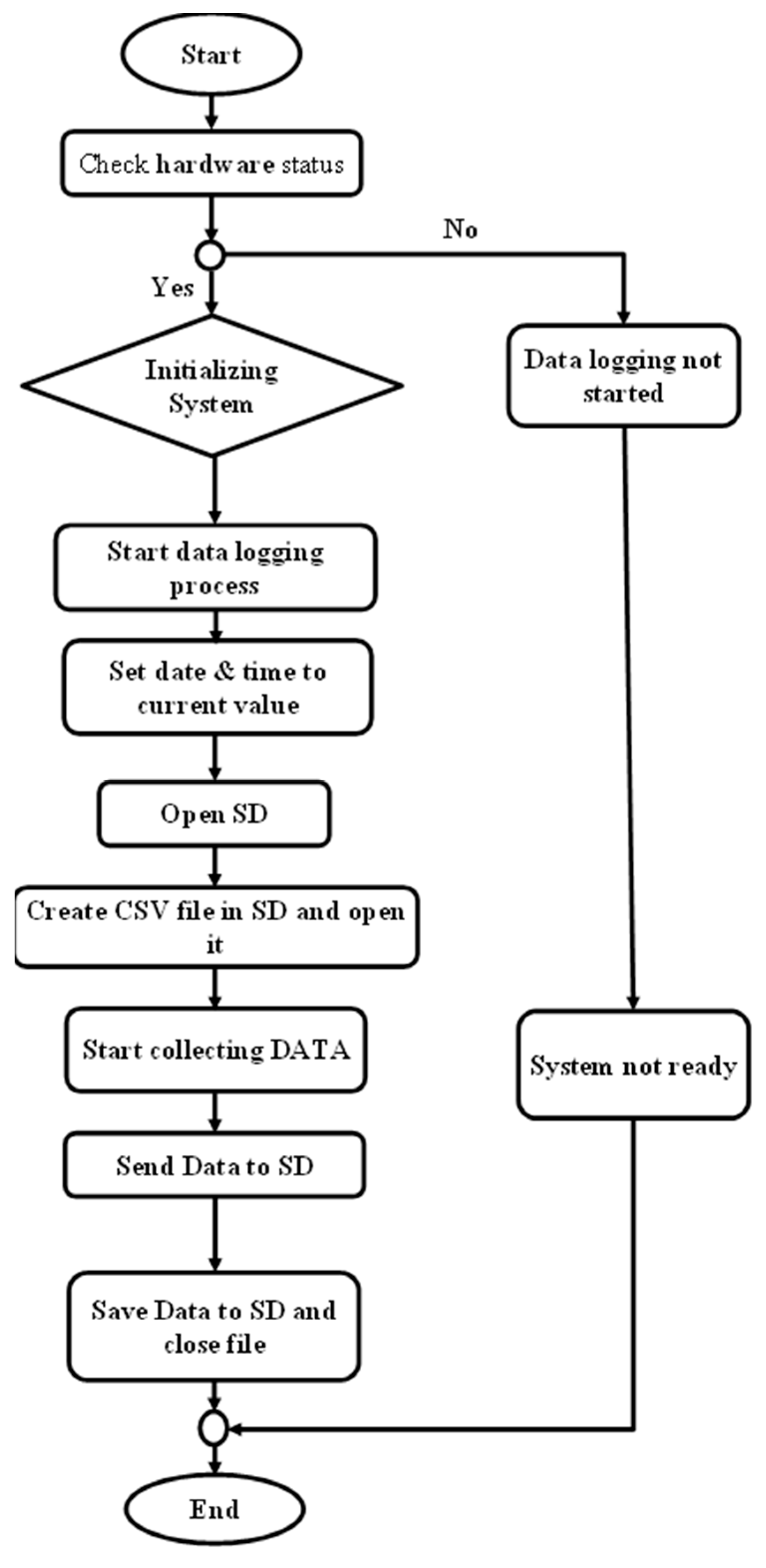
2.4. Monitoring System

Data collection is an important task during experimentation as it is required to analyze the results and verify the experiment. Therefore, it is important to read and record the experimental results for analytical purposes and future work; thus, this task was accomplished by Arduino. Arduino is an open-source software and hardware company that produces and designs a microcontroller or a set of microcontrollers built-in a single board. This board has been designed with a group of input and output ports that give the ability to interact with digital or physical objects. Additionally, this board is equipped with several communication protocols such as USB, RS232, and I2c. These protocols can be used to connect the board to a computer for loading and monitoring the program. Some protocols are used to communicate with sensors or with other microcontrollers.
The Arduino Mega 2560 board is used to record data. It is equipped with 54 digital input and output pins, 14 of which can provide plus width modulation output, 16 analog inputs, USB port, serial communication pins, and a I2c communication protocol. All details about the Arduino and the SD card, thermocouple, and voltage divider are described in detail in the supporting information in Figure 8.
Once all the shields and voltage dividers have been attached to the Arduino mega, and the program is downloaded to the controller, the data logger will be ready for physical connection to the sensors. Figure 8a,b present the data logger with all shields, connectors, and its schematic.
The measuring ranges and accuracy for temperature sensors and measurement devices used in this experiment are presented in Table A2 in Appendix A. When the sensors and TEG circuits are connected to the data logger, the system will be ready to begin data acquisition from a file. The flow chart in Figure 9 explains the process of data logging. The process starts with powering up the data logger. Once the power cycle has been finished, the program will test if all the hardware is healthy and ready to be initialized; if the system is ok, the initializing stage is completed. The date will be set to the current time to give each piece of data its own timestamp. Then, the program will check the SD card. If there is a file created or not, a new file will be created and opened, and data will start to flow from the sensor (temperatures) and TEG (voltage and current) circuits to the file as a function of time. The filed data will be stored in the form of a comma-separated format.

3. Results and Discussion

This study aims to determine the possibility of applying TEG to recover waste heat in cement plants under the TEG system’s forced-air and active-water cooling systems. The following curves for the forced-air and active-water cooling systems illustrate the relationship between the generated voltage, power, and temperature on the hot side and cold side of the TEG. Moreover, this study also demonstrates the effect of the cooling method on the generated voltage, where the readings of the voltage, ampere, and temperature have been taken as a function of the time when the system becomes stable.
The first cooling method that has been used in this work is the forced-air finned cooling method. Figure 10 illustrates the generated voltage, current, and power according to the hot- and cold-side temperatures of the TEG. The TEG average of the maximum hot-side temperature and cooling heatsink temperature is 284 °C and 29 °C, respectively. Accordingly, the maximum generated voltage, current, and power are 7.4 V, 1.6 A, and 11.84 W, respectively.
The second cooling method that has been used in this work is the closed active-water cooling method. Figure 11 illustrates the generated voltage, current, and power according to the hot- and cold-side temperatures of the TEG. The average maximum hot-side radiation and cooling water temperatures are 288 °C and 31 °C, respectively. Accordingly, the maximum generated voltage, current, and power are 7.5 V, 1.65 A, and 12.375 W, respectively.
The improvement in power for the water cooling system to the finned cooling system is about 4.4%, which is not a significant difference between the two cooling systems. Although finned cooling is simple and inexpensive compared to water cooling, water cooling is appropriate for hot-water applications.

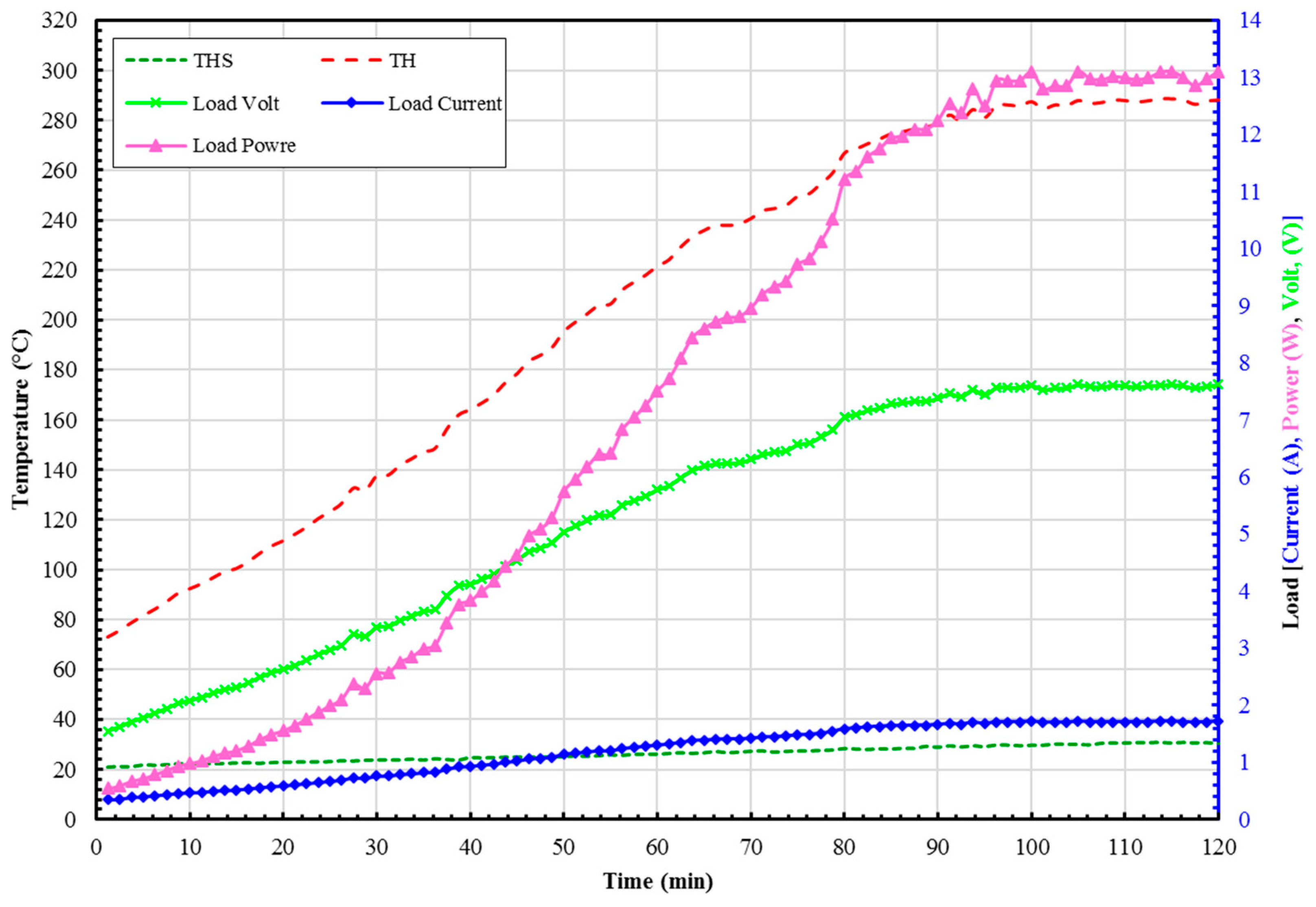
3.1. TEG Performance

The electrical power absorbed by external or load resistance will be expressed by Equation (4).
PTEG = I2 * RL = I * V
where PTEG is the load power (W), I is the load current (A), RL is the load resistance (Ω), and V is the load voltage (V).
Additionally, the thermal conversion efficacy of TEG (ηth) can simply be defined as the ratio of output power to the input heat absorbed by the TEG. Equation (5) presents this relationship.
η th , TEG = P TEG Q ˙ TEG
The input heat absorbed with TEG ( Q ˙ TEG ) was calculated theoretically for the hot and cold temperatures at the hot and cold sides, respectively, from the Equation (6) as:
Q ˙ TEG = ( T h T c ) / R tot
where the Q ˙ TEG is the transfer heat through the TEG (W), Th and Tc are the average hot and cold sides of TEG (°C), respectively, and Rtot is the total thermal resistance of TEG (°C/W). As shown in Figure 3b, the total thermal resistance can be calculated as:
Rtot = Rch + Rparallel,TEG + Rcc
Rch = Rcc = δc,sub/(kc,sub * Ac,sub)
Additionally, the parallel thermal resistances of the thermoelectric material and filler are given by [29]:
RTE = δTE/(kTE * ATE *FF)
Rfiller = δTE/(kfiller * ATE (1 − FF))
where Rch and Rcc are the ceramic thermal resistances of the hot and cold sides in (°C/W), respectively, RTE and Rfiller are the thermal resistances of the thermoelectric and filler in (°C/W), respectively, δc,sub, and δTE are the thicknesses of the ceramic substrate and thermoelectric material in (m), respectively, and kc,sub, kTE, and kfiller are the thermal conductivities of the ceramic substrate material, thermoelectric material, and filler material in (W/m °C), respectively.
The following relation is used to estimate the average cold-side temperature for cooling water.
Tave = (Twin + Twout)/2
Thus, the total thermal resistance is needed to calculate the heat flow across the module. Therefore, the total resistance Rtot is a combination of both the parallel and series resistances of the TEG components. Thus, the resultant total resistance is equal to 144.5678 °C/W for a pair of thermoelectric elements when following the lows of parallel and series.
Undoubtedly, maximizing the temperature difference across the TEG will increase the generated voltage and current. However, this deference should not exceed the maximum allowable operating temperature of TEG to avoid damaging the module. The comparison of TEG performance results under different cooling methods with commercial datasheet and effective parameters were illustrated in Table 2. Table 2 summarizes the efficiency of each cooling method that has been used during this work. The efficiency of the TEG at the optimum case is 5.85%, while the closed-loop water cooling method with a radiator has maximum efficiency, which is 4.71%, whereas the forced-air cooling method’s maximum efficiency is 4.47%.

3.2. TEG Saving and Payback Period

Moreover, the cost calculation considered that the kiln runs eleven months per year. Additionally, the electrical energy tariff for industrial application is 0.14 JD/kWh (0.197 USD/kWh), and the price of the TEG, which has been used in this study, is 6 JD (USD 8.45). The calculation considers that the kiln runs 24 h per day. Table 3 illustrates the experimental component price that has been used during the experiment. Meanwhile, to calculate an economic value for each cooling method, it is essential to list the parts and costs needed for each technique, which are illustrated in Table 3.
To compare the cost effectiveness of each cooling method, it is necessary to compare the price of the generated power. Table 4 summarizes the cost per generated power for one TEG that has been used in the experiment. Table 4 shows that when using a finned heatsink, the lowest generated power cost can be achieved by the forced-air cooling method.
As illustrated in Table 5, the payback period of the TEG system with radiator cooling water and heatsink is one year:4.0 months and 0:9.2 months, respectively.
On a large scale, the economic estimation results show the lowest payback period for the cooling water with the radiator method because it generates more power and thermal water. On the other hand, the most economical power price is the forced-air cooling method.

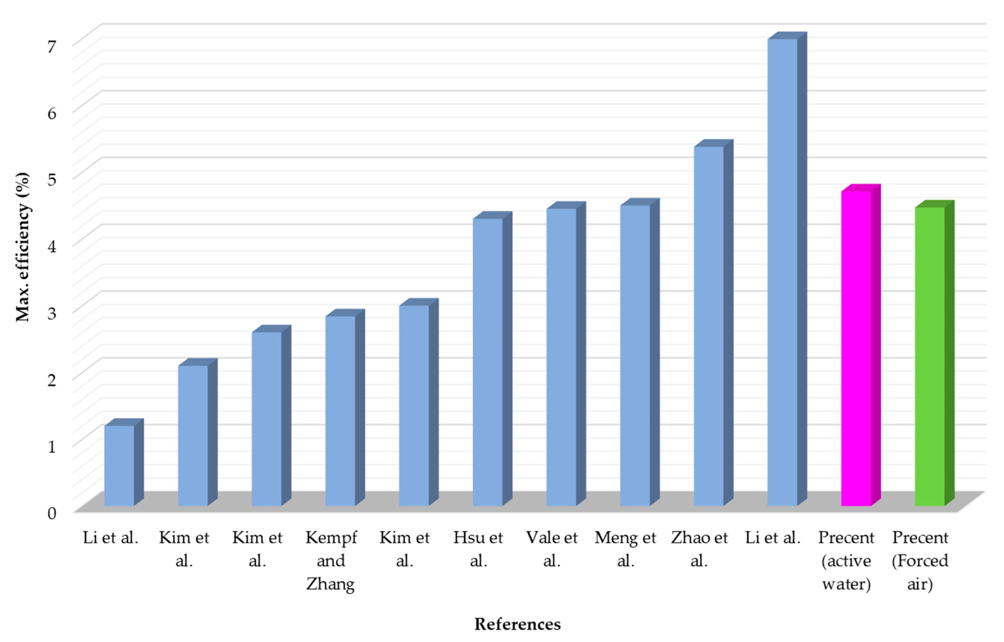
3.3. Work Validation

In Figure 12, a comparison between the current research with the earlier investigations is shown [21,24,35,36,37,38,39,40,41,42]. The figure shows the maximum efficiency of the TEG under different cooling techniques. As shown in the figure, the recommended designs are discovered among many previously established ones, indicating the appropriate outcomes for waste heat recovery application. According to Figure 12, there is no significant difference between the current study’s efficiency improvement and that discovered by Meng et al. [21], Hsu et al. [24], Vale et al. [40], and Zhao et al. [41]. However, the present study mostly relies on inexpensive components (affordable parts) and Hsu et al., Vale et al., Meng et al., and Zhao et al. employed unique material and duct combined with fins that are more expensive to produce and have greater specific characteristics. This indicates higher production and operating costs compared to the results of the current investigation.

4. Conclusions

In this research, thermal losses from the kiln shell have been described and quantified in order to determine the possibility of using it as a source of electrical power. This research was conducted to study and evaluate the performance of maximum power that can be gained from using a thermoelectric generator as a waste heat recovery tool in the rotary cement kiln. Different cooling systems for the thermoelectric generator have been studied to determine the maximum power and conversion efficiency. The main findings confirmed that the amount of heat lost from the rotary kiln shell ranges from 10 to 12.5 kW/m2 and the temperature is between 375 °C and above. This energy can be reused as useful electrical energy. A thermoelectric generator, with a high power and conversion efficiency of 17.6 W and 5.85%, respectively, is used. Two cooling systems are used with TEG forced-air finned cooling and active-water cooling. The power and efficiency of the forced-air and active-water cooling systems are 11.84 W and 4.47% and 12.375W and 4.71%, respectively. The active-water cooling method improves the power of TEG by 4.4% in comparison with forced-air cooling. The large scale energy costs of the forced air-cooling system are lower than the active-water system’s costs. Nevertheless, the thermal water heat gain is produced with water cooling, which is suitable for some applications, and the payback time is less than the other cooling method. In future work, the optimization of TEG with different parameters of cooling technology should be studies.

Author Contributions

Conceptualization, M.R.G. and T.K.M.; methodology, H.R.; validation, M.R.G., T.K.M. and M.A.A.; formal analysis, M.A.A.; investigation, H.R.; resources, M.R.G.; data curation, M.A.A.; writing—original draft preparation, M.R.G. and M.A.A.; writing—review and editing, A.A.-j. and A.M.; visualization, H.R.; supervision, M.R.G.; project administration, M.R.G.; funding acquisition, M.R.G. All authors have read and agreed to the published version of the manuscript.

Funding

This research was funded by the Deanship of Scientific Research, Al-Hussein Bin Talal University, Maan, Jordan, grant number 434/2020.

Institutional Review Board Statement

Not applicable.

Informed Consent Statement

Not applicable.

Data Availability Statement

Not applicable.

Conflicts of Interest

The authors declare no conflict of interest.

Appendix A

The TEG used in this study is presented in Figure A1. The figure shows TEG construction and the pairs of P-N junctions.
Figure A1. Thermoelectric generator (TE-MOD-18W9V-56) construction.
Sustainability 14 10146 g0a1
Table A1. Thermoelectrical module specifications (Datasheet).
ItemUnitValue
Hot-side temperature°C320
Cold-side temperature°C30
Open circuit voltage (DC)V17.7
Heat flow densityW/cm2≈9.6
AC resistance (ohms) measured under 27 at 1000 Hz°C2.3–2.5
Electrical resistivity (ρ)mΩ/m1.2
Thermal conductivity (k)W/m·K1.75
Figure of merit (ZT)(-)>1
Seebeck coefficient (α)μV/K210
Table A2. Measuring devices measuring ranges and accuracy.
Device NameMeasuring RangeAccuracyPhoto of Device
Pt 100 DS18B20−55 °C to +125 °C±0.5 °C Sustainability 14 10146 i001
Thermocouple Max66750 °C to + 1024 °C±0.25 °C Sustainability 14 10146 i002
Thermal image camera Fluke Ti100−20 °C to +250 °C±0.1 °C Sustainability 14 10146 i003
Infrared Testo 835-T2−10 °C to +1500 °C±0.01 °C Sustainability 14 10146 i004
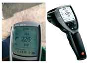
Weather conditions
(1. Temperature and 2. wind speed sensors)
−40°C–60 °C
0–50 m/s (0~100 mph)
0.1 °C
+/−0.25 m/s
Sustainability 14 10146 i005

References

  1. Gomaa, M.R.; Al-Dmour, N.; AL-Rawashdeh, H.A.; Shalby, M. Theoretical Model of a Fluidized Bed Solar Reactor Design with the Aid of MCRT Method and Synthesis Gas Production. Renew. Energy 2020, 148, 91–102. [Google Scholar] [CrossRef]
  2. Gomaa, M.R.; Mustafa, R.J.; Al-Dmour, N. Solar Thermochemical Conversion of Carbonaceous Materials into Syngas by Co-Gasification. J. Clean. Prod. 2020, 248, 119185. [Google Scholar] [CrossRef]
  3. Marashli, A.; Alfanatseh, E.; Shalby, M.; Gomaa, M.R. Modelling Single-Effect of Lithium Bromide-Water (LiBr–H2O) Driven by an Evacuated Solar Tube Collector in Ma’an City (Jordan) Case Study. Case Stud. Therm. Eng. 2022, 37, 102239. [Google Scholar] [CrossRef]
  4. Gomaa, M.R.; Mustafa, R.J.; Al-Dhaifallah, M.; Rezk, H. A Low-Grade Heat Organic Rankine Cycle Driven by Hybrid Solar Collectors and a Waste Heat Recovery System. Energy Rep. 2020, 6, 3425–3445. [Google Scholar] [CrossRef]
  5. Al-Rawashdeh, H.A.; Gomaa, M.R.; Mustafa, R.J.; Hasan, A.O. Efficiency and Exergy Enhancement of ORC Powered by Recovering Flue Gases-Heat System in Cement Industrials: A Case Study. Int. Rev. Mech. Eng. 2019, 13, 185–197. [Google Scholar] [CrossRef]
  6. Arzbaecher, C.; Parmenter, K.; Fouche, E. Industrial Waste-Heat Recovery: Benefits and Recent Advancements in Technology and Applications. In Proceedings of the ACEEE, Denver, CO, USA, 15–18 August 2007; pp. 1–2. [Google Scholar]
  7. Ayu, T.T.; Hailu, M.H.; Hagos, F.Y.; Atnaw, S.M. Energy Audit and Waste Heat Recovery System Design for a Cement Rotary Kiln in Ethiopia: A Case Study. Int. J. Automot. Mech. Eng. 2015, 12, 2983–3002. [Google Scholar] [CrossRef]
  8. Lee, H.S. Thermoelectrics: Design and Materials; Wiley: Hoboken, NJ, USA, 2016; ISBN 9781118848944. [Google Scholar]
  9. Gomaa, M.R.; Rezk, H. Passive Cooling System for Enhancement the Energy Conversion Efficiency of Thermo-Electric Generator. Energy Rep. 2020, 6, 687–692. [Google Scholar] [CrossRef]
  10. Rosa, O.C. Designing a Thermoelectric Energy Generator for Waste Heat Recovery in Heavy-Duty Diesel Engines. 2017, p. 138. Available online: https://repositorio.ufsc.br/handle/123456789/182599 (accessed on 23 March 2021).
  11. Kanagaraj, N.; Rezk, H.; Gomaa, M.R. A Variable Fractional Order Fuzzy Logic Control Based Mppt Technique for Improving Energy Conversion Efficiency of Thermoelectric Power Generator. Energies 2020, 13, 4531. [Google Scholar] [CrossRef]
  12. Wu, Q.; Hu, J. A Novel Design for a Wearable Thermoelectric Generator Based on 3D Fabric Structure. Smart Mater. Struct. 2017, 26, 045037. [Google Scholar] [CrossRef]
  13. Jung, Y.S.; Jeong, D.H.; Kang, S.B.; Kim, F.; Jeong, M.H.; Lee, K.S.; Son, J.S.; Baik, J.M.; Kim, J.S.; Choi, K.J. Wearable Solar Thermoelectric Generator Driven by Unprecedentedly High Temperature Difference. Nano Energy 2017, 40, 663–672. [Google Scholar] [CrossRef]
  14. Lu, Z.; Zhang, H.; Mao, C.; Li, C.M. Silk Fabric-Based Wearable Thermoelectric Generator for Energy Harvesting from the Human Body. Appl. Energy 2016, 164, 57–63. [Google Scholar] [CrossRef]
  15. Meng, J.H.; Wang, X.D.; Chen, W.H. Performance Investigation and Design Optimization of a Thermoelectric Generator Applied in Automobile Exhaust Waste Heat Recovery. Energy Convers. Manag. 2016, 120, 71–80. [Google Scholar] [CrossRef]
  16. Lan, S.; Yang, Z.; Chen, R.; Stobart, R. A Dynamic Model for Thermoelectric Generator Applied to Vehicle Waste Heat Recovery. Appl. Energy 2018, 210, 327–338. [Google Scholar] [CrossRef]
  17. Demir, M.E.; Dincer, I. Performance Assessment of a Thermoelectric Generator Applied to Exhaust Waste Heat Recovery. Appl. Therm. Eng. 2017, 120, 694–707. [Google Scholar] [CrossRef]
  18. Mahmoudinezhad, S.; Rezania, A.; Rosendahl, L.A. Behavior of Hybrid Concentrated Photovoltaic-Thermoelectric Generator under Variable Solar Radiation. Energy Convers. Manag. 2018, 164, 443–452. [Google Scholar] [CrossRef]
  19. Rezk, H.; Ali, Z.M.; Abdalla, O.; Younis, O.; Gomaa, M.R.; Hashim, M. Hybrid Moth-Flame Optimization Algorithm and Incremental Conductance for Tracking Maximum Power of Solar PV/Thermoelectric System under Different Conditions. Mathematics 2019, 7, 875. [Google Scholar] [CrossRef]
  20. Islam, S.; Dincer, I.; Yilbas, B.S. Development, Analysis and Assessment of Solar Energy-Based Multigeneration System with Thermoelectric Generator. Energy Convers. Manag. 2018, 156, 746–756. [Google Scholar] [CrossRef]
  21. Meng, F.; Chen, L.; Feng, Y.; Xiong, B. Thermoelectric Generator for Industrial Gas Phase Waste Heat Recovery. Energy 2017, 135, 83–90. [Google Scholar] [CrossRef]
  22. Li, G.; Zhang, G.; He, W.; Ji, J.; Lv, S.; Chen, X.; Chen, H. Performance Analysis on a Solar Concentrating Thermoelectric Generator Using the Micro-Channel Heat Pipe Array. Energy Convers. Manag. 2016, 112, 191–198. [Google Scholar] [CrossRef]
  23. Ziapour, B.M.; Saadat, M.; Palideh, V.; Afzal, S. Power Generation Enhancement in a Salinity-Gradient Solar Pond Power Plant Using Thermoelectric Generator. Energy Convers. Manag. 2017, 136, 283–293. [Google Scholar] [CrossRef]
  24. Hsu, C.T.; Won, C.C.; Chu, H.S.; Hwang, J.D. A Case Study of Thermoelectric Generator Application on Rotary Cement Furnace. In Proceedings of the Technical Papers—International Microsystems, Packaging, Assembly, and Circuits Technology Conference, IMPACT, Taipei, Taiwan, 22–25 October 2013; pp. 78–81. [Google Scholar]
  25. Luo, Q.; Li, P.; Cai, L.; Zhou, P.; Tang, D.; Zhai, P.; Zhang, Q. A Thermoelectric Waste-Heat-Recovery System for Portland Cement Rotary Kilns. J. Electron. Mater. 2015, 44, 1750–1762. [Google Scholar] [CrossRef]
  26. Sajid, M.; Hassan, I.; Rahman, A. An Overview of Cooling of Thermoelectric Devices. Renew. Sustain. Energy Rev. 2017, 78, 15–22. [Google Scholar] [CrossRef]
  27. Wu, W.N.; Liu, X.Y.; Hu, Z.; Zhang, R.; Lu, X.Y. Improving the Sustainability of Cement Clinker Calcination Process by Assessing the Heat Loss through Kiln Shell and Its Influencing Factors: A Case Study in China. J. Clean. Prod. 2019, 224, 132–141. [Google Scholar] [CrossRef]
  28. Mirhosseini, M.; Rezania, A.; Rosendahl, L. Power Optimization and Economic Evaluation of Thermoelectric Waste Heat Recovery System around a Rotary Cement Kiln. J. Clean. Prod. 2019, 232, 1321–1334. [Google Scholar] [CrossRef]
  29. Mirhosseini, M.; Rezania, A.; Rosendahl, L. Harvesting Waste Heat from Cement Kiln Shell by Thermoelectric System. Energy 2019, 168, 358–369. [Google Scholar] [CrossRef]
  30. Fan, S.; Gao, Y. Numerical Analysis on the Segmented Annular Thermoelectric Generator for Waste Heat Recovery. Energy 2019, 183, 35–47. [Google Scholar] [CrossRef]
  31. Deolalkar, S.P. Handbook for Designing Cement Plants; BS Publications: Telangana, India, 2021; ISBN 81-7800-145-4. [Google Scholar]
  32. Holderbank, Inc. Heat Balance of Kiln and Coolers and Related Topics. Cement Seminar: Comminution Engineering, Process Technology. 1993. Available online: https://pdfcoffee.com/heat-balance-of-kilns-and-coolers-and-related-topics-pdf-free.html (accessed on 24 May 2022).
  33. Enescu, D.; Virjoghe, E.O. A Review on Thermoelectric Cooling Parameters and Performance. Renew. Sustain. Energy Rev. 2014, 38, 903–916. [Google Scholar] [CrossRef]
  34. Rowe, D.; Raton London New York, B. Thermoelectrics Handbook; CRC Press: Boca Raton, FL, USA, 2018; ISBN 9781315220390. [Google Scholar]
  35. Li, Y.; Wang, S.; Zhao, Y.; Lu, C. Experimental Study on the Influence of Porous Foam Metal Filled in the Core Flow Region on the Performance of Thermoelectric Generators. Appl. Energy 2017, 207, 634–642. [Google Scholar] [CrossRef]
  36. Kim, T.Y.; Kwak, J.; Kim, B. wook Energy Harvesting Performance of Hexagonal Shaped Thermoelectric Generator for Passenger Vehicle Applications: An Experimental Approach. Energy Convers. Manag. 2018, 160, 14–21. [Google Scholar] [CrossRef]
  37. Kim, T.Y.; Kwak, J.; Kim, B. wook Application of Compact Thermoelectric Generator to Hybrid Electric Vehicle Engine Operating under Real Vehicle Operating Conditions. Energy Convers. Manag. 2019, 201, 112150. [Google Scholar] [CrossRef]
  38. Kempf, N.; Zhang, Y. Design and Optimization of Automotive Thermoelectric Generators for Maximum Fuel Efficiency Improvement. Energy Convers. Manag. 2016, 121, 224–231. [Google Scholar] [CrossRef]
  39. Kim, T.Y.; Negash, A.A.; Cho, G. Experimental Study of Energy Utilization Effectiveness of Thermoelectric Generator on Diesel Engine. Energy 2017, 128, 531–539. [Google Scholar] [CrossRef]
  40. Vale, S.; Heber, L.; Coelho, P.J.; Silva, C.M. Parametric Study of a Thermoelectric Generator System for Exhaust Gas Energy Recovery in Diesel Road Freight Transportation. Energy Convers. Manag. 2017, 133, 167–177. [Google Scholar] [CrossRef]
  41. Zhao, Y.; Wang, S.; Ge, M.; Liang, Z.; Liang, Y.; Li, Y. Performance Investigation of an Intermediate Fluid Thermoelectric Generator for Automobile Exhaust Waste Heat Recovery. Appl. Energy 2019, 239, 425–433. [Google Scholar] [CrossRef]
  42. Li, B.; Huang, K.; Yan, Y.; Li, Y.; Twaha, S.; Zhu, J. Heat Transfer Enhancement of a Modularised Thermoelectric Power Generator for Passenger Vehicles. Appl. Energy 2017, 205, 868–879. [Google Scholar] [CrossRef]
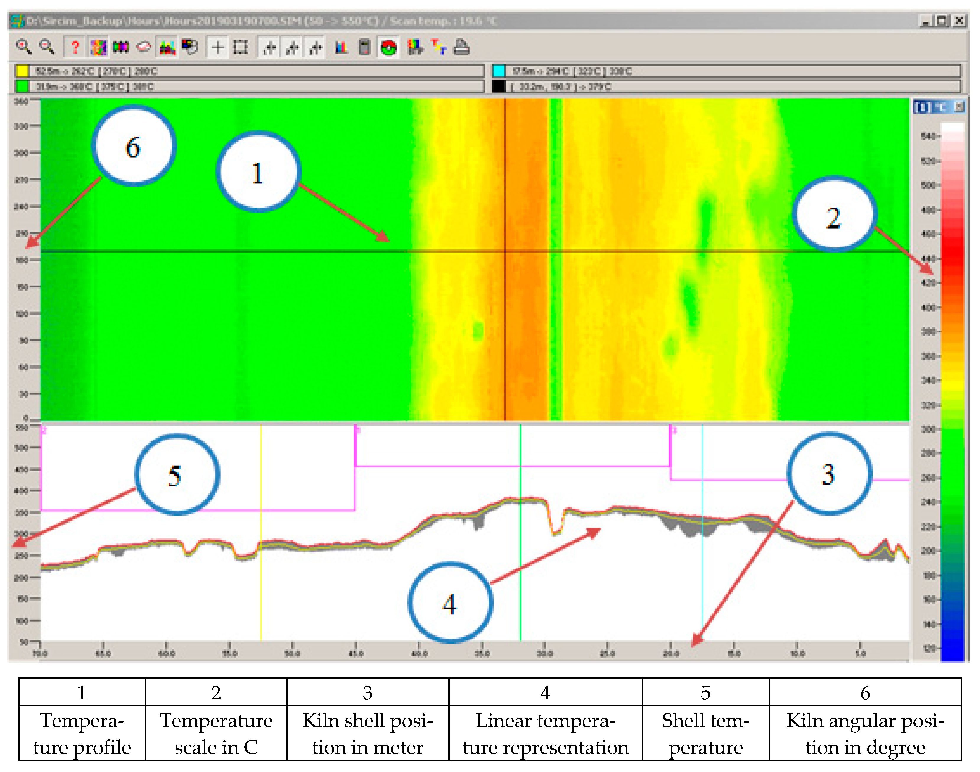
Figure 1. Cement kiln. (A) Outside the rotary kiln; (B) Inner refractory inside a rotary kiln; (C) Inside the kiln burner.
Sustainability 14 10146 g001
Figure 2. Thermal profile for the outer kiln surface.
Sustainability 14 10146 g002
Figure 3. TEG energy conversion mechanism. (a) Components of TEG and (b) thermal resistance circuit.
Sustainability 14 10146 g003
Figure 4. Finned heat sink, (a) Heat sink system, (b) TEG, (c) Nail heat sink, and (d) Cooling fan.
Sustainability 14 10146 g004
Figure 5. Closed-loop cooling system with heat exchanger.
Sustainability 14 10146 g005
Figure 6. Detailed TEG, water cooling block, and thermocouple components.
Sustainability 14 10146 g006
Figure 7. The active-water cooling components. (A) Storage water tank, (B) heat exchanger, and (C) water pump.
Sustainability 14 10146 g007
Figure 8. Data logger. (a) The complete assembly and (b) detailed connection.
Sustainability 14 10146 g008
Figure 9. Data acquisition sequence.
Sustainability 14 10146 g009
Figure 10. Forced-air cooling method affects the output voltage, current, and power. (TH: Hot-side temperature; THS: Heatsink temperature).
Sustainability 14 10146 g010
Figure 11. Closed water cooling with the radiator method affects the output voltage, current, and power. (TH: hot-side temperature; Tave: average water temperature; Twin: inlet water temperature; Twout: outlet water temperature).
Sustainability 14 10146 g011
Figure 12. Comparing the results of the current study in relation to the previously proposed designs (Meng et al. [21], Hsu et al. [24], Li et al. [35], Kim et al. [36], Kim et al. [37], Kempf and Zhang [38], Kim et al. [39], Vale et al. [40], Zhao et al. [41], and Li et al. [42]).
Sustainability 14 10146 g012
Table 1. Radiation and convection heat loss calculation for positions 30 m to 35 m was measured on 19 November 2020.
Kiln Shell Segment Position, (m)Temp., (°C)Emissivity, ε
(-)
Wind Speed
(m/s)
αtot
(W/m2·°C)
Q ˙ t o t
(kW)
FromTo
30313770.92.433.4821167.5631
31323840.92.434.12683174.1668
32333830.92.434.03405173.2122
33343780.92.433.57353168.4953
34353740.92.433.20911164.7885
Table 2. Conversion efficiency for different cooling methods.
Cooling MethodAverage Measured DataCalculated Data
Th (°C)Tc (°C)Vmax (V)Imax (A)Pmax (W) Q ˙ T E G   ( W ) ηTEG
(%)
Datasheet32030.08.8217.63015.85
Closed water with radiator288.031.07.51.6512.375262.954.71
Forced-air cooling (Heatsink)28429.07.41.611.84265.034.47
Table 3. Experimental component price.
PartsQuantityUnit Price (JD)Part List for Each Cooling Method
Water CoolingAir Cooling
TEG16AA
Water Pump15ANA
Pipe and fitting and cooling block14ANA
Water tank 13ANA
Finned heatsink13NAA
Fan 2NAA
Radiator 12ANA
Cost without sensors (JD) 20 JD (28 $)11 JD (15.7 $)
A: Available, NA: Not available, JD: Jordan Dinar.
Table 4. Generated power cost.
Cooling MethodPower Generated
(W)
Parts Cost
(USD)
Watt Price
(USD/W)
Cooling water with a radiator12.375282.2
Heatsink 11.8415.70.75
Table 5. Payback period.
Cooling MethodSaving Power
(kWh/Year)
Saving Power Cost
(USD/Year)
Payback Period
(Year:Month)
Cooling water with radiator108.4021.361:4.0
Forced-air cooling103.7220.430:9.2
Publisher’s Note: MDPI stays neutral with regard to jurisdictional claims in published maps and institutional affiliations.

