
Development of a Sharing Concept for Industrial Compost Turners Using Model-Based Systems Engineering, under Consideration of Technical and Logistical Aspects


Abstract
:1. Introduction
1.1. Megatrend Sharing Economy
1.2. Sharing Concepts and Composting
1.3. Methodical Approach to the Development of Sharing Concepts
1.4. The Resulting Research Gap
1.5. Research Question
- (1)
- How can a sharing concept be developed for compost turners (from a technical perspective)?
- (2)
- Which boundary conditions must be considered? (Transportation routes, Transportation time, maximum processing time per composting plant, …)?
2. Methods, Approach and Tools
The formalised application of modelling to support system requirements, design, analysis, verification and validation activities beginning in the conceptual design phase and continuing throughout development and later life cycle phases [42].
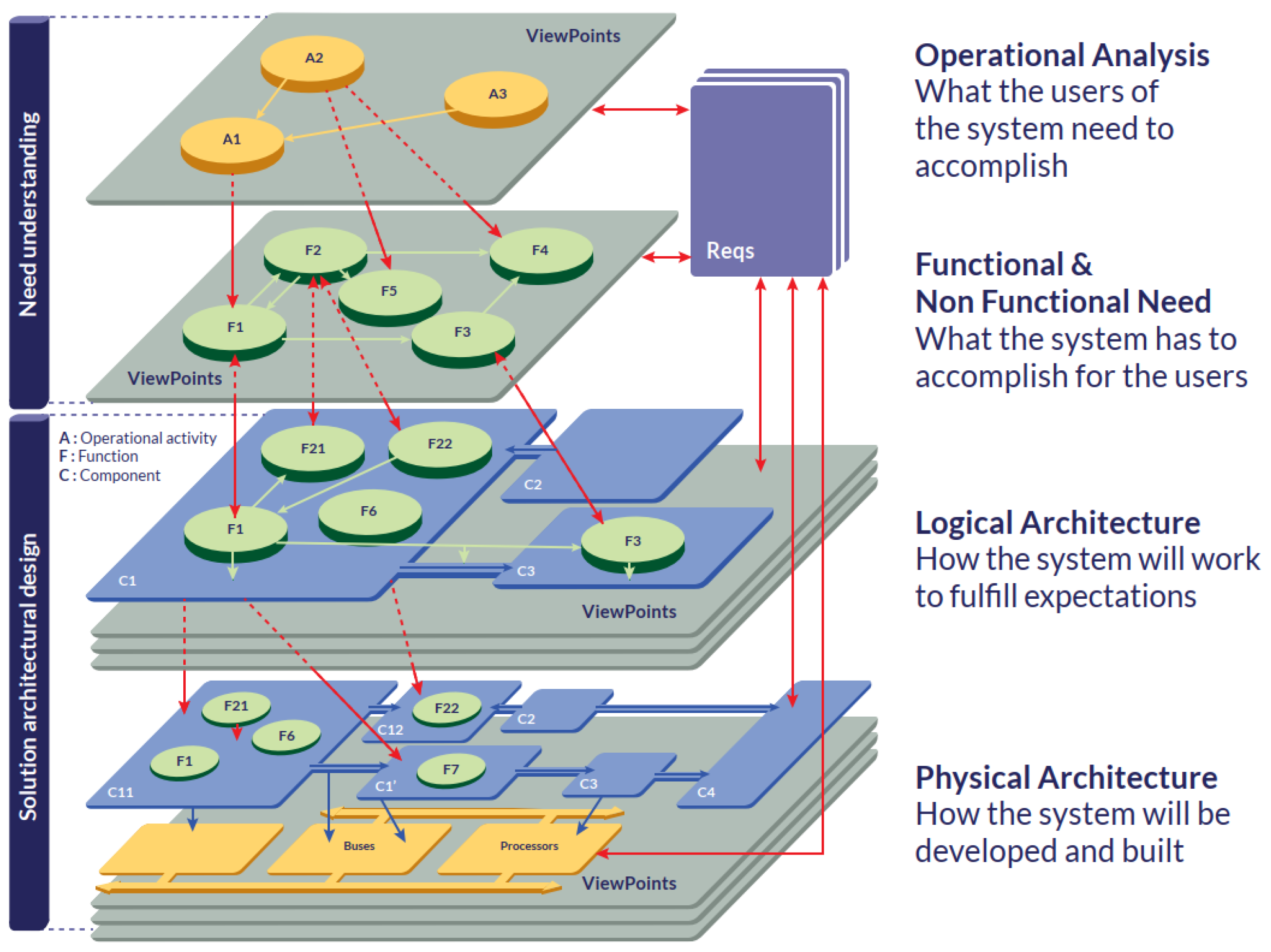
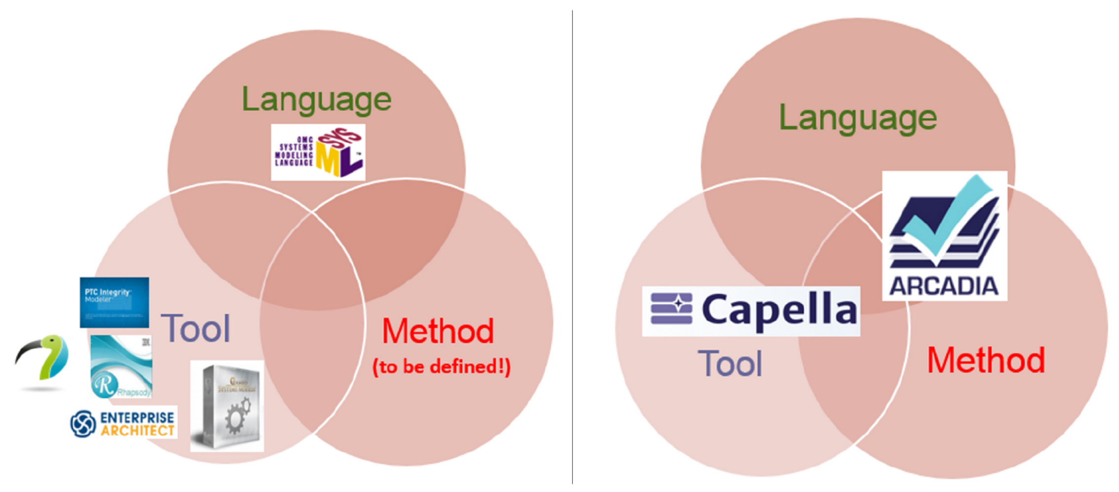
2.1. The ARCADIA Method
ARCADIA is thus a structured engineering method for defining and verifying the architecture of complex systems. It promotes collaborative work among all key players, often in large numbers, from the engineering (or definition) phase of the system and subsystems, until their Independent Verification and Validation (IVV) [50].
The Design of ARCADIA Using Four Layers/Working Levels
2.2. The Capella Tool
2.3. Representation of a System versus Representation of the Development of a System
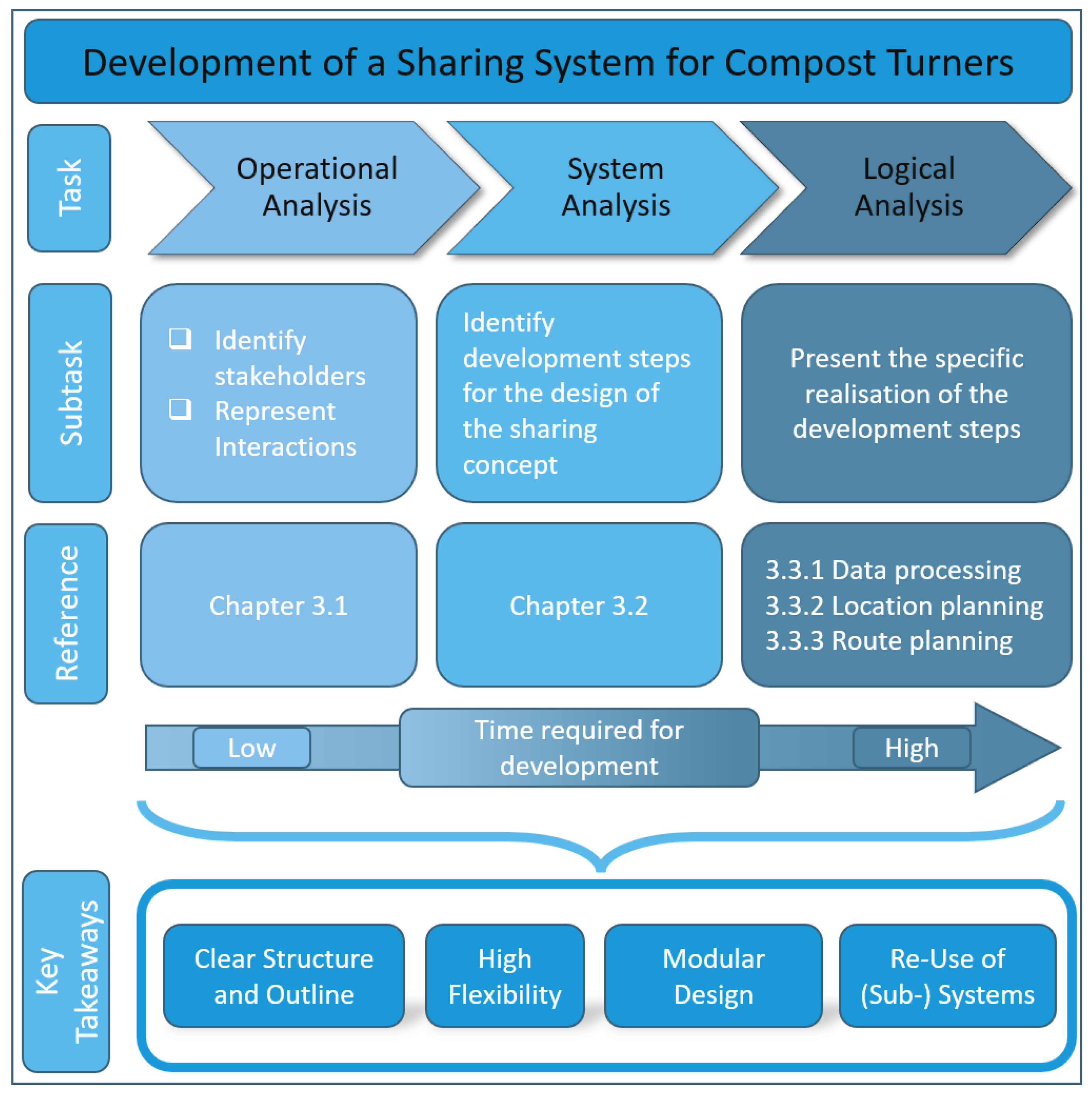
3. Development, Applications and Results
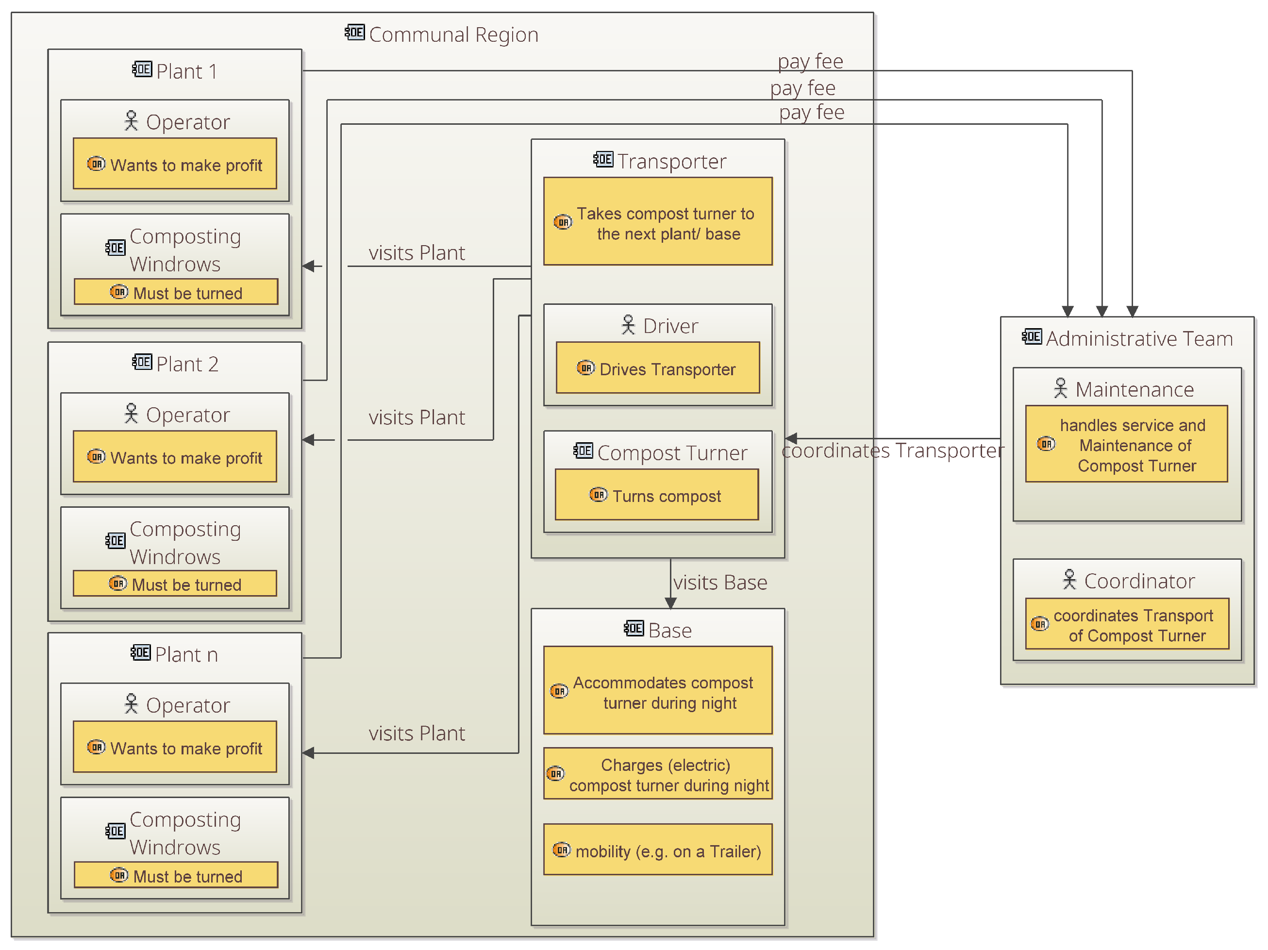
3.1. Operational Analysis—Identifying Stakeholders
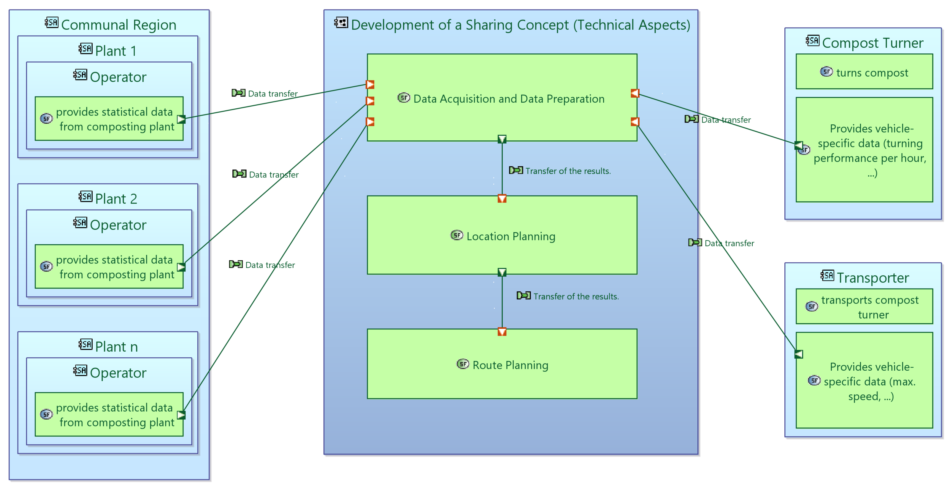
3.2. System Analysis—From Plant Locations to Route Planning
- Data acquisition and data preparation
- Location planning;
- Route planning.
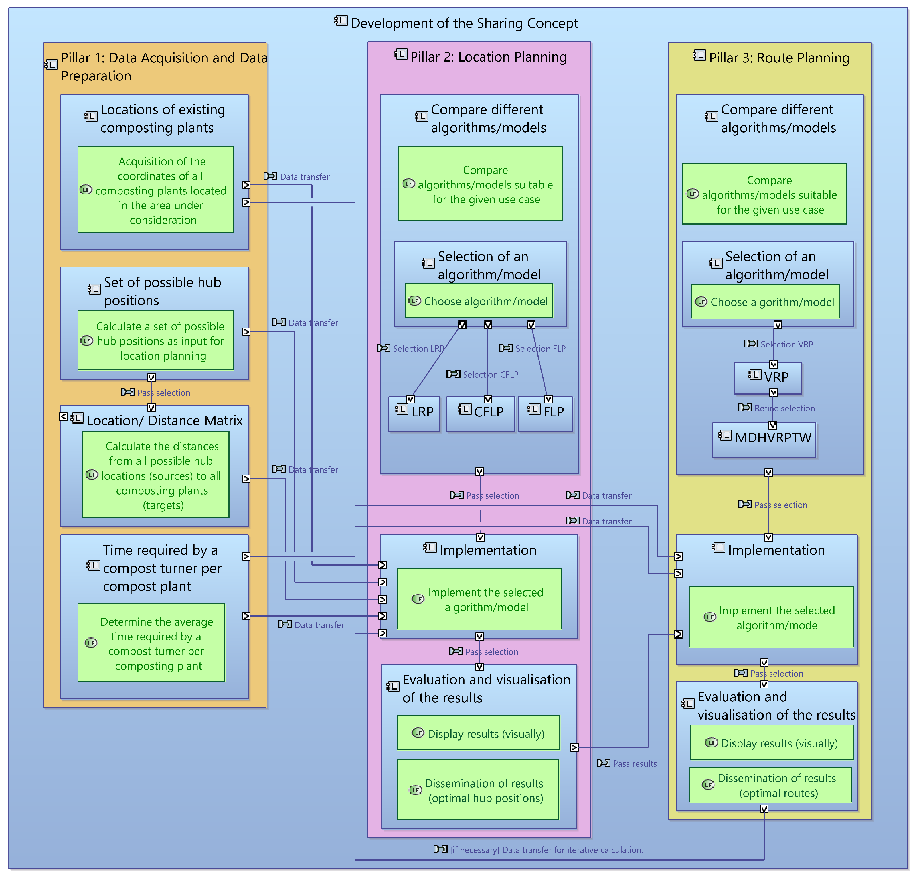
3.3. Logical Analysis—Developing the Sharing Concept as a System of Systems
3.3.1. Pillar 1: Data Acquisition and Data Preparation
- “Locations of existing composting plants”;
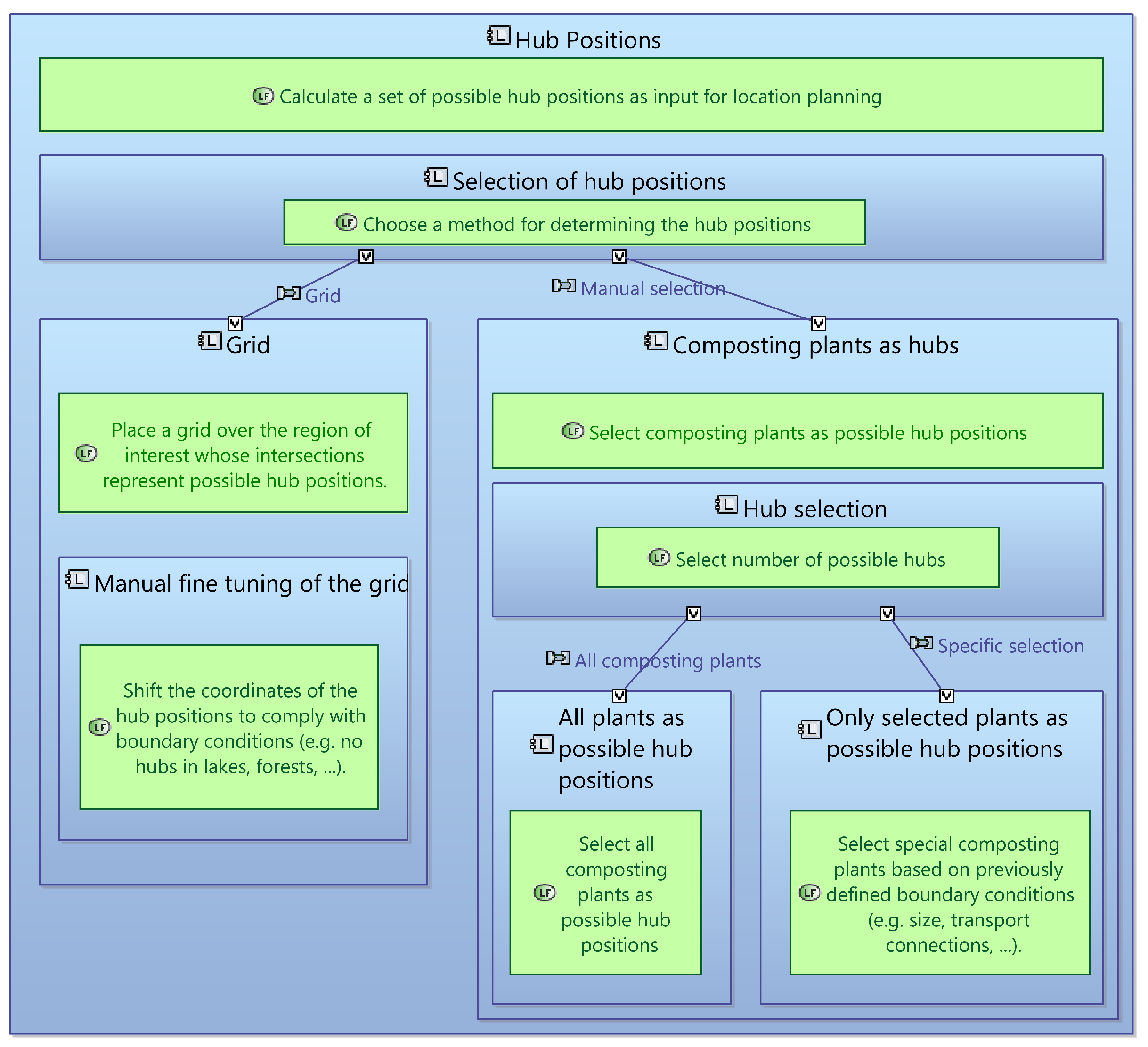
- “Set of possible hub positions”;
- “Location/distance matrix”;
- “Time requirement of a compost turner per compost site”.
3.3.2. Pillar 2: Location Planning
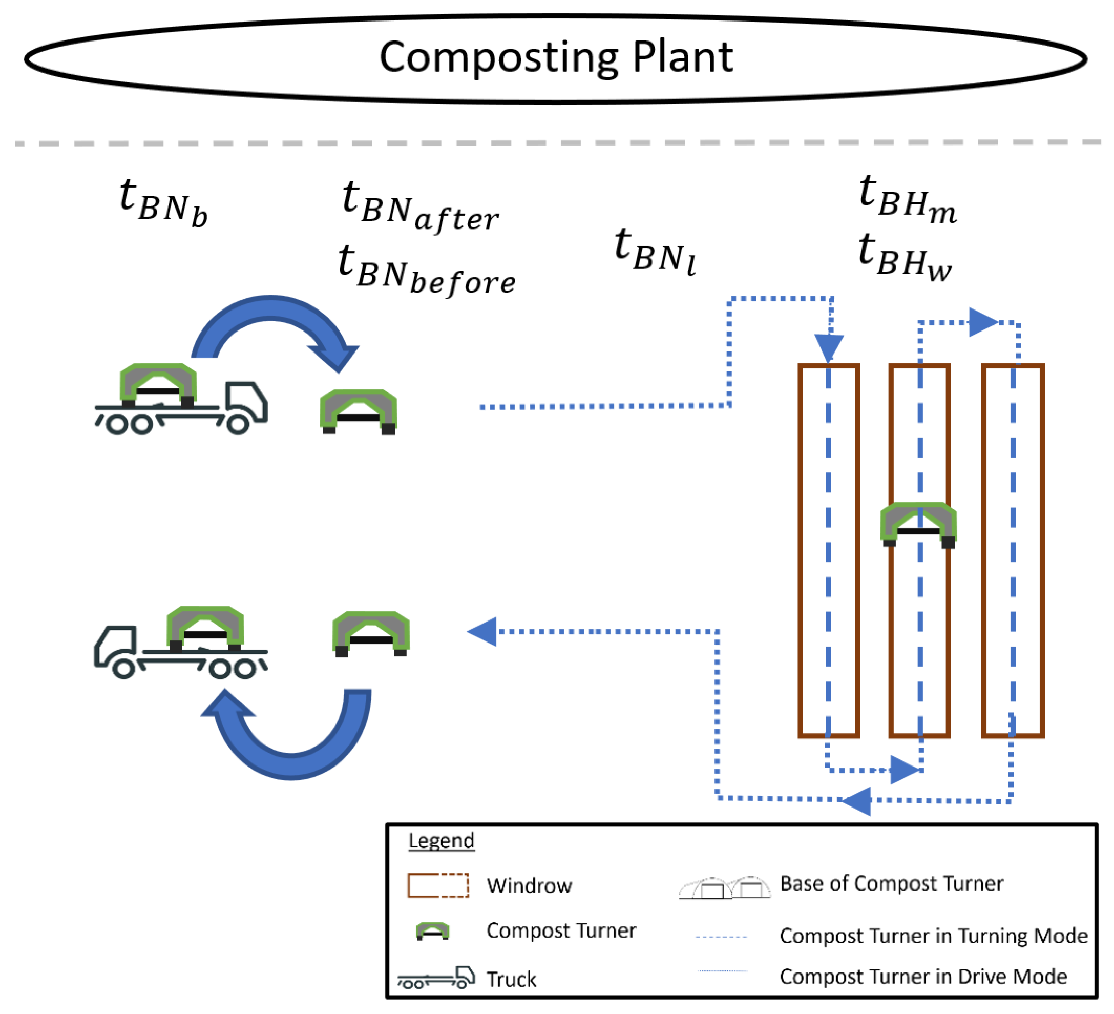
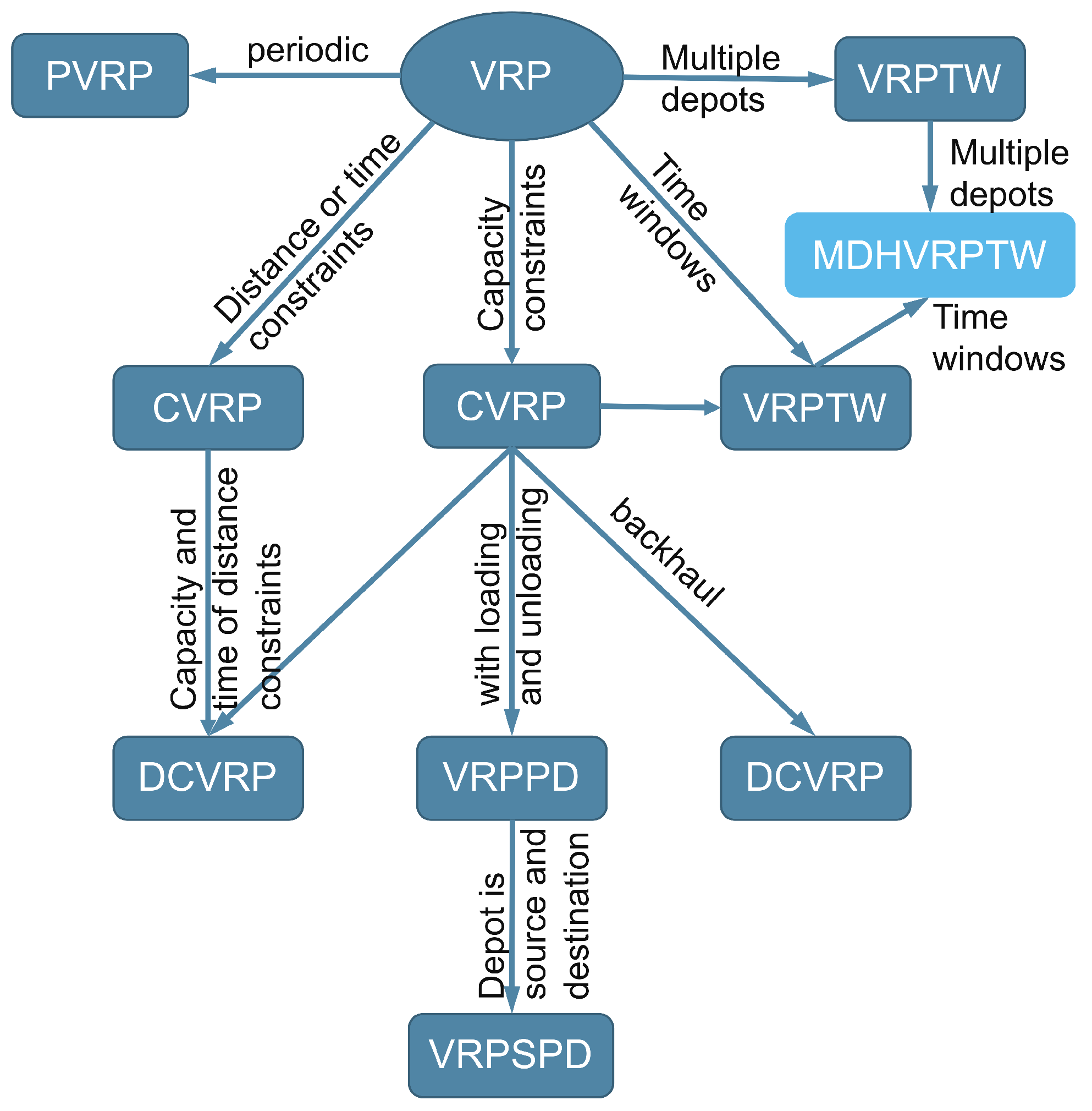
3.3.3. Pillar 3: Route Planning
4. Discussion
5. Industrial Application and Further Research
Author Contributions
Funding
Institutional Review Board Statement
Informed Consent Statement
Data Availability Statement
Acknowledgments
Conflicts of Interest
Appendix A

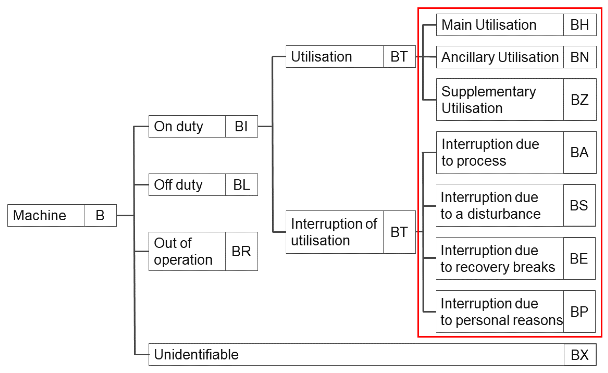
| No. | Processing Times | Abbreviation | Dependent on Parameters |
|---|---|---|---|
| BH | Main utilisation | ||
| 1. | Turning | , ; | |
| BN | Ancillary utilisation | ||
| 2. | Transfer between windrows | , ; | |
| 3. | Transfer between windrow and truck | , ; | |
| 4. | Transport between composting plants | , ; | |
| 5. | Charging the battery of the compost turner | (, ), ; | |
| 6. | Loading/unloading the compost turner on the truck | ||
| 7. | Preparing for turning process | ||
| 8. | Preparation after turning process | ||
| 9. | Planned waiting times | ||
| BZ | Supplementary utilisation | ||
| 10. | Delays in transport | ||
| 11. | Unpredictable conditions/events at the composting plant | ||
| BA | Interruption due to process | ||
| 12. | Waiting time for workers after turning process | ||
| 13. | Modifications to the compost turner | ||
| 14. | Waiting time for truck | ||
| BS | Interruption due to disturbance | ||
| 15. | Maintenance work | ||
| 16. | Refuelling truck | ||
| 17. | Organisational tasks | ||
| BE | Interruption due to recovery breaks | ||
| BP | Interruption due to personal reasons | ||
| 18. | Unscheduled breaktimes of the operator | ||
| BL | Off duty | ||
| 19. | Major repair work | ||
| 20. | Service | ||
| 21. | Modifications and updates | ||
| BR | Out of operation | ||
| 22. | unused |
References
- Belk, R. Sharing. J. Consum. Res. 2009, 36, 715–734. [Google Scholar] [CrossRef]
- Acquier, A.; Daudigeos, T.; Pinkse, J. Promises and Paradoxes of the Sharing Economy: An Organizing Framework. Technol. Forecast. Soc. Change 2017, 125, 1–10. [Google Scholar] [CrossRef]
- Frenken, K.; Schor, J. Putting the Sharing Economy into Perspective. Environ. Innov. Soc. Transit. 2017, 23, 3–10. [Google Scholar] [CrossRef]
- Zvolska, L.; Voytenko Palgan, Y.; Mont, O. How Do Sharing Organisations Create and Disrupt Institutions? Towards a Framework for Institutional Work in the Sharing Economy. J. Clean. Prod. 2019, 219, 667–676. [Google Scholar] [CrossRef]
- Huarng, K.H. Entrepreneurship for Long-term Care in Sharing Economy. Int. Entrep. Manag. J. 2018, 14, 97–104. [Google Scholar] [CrossRef]
- Leeuw, T.; Gössling, T. Theorizing Change Revisited: An Amended Process Model of Institutional Innovations and Changes in Institutional Fields. J. Clean. Prod. 2016, 135, 435–448. [Google Scholar] [CrossRef]
- Hossain, M. Sharing Economy: A Comprehensive Literature Review. Int. J. Hosp. Manag. 2020, 87, 102470. [Google Scholar] [CrossRef]
- Wilhelms, M.P.; Henkel, S.; Falk, T. To Earn Is Not Enough: A Means-End Analysis to Uncover Peer-Providers’ Participation Motives in Peer-to-Peer Carsharing. Technol. Forecast. Soc. Chang. 2017, 125, 38–47. [Google Scholar] [CrossRef]
- Botsman, R.; Rogers, R. What Is Mine Is Yours: How Collaborative Consumption Is Changing the Way We Live; Collins: Glasgow, UK, 2011. [Google Scholar]
- Mont, O.; Palgan, Y.V.; Bradley, K.; Zvolska, L. A Decade of the Sharing Economy: Concepts, Users, Business and Governance Perspectives. Int. J. Hosp. Manag. 2017, 269, 122215. [Google Scholar] [CrossRef]
- Artz, G.; Colson, G.; Ginder, R. A Return of the Threshing Ring? A Case Study of Machinery and Labor-Sharing in Midwestern Farms. J. Agric. Appl. Econ. 2015, 42, 805–819. [Google Scholar] [CrossRef] [Green Version]
- Lagerkvist, C.J.; Hansson, H. Machinery-Sharing in the Presence of Strategic Uncertainty: Evidence from Sweden. Agric. Econ. 2015, 43, 113–123. [Google Scholar] [CrossRef]
- Larsén, K. Effects of Machinery-Sharing Arrangements on Farm Efficiency: Evidence from Sweden. Agric. Econ. 2010, 41, 497–506. [Google Scholar] [CrossRef]
- European Commission. 2030 Climate Target Plan; European Union: Luxembourg, 2022. [Google Scholar]
- European Commission. Circular Economy Action Plan—For a Cleaner and More Competitive Europe; Publications Office of the European Union: Luxembourg, 2020. [Google Scholar]
- European Commission. Directive (EU) 2018/852 of the European Parliament and of the Council of 30 May 2018 Amending Directive 94/62/EC on Packaging and Packaging Waste; European Union: Luxembourg, 2018. [Google Scholar]
- Neubauer, C. Die Bestandsaufnahme der Abfallwirtschaft in Österreich; Bundesministerium für Klimaschutz, Umwelt, Energie, Mobilität, Innovation und Technologie: Abteilung V/3: Abfallwirtschaftsplanung, Abfallbehandlung und Altlastensanierung; BMK: Vienna, Austria, 2022. [Google Scholar]
- Viaene, J.; Van Lancker, J.; Vandecasteele, B.; Willekens, K.; Bijttebier, J.; Ruysschaert, G.; De Neve, S.; Reubens, B. Opportunities and barriers to on-farm composting and compost application: A case study from northwestern Europe. Waste Manag. 2016, 48, 181–192. [Google Scholar] [CrossRef] [PubMed]
- Dunst, G. Kompostierung und Erdenherstellung: Praxisbuch und Anleitung für Hausgarten, Landwirtschaft, Kommune und Profi, 1st ed.; Sonnenerde: Riedlingsdorf, Austria, 2015. [Google Scholar]
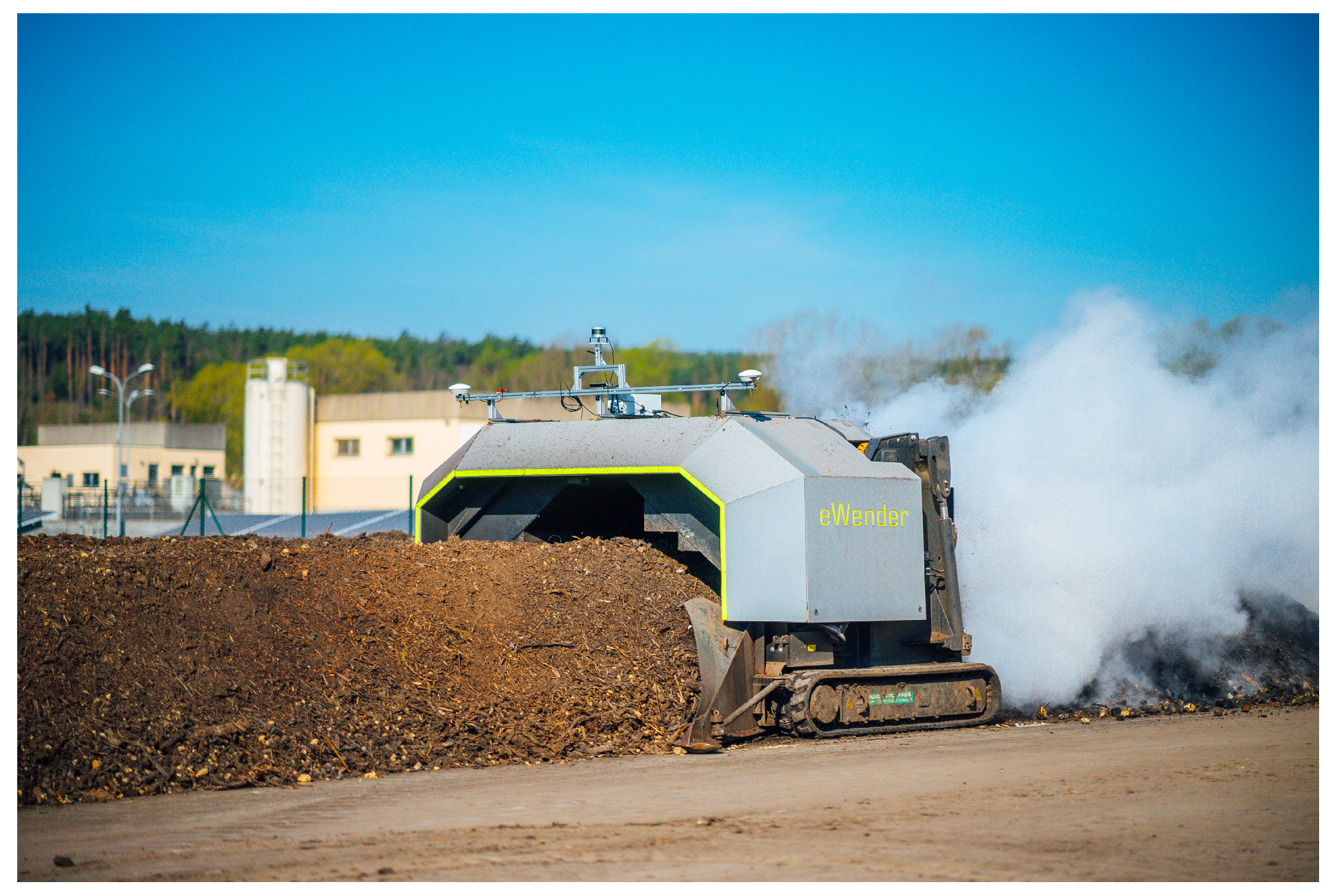
- Schedler, M.; Ortner-Pichler, A.; Reitbauer, E.; Mahringer, G.; Landschützer, C. Interdisciplinary System Simulation of a Tracked Compost Turner. Procedia Manuf. 2020, 51, 1005–1013. [Google Scholar] [CrossRef]
- Reitbauer, E.; Schmied, C.; Wieser, M. Autonomous Navigation Module for Tracked Compost Turners; IEEE: New York, NY, USA, 2020; p. 10. [Google Scholar] [CrossRef]
- Reitbauer, E.; Schmied, C.; Schedler, M. Integrated Navigation for Tracked Compost Turners Using GNSS, INS, Odometers, Stereo Camera and 3D Map; Institute of Navigation: Manassas, VA, USA, 2020. [Google Scholar] [CrossRef]
- Reitbauer, E.; Schmied, C. Performance Analysis of GNSS/INS/VO/Odometry Sensor Fusion Algorithms for Tracked Agricultural Vehicles; Institute of Navigation: Manassas, VA, USA, 2021; p. 3262. [Google Scholar] [CrossRef]
- Maleki, E. A Systems Engineering-based Semantic Model to Support “Product-Service System” Life Cycle. Ph.D. Thesis, École centrale de Nantes, Nantes, France, 2018. [Google Scholar]
- Hick, H.; Bajzek, M.; Faustmann, C. Definition of a System Model for Model-Based Development. SN Appl. Sci. 2019, 1, 1074. [Google Scholar] [CrossRef]
- Hick, H.; Küpper, K.; Sorger, H. Systems Engineering for Automotive Powertrain Development, 1st ed.; Springer International Publishing: Berlin/Heidelberg, Germany, 2021. [Google Scholar]
- Angelopoulos, A.; Gavalas, D.; Konstantopoulos, C.; Kypriadis, D.; Pantziou, G. An Optimization Model for the Strategic Design of a Bicycle Sharing System: A Case Study in the City of Athens; Association for Computing Machinery: New York, NY, USA, 2016; p. 6. [Google Scholar] [CrossRef]
- Martinez, L.; Caetano, L.; Eiró, T.; Cruz, F. An Optimisation Algorithm to Establish the Location of Stations of a Mixed Fleet Biking System: An Application to the City of Lisbon. Procedia Soc. Behav. Sci. 2012, 54, 513–524. [Google Scholar] [CrossRef] [Green Version]
- Nikiforiadis, A.; Aifadopoulou, G.; Salanova Grau, J.M.; Boufidis, N. Determining the Optimal Locations for Bike-Sharing Stations: Methodological Approach and Application in the City of Thessaloniki, Greece. Transp. Res. Procedia 2021, 52, 557–564. [Google Scholar] [CrossRef]
- Saharidis, G.; Fragkogios, A.; Zygouri, E. A Multi-Periodic Optimization Modeling Approach for the Establishment of a Bike Sharing Network: A Case Study of the City of Athens. In Proceedings of the International MultiConference of Engineers and Computer Scientists (IMECS 2014), Hongkong, China, 12–14 March 2014; Volume 2210. [Google Scholar]
- Wolfley, J.L. Machinery Sharing by Agribusiness Firms: Methodology, Application, and Simulation. Ph.D. Thesis, Texas A&M University, College Station, TX, USA, 2008. [Google Scholar]
- Rakhra, M. A Study of Machinery and Equipment Used by Farmers to Develop an Uberized Model for Renting and Sharing. Mater. Today Proc. 2021; in press. [Google Scholar]
- Rakhra, M.; Singh, R.; Lohani, T.K.; Shabaz, M. Metaheuristic and Machine Learning-Based Smart Engine for Renting and Sharing of Agriculture Equipment. Math. Probl. Eng. 2021, 2021, e5561065. [Google Scholar] [CrossRef]
- Başarık, A.; Yıldırım, S. A Case Study of Sharing Farm Machinery in Turkey. Int. J. Nat. Eng. Sci. 2015, 9, 1–5. [Google Scholar]
- McGinnis, L.; Schmidt, M.; Spee, D. Model Based Systems Engineering and Warehouse Design. In Efficiency and Innovation in Logistics; Springer: Cham, Switzerland, 2014; pp. 161–178. [Google Scholar] [CrossRef]
- Mousavi, B.A.; Heavey, C.; Azzouz, R.; Ehm, H.; Millauer, C.; Knobloch, R. Use of Model-Based System Engineering Methodology and Tools for Disruption Analysis of Supply Chains: A Case in Semiconductor Manufacturing. J. Ind. Inf. Integr. 2015, 28, 100335. [Google Scholar] [CrossRef]
- Navarro, N.; Horvath, L.; Salado, A. Design of an IoT System for the Palletized Distribution Supply Chain with Model-Based Systems Engineering Tools. Systems 2022, 10, 4. [Google Scholar] [CrossRef]
- Liu, J.; Liu, J.; Zhuang, C.; Liu, Z.; Miao, T. Construction Method of Shop-Floor Digital Twin Based on MBSE. J. Manuf. Syst. 2021, 60, 93–118. [Google Scholar] [CrossRef]
- Madni, A.M.; Purohit, S. Augmenting MBSE with Digital Twin Technology: Implementation, Analysis, Preliminary Results, and Findings; IEEE: New York, NY, USA, 2021; pp. 2340–2346. [Google Scholar] [CrossRef]
- Sprock, T.A. A Model-Driven Approach to Interoperability Between Simulation and Optimization for Production and Logistics Systems; NIST: Gaithersburg, MD, USA, 2020. [Google Scholar]
- Scott, W.; Fullalove, R.; Arabian, G.; Campbell, P. Case Study: A Model Based Systems Engineering (MBSE) Framework for Characterising Transportation Systems Over the Full Life Cycle. INCOSE Int. Symp. 2016, 26, 916–932. [Google Scholar] [CrossRef]
- INCOSE. Systems Engineering Vision 2020; International Council on Systems Engineering (INCOSE): San Diego, CA, USA, 2020. [Google Scholar]
- Walden, D.D.; Roedler, G.J.; Forsberg, K.J.; Hamelin, R.D.; Shortell, T.M. INCOSE Systems Engineering Handbook: A Guide for System Life Cycle Processes and Activities, 4th ed.; Wiley: Hoboken, NJ, USA, 2015. [Google Scholar]
- Long, D.A.; Scott, Z.B. A Primer for Model-Based Systems Engineering; Lulu Press: Morrisville, NC, USA, 2011. [Google Scholar]
- Weilkiens, T. Systems Engineering Mit SysML/UML: Anforderungen, Analyse, Architektur; Dpunkt Verlag: Heidelberg, Germany, 2014. [Google Scholar]
- IBM Knowledge Center. The Harmony Process—IBM Documentation; IBM: Armonk, NY, USA, 2021. [Google Scholar]
- Dori, D. Model-Based Systems Engineering with OPM and SysML, 1st ed.; Springer: Berlin/Heidelberg, Germany, 2016; p. 411. [Google Scholar] [CrossRef]
- Roques, P. Systems Architecture Modeling with the Arcadia Method: A Practical Guide to Capella; Elsevier: Amsterdam, The Netherlands, 2017. [Google Scholar]
- Bajzek, M.; Fritz, J.; Hick, H.; Maletz, M.; Faustmann, C.; Stieglbauer, G. Model Based Systems Engineering Concepts. In Systems Engineering for Automotive Powertrain Development; Hick, H., Küpper, K., Sorger, H., Eds.; Powertrain; Springer: Cham, Switzerland, 2020. [Google Scholar] [CrossRef]
- Voirin, J.L. Model-Based System and Architecture Engineering with the Arcadia Method; Implementation of Model Based System Engineering Set; Elsevier: Amsterdam, The Netherlands, 2017. [Google Scholar]
- Ortner-Pichler, A.; Landschützer, C. Integration of Parametric Modelling in Web-Based Knowledge-Based Engineering Applications. Adv. Eng. Inform. 2022, 51, 101492. [Google Scholar] [CrossRef]
- Ortner-Pichler, A.; Landschützer, C. Konzepte zur Nutzung von Knowledge-based Engineering in der Planung intralogistischer Systeme. Logist. J. Proc. 2020, 2020, 14. [Google Scholar]
- für Arbeitsgestaltung: Betriebsorganisation und Unternehmensentwicklung, R.V. In REFA Handbook: Work System & Process Design: Part 1; REFA: München, Germany, 2004.
- Domschke, W.; Drexl, A. Logistik: Standorte; Walter de Gruyter: Vienna, Austria, 1996. [Google Scholar]
- Drexl, M.; Schneider, M. A Survey of Variants and Extensions of the Location-Routing Problem. Eur. J. Oper. Res. 2015, 241, 283–308. [Google Scholar] [CrossRef]
- Nagy, G.; Salhi, S. Location-Routing: Issues, Models and Methods. Eur. J. Oper. Res. 2007, 177, 649–672. [Google Scholar] [CrossRef]
- Albareda-Sambola, M.; Diaz, J.; Fernandez, E. A Compact Model and Tight Bounds for a Combined Location-Routing Problem. Comput. Oper. Res. 2005, 32, 407–428. [Google Scholar] [CrossRef]
- Caballero, R.; González, M.; Guerrero, F.M.; Molina, J.; Paralera, C. Solving a Multiobjective Location Routing Problem with a Metaheuristic Based on Tabu Search. Application to a Real Case in Andalusia. Eur. J. Oper. Res. 2007, 177, 1751–1763. [Google Scholar] [CrossRef]
- Gudehus, T. Logistik: Grundlagen, Strategien, Anwendungen, 3, neu bearb. aufl; Springer: Berlin/Heidelberg, Germany, 2005. [Google Scholar]
- Toth, P.; Vigo, D. (Eds.) Vehicle Routing: Problems, Methods, and Applications, 2nd ed.; MOS-SIAM Series on Optimization; Society for Industrial and Applied Mathematics, Mathematical Optimization Society: Philadelphia, PA, USA, 2014. [Google Scholar]
- Montoya-Torres, J.R.; López Franco, J.; Nieto Isaza, S.; Felizzola Jiménez, H.; Herazo-Padilla, N. A Literature Review on the Vehicle Routing Problem with Multiple Depots. Comput. Ind. Eng. 2015, 79, 115–129. [Google Scholar] [CrossRef]
- Dondo, R.; Cerdá, J. A Cluster-Based Optimization Approach for the Multi-Depot Heterogeneous Fleet Vehicle Routing Problem with Time Windows. Eur. J. Oper. Res. 2007, 176, 1478–1507. [Google Scholar] [CrossRef]

| Measurable or Numerically Calculable Processing Times | Estimable Processing Times | |||
|---|---|---|---|---|
| Operating Time | Abbreviation | Formulaic Relationship | Scheduled Maintenance | |
| Turning | = / | Unpredictable conditions/events at the composting plant | ||
| Transfer between windrows | = / | Waiting time for operators after turning | ||
| Transfer between windrow and truck | = 2 * / | Modifications to the compost turner | ||
| Charging the battery of the compost turner. | = ( * + ( + ) * )/ | Waiting time for truck | ||
| Loading/unloading the compost turner on the truck. | Organisational tasks | |||
| Preparing for turning process | Unscheduled breaktimes of the operator | |||
| Preparation after turning process | ||||
| Parameter | Unit | Description |
|---|---|---|
| (m) | Total windrow length | |
| (m) | Mean windrow length | |
| (m/s) | Turning speed | |
| () | Number of windrows | |
| (m) | Distance between windrows | |
| (m) | Mean distance between windrows | |
| (m/s) | Speed of the compost turner while not turning | |
| (m) | Distance between windrows and trucks | |
| (m) | Distance between composting plants | |
| (m/s) | speed truck | |
| (kWh) | Electrical power consumption of the compost turner | |
| (kW) | Charging power | |
| (kW) | Electrical power during turning of the compost turner | |
| (kW) | Electrical power while the compost turner is in drive mode |
Publisher’s Note: MDPI stays neutral with regard to jurisdictional claims in published maps and institutional affiliations. |
© 2022 by the authors. Licensee MDPI, Basel, Switzerland. This article is an open access article distributed under the terms and conditions of the Creative Commons Attribution (CC BY) license (https://creativecommons.org/licenses/by/4.0/).
Share and Cite
Cichocki, M.; Landschützer, C.; Hick, H. Development of a Sharing Concept for Industrial Compost Turners Using Model-Based Systems Engineering, under Consideration of Technical and Logistical Aspects. Sustainability 2022, 14, 10694. https://doi.org/10.3390/su141710694
Cichocki M, Landschützer C, Hick H. Development of a Sharing Concept for Industrial Compost Turners Using Model-Based Systems Engineering, under Consideration of Technical and Logistical Aspects. Sustainability. 2022; 14(17):10694. https://doi.org/10.3390/su141710694
Chicago/Turabian StyleCichocki, Max, Christian Landschützer, and Hannes Hick. 2022. "Development of a Sharing Concept for Industrial Compost Turners Using Model-Based Systems Engineering, under Consideration of Technical and Logistical Aspects" Sustainability 14, no. 17: 10694. https://doi.org/10.3390/su141710694
APA StyleCichocki, M., Landschützer, C., & Hick, H. (2022). Development of a Sharing Concept for Industrial Compost Turners Using Model-Based Systems Engineering, under Consideration of Technical and Logistical Aspects. Sustainability, 14(17), 10694. https://doi.org/10.3390/su141710694