
Seismic Performance of a Sliding Isolation Bridge System with a New Spring Re-Centering Device


Abstract
:1. Introduction
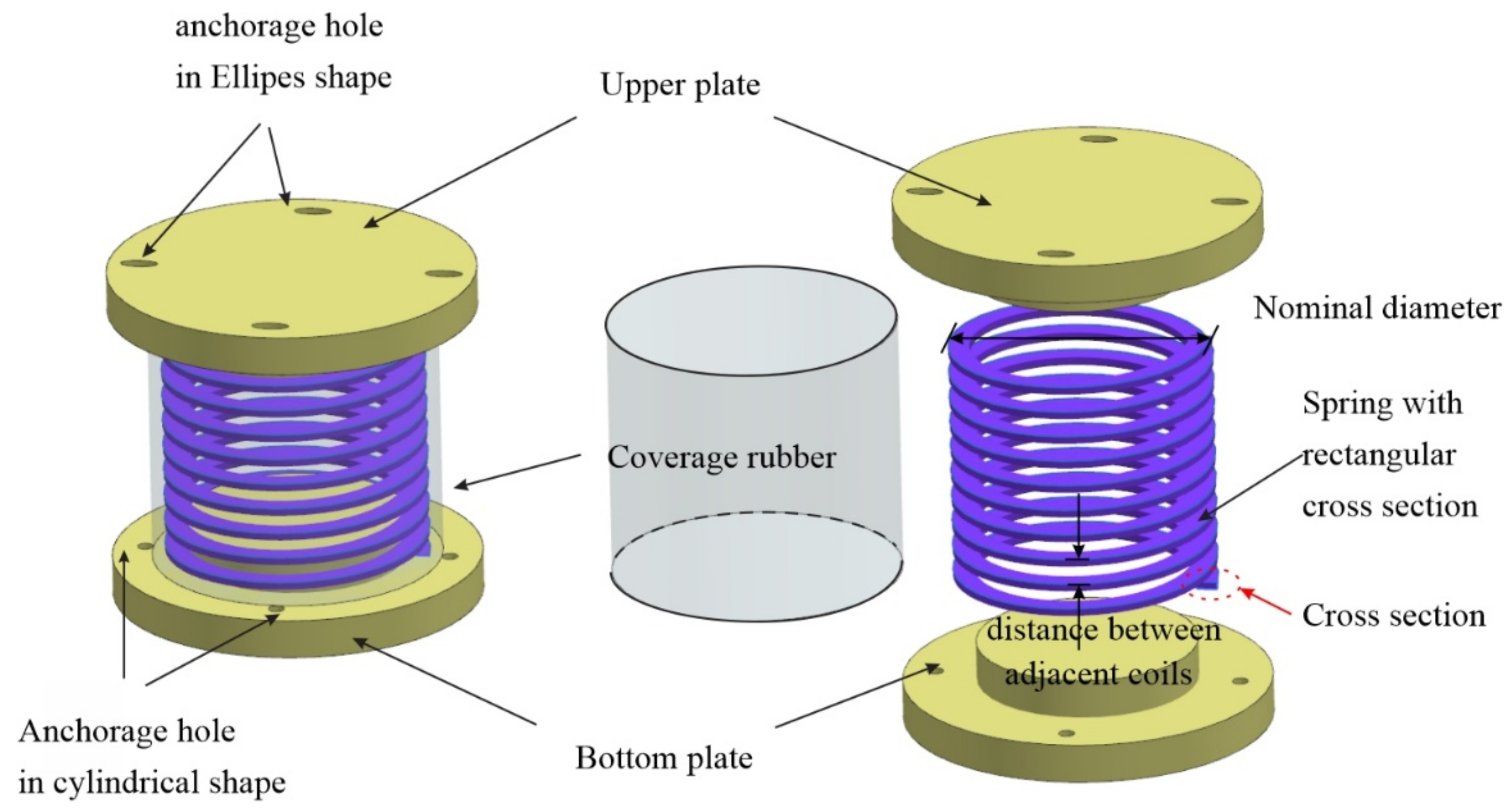
2. Re-Centering Spring Device
2.1. Working Mechanism
2.2. Force–Displacement Relationship
2.2.1. Theoretical Method
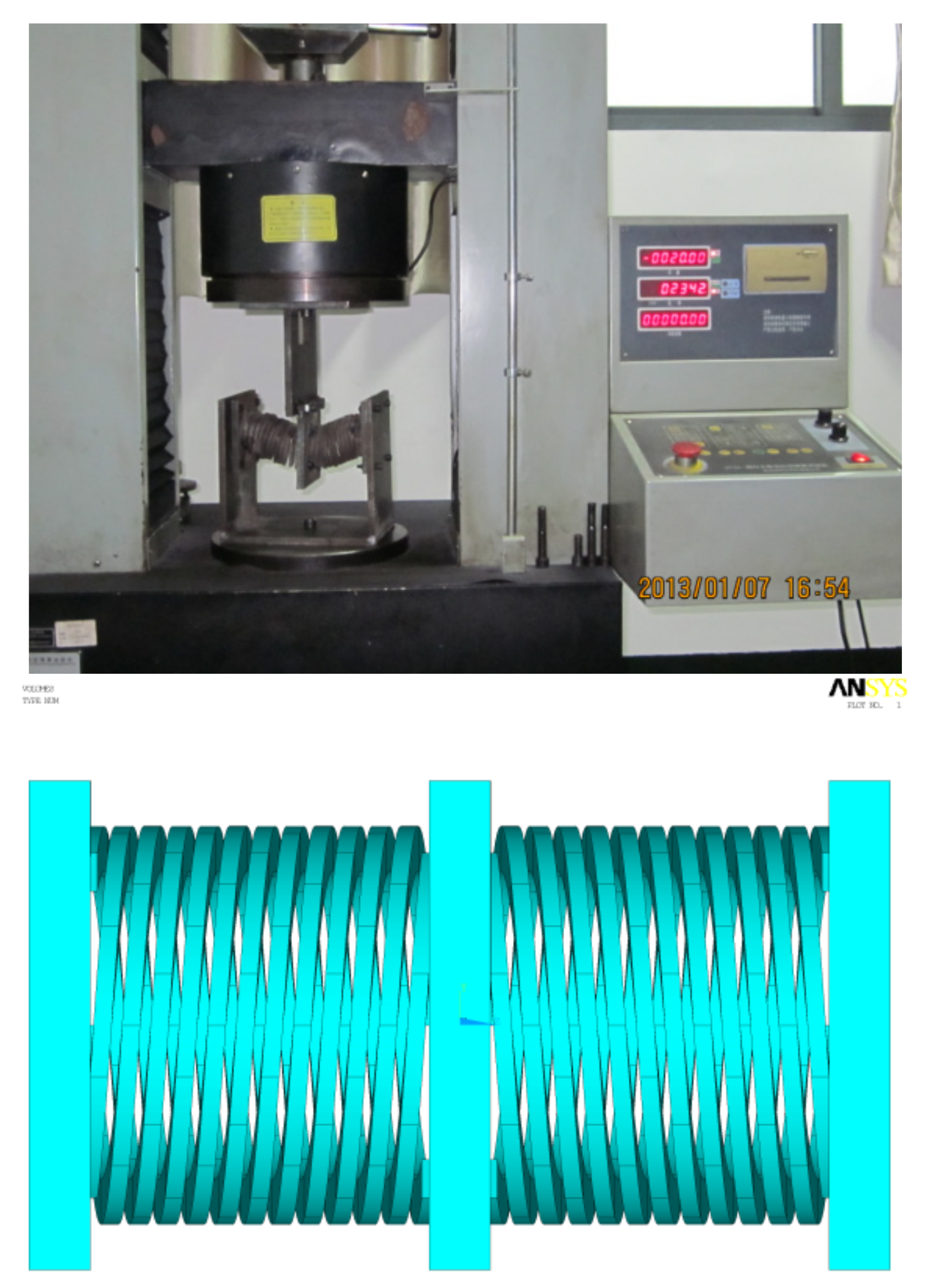
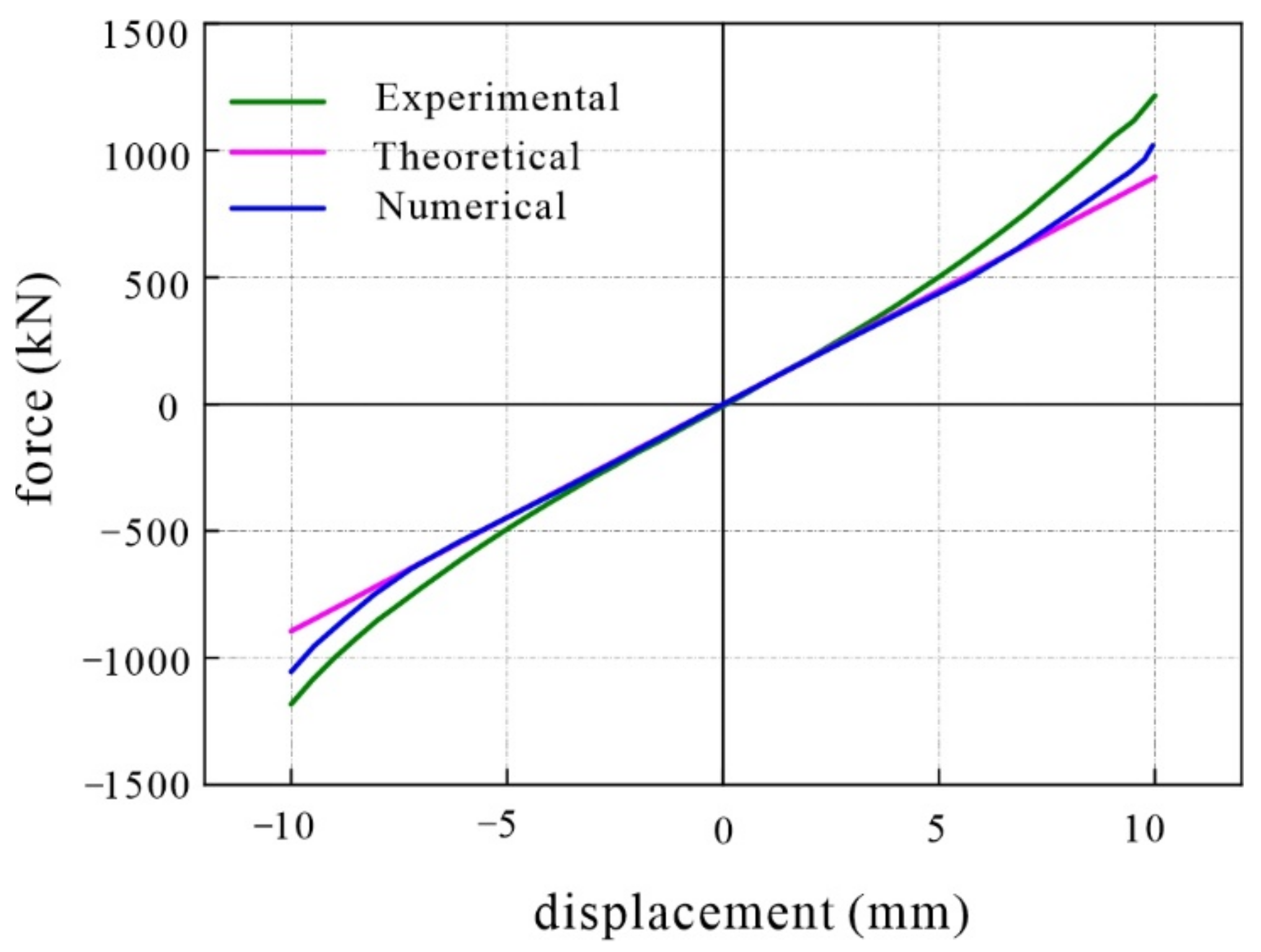
2.2.2. Validation with Experimental and Numerical Data
3. Numerical Illustration
Finite Element Model
4. Analysis Results and Discussion
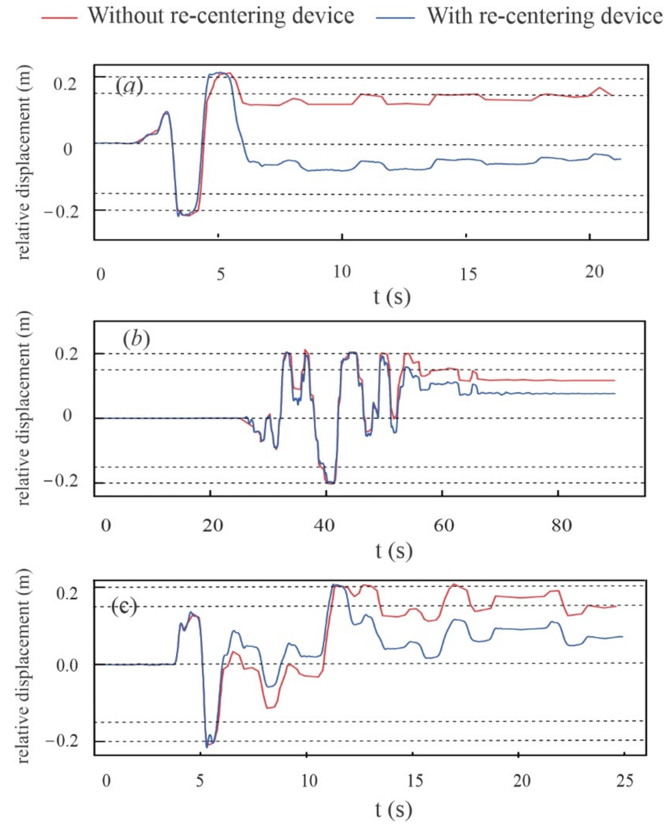
4.1. Displacement and Deformation
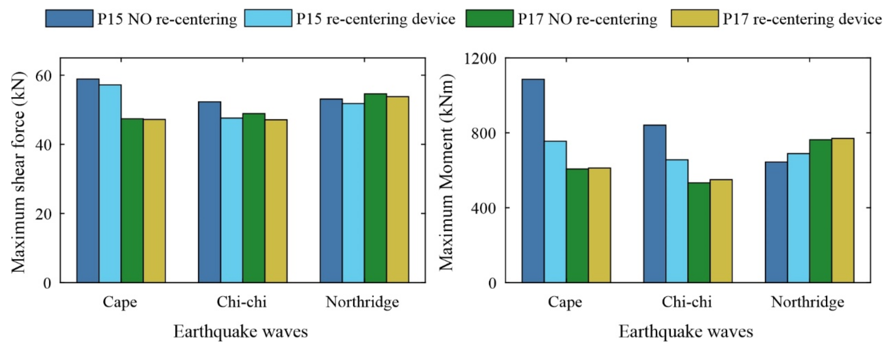
4.2. Shear Force and Moment
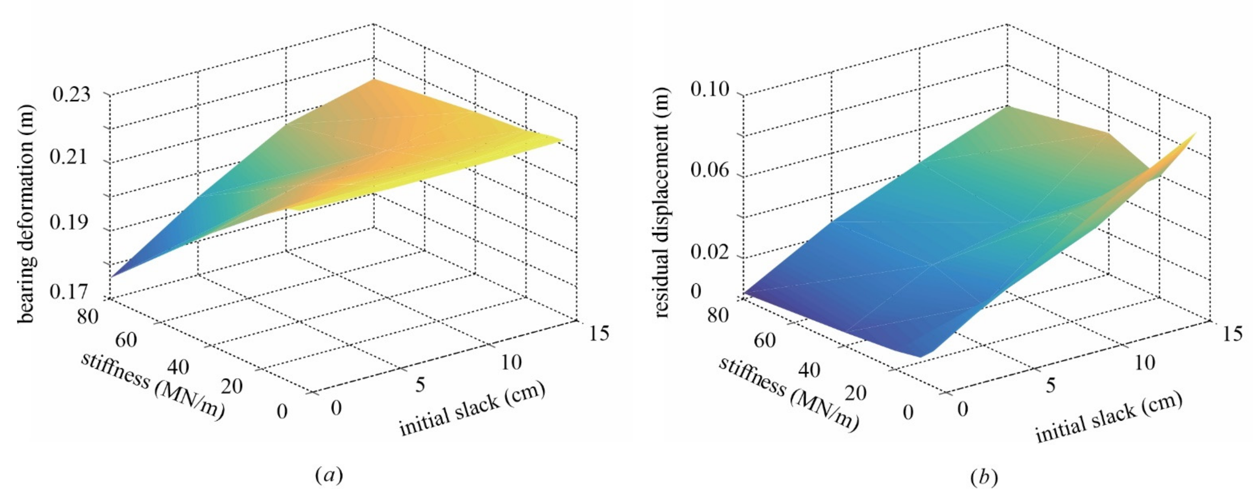
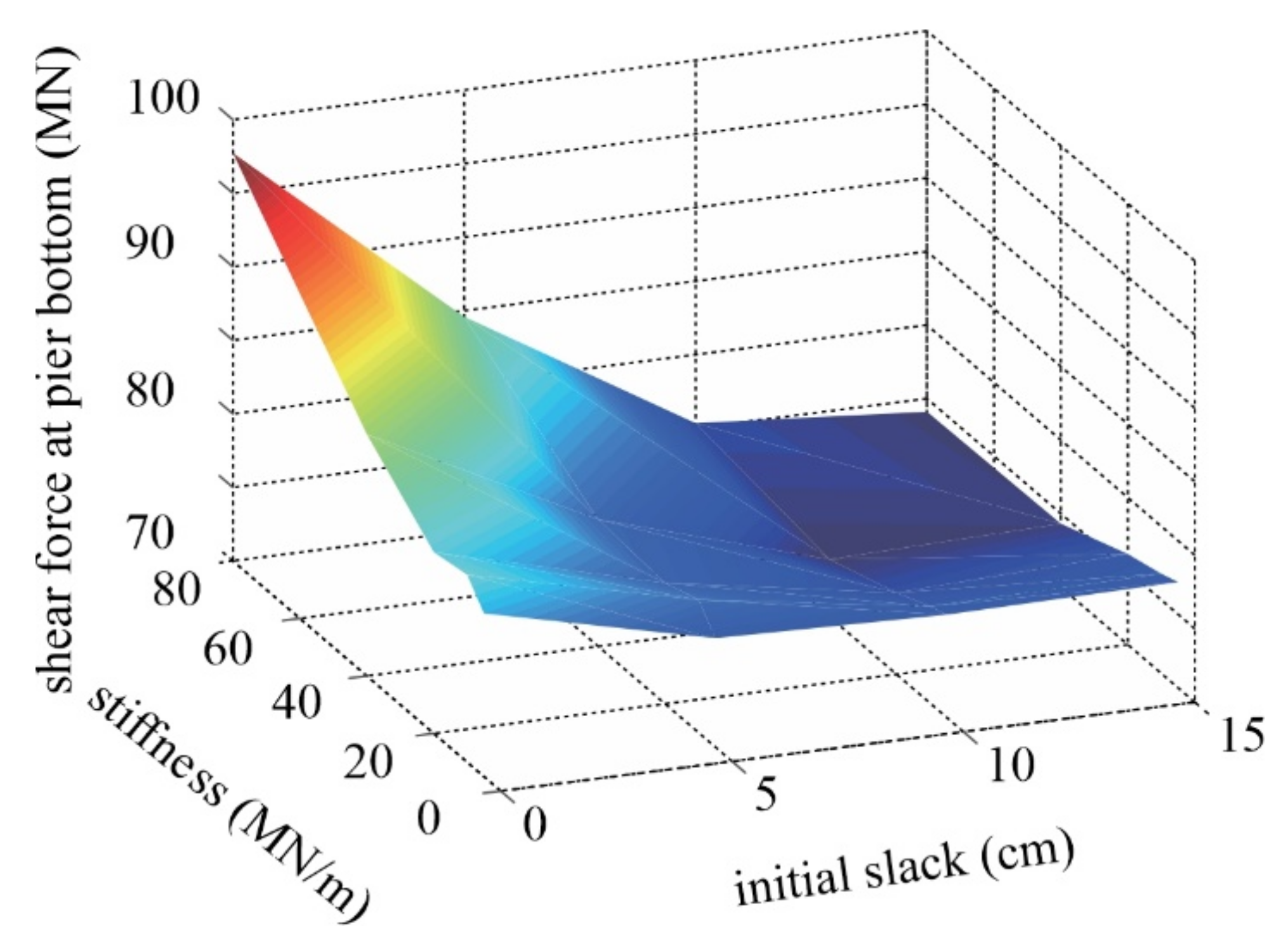
5. Parametric Analysis
6. Conclusions
Author Contributions
Funding
Conflicts of Interest
References
- Chakraborty, S.; Roy, K.; Ray-Chaudhuri, S. Design of re-centering spring for flat sliding base isolation system: Theory and a numerical study. Eng. Struct. 2016, 126, 66–77. [Google Scholar] [CrossRef]
- Pang, Y.; He, W.; Zhong, J. Risk-based design and optimization of shape memory alloy restrained sliding bearings for highway bridges under near-fault ground motions. Eng. Struct. 2021, 241, 112421. [Google Scholar] [CrossRef]
- Cao, S.; Ozbulut, O.E.; Shi, F.; Deng, J. Experimental and numerical investigations on hysteretic response of a multi-level SMA/lead rubber bearing seismic isolation system. Smart Mater. Struct. 2022, 31, 035024. [Google Scholar] [CrossRef]
- Deng, J.; Hu, F.; Ozbulut, O.E.; Wu, S.; Sun, Z.; Cao, S. Verification of multi-level SMA/lead rubber bearing isolation system for seismic protection of bridges. Soil Dyn. Earthq. Eng. 2022, 161, 107380. [Google Scholar] [CrossRef]
- Chen, X.; Xiong, J. Seismic resilient design with base isolation device using friction pendulum bearing and viscous damper. Soil Dyn. Earthq. Eng. 2022, 153, 107073. [Google Scholar] [CrossRef]
- Xiang, N.; Alam, M.S. Comparative seismic fragility assessment of an existing isolated continuous bridge retrofitted with different energy dissipation devices. J. Bridge Eng. 2019, 24, 04019070. [Google Scholar] [CrossRef]
- Xiang, N.; Alam, M.S. Displacement-based seismic design of bridge bents retrofitted with various bracing devices and their seismic fragility assessment under near-fault and far-field ground motions. Soil Dyn. Earthq. Eng. 2019, 119, 75–90. [Google Scholar] [CrossRef]
- Li, S.; Dezfuli, F.H.; Wang, J.; Alam, M.S. Seismic vulnerability and loss assessment of an isolated simply-supported highway bridge retrofitted with optimized superelastic shape memory alloy cable restrainers. Bull. Earthq. Eng. 2020, 18, 3285–3316. [Google Scholar] [CrossRef]
- Cao, S.; Ozbulut, O.E.; Shi, F.; Deng, J. An SMA cable-based negative stiffness seismic isolator: Development, experimental characterization, and numerical modeling. J. Intell. Mater. Syst. Struct. 2022, 33, 1819–1833. [Google Scholar] [CrossRef]
- Chen, X.; Ikago, K.; Guan, Z.; Li, J.; Wang, X. Lead-Rubber-Bearing with Negative Stiffness Springs (LRB-NS) for Base-Isolation Seismic Design of Resilient Bridges: A Theoretical Feasibility Study. Eng. Struct. 2022, 266, 114601. [Google Scholar] [CrossRef]
- Zhou, L.; Wang, X.; Ye, A. Shake table test on transverse steel damper seismic system for long span cable-stayed bridges. Eng. Struct. 2019, 179, 106–119. [Google Scholar] [CrossRef]
- Li, S.; Wang, J.; Alam, M.S. Seismic performance assessment of a multispan continuous isolated highway bridge with superelastic shape memory alloy reinforced piers and restraining devices. Earthq. Eng. Struct. Dyn. 2021, 50, 673–691. [Google Scholar] [CrossRef]
- Yi, J.; Zhou, J.; Ye, X. Seismic control of cable-stayed bridge using negative stiffness device and fluid viscous damper under near-field ground motions. J. Earthq. Eng. 2022, 26, 2642–2659. [Google Scholar] [CrossRef]
- Wei, B.; Hu, Z.; He, X.; Jiang, L. System-based probabilistic evaluation of longitudinal seismic control for a cable-stayed bridge with three super-tall towers. Eng. Struct. 2021, 229, 111586. [Google Scholar] [CrossRef]
- Li, C.; Yang, L.; Li, H. Fragility assessment and optimum design of a steel–concrete frame structure with hybrid energy-dissipated devices under multi-hazards of earthquake and wind. Eng. Struct. 2021, 245, 112878. [Google Scholar] [CrossRef]
- Pang, Y.; Sun, Y.; Zhong, J. Resilience-based performance and design of SMA/sliding bearing isolation system for highway bridges. Bull. Earthq. Eng. 2021, 19, 6187–6211. [Google Scholar] [CrossRef]
- Pang, Y.; Wang, X. Cloud-IDA-MSA conversion of fragility curves for efficient and high-fidelity resilience assessment. J. Struct. Eng. 2021, 147, 04021049. [Google Scholar] [CrossRef]
- Pranesh, M.; Sinha, R. VFPI: An isolation device for aseismic design. Earthq. Eng. Struct. Dyn. 2000, 29, 603–627. [Google Scholar] [CrossRef]
- Hamidi, M.; El Naggar, M.H.; Vafai, A.; Ahmadi, G. Seismic isolation of buildings with sliding concave foundation (SCF). Earthq. Eng. Struct. Dyn. 2003, 32, 15–29. [Google Scholar] [CrossRef]
- Fenz, D.M.; Constantinou, M.C. Spherical sliding isolation bearings with adaptive behavior: Theory. Earthq. Eng. Struct. Dyn. 2008, 37, 163–183. [Google Scholar] [CrossRef]
- Mostaghel, N.; Khodaverdian, M. Dynamics of resilient-friction base isolator (R-FBI). Earthq. Eng. Struct. Dyn. 1987, 15, 379–390. [Google Scholar] [CrossRef]
- Zayas, V.A.; Low, S.A.; Mahin, S.A. The FPS Earthquake Resisting System Experimental Report; Earthquake Engineering Research Center: Oakland, CA, USA, 1987. [Google Scholar]
- Haque, A.B.M.R.; Alam, M.S. Hysteretic Behaviour of a Piston Based Self-centering (PBSC) Bracing System Made of Superelastic SMA Bars–A Feasibility Study. Structures 2017, 12, 102–114. [Google Scholar] [CrossRef]
- Cao, S.; Ozbulut, O.E.; Wu, S.; Sun, Z.; Deng, J. Multi-level SMA/lead rubber bearing isolation system for seismic protection of bridges. Smart Mater. Struct. 2020, 29, 055045. [Google Scholar] [CrossRef]
- Cao, S.; Ozbulut, O.E. Long-stroke shape memory alloy restrainers for seismic protection of bridges. Smart Mater. Struct. 2020, 29, 115005. [Google Scholar] [CrossRef]
- Ozbulut, O.E.; Hurlebaus, S. Re-centering variable friction device for vibration control of structures subjected to near-field earthquakes. Mech. Syst. Signal Process. 2011, 25, 2849–2862. [Google Scholar] [CrossRef]
- Kitayama, S.; Constantinou, M.C. Probabilistic collapse resistance and residual drift assessment of buildings with fluidic self-centering systems. Earthq. Eng. Struct. Dyn. 2016, 45, 1935–1953. [Google Scholar] [CrossRef]
- Kitayama, S.; Constantinou, M.C. Seismic response analysis of single-degree-of-freedom yielding structures with fluidic self-centering systems. Eng. Struct. 2016, 125, 266–279. [Google Scholar] [CrossRef]
- Constantinou, M.C.; Mokha, A.S.; Reinhorn, A.M. Study of sliding bearing and helical-steel-spring isolation system. J. Struct. Eng. 1991, 117, 1257–1275. [Google Scholar] [CrossRef]
- Constantinou, M.; Mokha, A.; Reinhorn, A. Teflon bearings in base isolation II: Modeling. J. Struct. Eng. 1990, 116, 455–474. [Google Scholar] [CrossRef]
- Xu, L.; Fan, X.; Li, Z. Experimental behavior and analysis of self-centering steel brace with pre-pressed disc springs. J. Constr. Steel Res. 2017, 139, 363–373. [Google Scholar] [CrossRef]
- Khoo, H.H.; Clifton, C.; Butterworth, J.; MacRae, G. Experimental study of full-scale self-centering sliding hinge joint connections with friction ring springs. J. Earthq. Eng. 2013, 17, 972–997. [Google Scholar] [CrossRef]
- Wang, S.J.; Yang, Y.H.; Lin, F.R.; Jeng, J.W.; Hwang, J.S. Experimental Study on Seismic Performance of Mechanical/Electrical Equipment with Vibration Isolation Systems. J. Earthq. Eng. 2017, 21, 439–460. [Google Scholar] [CrossRef]
- Guo, W.; Li, J.; Guan, Z.; Chen, X. Pounding performance between a seismic-isolated long-span girder bridge and its approaches. Eng. Struct. 2022, 262, 114397. [Google Scholar] [CrossRef]
- Zhong, J.; Yang, T.; Pang, Y.; Yuan, W. A novel structure-pulse coupled model for quantifying the column ductility demand under pulse-like GMs. J. Earthq. Eng. 2021, 1–19. [Google Scholar] [CrossRef]
- Yang, H.; Pang, Y.; Tian, S.; Dang, X.; Yuan, W. Case study of the seismic response of an extra-dosed cable-stayed bridge with cable-sliding friction aseismic bearing using shake table tests. Struct. Des. Tall Spec. Build. 2017, 26, e1398. [Google Scholar] [CrossRef]
- Yuan, W.; Wang, B.; Cheung, P.; Cao, X.; Rong, Z. Seismic performance of cable-sliding friction bearing system for isolated bridges. Earthq. Eng. Eng. Vib. 2012, 11, 173–183. [Google Scholar] [CrossRef]
- Pang, Y.; Wu, X.; Shen, G.; Yuan, W. Seismic fragility analysis of cable-stayed bridges considering different sources of uncertainties. J. Bridge Eng. 2014, 19, 04013015. [Google Scholar] [CrossRef]
- Li, C.; Li, H.N.; Hao, H.; Bi, K.; Chen, B. Seismic fragility analyses of sea-crossing cable-stayed bridges subjected to multi-support ground motions on offshore sites. Eng. Struct. 2018, 165, 441–456. [Google Scholar] [CrossRef]
- Wei, K.; He, H.; Zhang, J.; Yang, C.; Qin, S. An endurance time method-based fragility analysis framework for cable-stayed bridge systems under scour and earthquake. Ocean Eng. 2021, 232, 109128. [Google Scholar] [CrossRef]
- Pang, Y.; Wei, K.; He, H.; Wang, W. Assessment of lifetime seismic resilience of a long-span cable-stayed bridge exposed to structural corrosion. Soil Dyn. Earthq. Eng. 2022, 157, 107275. [Google Scholar] [CrossRef]
- Zhang, Y.Y.; Ding, Y.; Pang, Y.T. Selection of optimal intensity measures in seismic damage analysis of cable-stayed bridges subjected to far-fault ground motions. J. Earthq. Tsunami 2015, 9, 1550003. [Google Scholar] [CrossRef]
- Li, S.; Zhang, F.; Wang, J.; Alam, M.S.; Zhang, J. Seismic responses of super-span cable-stayed bridges induced by ground motions in different sites relative to fault rupture considering soil-structure interaction. Soil Dyn. Earthq. Eng. 2017, 101, 295–310. [Google Scholar] [CrossRef]
- Zhong, J.; Ni, M.; Hu, H.; Yuan, W.; Yuan, H.; Pang, Y. Uncoupled multivariate power models for estimating performance-based seismic damage states of column curvature ductility. Structures 2022, 36, 752–764. [Google Scholar] [CrossRef]
- Chen, X.; Xiang, N.; Guan, Z.; Li, J. Seismic vulnerability assessment of tall pier bridges under mainshock-aftershock-like earthquake sequences using vector-valued intensity measure. Eng. Struct. 2022, 253, 113732. [Google Scholar] [CrossRef]
- Zhuang, L.; Yin, P.; Pang, Y. E-Cloud: Efficient seismic fragility assessment of structures based on enhanced cloud analysis. Earthq. Spectra 2022, 1–19. [Google Scholar] [CrossRef]
- Pang, Y.; Meng, R.; Li, C.; Li, C. A probabilistic approach for performance-based assessment of highway bridges under post-earthquake induced landslides. Soil Dyn. Earthq. Eng. 2022, 155, 107207. [Google Scholar] [CrossRef]
- Fan, W.; Zhong, Z.; Huang, X.; Sun, W.; Mao, W. Multi-platform simulation of reinforced concrete structures under impact loading. Eng. Struct. 2022, 66, 114523. [Google Scholar] [CrossRef]
- Zhang, N.; Zhang, Y.; Gao, Y.; Pak, R.Y.; Yang, J. Site amplification effects of a radially multi-layered semi-cylindrical canyon on seismic response of an earth and rockfill dam. Soil Dyn. Earthq. Eng. 2019, 116, 145–163. [Google Scholar] [CrossRef]
- Dai, D.; El Naggar, M.H.; Zhang, N.; Wang, Z. Rigorous solution for kinematic response of floating piles subjected to vertical P-wave. Appl. Math. Model. 2022, 106, 114–125. [Google Scholar] [CrossRef]


| Dimension (mm) | Diameter (mm) | Distance between Adjacent Coils (mm) | Number of Coils | Material |
|---|---|---|---|---|
| 2.92 × 7.24 | 57.92 | 14.02 | 24 | 55CrSiA |
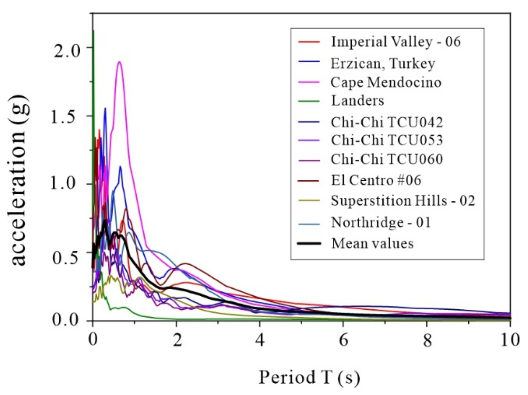
| No. | Seismic Wave | Recording Station | Time | Magnitude | PGA(g) |
|---|---|---|---|---|---|
| 1 | Cape Mendocino | Petrolia | 1992 | 7.0 | 0.662 |
| 2 | Chi-chi, Taiwan | TCU053 | 1999 | 7.6 | 0.223 |
| 3 | Northridge-01 | Newhall-W pico canyon rd | 1994 | 6.7 | 0.325 |
| No. | Without | With |
|---|---|---|
| 1 | 0.302 | 0.266 |
| 2 | 0.276 | 0.259 |
| 3 | 0.242 | 0.26 |
Publisher’s Note: MDPI stays neutral with regard to jurisdictional claims in published maps and institutional affiliations. |
© 2022 by the authors. Licensee MDPI, Basel, Switzerland. This article is an open access article distributed under the terms and conditions of the Creative Commons Attribution (CC BY) license (https://creativecommons.org/licenses/by/4.0/).
Share and Cite
Yin, P.; Wang, J.; Pang, Y. Seismic Performance of a Sliding Isolation Bridge System with a New Spring Re-Centering Device. Sustainability 2022, 14, 10720. https://doi.org/10.3390/su141710720
Yin P, Wang J, Pang Y. Seismic Performance of a Sliding Isolation Bridge System with a New Spring Re-Centering Device. Sustainability. 2022; 14(17):10720. https://doi.org/10.3390/su141710720
Chicago/Turabian StyleYin, Pengcheng, Jianguo Wang, and Yutao Pang. 2022. "Seismic Performance of a Sliding Isolation Bridge System with a New Spring Re-Centering Device" Sustainability 14, no. 17: 10720. https://doi.org/10.3390/su141710720
APA StyleYin, P., Wang, J., & Pang, Y. (2022). Seismic Performance of a Sliding Isolation Bridge System with a New Spring Re-Centering Device. Sustainability, 14(17), 10720. https://doi.org/10.3390/su141710720