1. Introduction
The Zigbee Alliance was founded in the year 2002. Its main task is to improve or provide a foundation for both public and private industries that work with wireless technologies to build effective and efficient wireless sensors and control systems that require less energy, can operate at low data rates, and have low manufacturing and maintenance costs.
Since its introduction in 2006 [
1], the Zigbee specification has risen to prominence. It will eclipse the global control/sensor network standard and rule residential, medical, industrial, and commercial applications. Zigbee provides two-way communications for command and control, has a 75–100 m range, and control sensors that help us accomplish various tasks. Residential applications include lighting control units, smoke or CO
2 detectors, fire detectors, HVAC control, security, wireless transmission for television set-top boxes, and remote control. Zigbee is now also integrated into cell phones, allowing you to use your phone as a remote device, such as a remote for televisions and air conditioners.
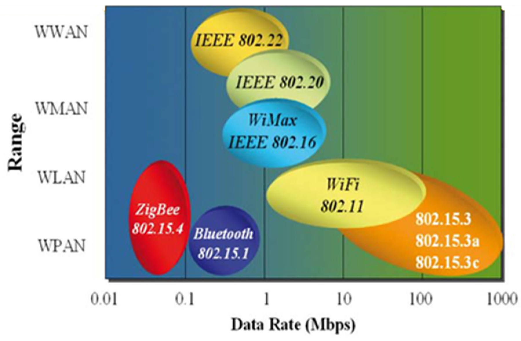
Regarding industry, there are numerous areas where Zigbee has begun to play a prominent role, such as monitoring, automation, medicine, etc. The main secret to Zigbee’s success is its adaptability, which allows it to fit into any task. Although the data rate of Zigbee is significantly lower than that of Wi-Fi, it does not necessitate any higher rate or clarity in data transmission. For example, a low data rate is sufficient if we are talking about an intrusion sensor. As we all know, a low data rate consumes less power, making our device more energy efficient. Compared to other technologies, Zigbee technology’s energy efficiency allows it to gain a firm foothold in the industry as shown in
Figure 1.
1.1. Zigbee Device Types
Zigbee devices are of three types:
- (1)
Zigbee coordinator (ZC): A coordinator is required both in the real world and the computer world. The coordinator is the most capable and efficient device, acting as the root of the entire network structure and bridging the gap between other networks. For effective operation, each network should or must have one coordinator. The coordinator’s primary responsibility is to store information about the network’s nodes while also acting as the commander who ensures the system’s security and integrity.
- (2)
Zigbee Router (Z.R.): The network also requires gateways or intermediate nodes for message routing or path formation; this task is performed by Zigbee routers, which form the entire network under the supervision of the coordinator.
- (3)
Zigbee End Device (ZED): We have the coordinator and the network, but we still need a device that communicates with the natural or physical world. The ZEDS are devices that communicate with the physical world. They remain inactive or in sleep mode until an unknown factor activates them, saving a significant amount of electricity.
1.2. Operating Modes and Low Power Consumption
Zigbee technology has two main communication modes that support various types of two-way data traffic: non-beacon mode [
2] and beacon mode. The first mode is the beacon mode, designed for battery-powered coordinators or coordinators with no continuous power supply, saving most energy. In contrast, the second mode, the non-beacon mode, is designed for coordinators with a continuous power supply.
In beacon-mode networks, the coordinator device periodically wakes up or becomes active and sends beacons or signal messages to the routers or intermediate nodes in its network. This message signal alerts other devices or nodes to check the network for any messages, information signals, or inbound data. If there is no incoming information or message, the coordinator and the intermediate nodes return to the inactive mode, or in layman’s terms, they fall asleep. We can now clearly see that a beacon-oriented network operates in time slots or periods—that is, nodes are active only when there is an information or a beacon in the network [
3]. As a result, the nodes in such a network have longer battery lives and shorter life cycles because they are active only when there is a message or information signal in the network; otherwise, they are inactive and use less electrical power.
In nonbeacon mode, the operation is quite different; some devices are always active, while others switch roles. Because they expect data from other devices, nodes such as the coordinator and routers do not sleep and must remain active at all times. This mode requires an average power supply, which is still more than the beacon mode, but its overall power consumption is low because most network devices or nodes can remain inactive or sleep for long periods. In short, Zigbee devices’ power is deficient compared to other technologies such as Bluetooth and Wi-Fi. The reason for this is the operation mode of Zigbee devices, which allows them to remain active or inactive depending on the area where they have been implemented.
Switching between modes provides Zigbee with a practical feature for saving significant electrical energy, propelling it to the forefront of wireless technology. Since its introduction in 2006, the Zigbee specification has risen to prominence. It will eclipse the global control/sensor network standard and rule residential, medical, industrial, and commercial applications [
4]. Zigbee provides two-way communications for command and control, has a 75–100 m range, and control sensors that help us accomplish various tasks. Residential applications include lighting control units, smoke or CO
2 detectors, fire detectors, HVAC control, security, wireless transmission for television set-top boxes, and remote control. Networking is used in almost every field of automation and computerization. We are all familiar with standard networking techniques; we all understand what an I.P. address means when we talk about computers; we are all familiar with OSI layers and the functionality of each layer.
Networks enable us to connect different machines and share their resources, improving resource sharing and making computation easy and cheap. We must also consider device networking to achieve automation when we talk about automation. However, networking becomes quite difficult when discussing low-power microcontrollers [
5], i.e., 8-bits/16-bits. The main goal of the research is to build a network of devices with low-power microcontrollers, such as various home appliances, and to communicate voice over it wirelessly to provide a means for automation [
6,
7].
1.3. Zigbee Work Principle
The Zigbee and 802.15.4 standards provide us with two types of devices. The first is complete function devices (FFDs), and the second is reduced function devices (RFDs) (RFDs). Both devices have 64-bit IEEE addresses [
8], but they can also be assigned short 16-bit addresses to reduce packet size. The FFDs can be implemented as network coordinators that coordinate and manage the entire network, or they can be implemented as routers, while the RFDs are devices that interact with the real world. A coordinator is required in all networks and has information about the notes in its network. The coordinator configures and maintains the network, stores information, and checks security. Routers serve as intermediate gateways, providing channels or passages for data to flow from one device to another. They have less functionality than the coordinator, which reduces manufacturing complexity and costs, and they require a limited amount of energy and memory.
1.4. Motivation
ZigBee’s low power consumption may be attributed to its slow transmission rate and sleep mechanism. A ZigBee device can function for six months when powered by two batteries. The Zigbee protocol has a short time latency. The average time delay for a searching device is 30 ms, the waking time is 15 ms, and the channel access time is 15 ms. ZigBee has a high net capacity and is organized in a star formation. ZigBee networks can accommodate up to 254 end devices, although any region can only have a maximum of 100 ZigBee networks. ZigBee is known for its dependability. The CSMA-CA protocol is used for channel access by MAC. Every packet requires a confirmation message from the node that is receiving it; if a packet is lost, the node that is sending it will send it again. ZigBee offers a high level of protection by doing an integrity check on each packet using a Cyclic Redundancy Check (CRC) and an AES symmetric key.
Bluetooth and Wi-Fi need much more power than other wireless networking standards and cannot be incorporated into compact devices. This is one of the typical benefits of using a ZigBee phone.
1.5. Organization of Paper
The following is how this paper is structured.
Section 2 describes the current state of the art.
Section 3 describes the materials and methods used in the Zigbee technology deployment.
Section 3 describes the statistical analysis performed on the data obtained during network deployment.
Section 4 displays the final result of the Zigbee channel modeling. Finally, in
Section 5, the results of related works, as well as the conclusions of this research and future works to be developed, are discussed.
2. Literature Review
There is a wealth of information available on wireless communications. There are also journals on various wireless communications topics. The articles in this issue were chosen to demonstrate new approaches in toll rate determination techniques as well as reports on industrial applications of some techniques.
On the other hand [
9], the propagation analysis is performed within an anechoic chamber at a maximum distance of 4 m, presenting a valid model under ideal conditions without interference, making a model limited and not very applicable in reality; the model presented in this research was characterized from data obtained in the field under real conditions, allowing it to be used in applications for networks that meet the previously mentioned characteristics and descriptors.
While [
10] obtained a propagation model for Zigbee communication over long distances through simulation, the resulting model has a high error, around 10%, due to the wide intervals (up to hundreds of meters) between data collection points, the model obtained in the current investigation has a mean square error of approximately 3%.
Finally, Ref. [
11] obtained a model of the Zigbee propagation channel at 2.4 GHz in outdoor environments with a logarithmic adjustment for distances up to 200 m, where a discontinuity is found at 60 m. While the Zigbee propagation channel is modeled at 2.4 GHz in outdoor environments, analyzing the effect of the discontinuity due to device height, which describes a decreasing exponential curve as the height increases, the discontinuity approaches the device that transmits the signal until it reaches its asymptote at 60 m, a point at which the said discontinuity tends to stabilize, it is justifiable that at a higher elevation the discontinuity tends to stabilize. The model presented in this work divides the propagation into two segments for analysis, with the decisive point being the point where the discontinuity is generated. This point is taken into account in the current investigation, which generates a mathematical equation to locate it and, from there, calculate the losses of the link at a certain distance at a specified height.
We are interested in continuing this line of research to investigate the causes of the gap in wave propagation, which is referred to as a point of discontinuity in this work [
12]. On the other hand, it is intended to develop tests on a broader range of scenarios, deepening the effect of obstacles and the influence of the line of sight, to broaden the scope of the model presented and provide the scientific community with a more general propagation model.
The propagation analysis in [
13] is carried out within an anechoic chamber at a maximum distance of 4 m, presenting a valid model under ideal conditions without interference, making it a model limited and not very applicable in reality; the model presented in this research was characterized from data obtained in the field under real conditions, allowing it to be used in applications for networks that meet the previously mentioned characteristic.
While Ref. [
14] obtained a propagation model for Zigbee communication over long distances through simulation, the resulting model has a high error, around 10%, due to the wide intervals (up to hundreds of meters) between data collection points, the model obtained in the current investigation has a mean square error of approximately 3%.
Finally, Ref. [
15] obtained a model of the Zigbee propagation channel at 2.4 GHz in outdoor environments with a logarithmic adjustment for distances up to 200 m, where a discontinuity is found at 60 m. While the Zigbee propagation channel is modeled at 2.4 GHz in outdoor environments, analyzing the effect of the discontinuity due to device height, which describes a decreasing exponential curve as the height increases, the discontinuity approaches the device that transmits the signal until it reaches its asymptote at 60 m, a point at which the said discontinuity tends to stabilize, it is justifiable that at a higher elevation the discontinuity tends to stabilize. The model presented in this work divides the propagation into two segments for analysis, with the decisive point being the point where the discontinuity is generated. This point is taken into account in the current investigation, which generates a mathematical equation to locate it and, from there, calculates the loss of the link at a certain distance at a specified height.
Chen Chen et al. [
16] proposed the traffic meters overhead scheduling in the uplink and downlink on the Internet of energy can be mitigated to a greater extent using the power saving scheduling scheme in this paper. The replacement of the battery in the S.G. network is not an easy process. Therefore, the proposed method is suitable for almost all applications. Considering the proposed model’s extraordinary character and service model, the STAs battery life of the network can also be extended (Chen et al. [
16]). They also proposed a scheme for the allocation of AID dynamically, in which, based on the duration of the average service, the AIDs of STAs are assigned. The characteristics of AIDs are used to occupy as they are similar to those of scheduled STAs. All these functions are performed to make the model more efficient and effective. With the help of the proposed compressed bitmap scheme, the communication overheads are reduced to a greater extent. This scheme is introduced in the Power Saving polling scheme for S.G. on the Internet of Energy (PSSG). The analysis concludes that the proposed approach’s performance is better than previously existing techniques concerning specific performance parameters.
Mian Muhammad Ahmed et al. [
17] presented in the Information and Communication Technology (ICT) the massive advancement of the Internet of Things (IoT) as it emerged as a fast-growing technology. In the upcoming years, more than 50 billion devices will become part of the IoT as it has vast applications. The IoT network’s foremost priority is the devices’ security (Ahemd, Shah & Wahid, [
18]). They evaluated the security challenges faced by the IoT architecture in the four layers and proposed solutions to tackle those issues. They also analyzed the essential security technologies like encryption in the IoT and discussed the countermeasures of security attacks on different layers of IoT.
Jyoti Deogirikar et al. [
19] presented the widely known topics utilized in the research area and almost every application known as the Internet of Things (IoT). It is the future of technology, according to many researchers. In the field of IoT, significant research and development have occurred as it provides virtual assistance for many applications. Still, there are some vulnerabilities in this field. These vulnerabilities lead the technology of IoT in danger. Various kinds of attacks on the IoT were invented so far before its actual commercial implementation of it (Deogirikar & Vidhate, [
19]). In this paper, various IoT attacks were discussed and classified to tackle these attacks in IoT. They presented a survey on the various attacks and compared their efficiency.
Xiaosen Liu et al. [
20] discussed using a monolithic microwatt-level charge, which pumps the extra required energy within IoT systems to provide an energy harvester for intelligent nodes. The charge pump was optimized within the proposed architecture and circuit level research due to the differences in the accessible voltage and power. The hybrid conversion ratios are provided to reduce the charge redistribution loss within a reconfigurable charge pump in the initial stage (Liu et al., [
20]). With the help of frequency modulation, the reconfigurable feature is turned into maximum power point tracking (MPPT). This results in generating a 2D MPPT system. As a sensing approach, the MPPT method is used along with the constant-on-time (COT) scheme, which is a regulation part. This helps in removing the method that provides energy within the latest technologies. The energy sources are harvested with the help of a proposed method that includes many intelligent nodes in it as well. It is considered per the simulation results that the proposed method resulted in providing a simple and enhanced PCE method that provides very high power.
Using the Internet of Things (IoT), Mukrimah Nawir et al. [
21] demonstrated a complex network of intelligent devices that exchange data. There is a location-based approach that uses wireless systems to handle the soft mobile-controlled vertical handover, as proposed by Inzerilli et al. [
22]. The UMTS and IEEE 802.11 network interface cards of the du-al-model terminal are examined in detail. This novel approach optimizes the well put and controls the ping-pong effect. The preliminary handover initiation phase is started based on the location of the mobile node. Casting a transient during soft handover and then performing handover provides a good put estimation phase. Location information is used to make handover decisions based on experimental results.
Recursive Principal Component Analysis (R-PCA) was used in a cluster-based data analysis framework proposed by T. Yu et al. [
23]. As a result, the aforementioned problems are reduced as a result of this approach. The principal components (P.C.s) of a network combine all of the data gathered by a cluster member within the cluster head, which is where the network’s data is stored. Data outliers were identified using the Squared Prediction Error (SPE) score, also known as the square of residual values, following the extraction of P. Cs (also known as squared residual values). The PCA model’s parameters have been updated by the IoT using R-PCA.
According to R. Lu and co-authors, Ref. [
24] many techniques are used to describe the proposed method in the network. As a result, it is simple to discover false data using this approach. A series of experiments were conducted to demonstrate the effectiveness of the proposed method in the context of fog computing-enhanced IoT.
L. Dong et al. [
25] suggested that an Improved-Network Aggregation and Distribution of conditional IoT Subscription solution (INADS) be used for Information-Centric Networking (ICN). As a result, future implementations should use this method instead of others. In both single- and multiple-producer scenarios, the number of notifications can be reduced using this method. This method has the advantage of reducing power consumption.
Exiting Model
The existing system used a laying sensor to detect a vehicle’s axle in the lane leading to the toll booth when the vehicle possessed through the sensor. After sensing, the vehicle generates a signal, and the processing device processes the signal to determine the exact number. The electronic toll collection system overlaps with the microcontroller, and the electronic toll collection system collects the toll based on the vehicle’s weight.
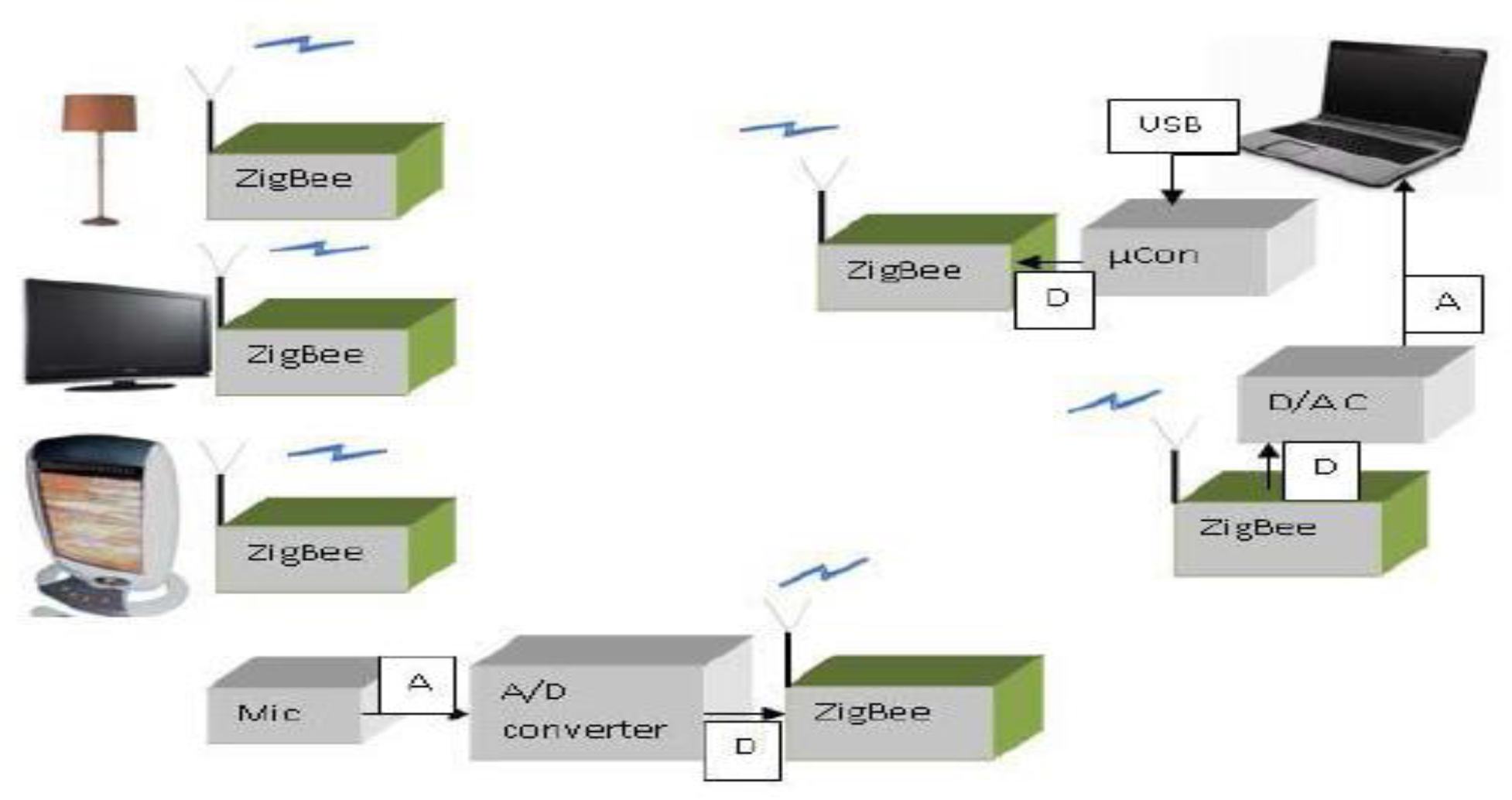
Figure 2 represents the architecture of the VoSN System. It represents the standard architecture of the VoSN System, which is currently used to transmit data in different applications like toll plazas and number plate reorganization systems [
26].
The ZigBee module primarily instructs this module to obtain the state of the relay and then to manage the output power of the outlet, which it does via receiving control instructions. The transistor amplifies the ZigBee module’s controller signal, which is then sent to the driving relay for further processing. A reverse voltage is generated by the free-wheeling diodes on each side of the relay, rapidly switching the relay from ON to OFF, protecting the transistor [
27].
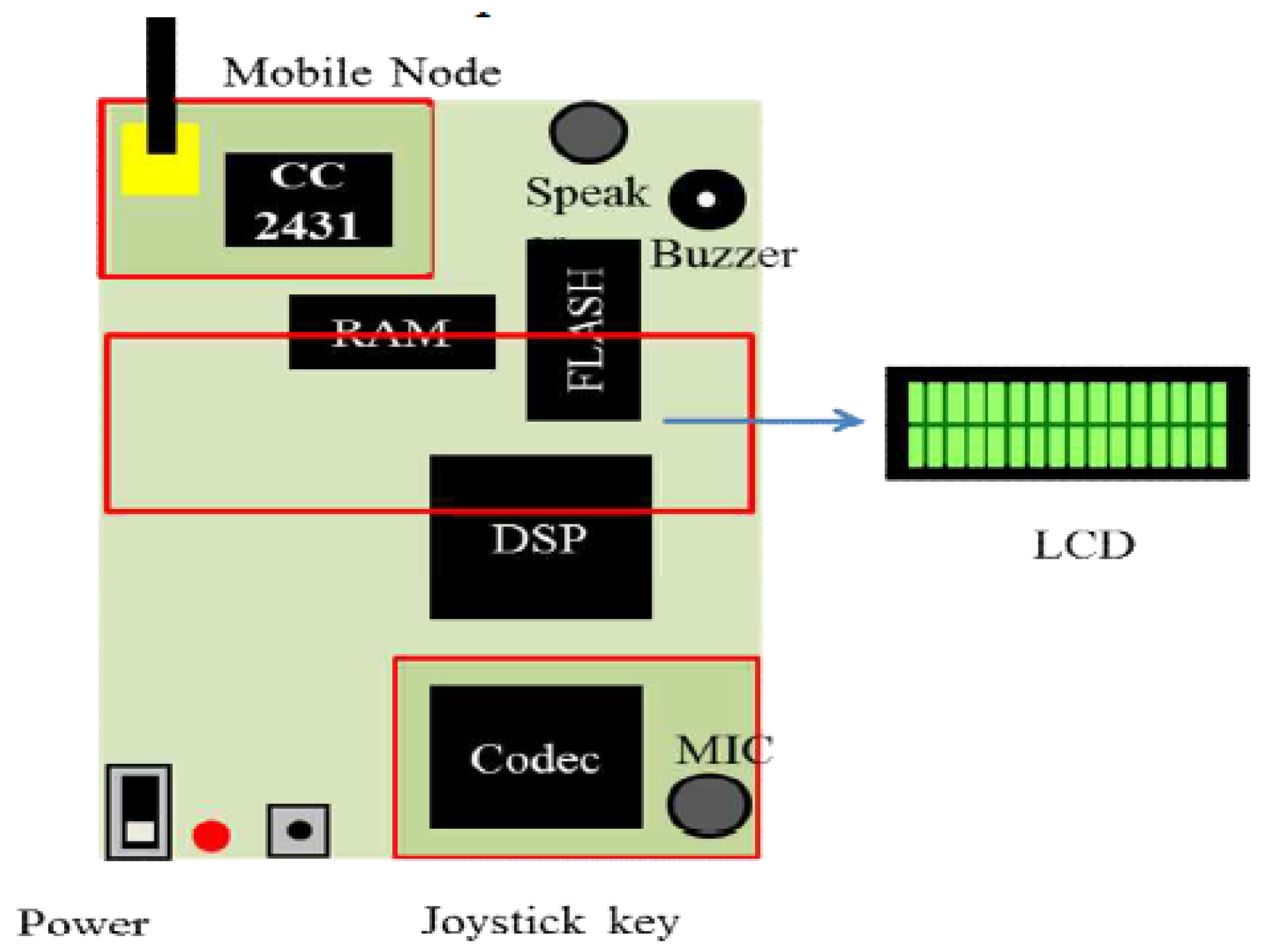
Figure 3 represents the application of the Zigbee module in which Mobile Node consists of the following parts: Voice Codec, DSP, CC2431, battery, speaker, buzzer, MIC, flash RAM [
28,
29], etc. The M.N. structure and components are shown in
Figure 4.
3. Proposed Methodology
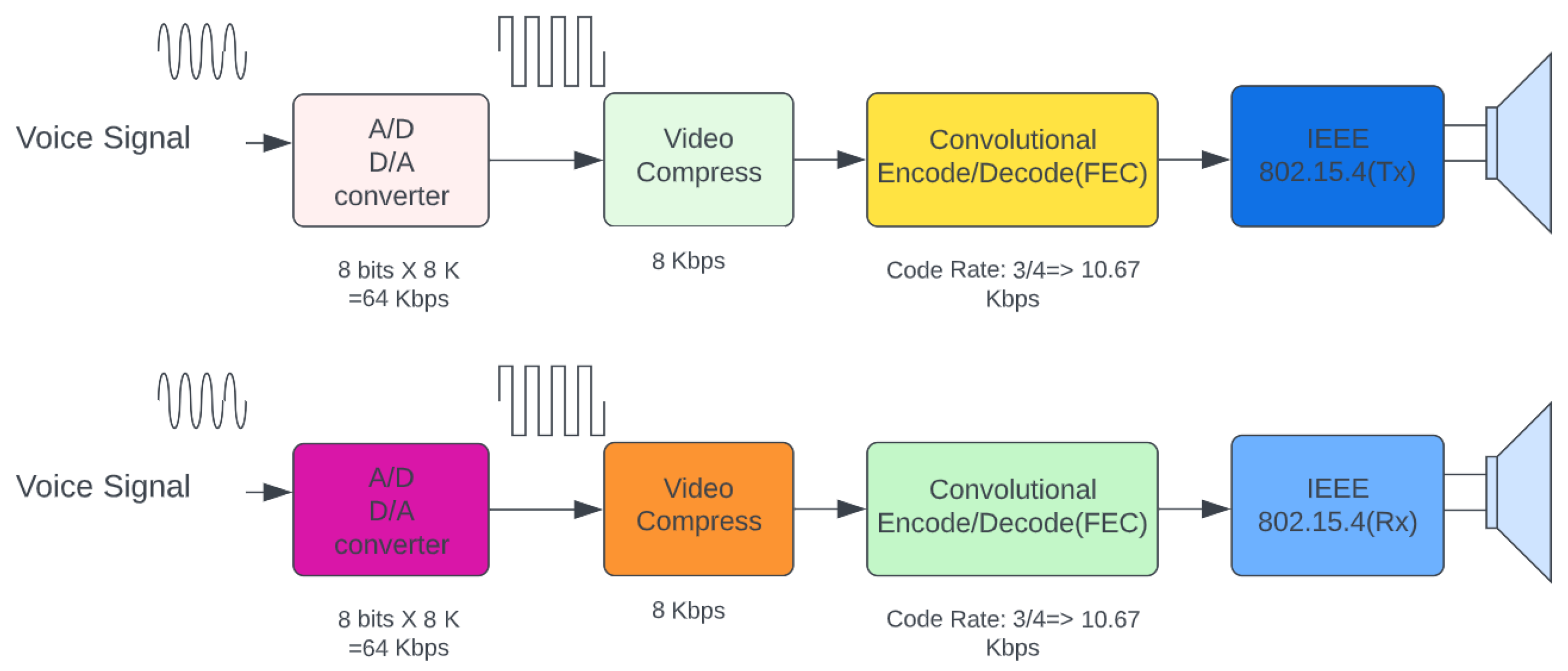
The proposed work is divided into two separate segments. The first module converts the signal from analog to digital, while the second module applies the DSP approach to further process the signal.
The transmitted signals of vice wave data are as follows:
The received signal of the voice wave is as follows:
where:
—delay time.
The distance between the receiver and the sender is as follows:
The relation between distance and delay time is as follows:
Its in this section that we evaluate the root-mean-square current rms as well as the total voltage harmonic distortion the total current harmonic distortion and the overall power factor P.F.
An ADC [
30] transforms an analog signal into a digital signal in analog-to-digital conversion. The measurement I.C. uses a second-order sigma-delta ADC with a 22-bit resolution to translate voltage and current signals. Using a finite impulse response (FIR) filter, the ADC’s output is reduced and stored in the C.E.’s random-access memory (RAM). The measuring I.C. can accept a maximum signal of
. To convert
to D.C.
, a high-resistance voltage divider with an appropriately designed resistance is employed. It is also possible to convert
into
by using a current converter to measure the current signal with the necessary resistance.
There must be a precise number of data points for the fast Fourier transform (FFT), which is efficient but has a tight requirement for the number of recorded data points. The lowering the spectrum leakage problem or the hurdle effect will likely happen if we utilize the FFT to process data, which does not meet our objectives. Because the DFT technique requires just 100 data samples/points throughout a period and has an adequate temporal range, we utilize it instead of the FFT in this system [
31].
Data from a voltage or current signal predicts how it will behave in the future. It can be shown that x(n) has a DFT, which is
, which is defined as the frequency-domain sequence of complex values of
in the form of
. For frequencies
and k, the decimation-in-time FFT technique computes the DFT values as follows:
Both the real and fictitious components are represented in this way. Calculation of the reactive power Q and the active power
P may be done as follows:
S and PF by using the following formulas:
and
are the total voltage and current harmonic distortions calculated as follows:
3.1. Hardware Description of Transmitter
A.C. to D.C. converters are bridge rectifiers because they correct the mains A.C. input. Bridge rectifiers are a typical component in power supplies that offer D.C. voltage to many electronic components and devices. A 220 V A.C. supply is used as an input for the system or prototype. A step-down transformer is used to reduce the high supply voltage to 12 V A.C. for safe use. After that, the bridge rectifier produces a fully rectified A.C. signal from the 12 V supply [
32]. As a result, an unregulated 12 V D.C. is outputted from the main capacitor. The circuit also includes a filter capacitor to eliminate noise.
To determine the discrepancy between the real-time and the time stamp (ticks) of the vice, signals are computed as
We assume to computed
as for voice data
The final expression is computed as
The two primary modalities of ZigBee data transfer depicted in
Figure 5 are non-Beacon mode and beacon mode. The beacon mode, the first mode in which coordinators and routers monitor changes in data flow, consumes a significant amount of power. A node may receive and respond to any signal at any time. As a result, routers and coordinators are unable to sleep in this mode. Although it requires more electricity, the overall power consumption is low because the majority of the system’s devices are dormant for extended periods of time. After that, the signal is routed to two I. Cs, LD33 and 7805. The LD33 outputs 3.3 V D.C. to the Zigbee, whereas the IC7805 [
33] produces 5 V D.C. to the microphone. The microphone used for voice input is a condenser mic, and its primary function is to convert an audio signal into an electrical signal. The mic’s output is centered on the 5 V DC supply.
3.2. Hardware Description of Receiver
The transmission segment, a 220 V A.C. supply, is used as an input to the reception side of the system or prototype. Due to the high supply voltage, a step-down transformer is used to reduce it to 12V A.C. The 12 V supply is converted to a fully rectified A.C. signal using a bridge rectifier [
34]. The primary filter capacitor’s output is then passed on, resulting in an unregulated D.C. voltage of 12 volts. The circuit additionally includes a noise-eliminating filter capacitor. Three I.C.s (LD33, 7805, and 7809) received 12 V D.C. Three chip capacitors are available. The LD33 IC generates 3.3 volts of direct current, the 7805 IC generates 5 volts of direct current, and the 7809 IC generates 9 volts of direct current.
Zigbee demodulates the signal once it is received. The Zigbee signal can be between zero and three volts.
Table 1 illustrates the Zigbee protocol idea.
Zigbee receives the signal and then demodulates it. The Zigbee signal can be between 0 V and 3.3 V. The concept of the Zigbee protocol is shown in
Table 1.
Simply put, chip capacitors are just capacitors that have been built as integrated circuit (I.C.) devices, which are sometimes referred to as chips or microchips. The microcontroller cannot operate on a 3.3 V data signal; hence the signal needs to be amplified [
35,
36]. This is achieved by using IC MAX 232. In
Figure 6, most ground wires will be green or primarily green. That is why the different colors represent it; the pin description of IC MAX232 implemented in this section is shown in
Table 2.
The output produced by MAX 232 is a digital signal. This signal’s amplitude alters between 0 Volts and 5 Volts [
37]. This signal is then fed as an input to the microcontroller. The pins of the microcontroller are described in
Table 3.
Second amplifier produces a louder voice signal and feeds this into speaker via the output of first amplifier and second amplifier.
Fast Fourier transform (FFT) is adequate, but it has a strict data acquisition specification. This rule states that the number of data points collected must exactly equal the power of two [
38]. Let’s take a look at the numbers with the Fourier transform (FFT). When it comes to minimizing spectrum leakage or the hurdle effect, we could cause issues that are inconvenient to our goals. DFT is used to analyze data instead of FFT because it only requires 100 data samples/point per period and has a suitable temporal range [
39].
Let’s say that we have an x(t) voltage or current signal, which is sampled at regular intervals of time T, and that the sampling sequence is x(n). x(n) is denoted as the number of times the signal is sampled. In the frequency domain, the series of complex values in the form
is defined as the discrete Fourier transform (DFT) of
, where
w0 is the fundamental frequency and is determined by the formula
. It is stated in [
40] that the decimation-in-time FFT technique recommends that the DFT values for the frequency
should be computed in this manner.
where
is the twiddle factor; given the DFT values
and
, the root-mean-square values
and
of the sampled voltage, and the current values
and
can be computed as follows:
where
and
represent, respectively, the real and fantastical elements of the whole. The following is a calculation that may be used to determine both the active power
P and the reactive power Q:
Finally, the total voltage harmonic distortion
and the total current harmonic distortion are computed as follows: the total voltage harmonic distortion (abbreviated as
and the total current harmonic distortion (abbreviated as
may be calculated as follows:
4. Results and Discussions
The prototype of this system has been fabricated and tested, as shown in
Figure 7 and
Figure 8. The models have been constructed using off-the-shelf components that drastically reduce costs [
41].
The probability that node m “broadcasted from node “
I” selects the node “
j” in the optimal set of solutions is given as
where:
α and β are constants and define the weights assigned to pheromone and heuristic such that .
µ represents the weight for each ant’ m.
Area(i) indicates the communication range of the node’s i
In Proposed approach, two heuristics have been correlated with two different objective functions. Nodes’ energy information informs the first heuristic, whereas the nodes’ PDRs for various fitness functions inform the second. These two heuristics may be calculated as:
and
remaining energy and PDR of the nodes are combined with two types of pheromones to indicate the two objective functions. Equation may be used to derive these values Equation (16). Pheromones are globally updated in this equation, but, according to two separate global updates as
where ‘
l’ is the number of nodes in the path. This remaining energy of the node,
in the Equations (17) and (18) is the predicted remaining energy and is computed as.
The waveforms at each of the several terminals of the transmitter section are shown in
Figure 8. The microphone introduces the signal of sound into the system [
42]. The microphone used for the speech input is a condenser mic, and the primary purpose of this microphone is to transform the electrical signal into an audio signal. As can be seen in
Figure 9, the output from the microphone is focused on the 5 V D.C.
Now we have set the Priority of node to send and receive the Signal and it is computed as
The number of node in Zigbee is calculated as
average,
, N is number of node in Zigbee so,
, Now we have computed the Standard Deviation as
Individual node priority is represented as and it is set as priority by . Different Zone priorities differ from overall device priorities in each zone by a certain amount .
Zone_1 priority value,
Zone_2 priority value,
Zone_6 priority value,
thus, Zone i priority value.
From the above, the difference is in each zone, respectively, . Similarly, , and .
This output is then routed through a coupling capacitor, a capacitor (4700 F) [
43]. This output is fed across the voltage divider resistors R1 and R2. The main goal of a voltage divider is to reduce the reference voltage to 2.5 V D.C., as shown in
Figure 10.
This output is then passed to the first amplifier, which produces an output amplified audio/voice signal that varies between 0 and 5 volts and is centered around 2.5 volts [
44], as shown in
Figure 11.
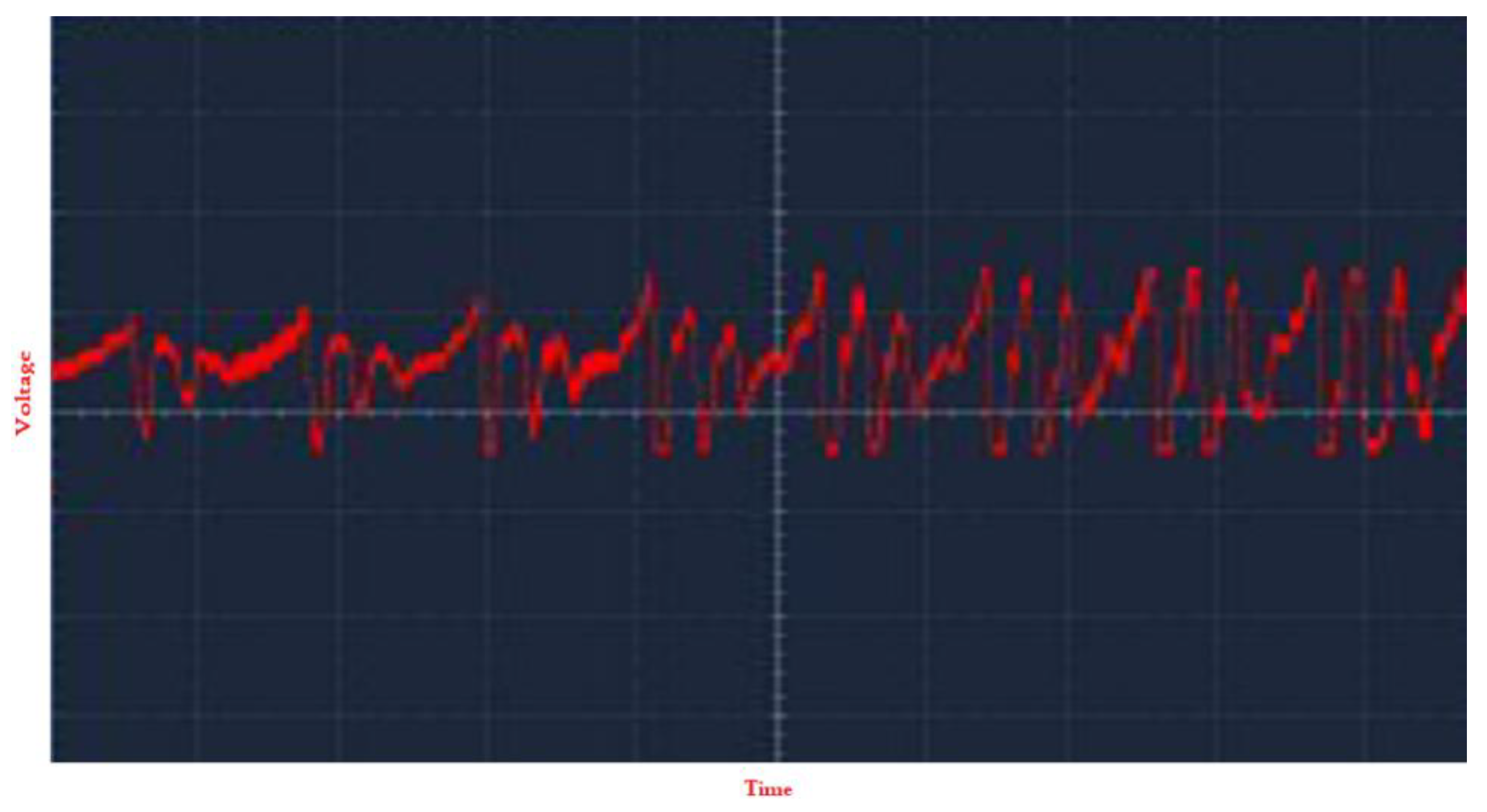
Figure 12 represents the amplified output signal from the second amplifier.
Figure 13 depicts the output signal after it is fed into the microcontroller and collected from the serial output of the microcontroller. This output is then fed to the 8-bit PIC16F876 Microcontroller, a 28-pin microcontroller [
45]. The microcontroller output is then sent to the Zigbee transmitter.
Figure 14 and
Figure 15 depict the waveforms at various receiver section terminals. Zigbee receives and demodulates the received signal at the receiver end. The Zigbee signal ranges between 0 and 3.3 volts [
46].
Table 4 shows the Zigbee pin description on the receiver section.
The microcontroller cannot operate on a 3.3 V data signal; hence the signal needs to be amplified. This is achieved by using IC MAX 232 [
47]. The pin description of IC MAX232 implemented in this section is shown in
Table 5.
The output produced by MAX 232 is a digital signal. This signal has an amplitude that alters between 0 Volts and 5 Volts [
48]. This signal is then fed as an input to the microcontroller.
The pins of the microcontroller are described in
Table 6.
The output from the tiny microcontroller can be collected from pin 13 and demodulated using a low pass filter. Switch S controls R-2-R and PWM [
49]. This signal is passed through the first amplifier and then through the second amplifier, which produces a voice signal, which is then passed to the speaker, depending on the position of the switch.
Figure 14 represents the output signal from the receiver’s Zigbee unit.
Figure 15 represents the signal’s waveform to be fed into the microcontroller.
Figure 16 represents the output PWM signal from the microcontroller.
We selected a speech codec for high-quality voice transmission over Zigbee and investigated many aspects of the process [
50,
51] as shown in
Figure 17 and
Figure 18. A G.729 variant appeared to be the original “natural” choice for an 8-kbps codec. Because we could not afford a commercial product, we turned to the open-source community, where many high-quality alternatives. According to the findings of the porting effort, an integrated Zigbee-based wireless headset can use a narrow-band codec with strict low-power and bandwidth requirements. All analog interfaces were also included in our design, which is extremely useful. This section also briefly reports the results of the embedded system transmission range and power consumption testing, as well as the Z-Phone headset [
51]. According to the literature, this is one of the few professional engineering efforts that has successfully ported a (royalty-free) speech codec to an ultra-low-power DSP, enabling voice communications in limited ultralow-power devices and networks.
5. Conclusions
The prototype was rigorously tested and performed wonderfully up to a distance of 25 m. The contributions to the research give an efficient way for wireless voice communication via low-power microcontrollers. This system shows operating facts about the network, such as wireless voice communication. This effort was done to minimize the total cost of producing such gadgets that contribute to home automation systems and other related initiatives. The primary purpose of the project was to use Zigbee to communicate voice through low-power microcontrollers such as 8-bit microcontrollers. Zigbee is presently supported only on 32-bit microcontrollers and not on low-power microcontrollers. This paper’s major purpose is to implement Zigbee with an 8/16-bit microcontroller to decrease complexity, cost, processing power, and power consumption. We study the feasibility of using ZigBee technology to transmit speech in full-duplex mode for use with popular VoIP apps in this article. We intended to create a wireless network that is low-cost, cheap, uses minimal power, and has a long range. Furthermore, it reveals how it arrived at its conclusion on the codec, including the factors considered, the specifics of the implementation, and the results. This work introduced and investigated a speech codec for high-quality ZigBee voice transmission. We study the feasibility of using ZigBee technology to transmit speech in full-duplex mode for use with popular VoIP apps in this article. We intended to create a wireless network that is low-cost, cheap, uses minimal power, and has a long range. Furthermore, it reveals how it arrived at its conclusion on the codec, including the factors considered, the specifics of the implementation, and the results. The talk also discussed an ultra-low-power DSP architecture with performance and memory restrictions. Such a porting effort demonstrates that a narrow-band codec may be employed in a ZigBee-based wireless headset with stringent low-power and bandwidth constraints. The outcomes of this study can assist any applications that require high-quality voice transmission across limited networks and utilize constrained devices.


