Article

Cyclic Behaviour of Heat-Damaged Beam−Column Joints Modified with Nano-Silica, Nano-Titanium, and Nano-Alumina

by
Yasmin Zuhair Murad
*,
Ahmad J. Aljaafreh
,
Ayoub AlMashaqbeh
and
Qusai T. Alfaouri
Civil Engineering Department, The University of Jordan, Amman P.O. Box 11942, Jordan
*
Author to whom correspondence should be addressed.
Sustainability 2022, 14(17), 10916; https://doi.org/10.3390/su141710916
Submission received: 20 July 2022 / Revised: 26 August 2022 / Accepted: 27 August 2022 / Published: 1 September 2022
(This article belongs to the Section Sustainable Materials)

Abstract

:
This research is designed to check the potential of modifying concrete with nanomaterials to enhance the cyclic behavior of beam−column joints. It also studies the effect of heat on the cyclic behavior of beam−column joints modified with nanomaterials. Experimental and numerical programs are carried out to explore the cyclic behavior of the heat-damaged and unheated RC joints modified with nanomaterials. Six half-scale exterior RC beam-to-column joints were prepared; two control specimens, two specimens were modified with nano-silica and nano-alumina, and two specimens were modified with nano-silica and nano-titanium. The cement was replaced by 1.33% nano-alumina and 0.67% nano-silica (by cement weight), and the other concrete mix was modified with 1.33% nano-silica and 0.67% nano-titanium, where the cement was replaced by a total of 2% nano-alumina and nano-silica in two specimens, and a total of 2% nano-silica and nano-titanium in the other two specimens. One specimen from each concrete mix was subjected to a temperature of 720 °C for 2 h. The joint specimens were subjected to lateral cyclic loading on the beam and axial loading on the column. Test results showed that the replacement of cement with 2% nano-alumina and nano-silica or 2% nano-silica and nano-titanium is recommended to enhance RC joints’ behavior. The nanomaterials changed the mode of failure of the joint specimens from brittle joint shear failure to a combined type of failure involving the ductile beam hinge and joint shear.

1. Introduction

Concrete is the most widely used material in construction, but it is a brittle material. Several experimental studies were conducted to enhance its mechanical and durability properties. Nanotechnology has been recently applied in construction to enhance the properties of building materials. Recent studies have explored the addition of new high-performance materials, such as nanomaterials, to improve concrete mixes. The diameters of the nanoparticles vary between 0.1 to 100 nm, producing a high surface−volume relation [1]. Silva et al. [2] studied the effect of silica nanoparticles and aluminum nanoparticles on the shear and flexural behavior of reinforced concrete beams. They showed that the shear and flexural strength of RC beams increased with the addition of nanoparticles, where the increment in the strength is more obvious with the aluminum nanoparticles. Shekari and Razzaghi [3] experimentally investigated the mechanical properties of concrete made with Nano-ZrO2 (NZ), Nano-Fe3O4 (NF), Nano TiO2 (NT), and Nano-Al2O3 (NA). They showed that nanoparticles enhanced the compressive and tensile strengths of concrete and the maximum enhancement was measured with the addition of Nano-Al2O3 (NA).
Orakzai [4] studied the mechanical behavior of concrete prepared with the addition of nano-alumina and nano-titanium dioxide. It was found that the optimum percentage of nano-alumina and nano-titanium dioxide was 0.5% and 1% by cement weight, respectively. It was also shown that the addition of nano-alumina and nano-titanium dioxide increased the compressive, splitting tensile and flexural strength by 42%, 34%, and 28%, respectively. Rahman and Dev [5] utilized different percentages of nano-alumina in ordinary concrete to study their influence on the mechanical properties of concrete. They showed the addition of nano-alumina in any of the adopted percentages enhanced the mechanical properties of concrete.
Jian et al. [6] showed that cement pastes prepared with nano-alumina exhibited higher compressive strength at all time increments compared to cement pastes prepared with ordinary concrete. They explained the incremental increase in strength with the presence of nano-alumina due to the reduction in macropores and the accelerating effect on cement hydration motivated by nano-alumina. Mustafa et al. [7] showed that the replacement of cement with nano-silica, up to 2% of the cement weight, increased the compressive and flexural strengths of concrete, whereas increasing the replacement percentage beyond 2% has an insignificant effect on the compressive strength. They also showed that increasing the replacement percentage up to 3% decreased the compressive strength of concrete. Elkady et al. [8] studied the effect of indirect elevated temperature on the compressive and bond strengths of concrete made with three percentages of 1.5, 3, and 4.5% of nano-silica (NS). They showed that the dispersion of nano-silica significantly influenced the mechanical behavior of concrete, especially when using low percentages of NS. The bond strength was significantly improved with NS, but the bond strength rapidly deteriorated when the concrete was exposed to heat.
Shyamala et al. [9] showed that the addition of fly ash increased the flexural strength of the beam−column joint in a range of (20% to 40%), but it then decreased. They also found that the addition of nano-silica to concrete modified with fly ash enhanced the performance of the joint assemblage. Kantarcı and Maraş [10] used a geopolymer grout modified with nano-titanium for retrofitting damaged beam−column joints. They found that the geopolymer grout modified with nano-titanium increased the strength and ductility of the beam−column joint sub-assemblage. Saha and Prasad [11] used a one-pot hydrothermal synthesis of iron Fe2O3 nanoparticles to enhance the strength of beam−column joints subjected to cyclic loading. They found that the optimum percentage of Fe2O3 is 3%, which enhances the strength and energy absorption.
Murad et al. [12] tested several beam−column joint sub-assemblages prepared from concrete modified with pulverized fuel ash, silica fume, and iron filing, and then subjected them to cyclic loading. Two different percentages were used, 15% and 20%. They found that the optimum percentage was 15%, whereas increasing the replacement percentage to 20% reduced the concrete compressive strength, weakened the joint, and reduced its ductility. Beam−column joints prepared with 15% pulverized fuel ash has the best performance. Murad [13] found that fabric-reinforced cementitious matrix FRCM composites considerably enhanced the ductility, drift ratio, and initial stiffness of the joint specimens up to 166%, 66%, and 11%, respectively. Murad also recommended using the U-shaped configuration to increase the ductility of the joint. Murad and AlSeid [14,15] recommended CFRP ropes and polylactic acid and carbon fiber 3D printed bars to strengthen and repair RC joints subjected to cyclic loading. They found that CFRP ropes increased the load carrying capacity, drift ratio, and the ductility of the heat-damaged joint specimens up to 50%, 98%, and 53%, respectively. The 3D printed bars significantly improved the ductility of the heat-damaged RC joints up to 206%.
Nanomaterials can enhance the mechanical behavior of concrete if added in specific percentages. Limited studies investigated the experimental behavior of reinforced concrete beams, columns, and joints modified with nanomaterials. Experimental studies that investigate the cyclic behavior of unheated or heat-damaged beam−column joints modified with nanomaterials are limited in the literature. This research aims to study the cyclic behavior of beam−column joints modified with different types of nanomaterials. Six joint specimens were prepared, where three specimens were subjected to a heat of 720 °C for 3 h before being tested, while the other three specimens were tested at room temperature. Three concrete mixes were used for the beam−column joint specimens, including plain concrete, concrete modified with nano-alumina and nano-silica, and concrete mix modified with nano-silica and nano-titanium. The cement weight was replaced by 2% nano-alumina and nano-silica and 2% nano-silica and nano-titanium. Stirrups were excluded from the joint panel to promote joint shear failure in order to check the effect of nanomaterials on changing the mode of failure of the beam−column joints from the brittle to ductile type. Numerical and analytical studies were also developed to compare test results with those predicted using the analytical ACI-352 formulations and the numerical results obtained from ABAQUS (finite element modeling) to check their applicability for predicting test results.

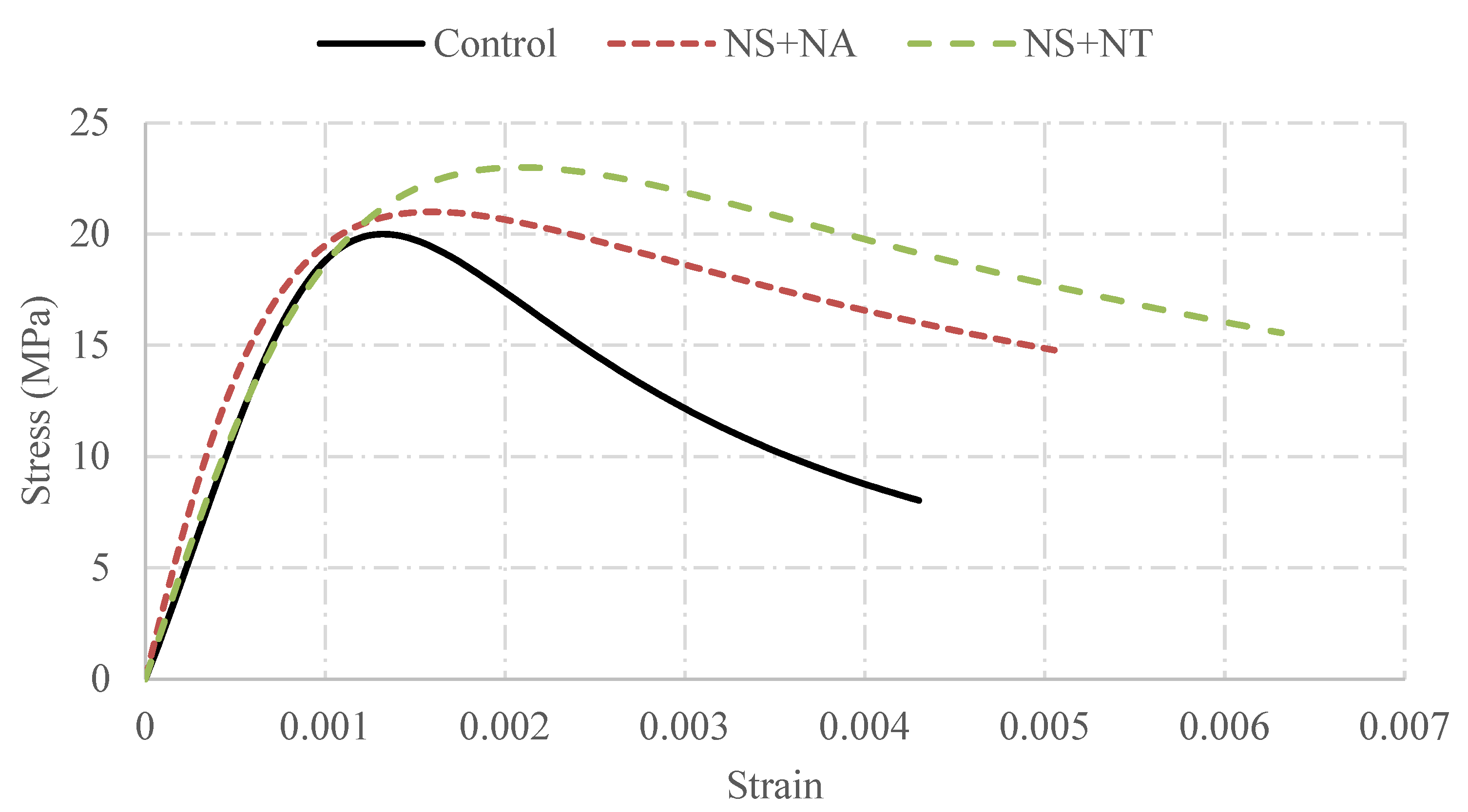
2. Material Properties

The mechanical behaviors of heat-damaged and unheated concrete and reinforcement utilized in the joint specimens are investigated in this section. Three concrete cylinders were prepared for each concrete mix and then tested according to the ASTM C39 [16] to measure the compressive strength of heat damaged and unheated plain concrete, concrete modified with 1.33% nano-alumina and 0.67% nano-silica, and concrete mix modified with 1.33% nano-silica and 0.67% nano-titanium. The cement was replaced by a total of 2% nano-alumina and nano-silica and a total of 2% nano-silica and nano-titanium. The reinforcement bars were also tested according to the ASTM A370 [17] standards. Table 1 summarizes the mechanical properties of concrete and reinforcement before and after subjecting them to heat. The average unheated compressive strengths of plain concrete (C20/25), concrete modified with nano-alumina and nano-silica, and concrete mix modified with nano-silica and nano-titanium are 18, 17, and 20 MPa, respectively, while the compressive strengths of the heated cylinders are 5, 8, and 9 MPa. The exposure of concrete to heat reduced its compressive strength due to the dehydration of cement paste that caused the loss of chemically combined water or hydration, reducing the bond strength between the paste and the aggregate. The experimental stress−strain curves of the three concrete mixes are shown in Figure 1. The average unheated yield and ultimate strengths of the B450C deformed steel bars (Φ = 10 mm) are 405 and 597 MPa, respectively, and the average heated strengths are 300 and 471 MPa, respectively. The mechanical properties of steel bars with different diameters are shown in Table 1. Heat deteriorates the mechanical properties of steel bars, resulting in a decrease in their strength.

3. Specimen Details

Half-scale beam−column joints were tested in this research under cyclic loading. The total number of joint specimens is six, which are distributed in three groups. The first group includes two typical control specimens prepared with plain concrete (C20/25), the second group has two typical specimens produced from concrete modified with nano-silica and nano-alumina, and the third group includes two specimens made from concrete mixed with nano-silica and nano-titanium. One specimen from each concrete mix was subjected to heat (720 °C for 2 h), while the others were tested under room temperature conditions of 25 °C and 40% relative humidity to investigate the influence of heat on each group. Test specimens have typical details and dimensions, as shown in Figure 2, where the dimensions of the beam are 150 × 200 × 665 mm3 and 150 × 175 × 1500 mm3 for the column. The reinforcement of the column comprises four 12 mm longitudinal bars and 8 mm transverse reinforcement spaced at 5 cm. The reinforcement of the beam consists of four 16 mm longitudinal bars and 8 mm transverse reinforcement spaced at 5 cm. Minimum spacing was used between the stirrups of the beam and column to avoid shear failure in them. The joint panel does not have any stirrups to promote joint shear failure in order to check the effect of nanomaterials on changing the mode of failure of the beam−column joints from the brittle to ductile type. This research is designed to check the potential of modifying concrete with nanomaterials for to enhance the cyclic behavior of beam−column joints; moreover, it studies the effect of heat on the cyclic behavior of beam−column joints prepared with concrete modified with nanomaterials. Therefore, an experimental program was conducted to investigate the effect of the nanomaterials on the cyclic behavior of heat-damaged and unheated beam−column joints.

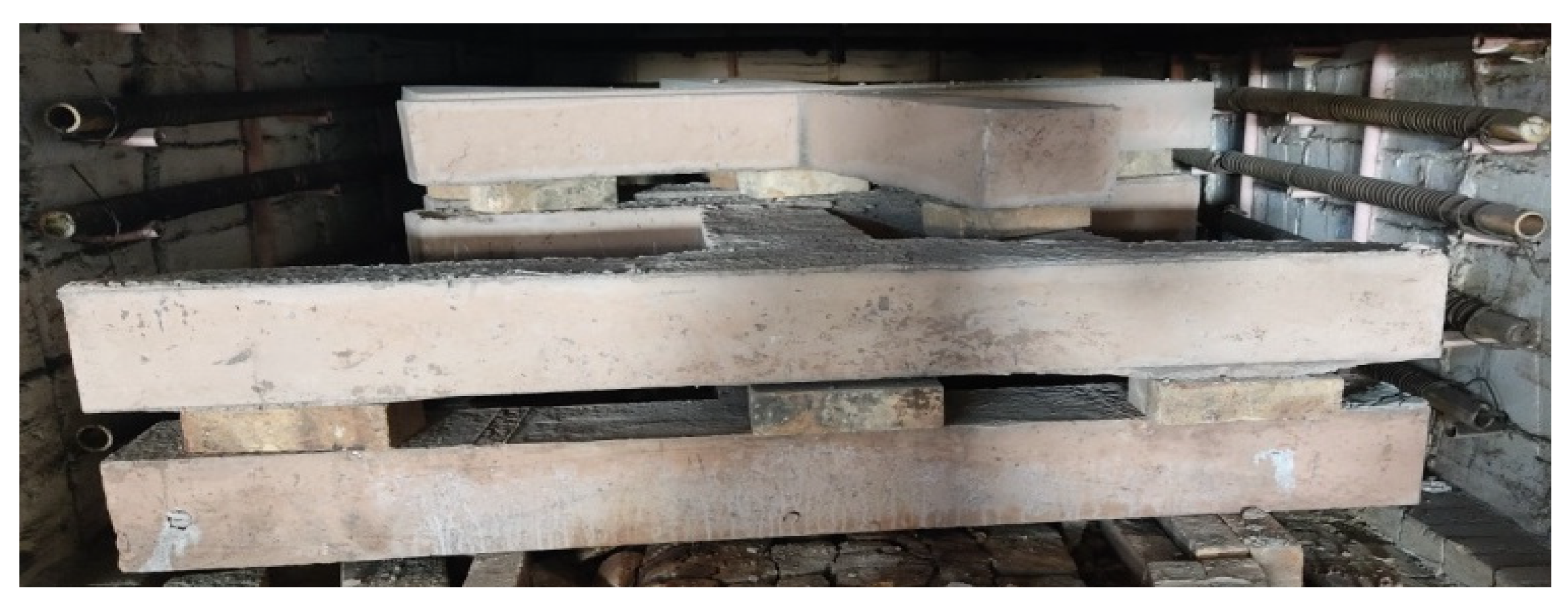
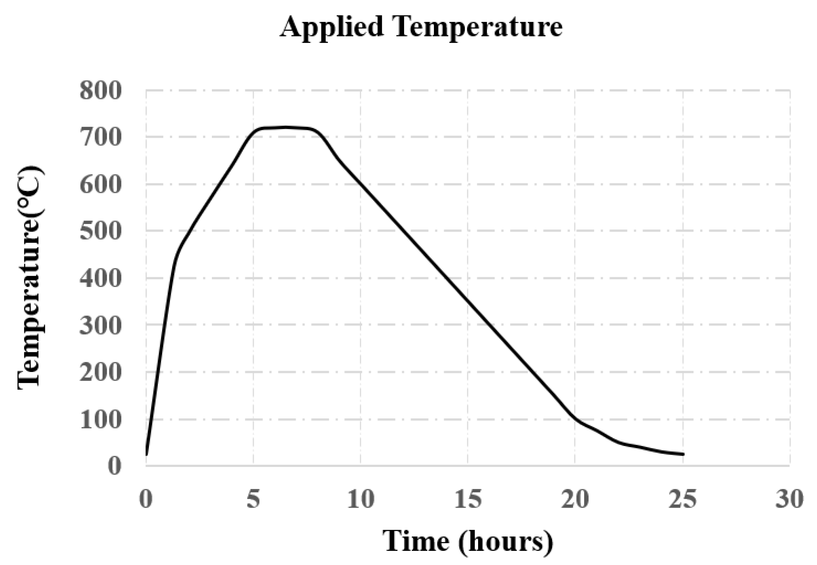
3.1. Heat Application

This research investigates the heat effect by subjecting three joint specimens to a temperature of 720 °C for 2 h, as shown in Figure 3. The heat curve was designed based on the ASTM-E119 [18], as shown in Figure 4. The concrete color was changed from grey to buff after subjecting the specimens to heat, as shown in Figure 3.

3.2. Cyclic Load Application

A quasi-static cyclic load was applied at the top of the beam, as shown in Figure 5 where the load rate was 0.5 kN/s. The load was applied according to the loading protocol of the ACI-374.1 [19], as shown in Figure 6. In order to study the loss of strength and stiffness in the recurring cycles of the test specimens, each loading cycle was repeated three times.

3.3. Test Setup

The test setup is clearly shown in Figure 5, where the column was placed in a horizontal position while the beam was placed vertically. A constant axial load of 0.125 f c A g was constantly applied along the column during the test where the adopted axial load is greater than the minimum value (0.1 f c A g ) specified by the ACI guidelines [20]. Lateral cyclic loads were applied at the tip of the beam through a hydraulic actuator and linear variable differential transducers (LVDTs) were fixed at the tip of the beam to measure the lateral displacement of the beam tip. The joint shear strain was also measured using two LVDTs that were diagonally fixed in the joint panel, as shown in Figure 5.

4. Analytical Background

The load carrying capacity was predicted in this section for the joint specimens according to the ACI-352 [21] guidelines using the mechanical properties of the unheated and heat-damaged concrete and reinforcement bars, illustrated in Table 1. The contribution of stirrups was ignored because the joint panel of the test specimens was unconfined by stirrups. Therefore, the joint shear strength of the test specimens was predicted from the concrete contribution (Vc) only. A comparison is made in Table 2 between the predicted and experimental joint shear strength values. Equation (3) was used to predict the experimental joint shear strength based on the experimental applied lateral load. It should be noted that ACI-352 [21] guidelines underestimate the experimental results.
The nominal shear strength is
V n = ( V c + V s )
The shear contribution of the concrete (Vc) is
V c = 0.083 γ b j h c f ´ c
V s = 0   ( No stirrups in the joint panel )
V j h = T b V c o l = P [ L p j d L p + 0.5 h c H c ]

5. Finite Element Modeling

This study performed numerical modeling for all test specimens using ABAQUS [22]. The mesh size was selected after performing a sensitivity analysis. Concrete and reinforcement were modeled in ABAQUS using C3D8R and T3D2, respectively. The C3D8R is a 3D, general purpose, linear, brick, solid element with reduced integration (one integration point) where it has eight nodes. This concrete model has three degrees of freedom that allow translations in X, Y, and Z directions at each node where this model was adopted to prevent the shear locking effect. T3D2 is a two-node, linear, 3D truss element that also has three degrees of freedom at each node. Steel bars were embedded in concrete with the same degree of freedom to ensure a perfect bond between concrete and reinforcement. The adopted solver in ABAQUS was the Newton−Raphson method, which allows convergence at the end of each load increment within tolerance limits.

5.1. Material Constitutive Behavior

5.1.1. Concrete Model

The concrete damage plasticity model (CDP) was adopted to simulate the constitutive behavior of concrete in ABAQUS [22]. The CDP model was first developed based on the models proposed by Lubliner et al. [23] and Lee and Fenves [24]. The CDP model is a plasticity-based model developed using concepts of continuum damage mechanics with scalar-damaged elasticity in combination with isotropic tensile and compressive plasticity. The model assumes that concrete has two principal failure mechanisms, which are compressive crushing and tensile cracking. The CDP model considers the softening effect in concrete with two damage parameters dt for tension and dc for compression. The damage parameters have values from zero to one, where zero refers to the undamaged material, and one means the total loss of strength [22]. Stiffness recovery is accounted for in this model during load reversals. It should be noted that the plasticity parameters and the damage parameters were selected to fit the experimental results. The plasticity parameters were taken as follows: the dilation angle = 30°, the eccentricity = 0.1, the elastic constitutive stiffness of the cohesive element (K) = 0.667, and the ratio of biaxial compressive strength to uniaxial compressive strength (fb0/fc0) = 1.16.

5.1.2. Reinforcement Model

The constitutive behavior of the longitudinal and transverse reinforcement was simulated using an elastic, perfectly plastic model that assumes that reinforcement does not harden after yielding.

5.2. Temperature Effect

The effect of temperature was simulated in ABAQUS [22] using the experimental stress−strain curves of the heat-damaged concrete and reinforcement. The implemented stress−strain curves were extracted from the test results of the compression and splitting tensile strength tests for the heat-damaged concrete cylinders and the reinforcement bars, respectively. The material tests were performed after exposing the concrete cylinders and the reinforcement bars to a temperature of 720 °C for 2 h, according to the heat curve shown in Figure 3.

6. Test Results and Discussion

An experimental program was conducted for exterior joint specimens subjected to lateral cyclic loading at the tip of the beam and a compressive axial loading at the column. The applied loading scheme simulates seismic loading in RC structures by repeating each lateral loading cycle three times, as shown in Figure 6. The cyclic behavior of beam−column joints prepared with concrete modified with three different types of nanomaterials was investigated. Three concrete mixes were prepared using ordinary concrete, concrete modified with nano-silica and nano-alumina, and concrete mix modified with nano-silica and nano-titanium. Heat effect was also investigated by subjecting a joint specimen from each concrete mix to a temperature of 720 °C for 2 h before being tested under cyclic and axial loadings. The efficiency of nanomaterials in enhancing the cyclic behavior of heat-damaged and unheated beam−column joints was investigated. The ACI-352 [21] guidelines were used to predict the joint shear strength of the test specimens based on the mechanical properties obtained from the materials test of the concrete cylinders and reinforcement bars. A comparison is made in Table 2 between the experimental and analytical results, showing that the ACI guidelines underestimate the joint shear strength. The joint shear strength values, given in Table 2, are the nominal values (without the strength reduction factor). This section compares the behaviors of beam−column joint specimens prepared with ordinary concrete and those modified with nanomaterials. Therefore, the equivalent viscous damping index, displacement ductility index, dissipated energy, initial stiffness, drift ratio, and envelope curves are calculated for all test specimens. The test also depicted the load at the first crack and the peak absolute shear strain. Test results are summarized in Table 3, including the peak load, peak displacement, maximum displacement, initial stiffness, ductility index, joint shear strain, drift ratio, and the load at the first crack. The drift ratio in this research equals the measured maximum lateral deflection divided by the distance between the lateral load point and the column centerline. The variation in the test results compared to the unheated control joint specimen is illustrated in Table 4.

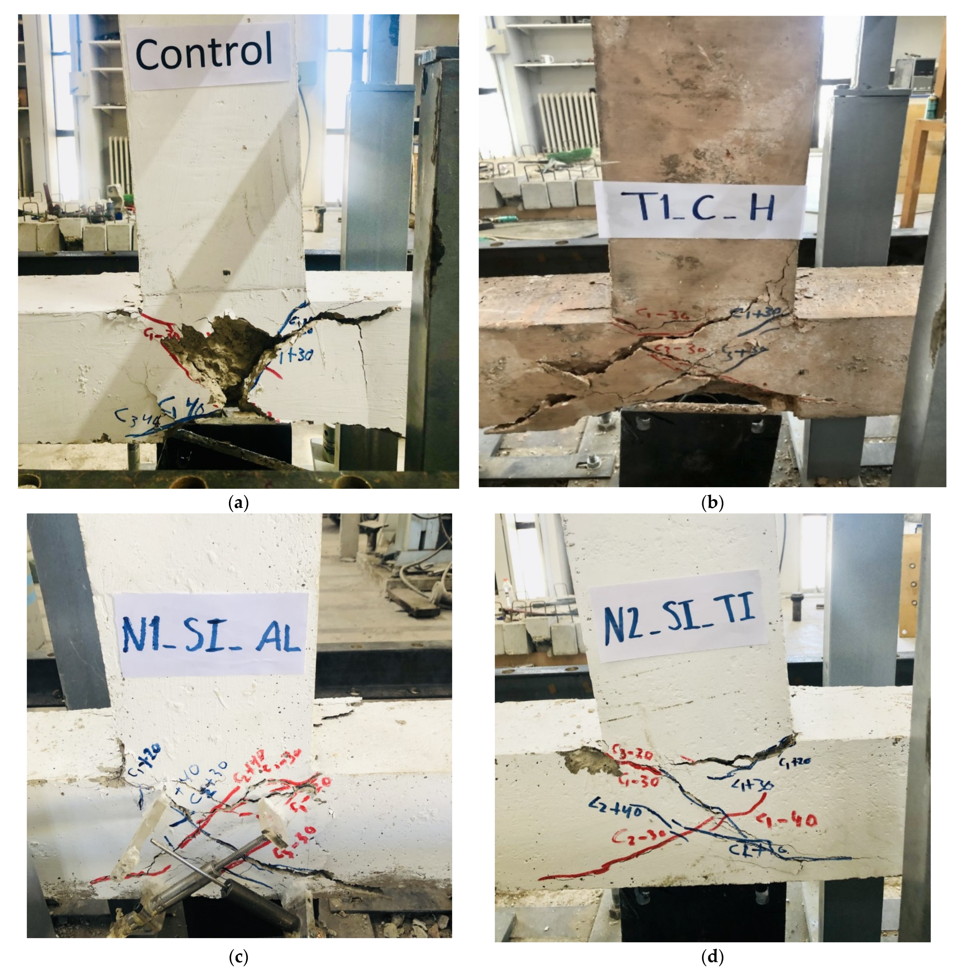
6.1. The Unheated Control Specimen

This specimen is an unheated control joint specimen prepared using ordinary concrete and designed according to the details provided in Figure 2. The joint panel of this specimen was not confined with stirrups to promote joint shear failure, which is the most common type of failure in non-ductile joints in old RC structures. Figure 7a shows that the control specimen failed under pure joint shear as expected, where the maximum lateral load-carrying capacity at failure was 50 kN. The relation between the lateral load and the lateral displacement of the control specimen is depicted in Figure 8a, where the maximum lateral displacement is 34.9 mm. The first crack appeared at the first loading cycle of the 20 kN. The drift ratio, ductility index, initial stiffness, and the absolute joint shear strain for this specimen were 4.6%, 2%, 2.9 kN/mm, and 0.051.

6.2. The Heated Control Specimen T1-C-H

This control specimen was prepared with ordinary concrete but was subjected to a temperature of 720 °C for 2 h based on the heat curve given in Figure 4 before being tested. RC structures can be subjected to fire attack; therefore, this specimen was designed to study the heat effect on the cyclic behavior of beam−column joints in these structures. Furthermore, it is the reference specimen for the joint specimens prepared with concrete modified with nanomaterials. It enables the investigation of the effect of heat on the cyclic behavior of heat-damaged beam−column joints modified with nanomaterials.
A comparison between the experimental cyclic behaviors of the unheated and heat-damaged control specimens is shown in Table 4 and Figure 8a,b. The lateral load carrying capacity and the maximum lateral deflection were decreased by 20% and 27%, respectively, due to the heat effect. Heat has an adverse effect on the cyclic behavior of exterior beam-to-column joints. Heat also decreased the drift ratio, initial stiffness, and displacement ductility index by 27%, 25%, and 34%, respectively. Figure 7b shows that this specimen failed due to pure joint shear.

6.3. Specimen N1-SI-AL

Specimen N1-SI-AL was prepared from concrete modified with nano-silica and nano-alumina, where 2% of the cement weight was replaced by nano-silica and nano-alumina. The replacement of cement with 2% of nano-silica and nano-alumina increased the ductility of the specimen, where the ductility index was increased up to 30%. The enhancement in the ductility resulted in a combined type of failure of the beam hinge and joint shear failure, as depicted in Figure 7c. The load carrying capacity, maximum displacement, and drift ratio decreased by 20%, 22%, and 22%, respectively. Figure 8c illustrates the experimental hysteresis response of this specimen.

6.4. Specimen N2-SI-TI

The cement in the concrete mix of this joint specimen was replaced by 2% nano-silica and nano-titanium of the cement weight. The resulting modified concrete mix increased the initial stiffness and ductility of the joint specimen up to 25% and 13%, respectively. The increment in the ductility changed the mode of failure from pure joint shear failure depicted in the control specimen to a combined type of failure of the beam hinge and joint shear captured in this specimen, as shown in Figure 7d. The load carrying capacity of this specimen was not decreased by the addition of the nano-silica and nano-titanium. However, the load carrying capacity of specimen N1-SI-AL, prepared from concrete modified with nano-silica and nano-alumina, was reduced by 20%. The replacement of cement with 2% nano-silica and nano-titanium reduced the drift ratio and the maximum deflection by 27%. The cyclic load and deflection curve of this specimen is shown in Figure 8d.

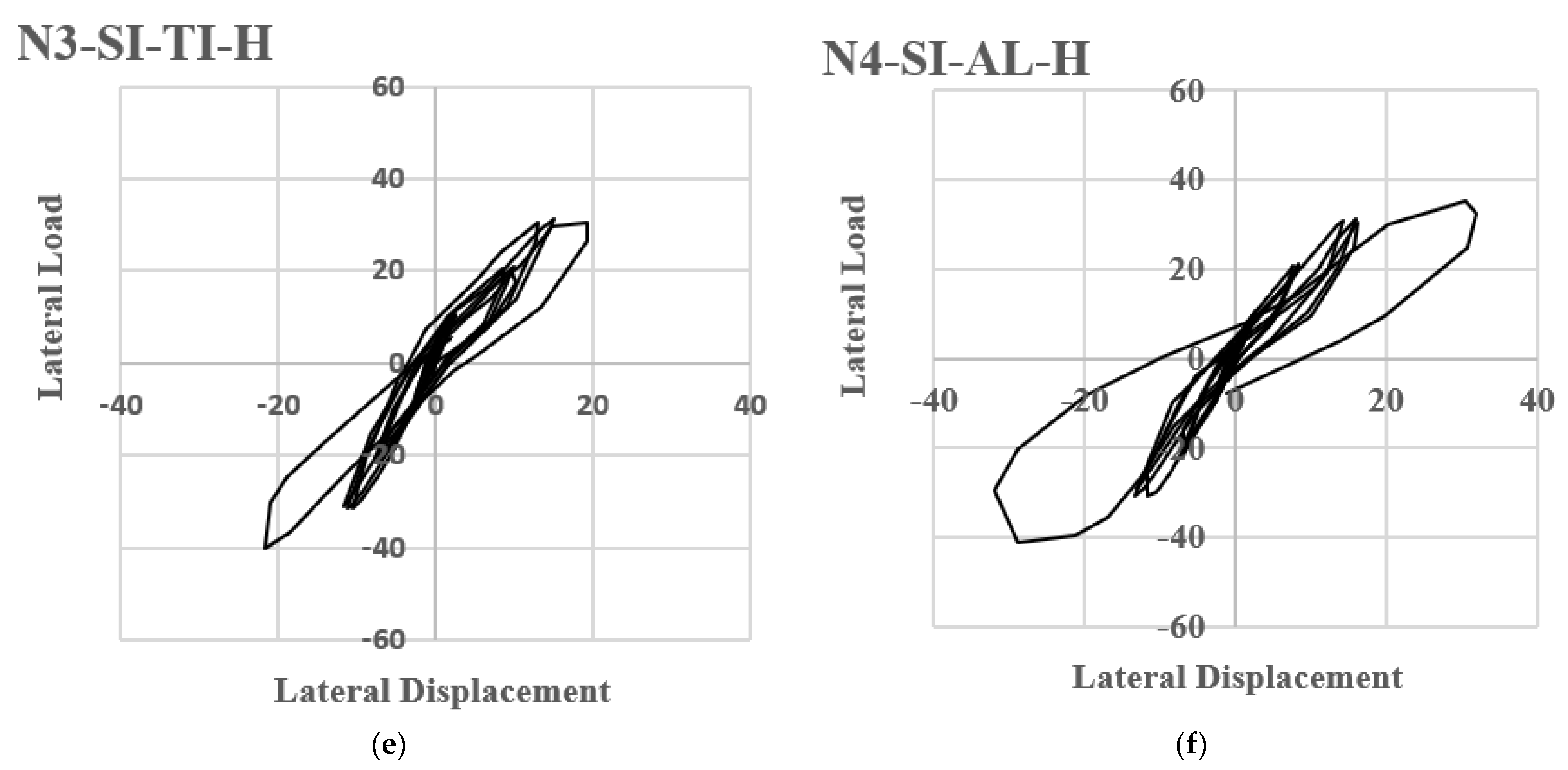
6.5. Specimen N3-SI-TI-H

This specimen was prepared from the same concrete mix of specimen N2-SI-TI where cement was replaced by 2% nano-silica and nano-titanium of the cement weight, but it was subjected to a temperature of 720 °C for 2 h before being tested. The heat was applied based on the heat curve shown in Figure 4. This specimen was designed to check the efficiency of the utilized nanomaterials in improving the cyclic behavior of the heat-damaged joint specimen. Heat reduced the lateral load carrying capacity by 20% compared to the unheated control specimen and the unheated specimen N2-SI-TI. The drift ratio and the maximum lateral deflection were significantly reduced in this specimen by 38% compared to the control specimen. In comparison, they were reduced by 15% compared to the unheated specimen N2-SI-TI due to heat. The initial stiffness was reduced by 14% compared to the unheated control specimen and by 31% compared to the unheated specimen N2-SI-TI due to heat. The ductility index was reduced by 7% compared to the unheated control specimen, promoting beam hinge and joint shear failure in the joint panel, as shown in Figure 7e. The hysteresis response of this specimen is depicted in Figure 8e.

6.6. Specimen N4-SI-AL-H

Specimen N4-SI-AL-H and specimen N4-SI-AL-H were prepared from the same concrete mix, where cement was replaced by 2% nano-silica and nano-alumina of the cement weight. In order to check the effect of heat on concrete modified with nano-silica and nano-alumina, specimen N4-SI-AL-H was exposed to a temperature of 720 °C for 2 h. The implementation of the nanomaterials in the concrete mix increased the ductility index up to 16% compared to the ordinary unheated specimen. The increment in the ductility changed the mode of failure from pure joint shear to a combined type of joint shear and beam hinge, as depicted in Figure 7f. However, heat reduced the ductility index of this specimen by 12% compared to the unheated specimen N4-SI-AL made from the same concrete mix. The initial stiffness was reduced by 27% compared to the unheated control specimen and by 34% compared to the unheated specimen N4-SI-AL due to heat. The drift ratio decreased by 8.5% compared to the control specimen. The increment of the nanomaterials did not recover the load carrying capacity of the unheated control specimen. The load carrying of the heat-damaged and unheated joint specimens modified with 2% nano-silica and nano-alumina were the same, which indicates that concrete modified with nano-silica and nano-alumina has superior strength properties to that modified with nano-silica nano-titanium when subjected to heat. The increment in strength with the presence of nano-alumina occurred due to the reduction in macropores and the accelerating effect on cement hydration motivated by nano-alumina. The hysteresis behavior of this specimen is depicted in Figure 8f.

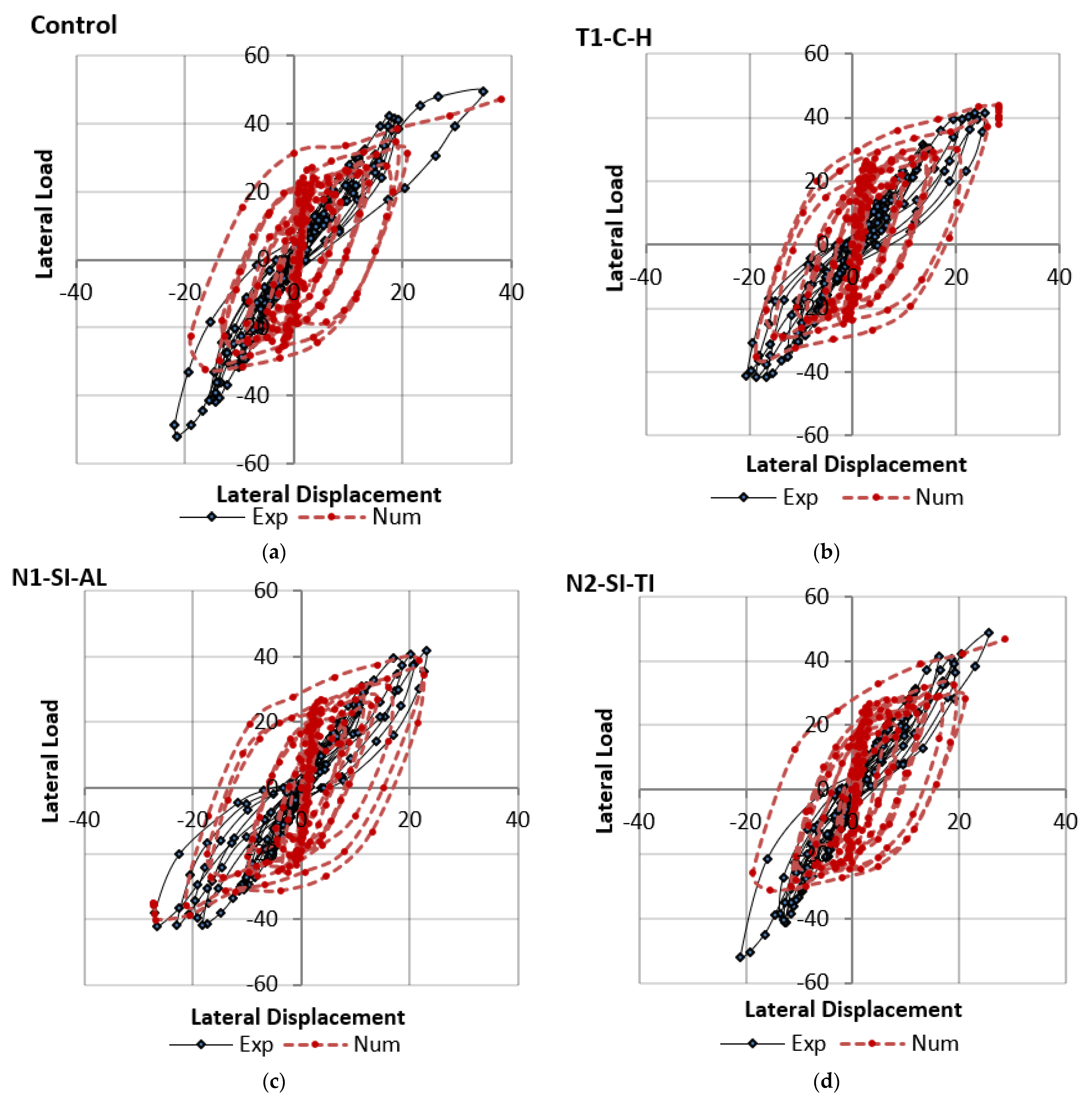
7. Experimental and Numerical Behaviours

This section compares the experimental and numerical behaviors of all joint specimens. The experimental and numerical hysteresis behaviors are close, as shown in Figure 9 for all test specimens. Furthermore, the experimental and numerical crack zones are also close, as shown in Figure 10, indicating that the ABAQUS model was satisfactorily able to predict the observed behavior of the test specimen.

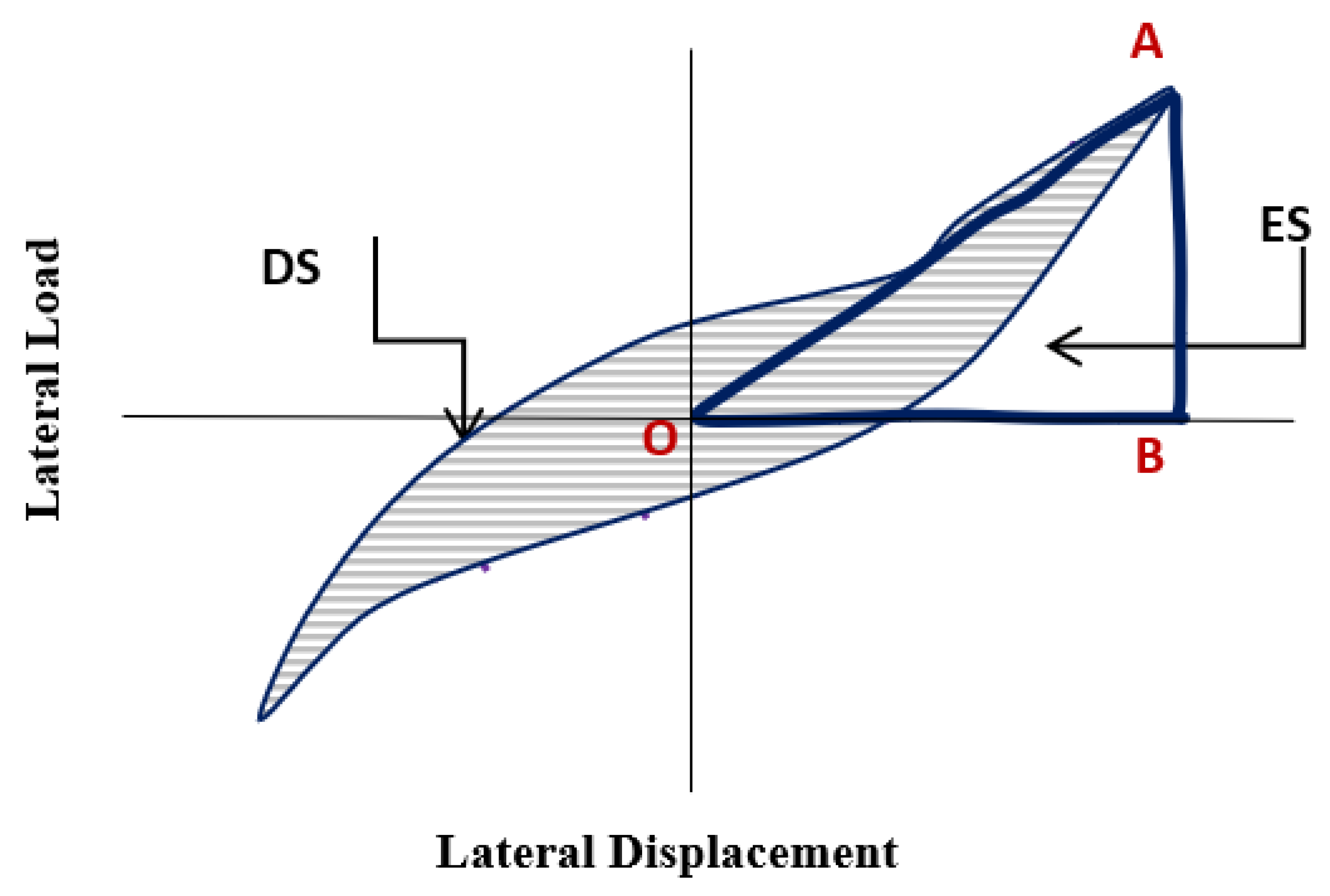
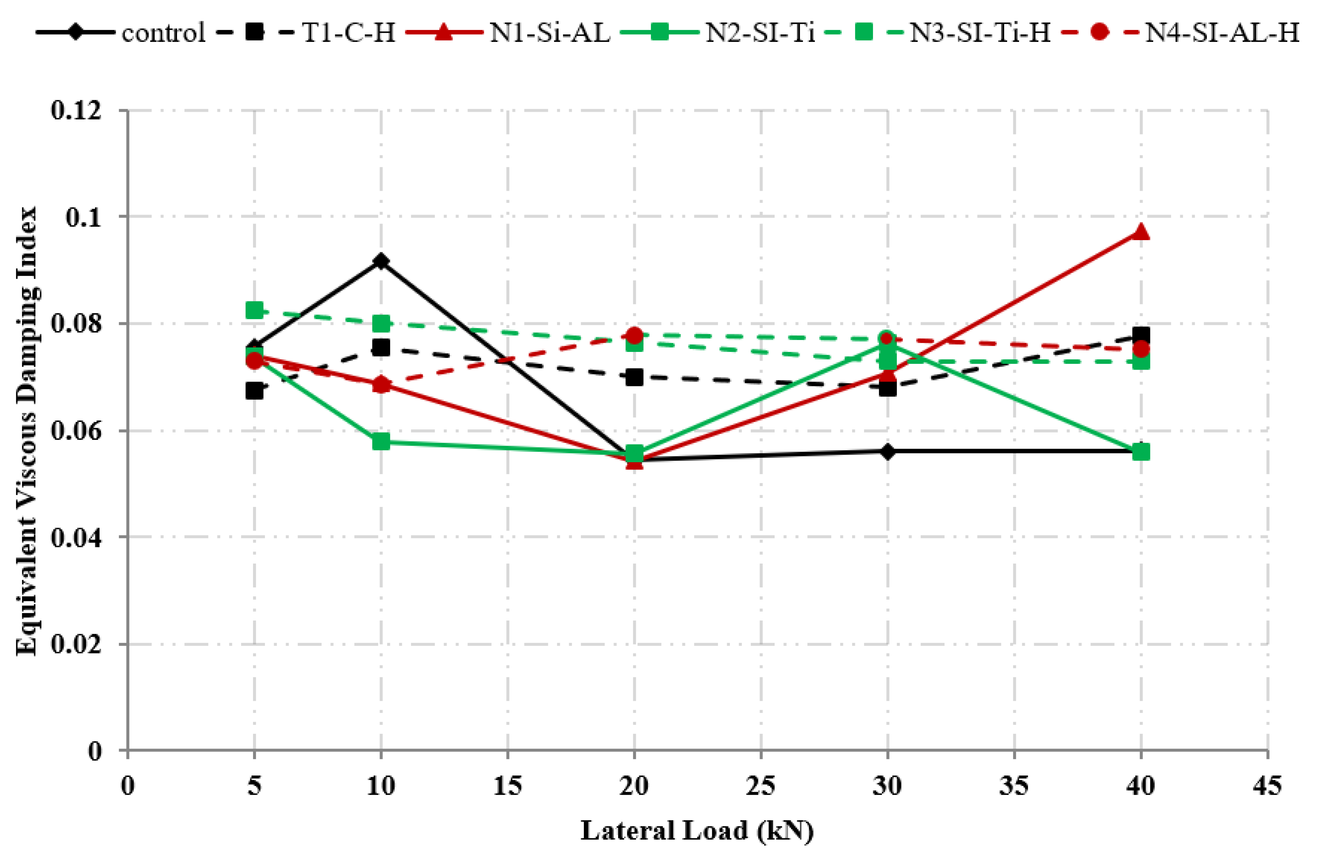
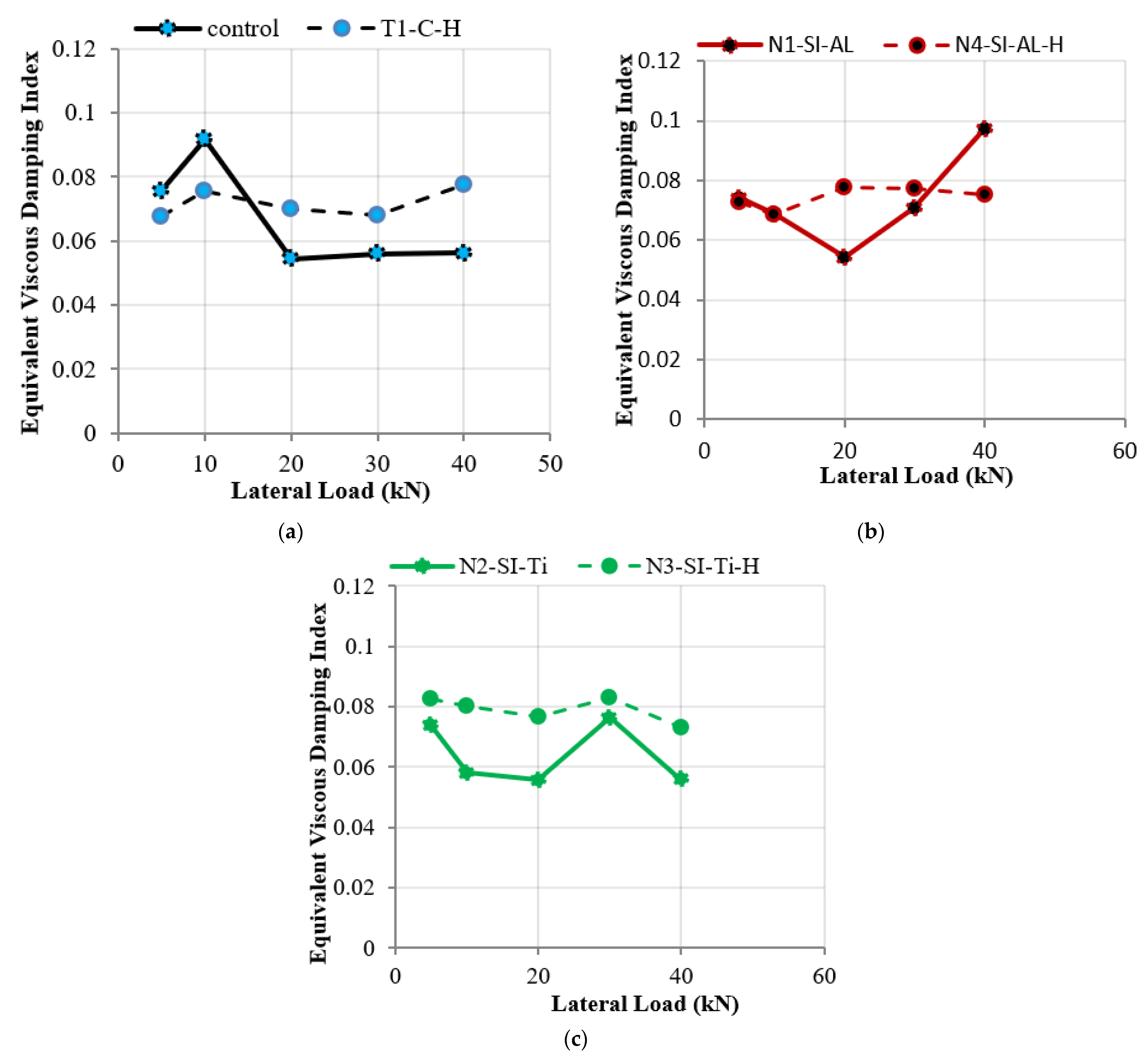
8. The Equivalent Viscous Damping Index

This section investigates the damage level at several loading steps at the first cycle of each load increment. This is an important measure to understand the behavior of RC joints at each loading increment. The displacement ductility index by Park and Ang [25], the dissipated energy, and the equivalent viscous damping index were used in this research to evaluate the damage level at each loading increment. The equivalent viscous damping index is an indicator of the capacity of the element and the dissipated energy before failure. It is evaluated by measuring the dissipated energy per each loading cycle and is defined in this research based on the following Chopra equation [26]:
ξ e q = W D S 4 π W E L
where ( ξ e q ) is the equivalent viscous damping index ( ξ e q ), (WDS) is the dissipated energy, and (WEL) is the maximum elastic strain energy. Figure 11 demonstrates the dissipated energy (WDS) and the maximum elastic strain energy (WEL). The area of the hysteresis loop in Figure 11 defines the dissipated energy, while the area of the triangle OAB defines the dissipated energy (WDS).
The equivalent viscous damping indices for all joint specimens are depicted in Figure 12 at the first cycle of each load increment. A comparison between the equivalent viscous damping indices for the heated and unheated joint specimens is shown in Figure 13, whereas the equivalent viscous damping indices of the control specimens are shown in Figure 13a. Figure 13b shows the equivalent viscous damping indices for specimens modified with nano-silica and nano-alumina. Figure 13c compares the equivalent viscous damping indices of the joint specimens modified with nano-silica and nano-titanium.
The equivalent viscous damping index in the joint specimens modified with nanomaterials is greater than that measured in the unheated control specimen at the failure cycles, as shown in Figure 12. The equivalent viscous damping of the RC joints modified with nano-silica and nano-alumina is greater than that measured in the RC joints modified with nano-silica and nano-titanium. It can also be seen from Figure 12 and Figure 13 that, generally, the equivalent viscous damping index of the heat-damaged beam-to-column joints is greater than that measured in the unheated RC joints and specifically at the failure cycle.

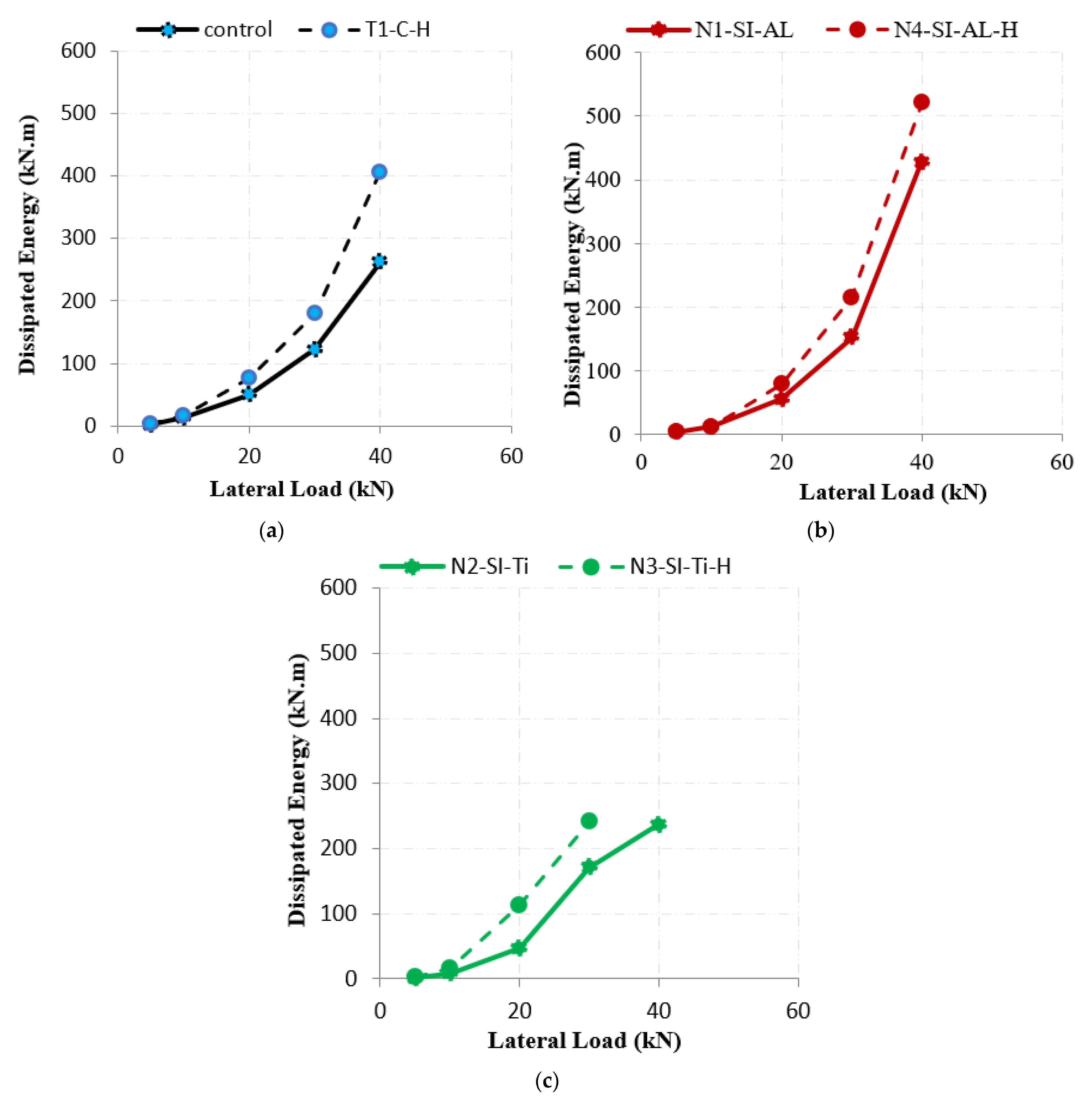
9. The Dissipated Energy

The dissipated energy for all test specimens is shown in Figure 14 at the first cycle of each load increment. Figure 14 shows that the dissipated energy of joint specimens modified with nanomaterials is greater than that measured in the unheated joint specimens stating that nanomaterials are efficient in restoring the energy dissipation capacity of the joints. The energy dissipation capacity of the RC joints modified with nano-silica and nano-alumina is greater than that measured in the RC joints modified with nano-silica and nano-titanium. Figure 15 illustrates that the dissipated energy of the heated specimens is greater than that measured in the unheated specimens because the heated specimens undergo large energy release and deformation before failure.

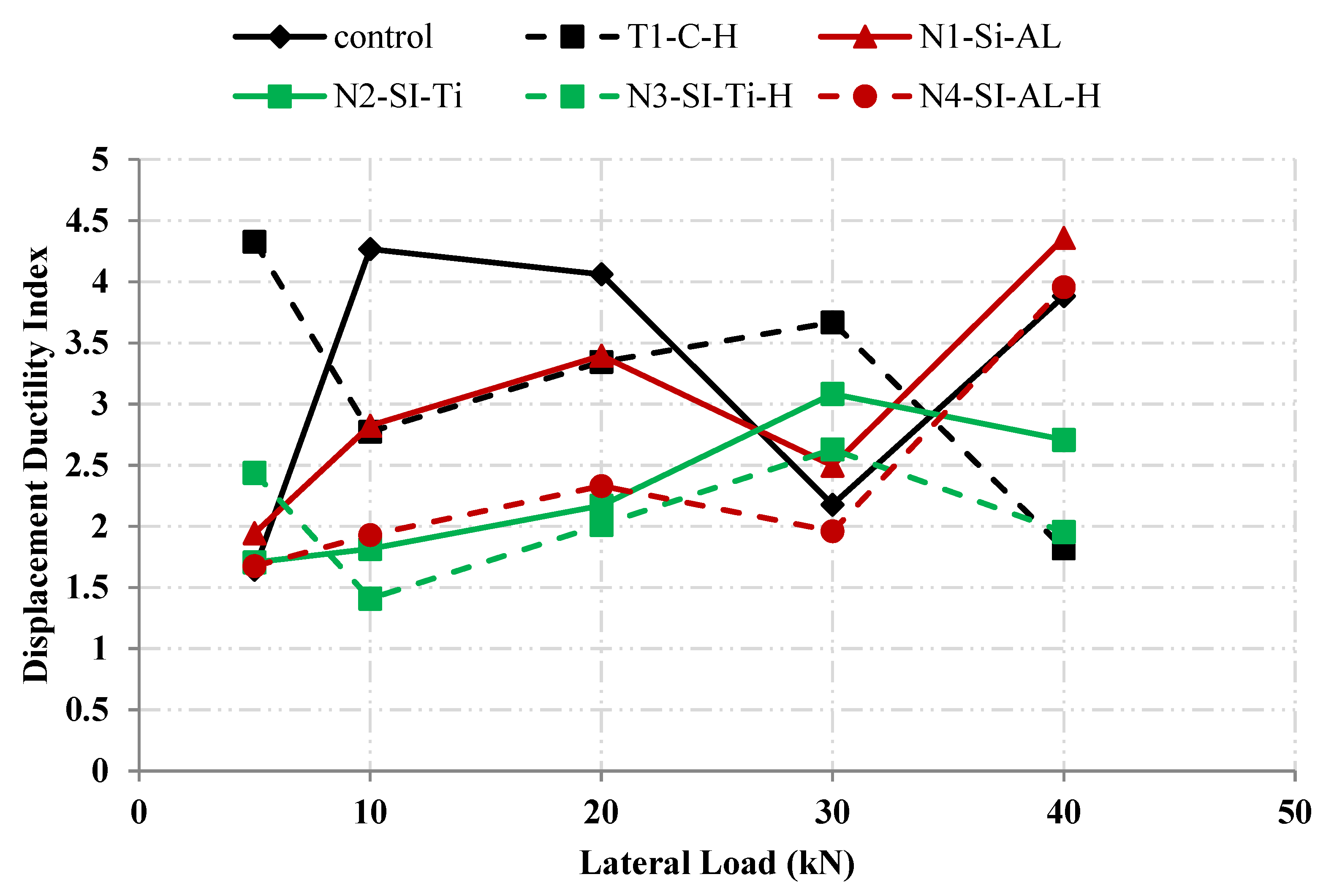
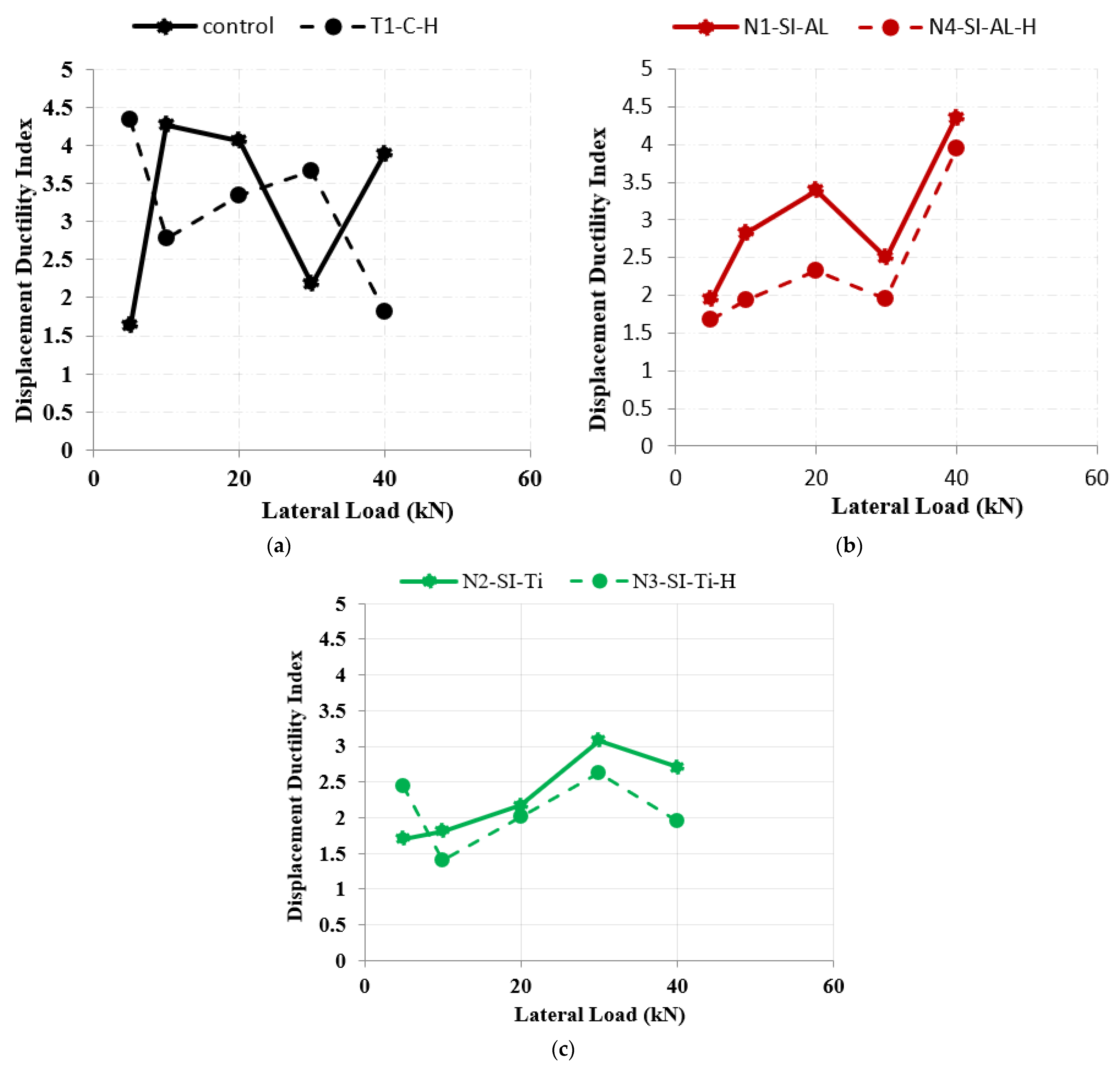
10. The Displacement Ductility Index

The damage index by Park and Ang [25] was adopted in this research to measure the displacement ductility index. Several researchers adopted the damage index by Park and Ang [25] due to its simplicity. The displacement ductility index by Park and Ang is measured by dividing the maximum deformation of members or structures over the yield deformation. It is used to evaluate the damage level in the structures at different loading steps, whereas the displacement ductility index is evaluated in this research at the first cycle of each load increment, as shown in Figure 16.
Figure 16 and Figure 17 show that the ductility index of the unheated specimen is less than that measured in the heated specimens. The displacement ductility index of the RC joints modified with nano-silica and nano-alumina is greater than that measured in the RC joints modified with nano-silica and nano-titanium.

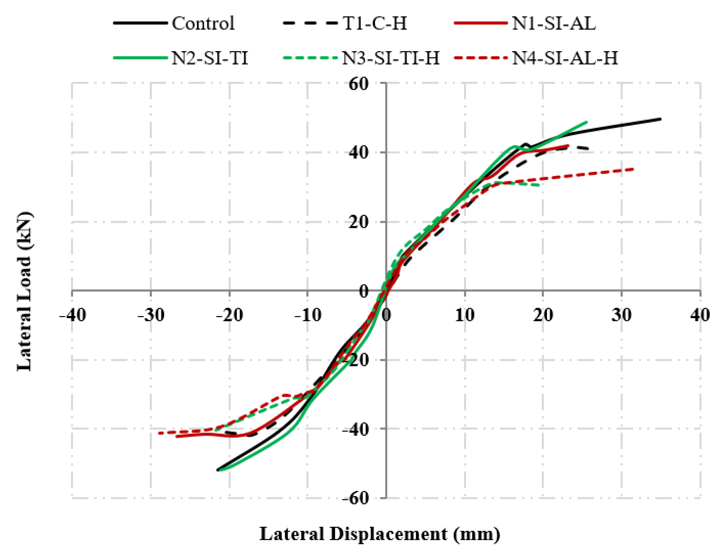
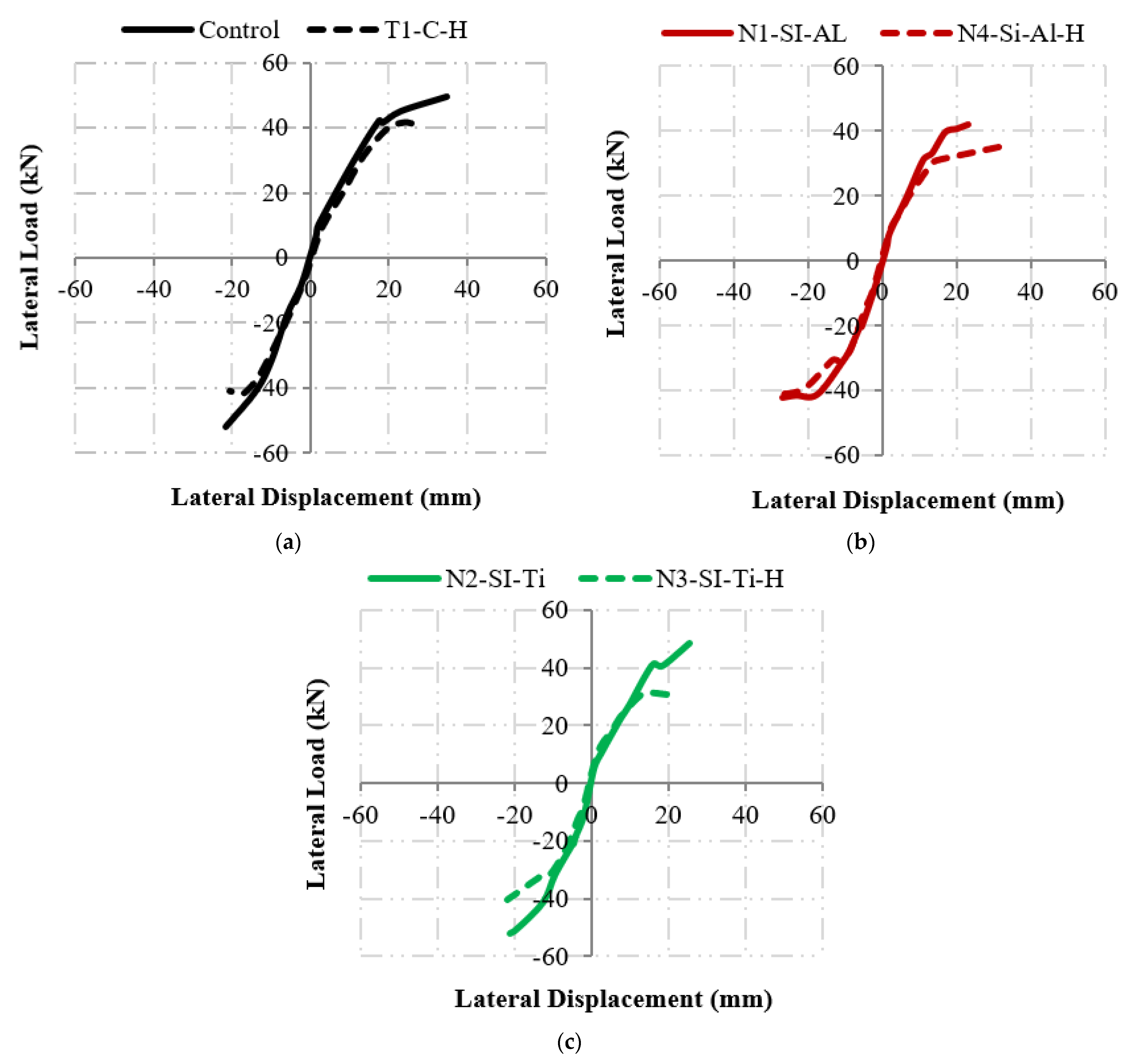
11. The Envelope Curves

The backbone curves of the hysteresis responses are the envelope curves, representing the test specimen’s capacity. Figure 18 demonstrates the envelope curves of all test specimens, and a summary is listed in Table 3. The envelope curves of the heated and unheated joint specimens are demonstrated in Figure 19. It can be seen from Figure 18 that the load carrying capacities of all heated specimens are less than that measured in the unheated specimens.

12. Conclusions

Experimental and numerical programs are conducted in this research to investigate the cyclic behavior of the heat-damaged and unheated RC joints modified with nanomaterials. Six half-scale exterior RC beam-to-column joints were prepared; two control specimens, two specimens were modified with nano-silica and nano-alumina, and two specimens were modified with nano-silica and nano-titanium. Cement was replaced by 2% of nano-silica and nano-alumina in two specimens, whereas it was replaced by 2% of nano-silica and nano-titanium in the other two specimens. One specimen from each group was subjected to a temperature of 720 °C for 2 h. The joint specimens were subjected to lateral cyclic loading on the beam and axial loading on the column. The research was carried out to check the efficiency of nanomaterials in enhancing the cyclic behavior of heat-damaged and unheated RC joints. It investigated the possibility of using nanomaterials in RC joints exposed to seismic loads. The following points summarize the research outcomes.
  • The replacement of cement with 2% nano-silica and nano-alumina or 2% nano-silica and nano-titanium is recommended to enhance RC joints’ behavior. It changed their mode of failure from brittle joint shear failure to a combined type of failure of the ductile beam hinge and joint shear.
  • The replacement of cement with 2% nano-silica and nano-alumina increased the ductility up to 30%. The enhancement in the ductility resulted in a combined type of failure of the beam hinge and joint shear failure.
  • The replacement of cement with 2% nano-silica and nano-titanium increased the initial stiffness and ductility of the joint specimen up to 25% and 13%, respectively.
  • The replacement of cement with 2% nano-silica and nano-titanium or 2% nano-silica and nano-alumina changed the mode of failure from pure joint shear failure to a combined type of failure of the beam hinge and joint shear.
  • The load carrying capacity of this specimen was not decreased by the addition of nano-silica and nano-titanium. However, the load carrying capacity of the joint specimens prepared from concrete modified with nano-silica and nano-alumina was reduced by 20%.
  • Heat reduced the load carrying capacity, ductility, deflection, and initial stiffness of the test specimens by 20%, 34%, 27%, and 25% in the control specimens.
  • The increment of the nanomaterials did not recover the load carrying capacity of the unheated control specimen. The load carrying of the heat-damaged and unheated joint specimens modified with 2% nano-silica and nano-alumina are the same, which indicates that concrete modified with nano-silica and nano-alumina has superior strength properties to that modified with nano-silica nano-titanium when subjected to heat.
  • Heat reduced the ductility of the joint specimens, where the reduction was the least in the joint specimen modified with 2% nano-silica and nano-alumina, and the specimen failed with a combined failure mode of the ductile beam hinge and joint shear.
  • ACI-440 guidelines underestimate the shear capacity of the RC joints modified with nanomaterials.

Author Contributions

Data curation, A.J.A., A.A. and Q.T.A.; Funding acquisition, A.J.A.; Investigation, A.A.; Methodology, Y.Z.M.; Software, A.J.A. and Q.T.A.; Supervision, Y.Z.M.; Writing—original draft, Y.Z.M.; Writing—review & editing, Y.Z.M. All authors have read and agreed to the published version of the manuscript.

Funding

This research was funded by [The University of Jordan] grant number [1].

Institutional Review Board Statement

Not applicable.

Informed Consent Statement

Not applicable.

Data Availability Statement

The raw/processed data required to reproduce these findings cannot be shared at this time due to technical or time limitations.

Conflicts of Interest

The authors declare no conflict of interest.

References

  1. Sanchez, F.; Sobolev, K. Nanotechnology in Concrete—A Review. Constr. Build. Mater. 2010, 24, 2060–2071. [Google Scholar] [CrossRef]
  2. Silva, J.V.; Ismael, R.; Carmo, R.N.F.; Lourenço, C.; Soldado, E.; Costa, H.; Júlio, E. Influence of Nano-SiO2 and Nano-Al2O3 Additions on the Shear Strength and the Bending Moment Capacity of RC Beams. Constr. Build. Mater. 2016, 123, 35–46. [Google Scholar] [CrossRef]
  3. Shekari, A.H.; Razzaghi, M.S. Influence of Nano Particles on Durability and Mechanical Properties of High Performance Concrete. Procedia Eng. 2011, 14, 3036–3041. [Google Scholar] [CrossRef]
  4. Atiq Orakzai, M. Hybrid Effect of Nano-Alumina and Nano-Titanium Dioxide on Mechanical Properties of Concrete. Case Stud. Constr. Mater. 2021, 14, e00483. [Google Scholar] [CrossRef]
  5. Rahman, I.; Dev, N. Nano Alumina Based High Strength Concrete. Int. J. Innov. Technol. Explor. Eng. 2020, 9, 2278–3075. [Google Scholar] [CrossRef]
  6. Zhan, B.J.; Xuan, D.X.; Poon, C.S. The Effect of Nanoalumina on Early Hydration and Mechanical Properties of Cement Pastes. Constr. Build. Mater. 2019, 202, 169–176. [Google Scholar] [CrossRef]
  7. Mustafa, T.S.; El Hariri, M.O.R.; Khalafalla, M.S.; Said, Y. Application of Nanosilica in Reinforced Concrete Beams. Struct. Build. 2021, 175, 363–372. [Google Scholar] [CrossRef]
  8. Elkady, H.M.; Yasien, A.M.; Elfeky, M.S.; Serag, M.E. Assessment of Mechanical Strength of Nano Silica Concrete (NSC) Subjected to Elevated Temperatures. J. Struct. Fire Eng. 2019, 10, 90–109. [Google Scholar] [CrossRef]
  9. Shyamala, G.; Kumarasamy, K.; Ramesh, S.; Kalaivani, M.; Pillalamarri, S.P. Influence of Nano-Silica in Beam-Column Joint Flextural Properties. IOP Conf. Ser. Mater. Sci. Eng. 2020, 872, 012169. [Google Scholar] [CrossRef]
  10. Kantarcı, F.; Maraş, M.M. Formulation of a Novel Nano TiO2-Modified Geopolymer Grout for Application in Damaged Beam-Column Joints. Constr. Build. Mater. 2022, 317, 125929. [Google Scholar] [CrossRef]
  11. Saha, P.; Prasad, M.L.V. The Influence of α-Fe2O3 Nanoparticles on the Reinforced Concrete Beam–Column Joint Under Cyclic Loading. Iran. J. Sci. Technol. Trans. Civ. Eng. 2022, 46, 2201–2216. [Google Scholar] [CrossRef]
  12. Murad, Y.; Abu-Haniyi, Y.; Alkaraki, A.; Hamadeh, Z. An Experimental Study on Cyclic Behaviour of Reinforced Concrete Connections Using Waste Materials as Cement Partial Replacement. Can. J. Civ. Eng. 2019, 46, 1–12. [Google Scholar] [CrossRef]
  13. Murad, Y.Z. Retrofitting Heat-Damaged Non-Ductile RC Beam-to-Column Joints Subjected to Cyclic and Axial Loading with FRCM Composites. J. Build. Eng. 2022, 48, 103952. [Google Scholar] [CrossRef]
  14. Murad, Y.Z.; Alseid, B.H. Retrofitting Interior RC Beam-to-Column Joints Subjected to Quasi-Static Loading Using NSM CFRP Ropes. Structures 2021, 34, 4158–4168. [Google Scholar] [CrossRef]
  15. Murad, Y.; Alseid, B. Poly-Lactic Acid and Carbon Fibers 3D Printed Bars for Seismic Retrofitting RC Beam-to-Column Joints Subjected to Elevated Temperature. Structures 2022, 43, 1530–1547. [Google Scholar] [CrossRef]
  16. ASTM C39/C39M-20; Standard Test Method for Compressive Strength of Cylindrical Concrete Specimens. American Society for Testing and Materials: West Conshohocken, PA, USA, 2020.
  17. ASTM A370-20; Standard Test Methods and Definitions for Mechanical Testing of Steel Products. American Society for Testing and Materials: West Conshohocken, PA, USA, 2020.
  18. ASTM E119-20; Fire Tests of Building Construction and Materials. American Society for Testing and Materials: West Conshohocken, PA, USA, 2020.
  19. ACI 374.1-05; Acceptance Criteria for Moment Frames Based on Structural Testing and Commentary. American Concrete Institute: Farmington Hills, MI, USA, 2005.
  20. ACI 318-19; Building Code Requirements for Structural Concrete (ACI 318-19) and Commentary. American Concrete Institute: Farmington Hills, MI, USA, 2019.
  21. ACI-352R-02; Recommendations for Design of Beam-Column Connections in Monolithic Reinforced Concrete Structures (ACI-352R-02). American Concrete Institute: Farmington Hills, MI, USA, 2002.
  22. Smith, M. Abaqus Analysis User’s Guide (6.14); Simulia: Providence, RI, USA, 2014. [Google Scholar]
  23. Lubliner, J.; Oliver, J.; Oller, S.; Oñate, E. A Plastic-Damage Model for Concrete. Int. J. Solids Struct. 1989, 25, 299–326. [Google Scholar] [CrossRef]
  24. Lee, J.; Fenves, G.L. Plastic-Damage Model for Cyclic Loading of Concrete Structures. J. Eng. Mech. 1998, 124, 892–900. [Google Scholar] [CrossRef]
  25. Park, Y.; Ang, A.H.-S. Mechanistic Seismic Damage Model for Reinforced Concrete. J. Struct. Eng. 1985, 111, 722–739. [Google Scholar] [CrossRef]
  26. Chopra, A. Dynamics of Structures: Theory and Applications to Earthquake Engineering; Prentice-Hall: Englewood Cliffs, NJ, USA, 1995. [Google Scholar]
Figure 1. The experimental stress−strain curves of the concrete mixes.
Sustainability 14 10916 g001
Figure 2. The typical dimensions and details of the joint specimens.
Sustainability 14 10916 g002
Figure 3. Joint specimens placed inside the furnace.
Sustainability 14 10916 g003
Figure 4. Applied temperature curve.
Sustainability 14 10916 g004
Figure 5. Test setup.
Sustainability 14 10916 g005
Figure 6. Applied load history.
Sustainability 14 10916 g006
Figure 7. The mode of failure and crack pattern of the test specimens. (a) Control; (b) T1-C-H; (c) N1-SI-AL; (d) N2-SI-TI; (e) N3-SI-TI-H; (f) N4-SI-AL-H.
Sustainability 14 10916 g007aSustainability 14 10916 g007b
Figure 8. The experimental behavior of the test specimens. (a) Control; (b) T1-C-H; (c) N1-SI-AL; (d) N2-SI-TI; (e) N3-SI-TI-H; (f) N4-SI-AL-H.
Sustainability 14 10916 g008aSustainability 14 10916 g008b
Figure 9. Experimental and numerical hysteresis behavior of test specimens. (a) Control; (b) T1-C-H; (c) N1-SI-AL; (d) N2-SI-TI; (e) N3-SI-TI-H; (f) N4-SI-AL-H.
Sustainability 14 10916 g009aSustainability 14 10916 g009b
Figure 10. The mode of failure and crack zone of the test specimens. (a) Control—Experimental; (b) Control—Numerical; (c) T1-C-H—Experimental; (d) T1-C-H—Numerical; (e) N1-SI-AL—Experimental; (f) N1-SI-AL—Numerical; (g) N2-SI-TI—Experimental; (h) N2-SI-TI—Numerical; (i) N3-SI-TI-H—Experimental; (j) N3-SI-TI-H—Numerical; (k) N4-SI-AL-H—Experimental; (l) N4-SI-AL-H—Numerical.
Sustainability 14 10916 g010aSustainability 14 10916 g010b
Figure 11. Illustration for the calculation of the equivalent viscous damping, DS: Dissipated energy, and ES: Elastic energy.
Sustainability 14 10916 g011
Figure 12. The equivalent viscous damping at the first cycle of each load increment for all test specimens.
Sustainability 14 10916 g012
Figure 13. The equivalent viscous damping at the first cycle of each load increment for the heated and unheated specimens (a) control, (b) nano-silica and nano-alumina, (c) nano-silica and nano-titanium.
Sustainability 14 10916 g013
Figure 14. The dissipated energy at the first cycle of each load increment for all test specimens.
Sustainability 14 10916 g014
Figure 15. The dissipated energy at the first cycle of each load increment for the heated and unheated specimens (a) control, (b) nano-silica and nano-alumina, (c) nano-silica and nano-titanium.
Sustainability 14 10916 g015
Figure 16. The displacement ductility index at the first cycle of each load increment for all test specimens.
Sustainability 14 10916 g016
Figure 17. The displacement ductility index at the first cycle of each load increment for the heated and unheated specimens (a) control, (b) nano-silica and nano-alumina, (c) nano-silica and nano-titanium.
Sustainability 14 10916 g017
Figure 18. The backbone envelope curves of all test specimens.
Sustainability 14 10916 g018
Figure 19. The envelope curves of the heated and unheated specimens (a) control, (b) nano-silica and nano-alumina, (c) nano-silica and nano-titanium.
Sustainability 14 10916 g019
Table 1. Mechanical properties of concrete and reinforcement before and after heat.
Mechanical PropertiesSpecimen 1
Unheated/Heated
Specimen 2
Unheated/Heated
Specimen 3
Unheated/Heated
Average
Unheated/Heated
Cylindrical concrete compressive strength (Control) MPa18.4/5.317.9/4.817.7/4.918/5
Cylindrical concrete compressive strength (Nano-silica and Nano-alumina) MPa16.6/7.517.3/8.517.1/817/8
Cylindrical concrete compressive strength (Nano-silica and Nano-titanium) MPa20.3/9.320/9.119.7/8.620/9
Reinforcement yield strength
(Φ = 10 mm) (MPa)
405/298406/300404/302405/300
Reinforcement ultimate strength
(Φ = 10 mm) (MPa)
597/471593/477601/465597/471
Reinforcement yield strength
(Φ = 12 mm) (MPa)
398/290400/295390/290396/292
Reinforcement ultimate strength
(Φ = 12 mm) (MPa)
587/461583/456550/420573/446
Reinforcement yield strength
(Φ = 16 mm) (MPa)
380/280370/265373/270373/272
Reinforcement ultimate strength
(Φ = 16 mm) (MPa)
495/370485/367520/370500/369
Table 2. Predicted lateral load and predicted joint shear strength per ACI-440 (Nominal values).
Specimen TitleVc
(kN)
Vn
(kN)
Predicted Load (kN)Experimental
Load (kN)
Predicted Load/Experimental Load (%)
Control137.88137.8837.7550.0075
T1-C-H72.8672.8625.1840.0063
N1-SI-AL133.290.8636.2740.0091
N2-SI-TI144.80144.8039.4550.0079
N3-SI-TI-H95.9595.9525.1840.0063
N4-SI-AL-H90.8690.8626.4240.0066
Table 3. Peak load, peak displacement, maximum displacement, initial stiffness, ductility index, drift ratio, joint shear strain, and load at the first crack for test specimens.
Specimen TitlePeak Load (kN)Peak Displacement (mm)Maximum Displacement (mm)Initial Stiffness (kN/mm)Ductility IndexDrift Ratio
(%)
Joint Shear Strain (mm/mm)Load at First Crack
(kN)
Control5021.534.92.92.04.60.0513920
T1-C-H4016.825.62.21.33.40.0207920
N1-SI-AL4026.727.23.22.63.60.0973120
N2-SI-TI5021.025.53.62.23.40.0668320
N3-SI-TI-H4021.721.72.51.82.90.0454220
N4-SI-AL-H4028.931.92.12.34.30.0393620
Table 4. Variation in test results corresponding to the control specimens.
Specimen TitlePeak Load
(%)
Peak Displacement
(%)
Maximum Displacement
(%)
Initial Stiffness
(%)
Ductility Index
(%)
Drift Ratio
(%)
Joint Shear Strain
(%)
Type of Failure
Control0.00.00.00.00.00.00Joint shear
T1-C-H−20−22.1−26.6−24.7−33.7−26.6−59Joint shear
N1-SI-AL−2024.1−22.18.930.4−22.189.4Joint shear & Beam hinge
N2-SI-TI0−2.3−26.925.413.3−26.930Joint shear & Beam hinge
N3-SI-TI-H−200.9−37.8−14.1−7.3−37.8−11.6Joint shear & Beam hinge
N4-SI-AL-H−2034.4−8.5−26.915.9−8.5−23.4Joint shear & Beam hinge
Publisher’s Note: MDPI stays neutral with regard to jurisdictional claims in published maps and institutional affiliations.

