Article

Study of the Physical Behaviour and the Carbothermal Reduction of Self-Reducing Briquettes Developed with Iron Ore Fines, Charcoal and Silica Fume Residues

by
Aline da Luz Pascoal
1,*,
Hygor Aristides Victor Rossoni
2,
Hamideh Kaffash
3,
Merete Tangstad
3 and
Andréia Bicalho Henriques
1
1
Department of Mining Engineering, Federal University of Minas Gerais (UFMG), Bloco II, Av. Antônio Carlos, 6.627-Campus Pampulha, Belo Horizonte 31270-901, Minas Gerais, Brazil
2
Institute of Exact and Technological Sciences, Universidade Federal de Viçosa (UFV), Campus Florestal, Viçosa 36570-900, Minas Gerais, Brazil
3
Department of Materials Science and Engineering, Norwegian University of Science and Technology (NTNU), 7465 Trondheim, Norway
*
Author to whom correspondence should be addressed.
Sustainability 2022, 14(17), 10963; https://doi.org/10.3390/su141710963
Submission received: 24 June 2022 / Revised: 16 August 2022 / Accepted: 26 August 2022 / Published: 2 September 2022
(This article belongs to the Section Waste and Recycling)

Abstract

:
Self-reducing briquettes made with waste (silica fume, iron ore and charcoal fines) from the FeSi75 industry were studied. The objective was to determine if these briquettes could be used as a complementary load in submerged arc furnaces (SAF). Characterization of this waste was performed and the briquettes were produced without and with binders (Portland cement, hydrated lime, and sodium silicate), in accordance with the proportion of binder (2.50%; 5.00%; 7.50% and 10.00%). These self-reducing briquettes were tested for apparent density, porosity, shatter strength and resistance to hot degradation. To select the best briquettes, pre-established set points were used based on the scientific literature. Within this framework, only two treatments—out of a total of 52—met all the requirements of eligibility. In the two types of briquettes, the binder of solid silicate (5.00 and 7.50%) was produced with 15.00% of water. The briquettes have the following characteristics: apparent density: 1165 kg/m3 and 1247 kg/m3 respectively, porosity: 46.2% and 46.0%; shatter strength (1.50 m): 99.3% and 98.8%; and resistance to thermal degradation: 81.2% and 82.5%. Reduction tests to investigate the self-reducing character, under different heating temperatures (1750, 1800, 1850 and 2000 °C) were performed on these two treatments. The metallic phases that were identified by SEM/EDS analyses were Si, FeSi, FeSi2, thus obtaining the production of FeSi50 and FeSi75, in addition to the formation of the SiC and slag. It was found that the values for SiO gas formation are in the same range as in the industrial FeSi furnace. From the results, it is possible to verify the potential for carbothermal reduction of these residues, but it is punctuated by the need for more research aimed at optimizing the mass percentage in the formulation.

1. Introduction

The formation of solid residues in the industry has become the current agenda of several scientific studies, in response to the environmental, social and economic impacts related to disposing of such potentially harmful waste, and also due to the pressures of society worldwide. Consequently, the various metallurgical and process industries are taking preventive measures to mitigate the problem, and to comply with current laws and regulations [1,2,3,4]. It is important to develop alternative processes that enable a sustainable utilization of the residues generated in the different production processes [4,5,6,7,8].
Ferrosilicon (FeSi) is an alloy of iron and silicon, and its production process involves the carbothermic reduction of these two raw materials in a submerged electric arc furnace (SAF). In steelmaking, FeSi acts as a source of silicon to reduce metals from their oxides and as a deoxidizing agent in the production of steel and other types of ferroalloys. It is also a raw material in the manufacture of alloys resistant to corrosion and high temperatures, used in electromotors and transformers [9].
In ferrosilicon (FeSi) production, the raw materials used are: (i) quartz, as the main silicon (Si) supplier; (ii) iron ore, as a source of iron (Fe); and (iii) carbon (C), as the main reducer, with charcoal being the most frequently used in Brazil. The raw materials are fed into the furnace around the electrodes, and are then reduced at temperatures around 800 °C to 2000 °C. Ferrosilicon is produced by processing quartz rock (SiO2) with carbon as a reducing agent, according to Equation (1) [10,11].
SiO2(s) + 2C(s) = Si(l) + 2CO(g) ∆H°2000 °C = 688 kJ/mol
The generation of waste from this production process is often related to the formation of fines due to the handling and/or transformation processes of raw materials [6,12]. Thus, the fractions of quartz fines, iron ore and charcoal are residual materials generated due to physical degradation, which is also related to the morphological characteristics of the raw materials used in the process [9,13]. It is recommended to remove such fines by sieving before introducing the calculated load. The fines will severely affect the permeability in the furnaces and thus cause an inadequate distribution and insufficient percolation of gases. This will again lead to high losses of gases and a low Si-yield [7,8,13,14,15,16].
During the FeSi production process, silicon monoxide gas (SiO) is formed. SiO reacts with O2(g) at the top of the furnace charge and the two form silicon dioxide (SiO2), also known as silica fume. The particles of silica fume are removed and collected by the off-gas systems to reduce atmospheric emissions of the submerged electric arc furnaces in accordance with environmental legislation. If released into the atmosphere, this particulate material is considered to be a primary pollutant. The waste consists of spherical particles of amorphous silica with an average diameter of 0.10 micrometers and apparent density ranging from 130 to 430 kg/m3 [6,16].
Due to the need for adequate environmental disposal of iron ore fines; charcoal fines and silica fume, alternatives for commercialization should be explored. As a last resort, they should be deposited in an industrial landfill [4,6,8,17]. As the market utilisation of these waste products is limited, the alternative, reusing them as components for the manufacture of self-reducing briquettes, was considered. Whether or not these briquettes could be used in an SAF depends on their behaviour in the furnace. Consequently, it is important to determine the physical and metallurgical properties of the input materials, in order to predict their behaviour during handling, and the reduction inside the furnaces [9,13].
It should be emphasized that the sizing of the input load in the mass balance would be calculated paying attention to the efficient operation in SAFs, the concordant proportion of silica and iron ore in relation to the reducing agent (charcoal), in addition to the adequate energy input to promote the reduction of oxides. Thus, in relation to the operability of agglomerates in SAFs, the concept of reprocessing depends intrinsically on issues related to the establishment and maintenance of thermodynamics, in consensus with a favourable kinetics of the reactions predominant in the process. Thus, research on the physical and metallurgical properties of the input materials is of paramount importance, as it indicates their behaviour during the handling and reduction processing within the furnaces [9,13,14].
The present work investigated the physical behaviour and reduction of self-reducing briquettes produced with silica fume, iron ore fines and charcoal fines, and verified the products obtained during the carbothermal reduction of these FeSi wastes. The intention of using these self-reducing briquettes as a complementary charge, together with the raw materials required for FeSi production, would be to promote a sustainable production cycle for the ferroalloy segment.
It should be noted that the raw materials are sampled from the industry, while the production of briquettes was on a laboratory scale. The composition of the self-reducing briquettes was found through stoichiometric calculations of the simplified mass balance to produce 1 ton of FeSi75. The binders used and selected for the manufacture of the self-reducing briquettes were hydrated lime, Portland cement, and sodium silicate. The proportions of binders were 0.00%; 2.50%; 5.00%; 7.50% and 10.00%, based on existing research [17,18,19,20,21,22]. The sum of the waste and binders used covers 100%, with water used additionally, adopting four arbitrary levels of moisture for the tests: 0.00%; 5.00%; 10.00% and 15.00%.
Finally, the performance of the briquettes was studied in relation to their physical behaviour after a curing time of 10 days. They were subjected to density and shatter tests, and were tested for porosity and disintegration during thermal heating. Using pre-established points which are based on the scientific literature, they were then selected for the high temperature reduction tests. Subsequently, the metallic or carbonaceous phases of the briquettes were determined.

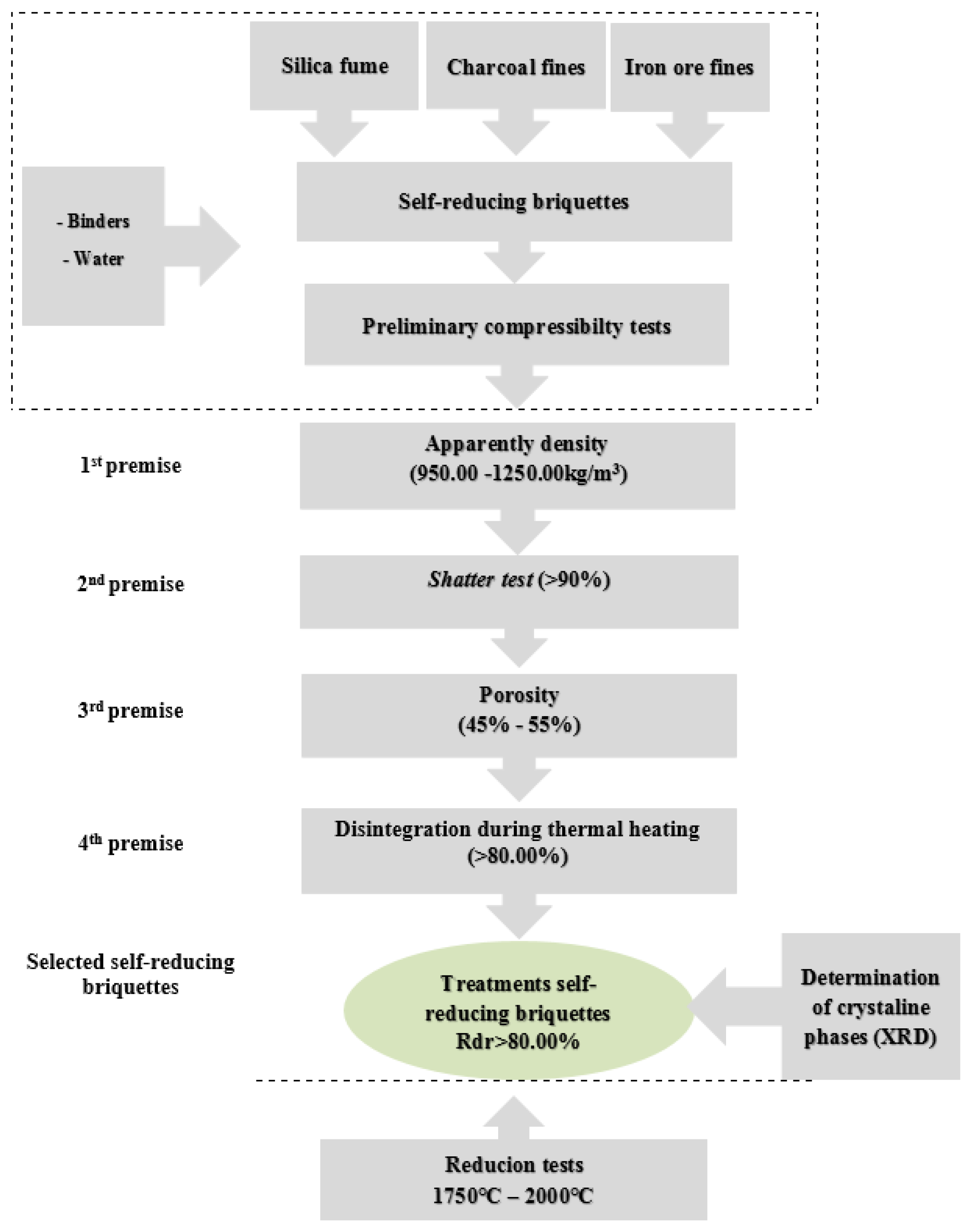
2. Materials and Methods

2.1. Sampling and Sample Preparation

The waste samples from the FeSi production process which were used as raw materials in the production of the self-reducing briquettes were provided by a FeSi75% industrial producer, located in the State of Minas Gerais in Brazil. Samples were collected from wastes provided by this metallurgic plant using standard ABNT NBR 10004:2004 [23]. The size distribution of the fines was <3.00 mm. The waste samples were chosen for the sampling by the method of quarters in conical piles, until fractions for characterization and production of briquettes were obtained.

2.2. Sample Characterization of Wastes and Composition of Self-Reducing Briquettes

For the characterization of the waste fines, granulometric analyses were performed of dry samples of iron ore and charcoal fines. By using a sieving technique, the fines passed through a series of sieves with 3.35 mm, 2.00 mm, 1.00 mm, 0.50 mm, 0.25 mm, 0.15 mm, 0.075 mm and 0.038 mm opening. The granulometric characterization of the silica fume was carried out using dry samples and it was analysed by the laser diffraction technique (Mastersizer 3000, Malvern Panalytical, Malvern, UK).
Then, chemical analyses were done using the inductively coupled plasma spectrometry technique (ICP-OES, Perking Elmer Optima, 7300 DV). Determination of moisture, loss by calcination (PPC) and immediate analysis (content of moisture, volatiles, ash, and fixed carbon) in the charcoal fines were performed.
The formulation for the self-reducing briquettes was determined by the stoichiometric calculations of the simplified mass balance to produce 1 ton of FeSi75. Effectively, to know the amount of raw material needed to produce 1 ton of FeSi75, it is necessary to know the chemical composition of the raw materials and the alloy to be produced. In this perspective, as described in literature [9,15,16], to produce FeSi alloys, the control of the mixtures should be performed in a quantitative (amount of carbon introduced in the carbon/quartz ratio) and qualitative way (quartz nature, reactivity, particle size distribution of the raw materials, and porosity of the charge).
The production of self-reducing briquettes reported in this work aims to use a high fraction of silica fume in the mixture of the briquettes, increasing its reactivity, and reducing waste in the production process. The silica fume will replace the quartz as the raw material, supplying SiO2 for the self-reducing briquettes. The percentage composition of waste to produce self-reducing briquettes is described in Table 1.
Binders were added to the mixture when necessary. These were discounted in the proportion of silica fume and when necessary, the addition was in the proportion of charcoal used in the mixture.
Three types of binders were used in the briquettes: Portland cement, hydrated lime, and sodium silicate. In addition, mixtures without binders were prepared. The addition of binders was considered necessary, so was initially performed with variations that occurred in the proportions of 0.00%; 2.50%; 5.00%; 7.50% and 10.00% based on studies related to the works [17,18,19,21,24].
In total, 13 different mixtures were prepared using silica fume, iron ore fines, charcoal fines, and binders, as shown in Table 2. To organize the various samples, they were labelled M1 through 13, where M stands for mixture, and the following number indicates the type of mixture. Four moisture levels were used for testing: 0.00%, 5.00%, 10.00% and 15.00%. When water was added to the mixtures, the briquettes were produced and labelled with the letters BM. As such, adding in the acronym BM, the numbering of the respective mixture from 1 to 13, and then the digit (−), the letter A representing the water and its addition percentage in numbering from 1 to 4, with the number 1 for 0.00%, the number 2 for 5.00%, the number 3 for 10.00% and the number 4 for 15.00%, representing the percentage of water added in the respective mixture, the labelling was completed. Thus, 52 treatments were investigated.
The mixtures were submitted to briquetting in a hydraulic press (with a maximum capacity of 10 t), using a cylindrical matrix and a compression piston. Approximately 30.00 g of each mix was inserted and placed inside the cylindrical matrix. The pressure of compaction, 5.00 t (77.52 MPa) was defined in preliminary tests of structural evaluation of the self-reducing briquettes. The compaction time was 60 s and the curing time at least 10 days. Five cylindrical briquettes were produced with each mixture in this way. Figure 1 shows an example of the cylindrical briquettes produced.

2.3. Physical Characterization of Self-Reducing Briquettes

The knowledge of the structural resistance behaviour of the self-reducing briquettes was a prerequisite for the selection and eligibility of the briquettes. The structural resistance may also be linked with the kinetic and thermodynamic conditions that would promote the self-reduction [4,20,21,22,23,24,25]. Figure 2 shows the methodological flowchart with the experimentation tests and analyses to which these agglomerates were submitted. The lower range was stipulated for each experimental test and this criterion was considered as a selection filter of the treatments that would be submitted to the subsequent tests.

2.3.1. Apparent Density

The apparent density was determined for a set of three briquettes for each sample produced, achieving an average between the three series. For the cylindrical briquettes, the apparent density was determined through an association between the mass and volume of each briquette.

2.3.2. Shatter Test (Adapted Methodology)

Methods of measuring the shatter resistance of self-reducing briquettes are described in ASTM D440:2002 [26], ISO 616:1995 [27] and JIS M8711:2011 [28]. Adhering to the described methodologies, the impact strength test consisted basically in submitting the briquettes to successive falls from a preliminary height of 0.30 m. Only the briquettes that obtained shatter resistance above 90% for the initial test were considered suitable for the sequence of tests involving falling from a height of 1.50 m.
The shatter tests simulated a similar fall of the raw materials from the conveyor belt to the surface in the SAFs. The shatter index was obtained by a series of five repetitions, for the 52 types of produced treatments, where the average was calculated. The resulting shatter index was the percentage in mass of the fraction passing 9.50 mm that was defined as the index of fines generation by slump. Being the percentage in mass of the passing fraction of the briquette (M1), in relation to the total mass of the sample of briquette tested (M). Equation (2) shows the calculation of the breakage index and Equation (3) the calculation for the determination of the shatter resistance (R):
shatter index :   M 1 M   ×   100
R: 100 − (%)shatter index

2.3.3. Porosity

The porosity analyses were performed on the treatments of self-reducing briquettes that obtained results equal to or higher than 90% in the drop resistance tests (1.50 m). The porosity is an important parameter in the determination of the physical resistance and the electrical resistivity; thus, to reach the necessary resistivity (0.13 Ω/m) at 1200 °C, for the use of the aggregate in electric arc furnaces, the adequate porosity is 45–55% [4]. For the analysis procedure, the gas pycnometry technique [Ultrapyc, model 5000, Anton Paar] was employed by injecting the inert gas (helium) to be absorbed on the surface of the samples. Equation (4) shows the calculation to determine the porosity of the self-reducing briquettes, where Vg: represents the geometric volume (g/cm3) and Vp: pycnometer volume (g/cm3):
Porosity : V g V p V g × 100

2.3.4. Disintegration during Thermal Heating

The influence of temperature on the structural integrity of the self-reducing briquettes was analysed in those treatments that met the criteria of porosity between 45–55%. The proposed tests evaluated the physical characteristics of resistance to high temperature of briquettes, in a non-standardized test [29]. The procedures for quantification of this test were based on the ISO 8371:2015 [30] and ISO 7215:2015 [31] standards. For iron ore pellets for use in reduction reactors, the crackling index test is one of the main evaluations of the metallurgical characteristics of this ore. The tests were performed in a muffle furnace, with temperature variation from 0 °C to 1200 °C in 300 °C increments. The briquettes were weighed, before and after the preheating treatment, and then sieved in a granule sieve with a 9.50 mm mesh. The resistance to thermal heating was determined as the percentage material retained in the sieve, and this size mesh was taken as a reference because it is the minimum grain size for raw material in electric arc furnaces. Equation (5) shows the calculation used for determination of the resistance to degradation (Rdr) against the thermal gradient applied to the treatments of self-reducing briquettes M1. The mass of the material retained in mesh of 9.50 mm (g) and M the mass of the initial agglomerate (g):
R d r : M 1 M × 100
Thus, only the self-reducing briquette treatments that presented Rdr values >80% [4,32,33] were selected for evaluation of their reduction.

2.3.5. Determination of Crystalline Phases by X-ray Diffraction (XRD)

The samples of the treatments that obtained the value of Rdr >80% were submitted to the qualitative analyses by X-ray diffractometry (XRD) [Philips PANanalytical, model PW1710, UFMG]. CuKalpha radiation and monochromator in 0.06° (2θ) step were used, at 40 kV and 40 mA. The analysis method was based on the comparison of the values of interplanar distances and peak intensities in the diffractograms of the samples analysed, and a reference sample, using the standard PDF-2 Release 2010 database of the ICDD—International Centre for Diffraction Data and the software X’Pert HighScore PLUS version 4.0 (Almelo, The Netherlands).

2.4. Metallurgical Characterization of Self-Reducing Briquettes

The evaluations of the metallurgical behaviour are determining factors for the investigation of the metallic and carbonaceous phases of the self-reducing briquettes as a function of the experimental temperatures, as well as their self-reducing character. The criteria adopted as pre-established conditions for the selection of the treatments of the self-reducing briquettes conforms with the premises established for selection of the load in the SAF. Thus, to verify the reduction of the briquettes, they were subjected to reduction tests at different temperatures (Table 3). Subsequently, the remaining materials from these tests were analysed in SEM/EDS, to determine their composition and the individual phases presented.

2.4.1. Reduction-Fusion Tests

The selected self-reducing briquettes were submitted to different temperatures to verify their self-reduction. These tests were intended to simulate the intermediate and lower zones of the SAF during production of ferroalloys and metallic Si. According to [4,7,15,34,35,36] the fusion tests aim to evaluate the composition of the products obtained in the process by investigating the final alloy. Thus, a graphite tube furnace with a maximum operating temperature of 2000 °C ± 10 °C was used at the Norwegian University of Science and Technology (NTNU). The equipment is divided into two parts: (a) the SiO-condensation chamber, located in the upper part, and (b) the high temperature chamber, in the lower part, similar to the schematic described in [34].
The atmosphere inside the furnace was homogenized by purging by helium gas (He) before starting the experiments and the pressure was reduced to 0.18 mmHg. The inert gas was used in a flow rate of 0.10 L/min at 1 atm. The briquettes that met the requirements stipulated in the experimental procedure described in Figure 2 were then heated in a graphite crucible at temperatures specified in Table 3.
A preliminary test to investigate the behaviour of self-reducing briquettes was carried out. A sample with a mass of 24.65 g was held at 2000 °C for 30 min. The intention was to verify how much of the mass of the briquette would be consumed and thus, to measure the remaining material. This would help establish a methodology for the experiments as regards to target temperatures and exposure times. After the exploratory test, only 4.50 g of the sample remained, as shown in Figure 3a,b.

2.4.2. Scanning Electron Microscopy (SEM) and Semi-Quantitative Analyses by Energy Dispersive X-ray Spectroscopy (EDS)

After cooling to room temperature, the remaining material was removed from the graphite crucible, and image analyses were carried out in an ULTRA 55 microscope (Zeiss, NTNU, Trondheim, Norway).
Through the results obtained in semiquantitative analysis of SEM/EDS it is possible to determine the composition of the individual phases present; metallic, carbonaceous or slag. By confronting the results of mass or atomic composition of Si of the metallic phases obtained by EDS analysis, it would be possible to relate them to the information provided by the Fe-Si diagram, and thus confirm the presence of the respective metallic phase (Si; FeSi and FeSi2).

3. Results and Discussion

3.1. Sample Characterization of Wastes

Table 4 shows the size distribution, percentage of passing material (10, 50 and 90%) and the diameter (μm) of the amorphous silica fume particles, in accordance with the results reported in several works [6,7,8].
Figure 4 shows the particle size distribution curve with the accumulated throughput of the waste (ore fines and charcoal) in the form in which they were donated to produce self-reducing briquettes. For both the fines of iron ore and of charcoal, it can be seen that they are predominantly composed of fine particles. Approximately 50% (D50) of the charcoal fines particles have sizes below 0.50 mm and the iron ore fines 0.20 mm, but 90% (D90) of the particles for both samples have sizes below 2.00 mm.
However, in general, the curve of the charcoal fines has fewer fines compared to the iron ore fines. It was expected that the ultrafine and fine particles of the silica fume together with the fine particles of the charcoal and the iron ore would agglomerate quite homogeneously so that the voids could be filled efficiently. As finer particles are preferred for briquetting [37], pressure agglomeration is a prospective alternative process to agglomerate fines [38].
The results of the elemental analyses of the silica fume, iron ore fines and charcoal chips are described in Table 5, which shows the average values of the chemical analyses of the waste used to produce the self-reducing briquettes.
As shown in Table 5, the silica fume presented a chemical composition typical of that found in ferrosilicon metallurgical industries. This is similar to the results described in several scientific works [4,6,12]. It can, however, be noted that the K2O content is quite high. On the other hand, the chemical composition of the charcoal fines presented higher values of SiO2 than the chemical composition of the charcoal described in the literature [13]. The iron ore fines have a chemical composition with a lower percentage of iron oxide than that the scientific literature stipulates is needed to produce FeSi [13,39], and contain high silica content compared to the published chemical composition of the iron ore [3]. The analysis of the charcoal fines is presented in Table 6, which shows the percentage of moisture (water content of the material), ash (residual material after combustion), volatile materials (the content of material that is burned in the gaseous state) and fixed carbon (the content of material that is burned in the solid state). Based on the results described in Table 5, the components of the charcoal fines presented compatibility with similar analyses generated in the screening process of metallurgical and or steel mills [40]. Compared to the charcoal bulk material, the ash content in the fines is much higher.

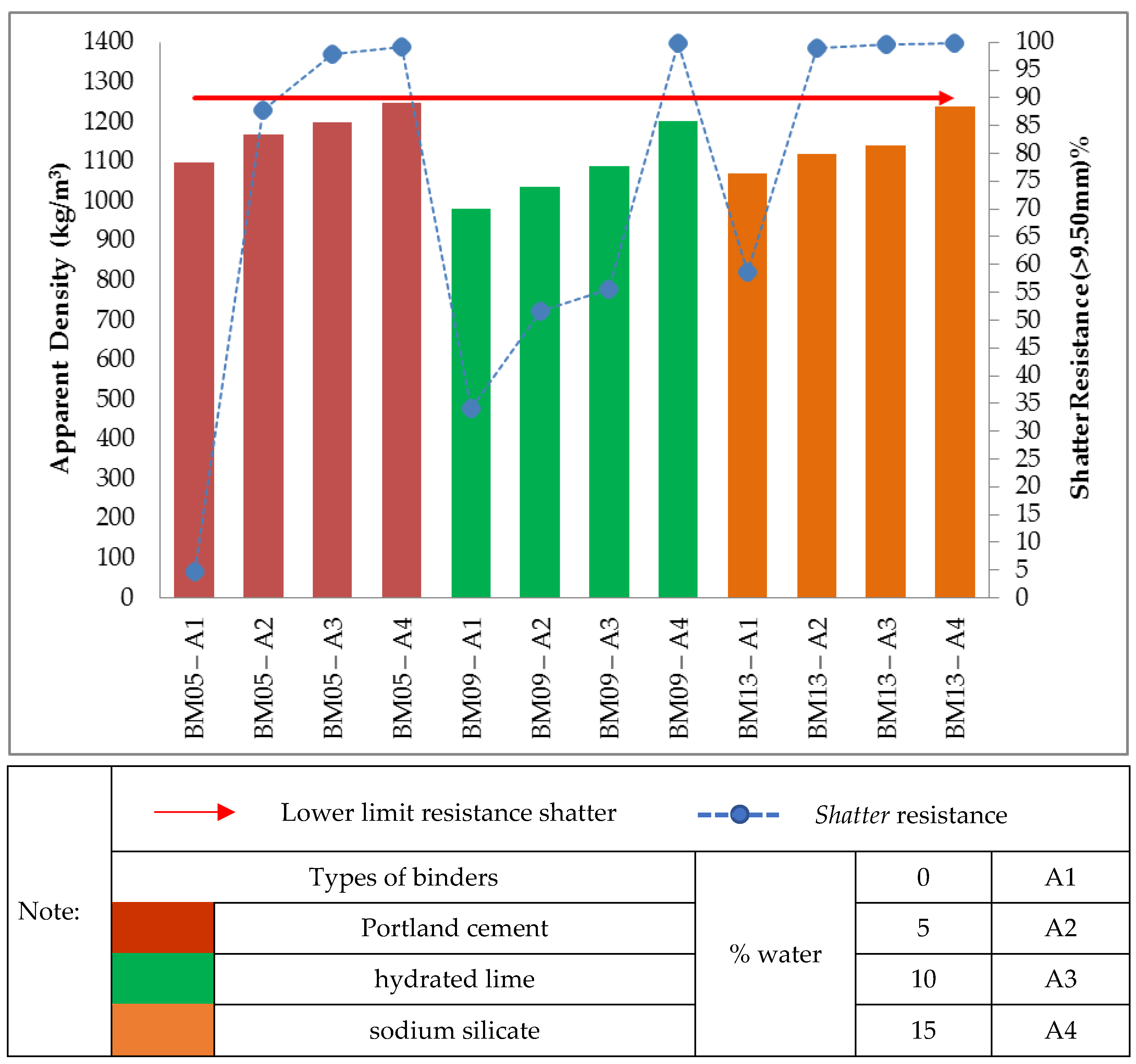
3.2. Apparent Density and Shatter Test in Briquettes

Figure 5a shows the self-reducing briquettes without binders (BM01). It is evident that these only obtained stipulated shatter resistance when the additions of water were 5.00%, 10.00% and 15.00% (R > 90%). This confirms that the greater the surface area and the lower the packing density, the greater the water demand will be. It is also important to note the effect that the amount of water exerted on the mechanical strength of self-reducing briquettes, even in those without binder addition. The added water possesses, due to its capillarity effect, the tendency to agglomerate the raw materials and confers initial resistance essential to its modelling [41].
Figure 5b shows the relationship between the apparent density and strength of briquettes with binders in the proportions of 2.50% for different types of binders, Portland cement, sodium silicate and hydrated lime. As presented, the apparent density for all treatments with a proportion of 2.50% binders obtained apparent density values within the stipulated range (950.00 kg/m3–1250.00 kg/m3). It was also found that the results obtained for the drop strength (0.30 m) were increasing in relation to the apparent density values in most treatments.
However, it was observed that the treatments with Portland cement binder obtained the highest values of apparent density (1070.97 kg/m3; 1170.08 kg/m3; 1226.68 kg/m3 and 1245.38 kg/m3) and minor variations for the results obtained for shatter resistance (0.30 m), although only two treatments (BM02-A3 and BM02-A4) obtained the shatter resistance index above the stipulated value (R > 90%).
On the other hand, the treatments with hydrated lime binder obtained the lowest values of apparent density (985.64 kg/m3; 1041.48 kg/m3; 1054.79 kg/m3; 1118.22 kg/m3) and greater variability for the obtained results of shatter resistance (0.30m), in which only 1 treatment (BM06-A4) obtained a value for the shatter resistance index above the stipulated R = 99.18%.
The treatments with sodium silicate obtained apparent density results between the values obtained (1017.01 kg/m3; 1099.68 kg/m3; 1187.05 kg/m3; 1217.47kg/m3) It is noteworthy that the highest obtained value of shatter resistance (0.30 m) comprised the treatment BM10-A4, R = 99.27%.
Figure 6 shows the relationship between the apparent density and strength of briquettes with binders at proportions of 5.00% for the different types of binders, Portland cement, sodium silicate and hydrated lime. The apparent density for all the treatments with binder proportion 5.00% obtained values within the stipulated density range (950.00–1250.00 kg/m3). Consequently, the results obtained for the shatter resistance (0.30 m) were increasing in relation to the apparent density values. It was noticed that all treatments obtained very close values of apparent density; with Portland cement binder (1059.32 kg/m3; 1113.40 kg/m3; 1128.86 kg/m3 and 1188.45 kg/m3), with hydrated lime binder (1013.66 kg/m3; 1028.08 kg/m3; 1074.3 kg/m3 and 1146.96 kg/m3), and with sodium silicate binder (1059.76 kg/m3; 1072.66 kg/m3; 1120.01 kg/m3 and 1165.39 kg/m3). In general, only two treatments with Portland cement binder (BM03-A3 and BM03-A4); one treatment with hydrated lime binder (BM07-A4) and two treatments with sodium silicate binder (BM011-A3 and BM11-A4) obtained the shatter resistance index above the stipulated value (R > 90%).
Figure 7 shows the relationship between apparent density and briquette strength with binders in the proportions of 7.50% for different types of binders, Portland cement, sodium silicate and hydrated lime. The treatments of self-reducing briquettes made with the three types of binders, with proportion of 7.50%, also obtained apparent density within the stipulated range (950.00 kg/m3–1250.00 kg/m3). However, regarding the shatter resistance, only two treatments made with Portland cement binder (BM04-A3 and BM04-A4), one treatment with hydrated lime binder (BM08-A4) and two treatments with sodium silicate binder (BM012-A3 and BM12-A4) obtained the shatter resistance index above the stipulated value (R > 90%).
Finally, Figure 8 shows that the treatments of self-reducing briquettes with the three types of binders with a proportion of 10.00% also obtained apparent density within the stipulated range (950.00–1250.00 kg/m3). On the other hand, regarding the shatter resistance only two treatments made with Portland cement binder (BM05-A3 and BM05-A4), one treatment with hydrated lime binder (BM09-A4) and three treatments with sodium silicate binder (BM012-A2; BM012-A3 and BM12-A4) obtained a shatter resistance index above the stipulated value (R > 90%).
Thus, as shown in Figure 5, Figure 6, Figure 7 and Figure 8, of the 52 treatments of self-reducing briquettes tested for impact strength in a 0.30 m drop only 23 reached R > 90%.
The high impact strength of self-reducing briquettes using Portland cement as a binder was confirmed. According to the literature [42], when water is mixed with cement, various compounds are formed, including calcium silicate hydrate (C-S-H) and calcium hydroxide (C-H). In addition, by adding silica fume along with Portland cement, a reaction with (C-H) occurs, producing more (C-S-H), further increasing the mechanical strength of the mixture, and the ratio for inserting silica fume into cement mixtures is 15% to 20%. However, it is uncertain whether this can occur at these low temperatures.
The present work also explored the production of self-reducing briquettes using silica as the main component and the potential use of Portland cement as a binder. Furthermore, as certain variations in the mass of silica fume, binder and water proportions have already been investigated [43], an attempt was made to evaluate the variations in the mechanical strength of the mixture in accordance with the performed research.
In contrast, it is notable that the self-reducing briquettes made with hydrated lime binder (BM06; BM07; BM08 and BM09) only obtained the stipulated impact strength >90.00% when the maximum proportion of water, 15.00%, was used. Smaller proportions of water (0.00%; 5.00% and 10.00%) obtained unsatisfactory results, since the degradation of the materials was greater than 10%. These results were already expected, considering that mixtures containing hydrated lime as a binder already presented low strength and fragility, even during compaction.
Previous research [22] produced briquettes from coal fines and different types of organic, inorganic, and combined binders; the following basic mixture (% dry matter) was assumed: coal fines-90, bio-mass-6 and binder-4. Thus, when using virgin lime or hydrated lime, the briquettes prepared with this type of binder did not show satisfactory results, causing deterioration both in compaction and later showing mechanical strength well below the assumed minimum (R = 85%). Regarding the study of [44], when investigating lignite agglomeration, they found that the cohesive properties of lime are not strong for some types of materials and that the proportion of lime should be between 25–30% when used as a single binder.
To conclude: when analysing the performance of the briquettes made with sodium silicate binder, they showed adequate mechanical strength for the following treatments: BM10—2.50% binder and 15.00% water; BM11—5.00% binder and when added 10.00% and 15.00% water; BM12—7.50% and when added 10.00% and 15.00% water; and BM13—10.00% binder and when added 5.00%, 10.00% and 15.00% water.
This is in accordance with the literature [24] that described the mechanisms of briquetting in rotary kilns (RHF). In the cited work, the briquettes were produced with blast furnace dust and used sodium silicate as a binder. The results show that the oxygen and silicon bonds produced between the acidic silica gel particles from the curing reaction influence the negative ion connection bridge, linking the gel partitions and the sodium carbonate particles into a complex network structure.
The presence of liquids as free moisture between the particles, especially in a wet agglomeration process, causes cohesive forces between the particles, as the thin adsorption layers (≥3.00 nm thick) are immobile. They can form strong bonds between adjacent particles, smoothing the surface roughness and increasing the contact area between the partitions or decreasing the distance between the particles and allowing intermolecular attraction forces to participate in the bonding mechanism [45].
It is noteworthy that for all briquettes, the increase in apparent density of the briquettes resulted in gains in shatter resistance, generating an inversely proportional amount in mass of fines (Figure 9). Evidently, it is because higher densities provide a better packing and a more effective contact between the particles, reducing the empty spaces, which increases the resistance of the agglomerates.
As the proportion of silica fume in the mixture increased, the tendency is a decrease in apparent density followed also by a decrease in the resistance of the briquettes. In relation to the different water additions, humidity provided a cohesive force necessary for the adherence of the particles to be agglomerated. This force also depends on the capacity of water adsorption by the particles, thus helping in the mechanical resistance. As shown in Figure 9, of the 23 treatments of self-reducing briquettes tested for impact strength in a 1.50 m drop, only 12 reached R > 90%.

3.3. Porosity in Self-Reducing Briquettes

The average porosity values are presented in Figure 10, respectively the twelve treatments of self-reducing briquettes tested for porosity determination. Of the twelve treatments of self-reducing briquettes that were analysed in the porosity determination tests, only ten met the premise of adequate porosity (45.00–55.00%), a parameter established to ensure that carbon monoxide formed in the furnace has access to the components of the pellets [4].
It was observed in the self-reducing briquettes produced with Portland cement that, when there was an increase in the percentage of binder, a decrease in porosity resulted. Thus, it was found that the porosity of the briquettes depends on both the water/binder ratio and the degree of hydration of the mixture. For the results in the case of cement content, the H/C and S/C ratios increase in C-S-H, a component that promotes greater strength to the mixture. Furthermore, the increase in moisture allows a greater formation of Ca(OH)2, which results in a decrease of C in the C-S-H gel, therefore resulting in an increase in the S/C ratio and promoting the formation of a more compact composite with reduced porosity [46].
Briquettes produced with sodium silicate binder also showed a de-creasing value of porosity in relation to the increase in the percentage of binder. This shows that the gel particles penetrate into the briquettes, block the capillary pores, and the connection between the component particles of the briquette is reinforced by the silica acid gel particles. Therefore, increasing the binder content will decrease the number and size of the pores [24].
Furthermore, the only self-reduced briquette treatment produced with water satisfied the stipulated porosity premise. The same was true for the only treatment produced with hydrated lime. This corroborates the important relationship between the composition of water and binders [47].
After analysis and evaluation of the porosities of the self-reducing briquettes, the treatments that met the values within the stipulated range were forwarded for disintegration during thermal heating.

3.4. Disintegration during Thermal Heating

Figure 11 shows the average values of three repetitions of the resistance against thermal heating in relation to the temperature levels of 300 °C, 600 °C, 900 °C and 1200 °C. The goal for the thermal heating was to obtain a Rdr > 80%.
The resistance to thermal degradation and determination of the value of Rdr = 80% for the briquettes produced with the composition of waste electrofilter were also evaluated in the literature [4,33] and their average value of Rdr was equal to 82.50%. These briquettes were produced with 23.00–27.00% silica fume, 51.00–53.00% carbon reducing agent, 4.00–5.00% silicon fines and 14.00–15.00% sodium silicate binder. In relation to the self-reducing briquettes of this present work, it was noticed that from 600 °C the resistance of some treatments of self-reducing briquettes produced with Portland cement reduced drastically for the studied levels. It is noteworthy that in the production of briquettes with Portland cement, none obtained Rdr > 80%. This is in accordance with study [46], in which it was found that the loss of strength related to the combined effect of the destruction of the binding phase (C-S-H) and the beginning of phase transformations of iron oxides. Sequentially, the treatment BM 08-A4 with addition of hydrated lime as binder showed resistance to thermal degradation with Rdr less than 45.00%, confirming published research [21,48].
It was noted that for the briquette samples without binders (from 600 °C), the Rdr was <80% and was not stipulated to meet the premise of resistance to thermal heating. However, in relation to the briquette samples without binders, BM01-A4, their resistance behaviour against thermal heating (Rdr = 57.65%) was higher than some of the samples that had Portland cement as binder (BM02-A4; BM03-A3 and BM05-A4).
The self-reducing briquettes with sodium silicate binder showed satisfactory results in which two samples (BM11-A4 and BM12-A4) met the premise established for defined selection, as demonstrated in Figure 11. The connections between sodium silicate and the constituent particles occur approximately at 1000 °C, thus at a higher temperature than the other agglomerants studied [24]. This is in accordance with the analysis of the influence of sodium silicate in pellets of chromite and carbon fines [49], in which the binder added in briquettes of 4.00% with room curing presented the best performance even after exposure to high temperatures of 900 °C (1173K) to 1100 °C (1373K).
Finally, the hot mechanical resistance decreased at each elevation of the stipulated temperature levels and the respective exposure time to the thermal gradient. This occurrence is related to the breakage of bonds of binders and particles of the self-reducing briquettes, in addition to the output of the volatiles of the fine charcoal because in this atmosphere (air), part of the coal goes into combustion, which would not occur in an industrial oven. It was observed that the variations of types and proportions of binders, the proportion of water and composition of self-reducing briquettes are important factors to establish the pattern for the structural stability of self-reducing briquettes [19,24,45,50].
After performing the tests of resistance to degradation against thermal gradient, only two samples (BM11-A4 and BM12-A4) met the stipulated premise (Rdr > 80%). Figure 12 shows the images of the samples produced with sodium silicate binder (B12-A4; BM12-A3 and BM11-A4) after being submitted to the temperatures proposed for the thermal degradation tests.

3.5. Analysis of the Crystalline Phases

The samples (BM11-A4 and BM12-A4) that obtained the value of Rdr > 80% were subjected to qualitative analyses by X-ray diffraction (XRD) and the main crystalline phases present in the raw materials of the self-educated briquettes were identified.
The results obtained by the analyses were consistent with others already reported in the scientific literature, related to iron ore fines, charcoal fines and silica fume [13,14,51].
As shown in Figure 13 and Figure 14 the presence of quartz (SiO2) phases was observed, this predominantly amorphous phase coming from silica fines and charcoal [6,13,14,41]. Hematite phases were also identified relating to iron ore fines, one of the main representatives of iron minerals (Fe2O3) and in higher concentration in Brazilian mineral deposits [29,35,51,52]. On the other hand, the presence of calcite (CaO) phases is predominantly related to charcoal fines [14].
This indicates that the mineral phases that were found are oxides and high temperature furnace processes can reduce these. It is worth noting that the results obtained by XRD analyses corroborate with the content obtained from the chemical analyses performed by ICP, described previously in Table 5.

3.6. Reduction Tests

The loss of mass of the briquettes was an indicator for carbothermal reactions consuming the raw material while generating SiO(g) and CO(g). This means that the increase in temperature promoted greater production of gases and thus led to loss of mass [51]. Figure 15 shows the total mass loss of each treatment of self-reducing briquettes subjected to the reduction tests at high temperature.
The total mass loss was between 58.00 to 82.00% with temperatures increasing from 1750 °C to 2000 °C. Similar results to these were reported by other researchers using agglomerates of quartz fines and SiC; in the temperature range of 1550–1820 °C, the mass loss obtained was 49.3–85.5% [53]. In the experimentation with agglomerates of quartz fines <70µm in reduction tests covering temperatures 1600 °C–1900 °C, it was respectively 55.8–77.7% [53]. On the other hand, agglomerates produced with quartz fines of particle size 0.4 mm and SiC with particles of 0.5mm to 10.0mm, during heating at target temperatures between 1700 °C and 1900 °C, obtained mass loss of 35.61–90.13% [35]. Thus, it was possible to verify that the results found are in consistency with the inherent mass loss of the raw materials during the processing and production of the metallic alloy [10,53,54,55]. The cold load inside the SAF captures the SiO-gas. A sufficient reduction in the viscosity of the molten SiO2 at 1750 °C is observed together with a rapid loss of mass, possibly related to the increase of the reaction rate. The melting temperature of pure silica is 1720 °C, although softening and melting temperatures for different industrial quartz varieties vary between 1600 °C and 1800 °C [9,14].

Phase Distribution

At the temperatures of the reduction tests, all the metal was in the form of a Fe-Si liquid solution and when cooled after the experiments, it solidified into FeSi-FeSi2 or FeSi2-Si, depending on the amount of Si in the liquid solution. Thus, by checking how much Si, FeSi and FeSi2 that occurs in metallic phase, one can determine the composition of the metal [56]. The metallographic analysis in SEM/EDS determined the composition of the individual phases present: metallic, carbonaceous and slag in the two treatments of self-reducing briquettes (BM11-A4 and BM12-A4) that were submitted to reduction. Confronting the results of mass or atomic composition of Si, of the metallic phases obtained by the EDS analyses, it is possible to relate them to the information provided by the Fe-Si diagram.
In accordance with the Fe-Si phase diagram [39], any Fe-Si alloy must contain more than 58.2% by mass of silicon to form silicon crystals during equilibrium solidification above the eutectic temperature.
The investigation of the original phases (SiO2, FeOx, C) as well as of the formed phases is of extreme importance for determination of the viability of insertion of the self-reducing briquettes as complementary load for the SAF. The formed phases will be SiC, FeSi with variable composition of Fe to Si, and the generation of slag of FeO, SiO2 and oxides originating from the agglomerate. SiC and FeSi are interesting components in a self-reducing briquette [54].
Figure 16 shows cross-section views of a sheet containing metallic Si and FeSi2 phases and formation of the carbonaceous SiC phase after reaction at 1800 °C for 30 min of the BM11-A4 treatment. Along the whole SiC/graphite interface, metallic particles of micron size were found. It is noteworthy that, as shown in Figure 16a,b there was a prevalence of SiC phase formation in all visible phases. Figure 16c shows metallic incrustations and slag. Figure 16d shows the condensation of SiO gas, at 1800 °C, at the graphite/SiC interface on the top of the crucible. SiO-gas is one of the reaction products of the silica at high temperature. It was observed that the SiO gas from the self-reducing briquettes reacted with the C(s) in the crucible and produced some carbonaceous phase granules of SiC(s) embedded in the crucible. This indicates that some of the silicon left the experimental system as SiO gas; as shown in Equations (6)–(8):
SiO2(s) + C(s) = SiO(g) + CO(g)
SiO2(s) + 2C(s) = SiC(s) + CO(g)
SiO(g) + 2C(s) = SiC(s) + CO(g)
Slag formation containing predominantly CaO-SiO2 (32.55–76.27%) was also observed, the optimum values in slag composition for silicon production being 75% in the metal phase, with composition 29.1 % Al2O3, 25.9 % CaO and 45 % SiO2 [16].
Figure 17 shows a cross-section of the BM11-A4 treatment under a temperature of 1850 °C for 30 min. The amount of carbon present in the FeSi2 phases is smaller in comparison to the chemical composition at a temperature of 1800 °C, which suggests that the increase in temperature favours the carbo-chemical reactions inherent to the FeSi production process, with the gradual evolution of the C(s) consumption reactions (7, 16, 55). Two mechanisms of Si production have been observed: transpiration of Si metal from the condensate layer around the crucible and production of Si in SiC particles [56,57]. Figure 17a,b, shows the presence of metal droplets containing Si phases, FeSi2 and those containing SiC incrustations. Figure 17c shows that there was formation of the metallic phase of FeSi2, but also SiC particles containing high contents of SiO2, CaO-Al2O3. Although the FeSi production process is considered to be a slag-free process due to the high purity of the raw materials, there is still slag formation. The most abundant oxide impurities are the aluminium (Al2O3) and calcium (CaO) oxides that form a phase together with SiO2, to form an Al2O3-CaO-SiO2 system [9,16,58]. Figure 17d shows the image of the crucible bottom containing slag and SiC, with demonstration of the metallic pockets formed on the SiC and slag/graphite interface.
Figure 18 shows a cross-section of the BM11-A4 treatment at 2000 °C for 30 min, in which metallic and SiC phases were found. Especially at 2000 °C, the formation of metallic droplets with phase composition in the FeSi2-FeSi area can be observed (Figure 18a,b) which demonstrates that metal formation occurred below FeSi 50% [59]. The presence of SiC(s) presented a lower proportion in the Si/SiC ratio, having a less porous and more consolidated characteristic, besides having higher carbon contents (%) than at the temperatures previously investigated. At 2000 °C the SiC particle is much denser, and the original carbon structure no longer exists in the samples. SiC was found on the surface of FeSi heated at 2000 °C; however, it presented in lower proportions in the Si/SiC ratio than at the lower temperatures (1800 and 1850 °C) investigated previously. The reason for this is not fully understood, but one explanation may be that SiC is formed on the silicon surface particles/droplets at low temperatures due to the presence of small amounts of CO and that SiC reacts with silica at higher temperature [60,61,62]. What is suggested is that the increase in temperature led to the carbo-chemical reactions inherent to the FeSi production process, with the gradual evolution of the C(s) consumption reactions [10,16,54].
Figure 19 shows the products obtained after reduction of treatment BM12-A4 It is worth noting that there was formation of the FeSi metallic phase at 1750 °C for the BM12-A4 treatment (Figure 19a,b), which was not observed at 1800° for the BM11-A4 treatment (Figure 16).
Comparing the treatment BM12-A4 (Figure 19c,d) with the phases of the treatment BM11-A4 (Figure 17), both at a temperature of 1850 °C, the phases produced were similar. In fact, when comparing the results obtained for the FeSi and FeSi2 phases, there were no strong variations in the Si, C and Fe contents. However, on the other hand, it was observed that in the slag produced in both treatments the percentage of CaO present was 30.18% for BM 11-A4 and 5.05% for the BM12-A4 treatment, which may be related to the lower proportion of 2.50% of active silica in the BM12-A4 treatment.
It is worth noting that the values obtained by calculating the equation of reactions and the mass balance applied for this research do not seem to fit the 75% FeSi production, due to the larger amount of SiC that can be seen in the micrographs generated by SEM. Thus, when the calculations are based on a Si content of 60% in the alloy to produce 75% FeSi, the theoretical amount of SiC produced would be around 1.90 g for treatment BM11-A4 and 2.70 g for treatment BM12-A4 respectively a percentage of 7.60 and 10.72% for the total mass of the treatments studied. Thus, if the average Si in the metal was assumed to be 50%, the percentage values would better represent the results of the products obtained. Thus, the theoretical amount of SiC produced would be around 4.10 g for treatment BM11-A4 and 4.90g for treatment BM12-A4, respectively; a percentage of 16.40% and 19.60% for the total mass of the researched treatments.
Finally, it is assumed that this occurrence is due to the heterogeneity of the raw materials, which are wastes, which may also describe the deviation, i.e., the actual analyses would not be the average analyses assumed for the self-reducing briquettes produced.

4. Conclusions

It was concluded that the thirteen types of mixtures studied presented adequate briquetability, but the variations of binder and water percentage affected structural behaviour and process operability. There was an increase in the apparent density in relation to the elevation of the water/binder proportion of the mixture for all the self-reducing briquettes produced. It was also noted that with the increase in the proportion of binders—Portland cement and sodium silicate—there was a decrease in the porosity. In relation, the resistance to hot thermal degradation was decreasing with each increase in the temperature/time of exposure to thermal gradient, with this characteristic being observed in all types of self-reducing briquettes submitted to these tests. Consequently, only two of the produced treatments BM11-A4 (5.00%) and BM12-A4 (7.50%), both with addition of sodium silicate binder, showed Rdr > 80%.
As for the reduction tests, it was shown that the steps of the FeSi process can be simulated in a small-scale induction furnace, even using only self-reducing briquettes. The formation of metallic Si particles was evident from 1750 °C onwards. At temperatures from 1800 °C to 1850 °C, the analysed metal had 50/50 Si-FeSi2 phases, i.e., FeSi75. However, some metal nodules are found in the area with FeSi-FeSi2 phases, below 50% FeSi, especially at 2000 °C. In addition, it was observed that Si was also condensed as SiO gas, which can be seen at the top of the carbon crucible, and this was partially transformed into SiC. In addition, no SiO2 was found except as CaO-Al2O3-MgO-SiO2 slag.
Additionally, the relative percentage error with respect to the introduction of silicates and the carbonaceous material into these agglomerates was calculated. Thus, describing a relative error of 4.26% for the BM11-A4 treatment and 4.50% for BM12-A4 for the silica fumes, the results were present as if there was a smaller amount than reported. On the other hand, the fines for the charcoal showed results as if there was a greater amount of carbonaceous material than reported in both treatments, showing a relative error of 5.88%.
Thus, it is understood that the introduction of self-reducing briquettes as a possible complementary load could represent a viable and advantageous alternative, being used in the production of FeSi types that have wider specification limits.
This work added significant and unpublished data, which can contribute positively in relation to the properties presented by self-reducing briquettes with the respective wastes from the FeSi industrial segment, but pointing out the need for further research in order to optimize its metallurgical processing, aiming at sustainable development that is a necessary commitment to the industrial sectors and that is certainly correlated with the ore extraction enterprise and its metallurgical processing.

Author Contributions

Conceptualization, A.d.L.P.; methodology, A.d.L.P. and H.A.V.R.; validation, A.d.L.P., M.T. and A.B.H.; formal analysis, M.T. and A.B.H.; investigation, A.d.L.P. and H.K.; resources, A.d.L.P., H.A.V.R. and M.T.; software, A.d.L.P.; data curation, A.d.L.P. and M.T.; writing—original draft preparation, A.d.L.P.; writing—review and editing, M.T., H.A.V.R. and A.d.L.P.; visualization, A.d.L.P., H.A.V.R., M.T. and A.B.H.; supervision, M.T. and A.B.H.; project administration, A.d.L.P. and M.T., funding acquisition, M.T. All authors have read and agreed to the published version of the manuscript.

Funding

Funding for this project from Controlled Tapping (267621) and the SFI Metal production (237768) funded by the Norwegian Research Council.

Institutional Review Board Statement

Not applicable.

Informed Consent Statement

Not applicable.

Data Availability Statement

The data presented in this study are available on request from the corresponding author.

Acknowledgments

The authors would like to thank Mika Serna Malmer for SEM experiments.

Conflicts of Interest

The authors declare no conflict of interest.

Abbreviations

The following abbreviations are used in this manuscript.
ASTM American Society of Testing and Materials
JIS Japanese Industrial Standards
NBR Norma Brasileira Regulamentadora
ISO International Organization for Standardization
NTNU Norwegian University of Science and Technology
SAF Submerged Arc Furnace

References

  1. Willms, T.; Echterhof, T.; Steinlechner, S.; Aula, M.; Abdelrahim, A.; Fabritius, T.; Mombelli, D.; Mapelli, C.; Preiss, S. Investigation on the Chemical and Thermal Behavior of Recycling Agglomerates from EAF by-Products. Appl. Sci. 2020, 10, 8309. [Google Scholar] [CrossRef]
  2. Yap, Z.S.; Khalid, N.H.A.; Haron, Z.; Mohamed, A.; Tahir, M.M.; Hasyim, S.; Saggaff, A. Waste Mineral Wool and Its Opportunities—A Review. Materials 2021, 14, 5777. [Google Scholar] [CrossRef] [PubMed]
  3. Ray, N.; Nayak, D.; Dash, N.; Rath, S.S. Utilization of low-grade banded hematite jasper ores: Recovery of iron values and production of ferrosilicon. Clean Technol. Environ. Policy 2018, 20, 1761–1771. [Google Scholar] [CrossRef]
  4. Nemchinova, N.V.; Mineev, G.G.; Tyutrin, A.A.; Yakovleva, A.A. Utilization of Dust from Silicon Production. Steel Transl. 2017, 47, 948–957. [Google Scholar] [CrossRef]
  5. Lemos, L.R.; Rocha, S.H.F.S.; Castro, L.F.A.; Assunção, G.B.M.; Silva, G.L.R. Mechanical strength of briquettes for use in blast furnaces. REM Int. Eng. J. 2019, 72, 63–69. [Google Scholar] [CrossRef]
  6. Zhdanov, A.V.; Zhuchkov, V.I.; Dashevskii, V.Y.; Leont’Ev, L.I. Problems with waste generation and recycling in the ferroalloys industry. Metallurgist 2015, 58, 1064–1070. [Google Scholar] [CrossRef]
  7. Chashin, G.A.; Kashlev, I.M.; Efimov, G.P.; Bondarev, A.A. Mastering a technology for making a new commercial product—Densified Microsilica. Metallurgist 2009, 53, 233–235. [Google Scholar] [CrossRef]
  8. Kero, I.; Gradahl, S.; Tranell, G. Airborne Emissions from Si/FeSi Production. JOM 2017, 69, 365–380. [Google Scholar] [CrossRef]
  9. Schei, A.; Tuset, J.K.; Tveit, H. Production of High Silicon Alloys; Tapir Forlag: Trondheim, Norway, 1998. [Google Scholar]
  10. Gasic, M. Handbook of Ferro Alloys: Theory and Technology; Elsevier: Cambridge, MA, USA, 2013. [Google Scholar]
  11. Vorob’ev, V.P. Carborundum-Bearing Reducing Agents in High-Silicon Alloy Production. Steel Transl. 2017, 47, 688–690. [Google Scholar] [CrossRef]
  12. Polyakh, O.A.; Rudneva, V.V.; Yakushevich, N.F.; Galevskii, G.V.; Anikin, A.E. Silicon Carbide Production from Steel Plant Wastes. Steel Transl. 2014, 44, 565–572. [Google Scholar] [CrossRef]
  13. Silveira, R.C.; Almeida, A.M.M. Tecnologia da Fabricação das Ligas à Base de Sílicio; Consultoria e Participações LTDA: Belo Horizonte, Brazil, 1988. [Google Scholar]
  14. Aasly, K. Properties and Behavior of Quartz for the Silicon Process. Ph.D. Thesis, Faculty of Engineering Science and Technology Department of Geology and Mineral Resources Engineering, Norwegian University of Science and Technology, Trondheim, Norway, 2008; 236p. [Google Scholar]
  15. Kadkhodabeigi, M.; Tveit, H.; Johansen, S.T. Modelling the Tapping Process in Submerged Arc Furnaces Used in High Silicon Alloys Production. ISIJ Int. 2011, 51, 193–202. [Google Scholar] [CrossRef]
  16. Hustad, H.M. Tapping of FeSi Furnaces. Ph.D. Thesis, Department of Materials Science and Engineering, Norwegian University of Science and Technology, Trondheim, Norway, 2018; 80p. [Google Scholar]
  17. Jia, F. A Kind of Briquette Binder. China Patent CN 101747970A, 23 June 2010. [Google Scholar]
  18. Buzin, P.J.W.K. Desenvolvimento de Briquetes Autorredutores a Partir de Carepas de Processamento Siderúrgico para Utilização em Forno Elétrico a Arco. Master’s Thesis, Programa de Pós-Graduação em Engenharia de Minas, Metalúrgica e de Materiais, Universidade Federal do Rio Grande do Sul, Porto Alegre, Brazil, 2009; 138p. [Google Scholar]
  19. Bizhanov, A.M.; Kurunovb, I.F.; Dashevskii, V.Y.A. Mechanical Strength of Extrusion Briquettes (Brex) for Blast-Furnace and Ferroalloy Production: I. Dependence of the Strength Properties of Extrusion Briquettes on the Binder. Russ. Metall. 2015, 2015, 185–190. [Google Scholar] [CrossRef]
  20. Eremin, A.Y.; Babanin, V.I.; Kozlova, S.Y. Establishing the Requirements for Indices Characterizing the Mechanical Strength of Briquets with Binders. Metallurgist 2003, 47, 437–446. [Google Scholar] [CrossRef]
  21. Zhang, G.; Sun, Y.; Xu, Y. Review of briquette binders and briquetting mechanism. Renew. Sustain. Energy Rev. 2018, 82, 477–487. [Google Scholar] [CrossRef]
  22. Rejdak, M.; Robak, J.; Czardybon, A.; Ignasiak, K.; Fudala, P. Research on the production of composite fuel on the basis of fine-grained coal fractions and biomass—The impact of process parameters and the type of binder on the quality of briquetes produced. Minerals 2020, 10, 31. [Google Scholar]
  23. NBR 10004; Resíduos sólidos—Classificação. Associação Brasileira de Normas Técnicas: Rio de Janeiro, Brasil, 2004; p. 21.
  24. Han, H.; Duan, D.; Yuan, P. Binders and Bonding Mechanism for RHF Briquette Made from Blast Furnace Dust. ISIJ Int. 2014, 54, 1781–1789. [Google Scholar] [CrossRef]
  25. Oliveira, S.J. Avaliação de Briquetes de Misturas de Finos de Minérios de Ferro e Rejeito de Mineração para Uso em altos-Fornos. Master’s Thesis, Programa de Pós-graduação em Engenharia de Materiais. Universidade Federal de Ouro Preto, Ouro Preto, Brazil, 2019; 115p. [Google Scholar]
  26. ASTM D440-86; Standard Test Method of Drop Shatter Test for Coal. American Society for Testing and Materials: West Conshohocken, PA, USA, 2002; 4p.
  27. ISO 616; Coke—Determination of Shatter Indices. International Organization for Standardization: England, UK, 1995; 5p.
  28. JIS M 8711; Test Method for Determination of Shatter Strength of Iron Ore Sinter. Japanese Industrial Standard: Tokyo, Japan, 2011; 4p.
  29. Kumar, M.; Jena, S.; Patel, S.K. Characterization of properties andreduction behavior of iron ores for application in sponge ironmaking. Miner. Processing Extr. Metall. Rev. 2008, 29, 118–129. [Google Scholar] [CrossRef]
  30. ISO 8371; Iron Ores for Blast Furnace Feedstocks—Determination of the Decrepitation Index. International Organization for Standardization: Geneva, Switzerland, 2015; 7p.
  31. ISO 7215; Iron Ores for Blast Furnace Feedstocks—Determination of the Reducibility by the Final Degree of Reduction Index. International Organization for Standardization: Geneva, Switzerland, 2015; 11p.
  32. Swirkowsky, M. Avaliação do Aproveitamento do Resíduo Borra Metálica da Produção de Tubos de aço com Costura para Elaboração de Briquetes Autorredutores. Master’s Thesis, Universidade da Região de Joinville—UNIVILLE, Joinville, Brazil, 2018; 78p. [Google Scholar]
  33. Kulikov, B.P.; Istomin, S.P. Pererabotka Otkhodov Alyuminievogo Proizvodstva (Waste Recycling of Alumnum Industry); LLC “Klassik Tsentr”: Krasnoyarsk, Russia, 2004; 480p. [Google Scholar]
  34. Broggi, A.; Ringdalen, E.; Tangstad, M. Evolution of SiOx Shell Layers on SiC-SiOx Core-Shell Nanowires. In Materials Science Forum; Trans Tech. Publications Ltd.: Stafa-Zurich, Switzerland, 2020; Volume 1004, pp. 479–489. [Google Scholar]
  35. Folstad, M.B.; Ringdalen, E.; Tveit, H.; Tangstad, M. Effect of Different SiO2 Polymorphs on the Reaction Between SiO2 and SiC in Si production. Met. Mater. Trans. A 2021, 52, 792–803. [Google Scholar] [CrossRef]
  36. Aarnæs, T.S.; Tangstad, M.; Ringdalen, E. SiC formation and SiO reactivity of methane at high temperatures. Mater. Chem. Phys. 2021, 276, 125355. [Google Scholar] [CrossRef]
  37. Coetsee, T. MnO reduction in high carbon ferromanganese production: Practice and theory. Miner. Process. Extr. Metall. Rev. 2018, 39, 351–358. [Google Scholar] [CrossRef]
  38. Vining, K.R.; Khosa, J.; Sparrow, G.J. Briquetting conditions for australian hematite-goethite iron ore fines. ISIJ Int. 2017, 57, 1517–1523. [Google Scholar] [CrossRef] [Green Version]
  39. Massalski, T.B.; Okamoto, H.; Subramanian, P.R.; Kacprzak, L. Binary Alloy Phase Diagrams, 2nd ed.; Massalski, T.B., Murray, J.L., Bennet, L.H., Baker, H., Eds.; ASMT International: West Conshohocken, PA, USA, 1990. [Google Scholar]
  40. Lucena, D.A.; Medeiros, R.D.; Fonseca, U.T.; Assis, P.S. Aglomeração de Moinha de Carvão Vegetal e sua Possível Aplicação em Alto-forno e Geração de Energia. Tecnol. Metal. Mater. 2008, 4, 1–6. [Google Scholar] [CrossRef]
  41. Sousa, F.O.; Araújo, G.M. Estudo da Influência da Hidratação Complementar nas Propriedades Mecânicas de Pelotas Autorredutoras. Tecnol. Metal. Mater. Min. 2015, 12, 134–139. [Google Scholar] [CrossRef]
  42. Castro, A.L.; Pandolfelli, V.C. Revisão: Conceitos de Dispersão e Empacotamento de Partículas para a Produção de Concretos Especiais Aplicados na Construção Civil. Rev. Cerâm. 2009, 55, 18–32. [Google Scholar] [CrossRef]
  43. Hermann, A.; Langaro, E.A.; Silva, S.H.L.; Klein, N.S. Particle packing of cement and silica fume in pastes using an analytical model. IBRACON Struct. Mater. J. 2016, 9, 48–65. [Google Scholar] [CrossRef]
  44. Li, N.; Ma, Z.; Zhu, Y. Experimental study on drying and agglomerating moulding of lignite. Adv. Mater. Res. 2011, 158, 64–70. [Google Scholar] [CrossRef]
  45. Kaliyan, N.; Morey, R.V. Factors affecting strength and durability of densified biomass products. Biomass Bioenergy 2009, 33, 337–359. [Google Scholar] [CrossRef]
  46. Singh, M. Studies on the Cement-Bonded Briquettes of Iron and Steel Plant Byproducts as Burden Material for Blast Furnaces. 2003. Ph.D. Thesis, Chemical and Metallurgical Engineering, Process Metallurgy, Luleå University of Technologia, Suécia, Sweden, 2003; 158p. [Google Scholar]
  47. Carvalho, E.A.; Brinck, V. Briquetagem—Parte I. In Tratamento de Minérios, 5th ed.; Luz, A.B.d., Sampaio, J.A., França, S.C.A., Eds.; CETEM/MCT: Rio de Janeiro, Brasil, 2010; pp. 683–702. [Google Scholar]
  48. D’abreu, J.C.; Filho, R.N.R. Contribuição ao estudo da aglomeração de finos utilizando cimento ARI, cimento AL—61 e cal hidratada. Tecnol. Metal. Mater. 2004, 1, 5–9. [Google Scholar] [CrossRef]
  49. Zambrano, A.P.; Takano, C.; Mourao, M.B.; Tagusagawa, S.Y. Binder behavior on Cromite-Carbon composite pellets. Mater. Res. 2016, 19, 1344–1350. [Google Scholar] [CrossRef]
  50. Borowski, G.; Stępniewski, W.; Wójcik-Oliveira, K. Effect of starch binder on charcoal briquette properties. Int. Agrophys Lub. 2017, 31, 571–574. [Google Scholar] [CrossRef]
  51. Sindland, C.; Tangstad, M. Production Rate of SiO Gas from Industrial Quartz and Silicon. Metall. Mater. Trans. B 2021, 52, 1755–1771. [Google Scholar] [CrossRef]
  52. Muwanguzi, A.J.B.; Karasev, A.V.; Byaruhanga, J.K.; Jönsson, P.G. Characterisation of the Physical and Metallurgical Properties of Natural Iron Ore for Iron production. ISRN Mater. Sci. 2012, 2012, 1–9. [Google Scholar] [CrossRef]
  53. Bao, S.; Tangstad, M.; Tang, K.; Ringdalen, E. Production of SiO Gas in the Silicon Process. In Proceedings of the Thirteenth International Ferroalloys Congress—Efficient technologies in ferroalloy industry, Almaty, Kazakhstan, 9–13 June 2013; pp. 273–282. [Google Scholar]
  54. Li, X.; Zhang, G.; Ostrovski, O.; Tronstad, R. Effect of gas atmosphere on the formation of silicon by reaction of SiC and SiO2. J. Mater. Sci. 2016, 51, 876–884. [Google Scholar] [CrossRef]
  55. Andersen, V. Reaction Mechanism and Kinetics of the High Temperature Reactions in the Silicon Process. Master’s Thesis, Norwegian University of Science and Technology, Trondheim, Norway, 2010; 99p. [Google Scholar]
  56. Khajavi, L.T.; Barati, M. Thermodynamics of Phosphorus Removal from Silicon in Solvent Refining of Silicon. High Temp. Mater. Process. 2012, 31, 627–631. [Google Scholar] [CrossRef]
  57. Tangstad, M.; Ksiazek, M.; Andersen, V.; Ringdalen, E. Small scale laboratory experiments simulating an industrial silicon furnace. In Proceedings of the Twelfth International Ferroalloys Congress: ‘Sustainable Future’, Helsinki, Finland, 6–9 June 2010; pp. 661–669. [Google Scholar]
  58. Yefimets, A.M.; Tesleva, E.P.; Solovyan, A.V. Influence of boric anhydrideupon physical and chemical properties of ferrosilicon slag. IOP Conf. Ser. Mater. Sci. Eng. 2015, 91, 012049. [Google Scholar] [CrossRef]
  59. Jayakumari, S. Formation and Characterizationof β- and α-Silicon CarbideProduced During Silicon/Ferrosilicon Process. Ph.D. Thesis, Faculty of Natural Sciences, Department of Materials Science and Engineering, Norwegian University of Science and Technology, Trondheim, Norway, 2020; 252p. [Google Scholar]
  60. Ciftja, A. Solar Silicon Refining; Inclusions, Settling, Filtration, Wetting. Ph.D. Thesis, Faculty of Natural Sciences, Department of Materials Science and Engineering, Norwegian University of Science and Technology, Trondheim, Norway, 2009; 192p. [Google Scholar]
  61. Tangstad, M.; Safarian, J.; Bao, S.; Ringdalen, E.; Valderhaug, A. Reaction rates of 2SiO2+SiC=3SiO+CO in pellets at elevated temperatures. Asp. Min. Miner. Sci. 2019, 3, 1–11. [Google Scholar] [CrossRef]
  62. Ananina, S.A.; Verushkin, V.V.; Iskhakov, F.M.; Budennyi, O.V.; Shesterin, V.P. Production of Ferrosilicon with a low impurity contents. Russ. Met. 2009, 2009, 748–751. [Google Scholar] [CrossRef]
Figure 1. Self-reducing briquettes (BM12-A4) produced with sodium silicate binder.
Sustainability 14 10963 g001
Figure 2. Flowchart of the experimental procedure and selection criteria applied.
Sustainability 14 10963 g002
Figure 3. (a) Fused material inside the graphite crucible; (b) fused material collected from the graphite crucible.
Sustainability 14 10963 g003
Figure 4. Particle size distribution curve of iron ore and charcoal fines.
Sustainability 14 10963 g004
Figure 5. Relationship between the values of apparent density and shatter resistance obtained in 0.30 m drop for the self-reducing briquettes in composition (a) no binders (b) 2.50% binders.
Sustainability 14 10963 g005aSustainability 14 10963 g005b
Figure 6. Relationship between the values of apparent density and shatter resistance obtained in 0.30 m drop for the self-reducing briquettes in composition 5.00% binders.
Sustainability 14 10963 g006
Figure 7. Relationship between the values of apparent density and shatter resistance obtained in 0.30 m drop for the self-reducing briquettes in composition 7.50% binders.
Sustainability 14 10963 g007
Figure 8. Relationship between the values of apparent density and shatter resistance obtained in 0.30 m drop for the self-reducing briquettes in composition 10.00% binders.
Sustainability 14 10963 g008
Figure 9. Relationship between the values of apparent density and shatter resistance obtained in 1.50 m drop for self-reducing briquettes with different types of binders and their respective proportions.
Sustainability 14 10963 g009aSustainability 14 10963 g009b
Figure 10. Mean values of the porosity results of the self-reducing briquettes.
Sustainability 14 10963 g010
Figure 11. Influence of temperature on the resistance of self-reducing briquettes.
Sustainability 14 10963 g011
Figure 12. Self-reducing briquettes made with sodium silicate binder (a) BM-12-A4; (b) BM12-A3 and (c) BM11-A4 submitted to the degradation tests against thermal gradient.
Sustainability 14 10963 g012
Figure 13. Analysis of the crystalline phases present in raw material of BM11-A4 self-reducing briquettes.
Sustainability 14 10963 g013
Figure 14. Analysis of the crystalline phases present in raw material of BM12-A4 self-reducing briquettes.
Sustainability 14 10963 g014
Figure 15. Influence of temperature on the mass of self-reducing briquettes.
Sustainability 14 10963 g015
Figure 16. Scanning electron microscopy (SEM) image sample of the BM11-A4 treatment that reacted at 1800 °C for 30 min. Slag, SiC and metal phase samples, respectively, indicated by red arrows: (a) metal phase and SiC interface; (b) predominant SiC; (c) metal phases interface with slag; (d) graphite/SiC interface (top of crucible).
Sustainability 14 10963 g016aSustainability 14 10963 g016b
Figure 17. Scanning electron microscopy (SEM) image sample of the BM11-A4 treatment that reacted at 1850 °C for 30 min. Slag, SiC and metal phase samples, respectively, highlighted by red arrows: (a,b) metal phase/SiC interface (c) metal phases and SiC/slag interface; (d) deposition of metal phases on SiC and slag/graphite interface (crucible bottom).
Sustainability 14 10963 g017aSustainability 14 10963 g017b
Figure 18. Scanning electron microscopy (SEM) image sample of the BM11-A4 treatment that reacted at 2000 °C for 30 min. Slag, SiC and metal phase samples, respectively, highlighted by red arrows: (a,b) metal phase/SiC interface.
Sustainability 14 10963 g018
Figure 19. Scanning electron microscopy (SEM) of the imaging sample of BM12-A4. Slag, SiC and metal phase samples, respectively, highlighted by red arrows: (a,b) metal phase/SiC interface treatment that reacted at 1750 °C for 30 min; (c,d) metal phases and SiC/slag interface treatment that reacted at 1850 °C for 30 min.
Sustainability 14 10963 g019
Table 1. Composition of self-reducing briquettes.
MaterialQuantitative Composition of Burden (kg)Proportion in the
Briquettes (%)
Binders (%)
Silica fume 178.5743.720.00; 2.50; 5.00;
7.50; 10.00
Ire ore fines131.3632.16
Charcoal fines57.6514.12
Table 2. Mixtures used in the briquetting process.
Mix
(M)
Percentage Composition of Blends
Silica Fume (%)Charcoal Fines (%)Iron Ore Fines (%)Binders (%)Water (%)
M154.032.014.0-0.0
5.0
10.0
15.0
M251.532.014.0Portland cement2.50.0
M349.032.014.05.05.0
M446.532.014.07.510.0
M544.032.014.010.015.0
M651.532.014.0Hydrated lime2.50.0
M749.032.014.05.05.0
M846.532.014.07.510.0
M944.032.014.010.015.0
M1051.532.014.0Sodium silicate2.50.0
M1149.032.014.05.05.0
M1246.532.014.07.510.0
M1344.032.014.010.015.0
Table 3. Experimental matrix for the reduction tests.
Reduction TestsTemperature (°C)Time Interval
(min.)
Time at Target Temperature (min.)He (g)
(L/min.)
1150000:25:00300.1
180000:15:00
180000:30:00
2500:30:00
2150000:25:00300.1
185000:15:00
1850 *00:30:00
2500:30:00
3150000:25:00300.1
175000:15:00
1750 *00:30:00
2500:30:00
4170000:25:00300.1
200000:15:00
2000 *00:30:00
2500:30:00
Note: * target temperature (°C).
Table 4. Granulometric analysis performed on the silica fume.
% PassingDiameter (μm)
104.19
5017.90
9048.10
Medium diameter23.30
Table 5. Mean values of chemical analysis and humidity of the samples of silica fume, charcoal ashes, and iron ore fines.
Oxides (%)Waste
Silica FumeCharcoal AshesIron Ore Fines
SiO290.0065.8638.46
Al2O30.1610.100.32
P2O50.140.460.05
CaO0.386.990.07
TiO20.0070.340.012
MnO0.080.250.02
Fe2O30.967.2660.68
MgO0.851.12-
Na2O0.50--
K2O2.832.45-
PPC4.78-0.39
Moisture (%)1.862.131.29
Table 6. Results of the immediate analysis of charcoal fines.
Components%
Volatile materials20.98
Moisture2.13
Ash26.88
Fixed Carbon50.01
Publisher’s Note: MDPI stays neutral with regard to jurisdictional claims in published maps and institutional affiliations.

