Article

Effect of Single Bevel Groove Geometry on the Impact Strength of Dissimilar Welded Joint of P22 and P91 Steel

1
Mechanical Department, SRM Institute of Science and Technology, Delhi NCR Campus, Modinagar 201204, India
2
Department of Mechanical Engineering, National Institute of Technology, Patna 800005, India
3
Computer Science Department, SRM Institute of Science and Technology, Delhi NCR Campus, Modinagar 201204, India
4
Department of Mechanical Engineering, Indian Institute of Technology, Jodhpur N.H. 62, Nagaur Road Karwar, Jodhpur 342037, India
*
Authors to whom correspondence should be addressed.
Sustainability 2022, 14(18), 11739; https://doi.org/10.3390/su141811739
Submission received: 12 August 2022 / Revised: 2 September 2022 / Accepted: 5 September 2022 / Published: 19 September 2022

Abstract

:
The dissimilar combination of 2.25Cr-1Mo (P22) and modified 9Cr-1Mo (P91) obtained using Gas Tungsten Arc Welding (GTAW) process employing the Ni-based superalloy filler ERNiCr-3 (IN82) and ERNiCrMo-3 (IN625) have been investigated for microstructure evolution and mechanical properties. The butt weld joint was produced using single bevel groove geometry. The structural integrity of the welded joint was measured in respect of tensile strength, impact toughness and hardness. The alloying elements’ segregation at the inter-dendritic areas of the weld metal was witnessed while using the IN82 and IN625 filler. The impact test trials showed the mixed mode of fracture with an impact toughness of 82 ± 6 J and 70 ± 5 J for IN82 and IN625 filler, respectively, ensuring that the welded joint was safe for the end boiler application. The tensile test coupons were fractured from the P22 base metal in all the trials and for both the fillers which confirmed the negligible effect of the filler composition on the tensile properties. The hardness plots showed the inhomogeneity in hardness value, which was also supported by the microstructure evolution along the weldments. The average hardness of the IN82 filler was measured lower than the IN625 filler.

1. Introduction

For sub-critical and supercritical power units, Cr-Mo steels are used as potential candidate materials because of its attractive mechanical properties at elevated service temperatures [1]. The Cr-Mo steels are developed to operate in a wide temperature range from 450–620 °C. The Cr-Mo steel with a lower Cr percentage, i.e., 2.25Cr-1Mo (P22) was developed to operate in the temperature range of 450–550 °C, whereas for a higher operating temperature in the range of 550–620 °C, Cr-Mo steel was developed with a Cr percentage of about 9% (P911, P91 and P92) are used [2,3,4,5,6]. P92 steel is the latest member of this family which is designed to operate at a high temperature of about 620 °C [7]. The steel was developed by modifying the composition of the P91 steel, i.e., addition of W and B [1]. The P91 steel consists of Mo of about 1% to enhance the solid solution hardening. However, the formation of the unwanted Laves phase during service conditions is mainly promoted by Mo and results in a reduction in creep strength of the P91 steel. To suppress the laves phase formation in P91 steel, Mo is replaced with W in P92 steel. The addition of B in P92 steel enhances the creep strength by retarding the carbide particles’ coarsening, which provides the grain boundaries pinning effect.
The dissimilar joining has been used extensively in supercritical power plants, nuclear power plants, and the chemical and aerospace industries in order to increase the flexibility in design and save the overall material cost [8,9,10,11]. The key issues in dissimilar joining of two different grade steel is elemental diffusion across the interface, mismatch of the thermal expansion coefficient which is also the origin of residual stresses, and selection of filler metal [12,13,14,15]. The P91 and P22 steel are characterized by good weldability and can be welded easily by any fusion welding process. However, the dissimilar joining of P91 and P22 steel create several issues due to differences in chemical composition, mechanical properties and thermo-physical properties. However, the major challenge faced is about the selection of the filler metal. As P22 filler has poor mechanical properties, P91 fillers are preferred over P22 steel. The matching P91 filler offers good strength and hardness to the welded joint but the major problem is the diffusion of elements near the interface and the crack susceptible microstructure in the weld fusion zone, i.e., brittle untempered martensite which may combine with the residual stress or diffusible hydrogen content present in the weld metal. This results in catastrophic failure of the welded joint. The brittle microstructure in weld metal also results in poor impact strength for welded joints and it requires post-weld tempering (PWT) which is costly and time-consuming [16,17]. The PWT has been referred to impart the ductility of the brittle crack-susceptible microstructure produced from P91 filler. However, PWT causes the development of the carbon-depleted (CD) and carbon-enriched (CE) zone at the interface of weld metal and P22 steel as a result of C diffusion from P22 steel to weld metal [14,18]. The formation of the CD and CE zone produces the variation in mechanical properties, i.e., microhardness in very narrow regions near the interface. The CD zone facilitates the crack initiation during long-term exposure at high temperatures. The detailed mechanism of CD and CE zone formation and precipitation sequence and chemistry of the precipitates in CD zones has been presented in detail by Sudha et al. [18]. The width of CD and CE zones and their respective hardness is mainly governed by PWT temperature and time [14,19,20]. The research has also been conducted to minimize the width of the CD and CE zone during the PWT process. Activated TIG and the use of the interlayers have been proposed as effective methods to minimize diffusion at the interface [21,22]. The diffusion of elements mainly encountered during the PWHT process and to remove the process of PWT after welding, Snilkumar et al. [23] suggested the joining of P22 and P91 steel using the solid-state friction stir welding process. However, inferior mechanical properties were obtained for the FSW joint as compared to the A-GTA joint. Kulkarni et al. [22] attempted the A-TIG joining of the P22/P91 steel to overcome the diffusion problem. The A-TIG welded joint exhibited good tensile properties but poor impact toughness (10 J). Hence, to further impart the ductility to the welded joint, PWT was recommended. Few studies on applying the Ni-based filler to make the dissimilar joint of P22 and P91 steel have also been published [8]. The welded joints produced using Ni-based filler can be used directly without PWT as an austenitic microstructure in the weld metal does not show any major response to tempering. However, a major problem faced in the Ni-based filler is the poor impact toughness which is mainly caused by segregation of Nb, Mo and Cr along the inter-dendritic boundaries. Tammasophon et al. [24] investigated the dissimilar weldments of P22/P91 steel produced using the IN625 filler for the different condition of PWT. The optimum PWHT parameters was recommended about 750 °C for 2 h. Sauraw et al. [8] also used the Ni-based ERNiCrMo-3 filler to prepare the weld joint of the P22/P91 steel and investigated the structural integrity of the welded joint and residual stresses formation. The welded joint produced using ERNiCrMo-3 filler exhibited the fairly good tensile and impact properties in as-welded conditions.
From a literature review, it was observed that the dissimilar welded joints of P22 and P91 steel are most commonly employed in power plants and the welding of these steels are subject to several issues. Few of these issues have been addressed, however, some areas such as the diffusion of elements and poor impact strength of the welded joint still need major attention. The problem related to diffusion of elements across the interface is mitigated by the A-TIG and FSW process up to some extent, but poor impact strength is still a serious issue for such type of joints which require PWT. However, PWT is considered as a major cause for diffusion of elements. Hence, the application of Ni-based filler for making the P22/P91 joint has been investigated recently; but, the addition of alloying elements makes the filler costly compared to matching the P91 and P22 fillers. To minimize the cost of the filler, i.e., amount of the filler, the selection of the bevel groove geometry over V groove geometry is another option. In the present investigation, a dissimilar welding of P91 and P22 steel was performed using the gas tungsten arc welding (GTAW) process by employing IN82 and IN625 filler. The single bevel groove geometry was cut in the plates to prepare the GTAW joint. A detailed investigation of the microstructure evolution and structural integrity of the weldments was performed, and an effort was also made to develop a structure–property relationship.

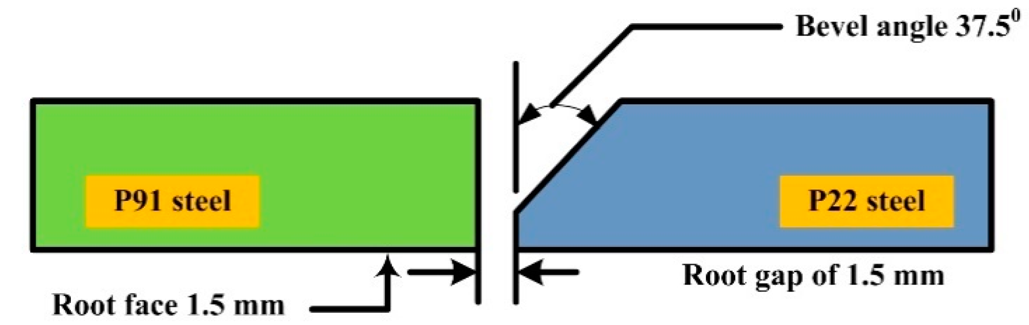
2. Experimental Details

The P22 and P91 steel plates of dimensions 120 mm×55 mm×10 mm were selected for the experiments. The chemical compositions in wt.% are as follows: P22 steel: C: 0.10, Cr: 1.91, Mo: 0.95, Mn: 0.34, Si: 0.36, Nb: 0.025, Ni: 0.20, Ti: 0.03, Cu: 0.18, balance Fe; P91 steel: C: 0.08, Cr: 8.24, Mo: 0.90, Mn: 0.46, Si: 0.23, V:0.18, Nb: 0.05, Ni: 0.24, Ti: 0.004, Cu: 0.04, balance Fe. The dissimilar, single bevel butt weld joint of P22 steel and P91 steel was produced using the gas tungsten arc welding (GTAW) process by employing IN82 and IN625 filler. Figure 1 shows the detail of single bevel groove geometry. The composition of filler metals and weld metals are given in Table 1. The composition of the base plate and weld metal was analyzed using optical emission spectrometer while filler composition was given by the supplier. The tensile strength, % elongation, and impact energy of the P91 steel were 715 MPa, 20%, 252 J, respectively. For P22 steel, tensile strength, % elongation, and impact energy were 610 MPa, 35%, and 320 J, respectively. The welding parameters are listed in Table 2. The arrangement of the plate before welding is presented in the schematic image (Figure 2).
Welding was performed in a shielding environment of argon which was supplied at a constant flow rate of 15 L/min. A standard metallographic technique, including grinding, polishing and etching, was done to reveal the weld metal microstructure. Samples were etched in an electrolytic solution at 9 V for 25 s. The formation of various sub-zones along the weldments is presented in Figure 2. To compare the impact strength of both the fillers, a standard notch of depth 2 mm was cut in the centre of the weld metal (Figure 2). The test was carried out on Charpy Impact Tester (FIT-400-ASTM-D) as per ASTM E23-02a standard. The microhardness measurement was performed in the weld metal for both the fillers and the indention load was kept at 500 g while dwell time was 10 s. To evaluate the room temperature tensile properties of the weldments, a tensile test was conducted on a standard tensile specimen (Figure 2) which were fabricated as per ASTM E8 standard.

3. Results and Discussion

3.1. As-Received Material

The microstructure of base metals is displayed in Figure 3a,b. A typical ferritic-bainitic matrix is seen for P22 steel while the SEM image shows the distribution of the precipitates within the bainitic matrix (Figure 3a). The precipitates were confirmed as M7C3, M23C6 and M3C of varying sizes and shapes [15]. The matrix contains the precipitates either along the bainitic lath blocks or grain boundaries. A tempered martensitic microstructure is seen for the P91 steel (Figure 3b). The distribution of the precipitates is seen along the prior austenite grain boundaries (PAGBs) and within the matrix (Figure 3b). The coarse precipitates of size 100–200 nm, decorated along the PAGBs were confirmed as Cr rich carbides (M23C6) whereas the fine precipitates within the matrix were V and Nb rich carbonitrides of size in a range of 10–50 nm. The grain size was measured 11 ± 4 µm and 15 ± 3 µm for P22 and P91 steel, respectively.

3.2. Microstructure Evolution near Interface and Weld Metal

The weld metal shows the austenitic microstructure with Ni weight percentage of 70.01% and 59.28% (Table 2), for IN82 and IN625 filler, respectively. The interface of the weld metal and P22 steel shows the macro segregation consists of the unmixed zone (UZ), type II boundary, peninsula and island, Figure 4a and Figure 5a [25]. The macro segregation is also noticed for the interface of the P91 steel and weld metal, Figure 4b and Figure 5b. The composition difference of the BMs and Ni-based filler leads to the macro segregation at the interface. Near the P22 steel interface for IN82 filler, a banding phenomenon is noticed, which is promoted by macro segregation and change in the solidification rate near the interface. Jula et al. [25] also reported the banding phenomena near the interface for DWJ of the P91 steel and AISI 316 steel. The weld metal near the interface was solidified as columnar dendrites (Figure 4c) for IN82 filler, whereas for IN625 filler, both columnar and cellular dendrite formation occurred (Figure 5c). The filler with high Ni content mainly solidifies in austenitic mode with distinct grain boundaries, including the solidification sub-grain boundary (SSGB), the solidification grain boundary (SGB), and the migrated grain boundary (MGB) as mentioned in Figure 4. The segregation of the alloying elements along the inter-dendritic areas and boundaries are also marked in Figure 4 and Figure 5.
The bulk weld metal shows the typical equiaxed dendritic microstructure for both the fillers (Figure 4d and Figure 5d) because they do not process any allotropic transformation. The segregation of the particles is also seen along the SSGBs and SGBs. For IN625 filler, less or negligible amounts of the migrated grain boundaries (MGBs) are seen, and it was mainly due to the higher density of the precipitates along SGBs, which stops the migration of the crystallographic component [26]. The IN82 filler mainly shows the presence of MGBs, whereas weld produces with IN625 have SGBs and SSGBs along with precipitates. The precipitates located along the SGBs provide the pinning effect to the crystallographic component and stop their migrations. Typical SEM images of bulk weld metal for both fillers are depicted in Figure 6. The major segregation of Nb and Ti particles is observed for IN82 filler, whereas for IN625 filler, major segregation is observed for Nb and Mo particles. The EDS spectra of the segregated particles and dendrite core for both the filler are presented in Table 3. The EDS results show the formation of Nb and Ti-rich carbides in IN82 filler weld whereas Nb, Cr and Mo-rich carbides of type NbC and Mo6C or M23C6 for IN625 filler. The SGBs, SSGBs and segregation of the alloying elements are marked in Figure 6 for both the filler metals.
In multi-pass welding, a wide region of a heat-affected zone (HAZ) contains large amounts of inhomogeneity in microstructure and mechanical properties. The P22 region adjacent to the fusion line contains coarse prior austenite grain (CPAG) bainite (Figure 7a) within the matrix of untempered bainite. The lath blocks (optical image) and undissolved precipitates (SEM image) are also observed in Figure 7a. The region of CPAG bainite is mainly exposed at temperature much higher than Ac3 that results in dissloltion of the grain boundary stabalizing precipitates. This promotes the significant grain growth in the CPAG bainite region. The region does not show any ferrite inclusion or pro-eutectoid ferrite formation. The P91 steel region adjacent to the fusion line contains an untempered martensitic matrix having coarse prior austenite grain (CPAG) martensite. The region shows similar behaviour to CPAG bainite. However, in place of bainitic blocks, martensitic lath blocks are observed withing the PAGs (Figure 7b). The region after the CPAG bainite is fine prior austenite grain (FPAG) bainite for P22 steel (Figure 7c) which experiences temperatures higher than or near to Ac3 and enables the partial dissolution of grain stabalizing precipitates. This results in finer grains in FPAG bainite than in CPAG bainite. The undissolved precipitates are also seen along the bainitic blocks and within the grain interior for FPAG bainite. The region of FPAG martensite that is adjacent to CPAG martensite contains untempered martensite, fine PAGs and few undissolved preipitates along the boundaries and grain interior (Figure 7d). The HAZ of P22 steel adjacent to over-tempered BM is referred as inter-critical HAZ (ICHAZ) where peak temperatures reach in between Ac1 to Ac3 and metal undergoes the partial transformation to austenite. The partial transformation of austenite leads to the formation of the complex microstructure which consists of the ferrite phase (tempered bainite/ferrite), i.e., untransformed ferrite (UF), and untempered bainite, i.e., austenite transformation products (ATP), as observed in Figure 7e. The ICHAZ of the P91 steel consists of the ferrite phase (tempered martensite/ferrite), i.e., UF and ATP (untempered martensite) (Figure 7f).

3.3. Mechanical Properties

3.3.1. Tensile Properties

Table 4 shows the tensile test results for all the trials and for both the filler. The ultimate tensile strength (UTS) was 715 ± 15 MPa and 610 ± 2 MPa for both P91 steel and P22 steel, respectively [8]. The UTS was measured 608 ± 3.5 MPa and 611 ± 4 MPa for both IN625 and In82 filler, respectively, which was close to the UTS of P22 BM. For each filler metal, three test coupons were tested and each test coupon was failed from the P22 BM instead of the weld metal. Hence, it can be stated that the joint is safe for end application. The P22 BM was recognized as the weakest portion of the welded joint. The variation in the filler metal composition has observed a negligible effect on the UTS value. The yield strength (YS) was 410 ± 2 MPa and 412 ± 2 MPa for IN625 and IN82 filler. The UTS and YS of the welded joint were measured lower than the P91 BM and were in the range of P22 BM. The joint efficiency lower than 100% for both the fillers was due to the fracture from week P22 BM. The % elongation of the welded joint was measured lower than the P22 BM but higher than the P91 BM. Hence, it can be stated that the filler composition has a negligible effect on the tensile properties of the dissimilar weldments of the P22 steel and P91 steel. For a similar type of joint with V groove geometry, the tensile failure was reported in P22 BM for ERNiCrCoMo-1 and the ERNiCrMo-3 filler weld with a tensile strength value of 618 ± 30 MPa and 615 ± 4 MPa [8,27]. The failure for the V groove butt joint was also observed in the region of P22 BM. Kumar et al. [23] also performed a comparative study for dissimilar weldments of P22 and P91 steel using the friction stir welding (FSW) and the activated-TIG process and observed better tensile properties for the A-TIG welded joint than FSW. The failure of the tensile test coupons was observed in the P22 BM for A-TIG and in the weld metal for FSW joint. Kulkarni et al. [22] also reported a similar observation for dissimilar A-TIG weldments of P22/P91 steel, i.e., failure of a tensile tested specimen from P22 BM. Hence, it is good to observe the results for single bevel groove geometry similar to the conventional V groove and A-TIG joint in low time and cost as a single bevel needs less filler metal.

3.3.2. Hardness and Impact Toughness

The hardness plot presented in Figure 7 indicates the composition gradient across the weldments. A similar trend of hardness variation is obtained for both the fillers. A gradual increase in hardness from weld metal to HAZ was observed on both sides and then decreased gradually from HAZ to BM. The hardness variation is influenced by the microstructural inhomogeneity along weldments. The weld metal hardness was 222 ± 8 HV and 255 ± 6 HV for the IN82 and IN625 filler, respectively. The higher hardness of the IN625 filler weld might be due to the higher segregation of alloying elements Mo and Nb than the IN82 filler, which resulted in increased precipitation hardening. The peak hardness of 448 HV was in P91 coarse-grained HAZ, whereas the lowest of the 207 HV was measured in the soft ICHAZ of P22 steel. The hardness in the coarse-grained HAZ of P22 steel was 352 HV and 367 HV for the IN82 and IN625 filler, respectively. The filler composition has observed a minute effect on the hardness of HAZ of P22 and P91 steel (Figure 8).
An impact toughness test was carried out at room temperature to measure the impact strength of the welded joint. The impact test of the weld metal was also conducted for both the filler composition and the notch was cut in the top region as well as the root region, as depicted in Figure 2. The impact toughness of the P91 and P22 BM was 105 J and 188 J [8]. The impact toughness of the IN625 filler weld for the V notch in the top region was measured to be 70 ± 5 J, which was lower than the IN82 filler weld (82 ± 6 J) (Table 5). The impact toughness for the V notch in the root region was measured to be 88 ± 5 J and 92 ± 4 J for the IN625 and IN82 filler weld, respectively. The poor impact toughness for the IN625 filler might be due to the higher segregation of Mo and Nb at inter-dendritic boundaries for the IN625 weld than the IN82 filler weld [8]. However, to meet the end application requirement for such type of dissimilar joint for a power plant application, the minimum impact toughness value was recommended at about 47 J (ISO 3580:2004) [29]. The impact toughness of the weld metal obtained for both the filler metals meets the essential criteria of 47 J. However, for a similar type of dissimilar joint with P91 filler, poor impact toughness of the weld metal was reported (lower than the 47 J) [16]. The poor impact toughness for the matching P91 filler was attributed to the formation of the lath martensitic microstructure in the weld metal. However, in the present investigation, due to the use of the Ni-based filler weld, it was solidified as an austenitic microstructure. For conventional V groove geometry with ERNiCrCoMo-1 filler and ERNiCrMo-3 filler, impact toughness was 96 J and 65 J, respectively. Kulkarni et al. [22] reported the impact toughness of the dissimilar P22/P91 A-TIG weldments lower than 47 J and hence the joint was not acceptable in the as-welded conditions. The dissimilar weldments’ impact toughness in the Ni-based filler is mainly governed by their dendritic microstructure and segregation of alloying elements.

4. Conclusions

The weldments of the P22 and P91 steel were manufactured by a single bevel groove joint using Ni-based IN625 and IN82 filler. The weldments were produced successfully without any defects. The following conclusion are drawn from the present analysis.
  • The microstructure characterization showed the macro segregation at the interface of the weld metal and BMs. The macro segregation at the interface was attributed to a variation in microstructure and the chemical composition of the Ni-based filler and BMs.
  • The weld showed the austenitic microstructure with a Ni weight percentage of 70.01% and 59.28% for the IN82 and IN625 filler. For the IN82 filler weld, Ti(C, N) and NbC were observed as a major phase, whereas for the IN625 filler, the major phase was M6C, M23C6 and NbC.
  • The tensile test coupons showed the failure from the P22 base metal in all the trials and for both the fillers, which confirmed the negligible effect of the filler composition on tensile properties and also that the joint was safe for boiler application.
  • The hardness of the IN82 filler weld was measured as lower than the IN625, which was attributed to the higher density of secondary phases along the inter-dendritic areas in the IN625 filler weld.
  • The impact toughness of the weld metal for both the filler was measured as lower than the BMs. The impact toughness of the IN82 filler weld was measured as higher than the IN625 filler weld, and that might be due to the higher segregation of the Nb and Mo in the IN625 filler weld.

Author Contributions

Data curation, S.K., S.S., S.M.P., D.B. and C.P.; Formal analysis, S.K., S.S. and S.M.P.; Funding acquisition, C.P., D.B. and S.M.P.; Investigation, S.K., S.M.P. and S.S.; Methodology, S.K., S.S., S.M.P. and C.P.; Project administration, S.M.P., C.P. and D.B.; Resources, S.S., S.M.P. and D.B.; Software, C.P. and S.S.; Visualization, D.B., S.M.P., S.K. and C.P.; Writing—original draft, S.K., S.S., S.M.P. and D.B.; Writing—review & editing, S.K., S.S., S.M.P. and C.P. All authors have read and agreed to the published version of the manuscript.

Funding

This research received no external funding.

Institutional Review Board Statement

Studies not involving humans or animals.

Informed Consent Statement

Not applicable.

Data Availability Statement

Not applicable.

Conflicts of Interest

The authors declare no conflict of interest.

References

  1. Ennis, P.J.; Czyrska-Filemonowicz, A. Recent advances in creep-resistant steels for power plant applications. Sadhana 2003, 28, 709–730. [Google Scholar] [CrossRef]
  2. Di Gianfrancesco, A. The Fossil Fuel Power Plants Technology; Elsevier: Amsterdam, The Netherlands, 2017. [Google Scholar] [CrossRef]
  3. Viswanathan, R.; Bakker, W. Materials for Ultrasupercritical Coal Power Plants—Boiler Materials: Part 1. J. Mater. Eng. Perform. 2001, 10, 81–95. [Google Scholar] [CrossRef]
  4. Abe, F. Progress in Creep-Resistant Steels for High Efficiency Coal-Fired Power Plants. J. Press. Vessel Technol. 2017, 138, 040804. [Google Scholar] [CrossRef]
  5. Viswanathan, R.; Sarver, J.; Tanzosh, J.M. Boiler Materials for Ultra-Supercritical Coal Power Plants—Steamside Oxidation. J. Mater. Eng. Perform. 2006, 15, 255–274. [Google Scholar] [CrossRef]
  6. Kaybyshev, R.O.; Skorobogatykh, V.N.; Shchenkova, I.A. New martensitic steels for fossil power plant: Creep resistance. Phys. Met. Metallogr. 2010, 109, 186–200. [Google Scholar] [CrossRef]
  7. Akram, J.; Kalvala, P.R.; Misra, M.; Charit, I. Creep behavior of dissimilar metal weld joints between P91 and AISI 304. Mater. Sci. Eng. A 2017, 688, 396–406. [Google Scholar] [CrossRef]
  8. Sauraw, A.; Sharma, A.K.; Fydrych, D.; Sirohi, S.; Gupta, A.; Świerczyńska, A.; Pandey, C.; Rogalski, G. Study on Microstructural Characterization, Mechanical Properties and Residual Stress of GTAW Dissimilar Joints of P91 and P22 Steels. Materials 2021, 14, 6591. [Google Scholar] [CrossRef]
  9. Landowski, M.; Świerczyńska, A.; Rogalski, G.; Fydrych, D. Autogenous Fiber Laser Welding of 316L Austenitic and 2304 Lean Duplex Stainless Steels. Materials 2020, 13, 2930. [Google Scholar] [CrossRef]
  10. Rogalski, G.; Świerczyńska, A.; Landowski, M.; Fydrych, D. Mechanical and Microstructural Characterization of TIG Welded Dissimilar Joints between 304L Austenitic Stainless Steel and Incoloy 800HT Nickel Alloy. Metals 2020, 10, 559. [Google Scholar] [CrossRef]
  11. Ghiasvand, A.; Suksatan, W.; Tomków, J.; Rogalski, G.; Derazkola, H.A. Investigation of the Effects of Tool Positioning Factors on Peak Temperature in Dissimilar Friction Stir Welding of AA6061-T6 and AA7075-T6 Aluminum Alloys. Materials 2022, 15, 702. [Google Scholar] [CrossRef]
  12. Tomków, J.; Sobota, K.; Krajewski, S. Influence of tack welds distribution and welding sequence on the angular distortion of tig welded joint. Facta Univ. Ser. Mech. Eng. 2020, 18, 611–621. [Google Scholar] [CrossRef]
  13. Kumar, A.; Pandey, C. Development and Evaluation of Dissimilar Gas Tungsten Arc-Welded Joint of P92 Steel/Inconel 617 Alloy for Advanced Ultra-Supercritical Boiler Applications. Metall. Mater. Trans. A 2022, 53, 3245–3273. [Google Scholar] [CrossRef]
  14. Sudha, C.; Terrance, A.; Albert, S.; Vijayalakshmi, M. Systematic study of formation of soft and hard zones in the dissimilar weldments of Cr–Mo steels. J. Nucl. Mater. 2002, 302, 193–205. [Google Scholar] [CrossRef]
  15. Bhanu, V.; Fydrych, D.; Gupta, A.; Pandey, C. Study on Microstructure and Mechanical Properties of Laser Welded Dissimilar Joint of P91 Steel and INCOLOY 800HT Nickel Alloy. Materials 2021, 14, 5876. [Google Scholar] [CrossRef] [PubMed]
  16. Sirohi, S.; Kumar, S.; Bhanu, V.; Pandey, C.; Gupta, A. Study on the Variation in Mechanical Properties along the Dissimilar Weldments of P22 and P91 Steel. J. Mater. Eng. Perform. 2022, 31, 2281–2296. [Google Scholar] [CrossRef]
  17. Paddea, S.; Francis, J.A.; Paradowska, A.M.; Bouchard, P.J.; Shibli, I.A. Residual stress distributions in a P91 steel-pipe girth weld before and after post weld heat treatment. Mater. Sci. Eng. A 2012, 534, 663–672. [Google Scholar] [CrossRef]
  18. Sudha, C.; Paul, V.T.; Terrance, A.L.E.; Saroja, S.; Vijayalakshmi, M. Microstructure and microchemistry of hard zone in dissimilar weldments of Cr-Mo steels. Weld. J. 2006, 85, 71–80. [Google Scholar]
  19. Sultan, A.R.; Ravibharath, R.; Narayanasamy, R. Study of Dissimilar Header Welding Between 2.25Cr–1Mo Steel and 9Cr–1Mo Steel with 9018 B9 Electrode Under Various Conditions of Post Weld Heat Treatment. Trans. Indian Inst. Met. 2017, 70, 2079–2092. [Google Scholar] [CrossRef]
  20. Albert, S.K.; Gill, T.P.S.; Tyagi, A.K.; Mannan, S.L.; Kulkarni, S.D.; Rodriguez, P. Soft zone formation in dissimilar welds between two Cr-Mo steels. Weld. J. 1997, 76, 135–142. [Google Scholar]
  21. Kulkarni, A.; Dwivedi, D.K.; Vasudevan, M. Dissimilar metal welding of P91 steel-AISI 316L SS with Incoloy 800 and Inconel 600 interlayers by using activated TIG welding process and its effect on the microstructure and mechanical properties. J. Mater. Process. Technol. 2019, 274, 116280. [Google Scholar] [CrossRef]
  22. Kulkarni, A.; Dwivedi, D.K.; Vasudevan, M. Study of mechanism, microstructure and mechanical properties of activated flux TIG welded P91 Steel-P22 steel dissimilar metal joint. Mater. Sci. Eng. A 2018, 731, 309–323. [Google Scholar] [CrossRef]
  23. Sunilkumar, D.; Muthukumaran, S.; Vasudevan, M.; Reddy, G.M. Microstructure and Mechanical Properties Relationship of Friction Stir- and A-GTA-Welded 9Cr-1Mo to 2.25Cr-1Mo Steel. J. Mater. Eng. Perform. 2021, 30, 1221–1233. [Google Scholar] [CrossRef]
  24. Tammasophon, N.; Homhrajai, W. Effect of Postweld Heat Treatment on Microstructures and Hardness of TIG Weldment between P22 and P91 Steels with Inconel 625 Filler Metal. J. Met. Mater. Miner. 2011, 21, 93–99. [Google Scholar]
  25. Jula, M.; Dehmolaei, R.; Zaree, S.R.A. The comparative evaluation of AISI 316/A387-Gr.91 steels dissimilar weld metal produced by CCGTAW and PCGTAW processes. J. Manuf. Process. 2018, 36, 272–280. [Google Scholar] [CrossRef]
  26. Hosseini, H.S.; Shamanian, M.; Kermanpur, A. Characterization of microstructures and mechanical properties of Inconel 617/310 stainless steel dissimilar welds. Mater. Charact. 2011, 62, 425–431. [Google Scholar] [CrossRef]
  27. Kumar, S.; Sirohi, S.; Vidyarthy, R.S.; Gupta, A.; Pandey, C. Role of the Ni-based filler composition on microstructure and mechanical behavior of the dissimilar welded joint of P22 and P91 steel. Int. J. Press. Vessel. Pip. 2021, 193, 104473. [Google Scholar] [CrossRef]
  28. Thakare, J.G.; Pandey, C.; Mahapatra, M.M.; Mulik, R.S. An assessment for mechanical and microstructure behavior of dissimilar material welded joint between nuclear grade martensitic P91 and austenitic SS304 L steel. J. Manuf. Process. 2019, 48, 249–259. [Google Scholar] [CrossRef]
  29. ISO 3580:2004; Welding Consumables—Covered Electrodes for Manual Metal Arc Welding of Creep-Resisting Steels. ISO: Geneva, Switzerland, 2004.
Figure 1. Schematic showing the bevel groove geometry.
Sustainability 14 11739 g001
Figure 2. Schematic diagram showing arrangement of plates, sub-zone formation across weldments, extraction of mechanical and metallographic testing specimen, and dimension of the specimens.
Sustainability 14 11739 g002
Figure 3. Microstructure of base material: (a) P22 steel, (b) P91 steel.
Sustainability 14 11739 g003
Figure 4. Characterization of weld metal and interface for IN82 filler: (a) interface of weld metal and P22 steel, (b) interface of weld metal and P91 steel, (c) weld metal near the interface, (d) bulk weld metal.
Sustainability 14 11739 g004
Figure 5. Characterization of weld metal and interface for IN625 filler: (a) interface of weld metal and P22 steel, (b) interface of weld metal and P91 steel, (c) weld metal near the interface, (d) bulk weld metal.
Sustainability 14 11739 g005
Figure 6. SEM image of bulk weld metal for (a) IN82 filler, (b) IN625 filler.
Sustainability 14 11739 g006
Figure 7. CPAG region: ((a) P22, (b) P91); FPAG region ((c) P22, (d) P91); inter-critical HAZ ((e) P22, (f) P91).
Sustainability 14 11739 g007
Figure 8. Hardness indent plot along weldments.
Sustainability 14 11739 g008
Table 1. Chemical composition of the base plates, filler metals and weld metals.
ElementCMnSiCrMoNbNiTiCuVFe
Filler wire ER NiCrMo-3 (IN625)0.010.360.0420.289.383.8562.890.150.01-0.38
Filler wire ERNiCr-3 (IN82)0.023.070.1819.10-2.3572.830.290.01-0.14
Weld metal ER NiCrMo-3 (IN625)0.010.270.0321.389.053.3859.280.240.020.015.18
Weld metal ERNiCr-3 (IN82)0.012.600.1420.050.522.2370.010.310.0040.024.05
Table 2. Welding process parameters employed in GTAW.
PositionWelding Current (amp)Arc Voltage (V)Shielding Gas Pure Ar (L/min)Electrode Diameter/Tip
Angle
Electrode Material Heat Input (kJ/mm)Travel Speed (mm/s)
Root pass (Top side)12012–13152.9/60°2% Thoriated Tungsten1.271.2
Filling pass 113214–152.360.8
214216–172.690.857
314016–172.690.857
414817–183.350.774
514817–183.350.774
Table 3. EDS result of the white particle and dendrite core for IN625 and IN82 filler.
Filler MetalEDS Location CTiCrFeNiNbMo
IN625 fillerWhite particle8.520.4219.259.8638.6112.8210.52
Dendrite core9.450.2517.5211.8548.45.686.85
IN82 fillerWhite particle-0.8218.523.5255.7120.850.58
Dendrite core-0.1520.126.8269.642.850.42
Table 4. Tensile test results.
SampleYield Strength (MPa)Tensile Strength (MPa)% Elongation (% e)Fracture LocationJoint Efficiency (%) [28]
P91 base metal [24]475 ± 25715 ± 1520 ± 2--
P22 base metal495 ± 5610 ± 235--
N625 filler Sample 1408410 ± 2608608 ± 3.52627 ± 1P22 base85
Sample 241260528P22 base
Sample 341061227P22 base
IN 82 filler Sample 1415412 ± 2610611 ± 42526 ± 1.5P22 base85
Sample 241261528P22 base
Sample 341060726P22 base
Table 5. Impact toughness of weld metal for IN625 and IN82 filler.
Impact Toughness AW
IN625 fillerImpact toughness (weld metal: top)70 ± 5 J
Impact toughness (weld metal: root)82 ± 6 J
IN 82 fillerImpact toughness (weld metal: top)88 ± 5 J
Impact toughness (weld metal: root)92 ± 4 J
Publisher’s Note: MDPI stays neutral with regard to jurisdictional claims in published maps and institutional affiliations.

