Abstract
This study prepared an alkali-activated soda residue (SR)-blast furnace slag (BFS) composite binder by adding a large amount of SR to the alkali-activated material system. Considering many factors, such as the Na2O content, ratio of SR to BFS and the water-binder ratio, the variation patterns in the new binder’s mechanical properties and its micro-evolution mechanisms were assessed. The results show that the compressive strength first grew and then dropped with the Na2O content, with an optimal level at 3.0%. At this level, the strength values of the 3d and 28d samples were 10.5 and 27.8 MPa, respectively, exceeding those in the control group without Na2O by 337.5 and 69.5%, respectively. As the Na2O admixture increased from 0 to 3%, the fluidity of the mortar decreased from 156 mm to 127 mm due to the high frictional resistance caused by the faster generation of hydration products, and the high water absorption of SR also led to reduced fluidity. The new binder’s hydration process mainly generated C-(A)-S-H gel, ettringite (ET), hydrocalumite (HC), calcium hydroxide (CH), and other crystalline hydrates. A 3% Na2O content inhibited the ET growth but significantly promoted the formation of uniformly distributed C-(A)-S-H gel and HC. Crystals grew in the pores or were interspersed in the gel, filling microcracks and significantly increasing the structure density and strength. Excessive Na2O (>3%) could promote the generation of non-uniformly distributed gel, producing more macropores in the matrix and reducing its strength. Additionally, the increased SR content was not conducive to C-(A)-S-H gel formation, but significantly promoted ET formation, which would inhibit strength development. This study provides a theoretical basis for replacing cement with this new binder in pavement bricks and other unreinforced products.
1. Introduction
After decades of development, alkali-activated binders are considered the most lucrative cement substitute in construction. Compared with the complicated manufacturing process of cement, alkali-activated binders have the advantages of low energy consumption, fewer CO2 emissions, and substantial environmental benefits [1,2]. Among various alkali-activated binders, the alkali-activated blast furnace slag binder (AAS) has been extensively studied worldwide. As early as 1940, Purdon [3] used different activators (caustic alkali such as NaOH, other alkaline salts, etc.) to activate various types of BFS, systematically studied the strength development of AAS, and found that it had better tensile and flexural properties and low hydration heat release. Subsequently, this kind of binder has become a strong focus for research.
The mechanical properties of AAS are related to many factors, such as the physical and chemical properties of raw materials (e.g., fineness, chemical composition, activity), the type and content of activator, and curing conditions, etc. [4,5]. Generally, AAS has a short setting time and rapid early strength development [6,7], and its one-day strength can reach more than 40 MPa, which is due to the rapid hydration of BFS attributable to high pH activation. Marvila et al. [7] investigated the feasibility of using alkali activated cements based on BFS as an alternative to ordinary Portland cement. The results showed that the system had the highest compressive strength at 10% Na2O, and had lower porosity and better durability. Asaad et al. [8] prepared a new AAS using different levels (5, 10, 15, 20, 25%) of metakaolin instead of BFS and found that the 28-day compressive strength of the mortar samples with 10% metakaolin was 63.4 MPa. Metakaolin addition significantly reduced the drying shrinkage of the samples, decreased the porosity and carbonation depth and improved the corrosion resistance. In recent years, some solid waste materials have been introduced into AAS to prepare new composite binders, reducing the cost and enabling the reuse of other solid wastes. Islam et al. [9] used NaOH + NaSiO3 to activate the composite precursor material of palm oil fuel ash and BFS followed by curing at 65 °C for 24 h. They reported that the optimal ratio of palm oil fuel ash and BFS was 3:7, and the 28d strength could reach 66 MPa. Nasir et al. [10] also used NaOH + NaSiO3 to activate the composite precursor material containing 70% silicon manganese soot and 30% BFS. It was found that curing at 60 °C for 6 h was the optimal curing condition, and the compressive strength values at 3d and 28d were 37.8 and 45.2 MPa, respectively. The addition of other solid wastes could affect the mechanical properties and hydration process of AAS and address some disadvantages of AAS, such as delayed setting time. Therefore, this kind of new composite binder has gradually become a strong research focus.
Soda residue (SR) is the waste residue produced in the soda industry of the ammonia alkali process. Its main chemical components include CaO, a small amount of SiO2, Al2O3, and a high chloride content [11,12]. Each ton of soda produced in this process generates 300–600 kg of SR, and over 7 million tons of solid SR are generated annually in China [13]. Due to this large volume of SR and the few ways the resource can be utilized, most factories mainly deal with SR by outward transportation and accumulation, which requires much land and results in soil and groundwater pollution [14]. Some factories even directly discharge the SR into the sea, polluting the seawater and jeopardizing its flora and fauna. Therefore, more effective and safe utilization of SR is very topical from both environmental and economic standpoints.
Scholars have recently conducted resource utilization research on SR based on its physical and chemical properties, mainly in the areas of soil improvement, harmful ion adsorption, and building material manufacturing. In terms of soil improvement, the main chemical composition of SR is insoluble salts. After mixing with fly ash, cement and other materials, it can form SR soil, which can be used for low-lying land filling, underground tunnel backfilling or road foundations [15,16]. Since the SR’s solid structure comprises aggregates with many pores and good adsorption properties, it can be used for desulfurization or adsorption of harmful ions in various metallurgical industries [17]. In addition, SR is rich in Ca, Si, and Al, making it similar to cement clinker and applicable to cement production. Thus, Uçal et al. [18] prepared Alinite cement with SR as a raw material and reported that the prepared cement had a shorter induction period (between 15 and 20 min) than ordinary Portland cement. The addition of 12% gypsum could increase the amount of ettringite in hydration products and significantly improve the compressive strength. Wang et al. [14] mixed SR with cement, ground it and calcined it to prepare composite cement. At a 5% SR content, the 28d compressive strength reached 53 MPa and the contents of CaO and Cl− in the clinker met the requirements of relevant standards, but the frost resistance and impermeability were weakened.
In recent years, the research on the preparation of new binders with SR has gradually increased. It mainly includes the following two main approaches: (1) using SR as an activator, since the alkali contained in SR could replace strong alkali to activate aluminosilicate raw materials, and (2) preparation of composite binders by adding SR to conventional alkali-activated materials. Within the framework of the first approach, Liu [19] and Lin [20] adopted SR to activate BFS and prepare binders with a 28d strength exceeding 30 MPa. However, their 3d and 7d strength values were less than 5 MPa, which limited their engineering application. Besides, the contents of SR were small (less than 20%), which implied insufficient SR utilization. Alternatively, Guo et al. [21,22] used SR and carbide slag to activate BFS-fly ash for preparing a binder system with strengths ranging from 17 to 40 MPa, but this preparation also only required a low content of SR. In the second approach, which involves adding SR to conventional alkali-activated materials, Zhao et al. [16] added SR to a sodium silicate-activated fly ash cementitious system. At an SR content of 40%, a 2 mol/L concentration of sodium silicate solution, and the liquid-solid ratio of 1.2, relatively good fluidity and compressive strength (3.7 MPa) were obtained, which were sufficient for goaf backfilling applications. As for the hydration products of SR-based binders, high chloride contents have been reported to promote the formation of Friedel’s salt, improving the matrix strength [21,23,24].
The above brief survey strongly indicates that the SR-based preparation of clinker-free binders is still in the preliminary exploration stage. In most studies, the amounts of SR were too small to mitigate the environmental problems caused by the rapid accumulation of SR. Therefore, in this study, a large amount of SR was introduced into the alkali-activated material system to prepare an alkali-activated SR-BFS composite binder. The optimum mechanical properties were obtained by optimizing the activator content, and the microstructure evolution process was systematically studied to reveal the hydration mechanism. This study aims to provide a solution to the problems of environmental pollution and land waste caused by the large-scale accumulation of SR.
2. Materials and Methods
2.1. Raw Materials
The raw materials included SR, BFS, NaOH, standard sand, and water. The chemical composition, particle size distribution, micromorphology, and phase composition of SR and BFS were assessed via XRF, laser particle size analyzer, SEM, and XRD, respectively. The specific surface area was measured by gas adsorption using the BET method, and the density was assessed via the density bottle method. The results are summarized in Table 1 and plotted in Figure 1, Figure 2 and Figure 3.

Table 1.
Chemical composition and physical properties of raw materials.
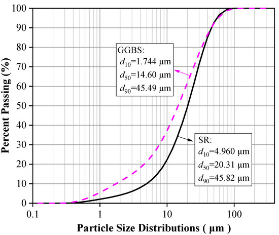
Figure 1.
Particle size distributions of SR and GGBS.
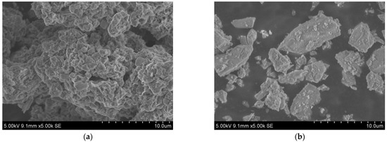
Figure 2.
SEM images of (a) SR, (b) GGBS.
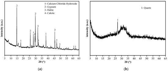
Figure 3.
XRD spectra of (a) SR, and (b) GGBS.
The SR with an initial moisture content exceeding 90% was acquired from the Tangshan Sanyou Alkali-Chlor Co., Ltd. (China). The SR samples were prepared as follows. First, the samples were left to stand for layering to occur. The clear upper liquid was then removed and the sedimentary layer was stirred evenly. When the moisture content of the sedimentary layer was reduced to 50–60%, the sediments were oven-dried, ground, and sieved with a 0.15 mm square hole sieve to obtain SR powder with an average particle size of 20.31 μm (Figure 1). The density of the SR powder was 2351 kg/m3, and the specific surface area was 261.2 m2/kg (Table 1). The micromorphology was agglomerated with many pores, as shown in Figure 2a. The main chemical components were CaO and Cl−, and small amounts of SiO2, Al2O3, MgO (Table 1). The main phases were calcium chloride hydroxide, gypsum, halite, and calcite (Figure 3a). The S95 grade BFS was utilized and had an average particle size of 14.60 μm (Figure 1), a 2742 kg/m3 density, and a 419.5 m2/kg specific surface area. The main chemical components were CaO, SiO2, and Al2O3 (Table 1), and the main phase was quartz (Figure 3b). As seen in Figure 2b, the micromorphology was irregular blocks. NaOH was a granular analytical reagent with a content exceeding 96%. The acquired standard sand, with a particle size range of 0.08–2.0 mm and mud content below 0.2%, complied with the Chinese standard GB/T17671. Tap water from the laboratory was used to ensure the required water-binder ratios.
2.2. Mixing Ratio Design
This study introduced a large amount of SR into AAS to prepare a new composite binder. Through preliminary exploratory tests, the initial SR and BFS shares were set to 40 and 60%, respectively, to ensure the maximal long-term strength. Firstly, the Na2O content effect on the binder’s properties was investigated. The Na2O content was defined as the ratio of Na2O mass contained in NaOH to the mass of binders. The designed contents of Na2O were 0, 0.5, 1.0, 1.5, 2.0, 3.0 and 4.0%. The optimum content of Na2O was determined according to the maximal compressive strength. On this basis, the effects of the ratio of SR to BFS and water-binder ratio on the binder’s properties were further studied. In compliance with the evaluation method of Portland cement performance in Chinese standard GB/T 17671 [25], the water-binder ratio was fixed at 1:2, and the binder-sand ratio was fixed at 1:3. The mix proportions of mortar and paste are shown in Table 2. The mortar samples were tested to assess the compressive strength and fluidity, and the paste samples were used for XRD, TG-DTG, FTIR, and SEM analyses.
Table 2.
Mix proportion design.
2.3. Preparation of Samples
The preparation process of the paste and mortar samples was as follows. The amount of water required for the particular water-binder ratio was calculated before the test. Then, the NaOH particles were dissolved in the water and left for 2–4 h. During the test, the NaOH solution was first poured into the mixing pot, then, the SR and BFS were added. The mixture was stirred at a 140 r/min rotation rate for 1 min, and then was stirred at 285 r/min for 2 min to obtain the paste. At this point, the standard sand was added to the mixture. The mixture was stirred at 140 r/min for 30 s, and then was stirred at 285 r/min for 1.5 min to obtain the mortar.
After the mixing process was completed, the paste (or mortar) was loaded into the test mold in two layers, and the mold was vibrated for 60 s on the vibration table after each layer was loaded. The surface was smoothed with a leveling ruler. After the pouring process, the test mold was placed into a curing box with a temperature of 20 ± 1 °C and relative humidity of no less than 90% for 24 h. Then, the test mold was removed, and the samples were numbered and cured in the curing box until the predetermined age.
2.4. Experimental Method
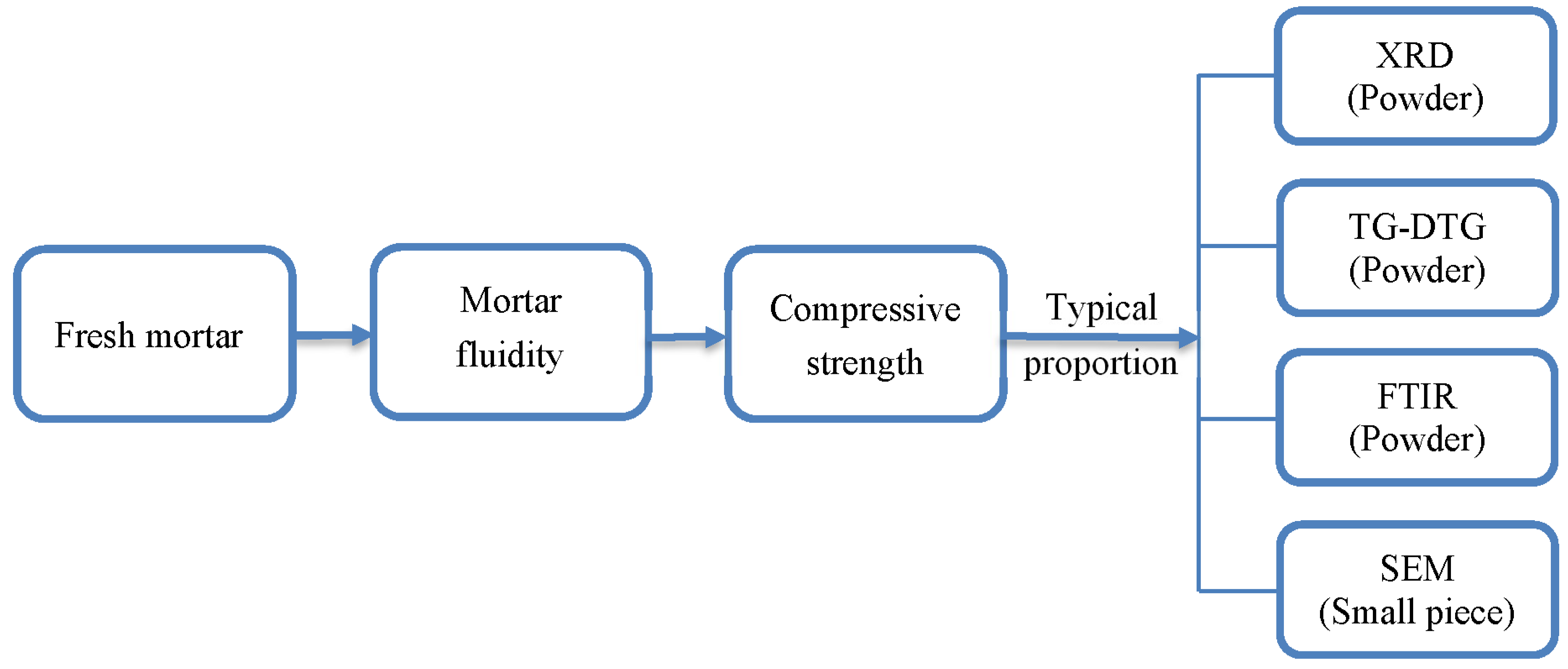
In this study, the macro-performance tests measured the mortar samples’ compressive strength and fluidity. The microstructural tests including XRD, TG-DTG, FTIR, and SEM were performed on the paste samples. The experimental flowchart is shown in Figure 4.
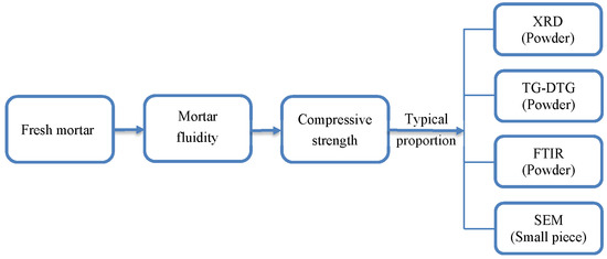
Figure 4.
Experimental flowchart.
According to Chinese standard GB/T 17671 [25], the prism-shaped mortar samples with 40 mm × 40 mm × 160 mm dimensions should be used for the compressive strength test. The curing ages were 3, 7, 28, 56d, and three specimens were selected for each mixing ratio and curing age. The samples were subjected to static compressive loading at a loading rate of 2.4 ± 0.2 kN until they failed. The average and standard deviations of six test values on three test samples were taken as the test results. The mortar fluidity tests complied with the Chinese standard GB/T 2419 [26]. The fresh mortar was loaded into the truncated cone circular mold in two layers, the first and second layers being uniformly tamped fifteen and ten times, respectively. Then, the mold was lifted; after 25 jumps on the jumping table, the bottom diameter of the mortar was measured with a ruler. Each mixing ratio was tested three times, and the average value and standard deviation were taken as the test results.
Cubic paste samples with 50 mm × 50 mm × 50 mm dimensions were prepared for the microscopic tests. The test samples were broken into blocks at the predetermined curing age and dried by the following procedure [27]. They were first soaked in isopropanol solution for 24 h and then soaked for 6d after replacing the isopropanol solution. Finally, the samples were vacuumed continuously in a vacuum dryer until the solvent volatilized fully. For the XRD, TG-DTG, FTIR tests, the dry blocks were ground into powder and passed through a 0.075 mm square-hole sieve. The maximum side length of the block in the SEM test did not exceed 10 mm. The XRD test parameters were as follows: Cu target, tube voltage of 40 kV, tube current of 40 mA, scanning angle range of 5~65°, and scanning speed of 2°/min. The TG-DTG parameters were as follows: a temperature range from room temperature to 1000 °C, Argon as a shielding gas, and a heating rate of 10 °C/min. The FTIR test involved a wavenumber range of 400 ~ 4000 cm−1 and a 2 cm−1 resolution. The SEM test was conducted via a TESCAN-VEGA3 scanning electron microscope.
3. Results and Discussion
3.1. Compressive Strength
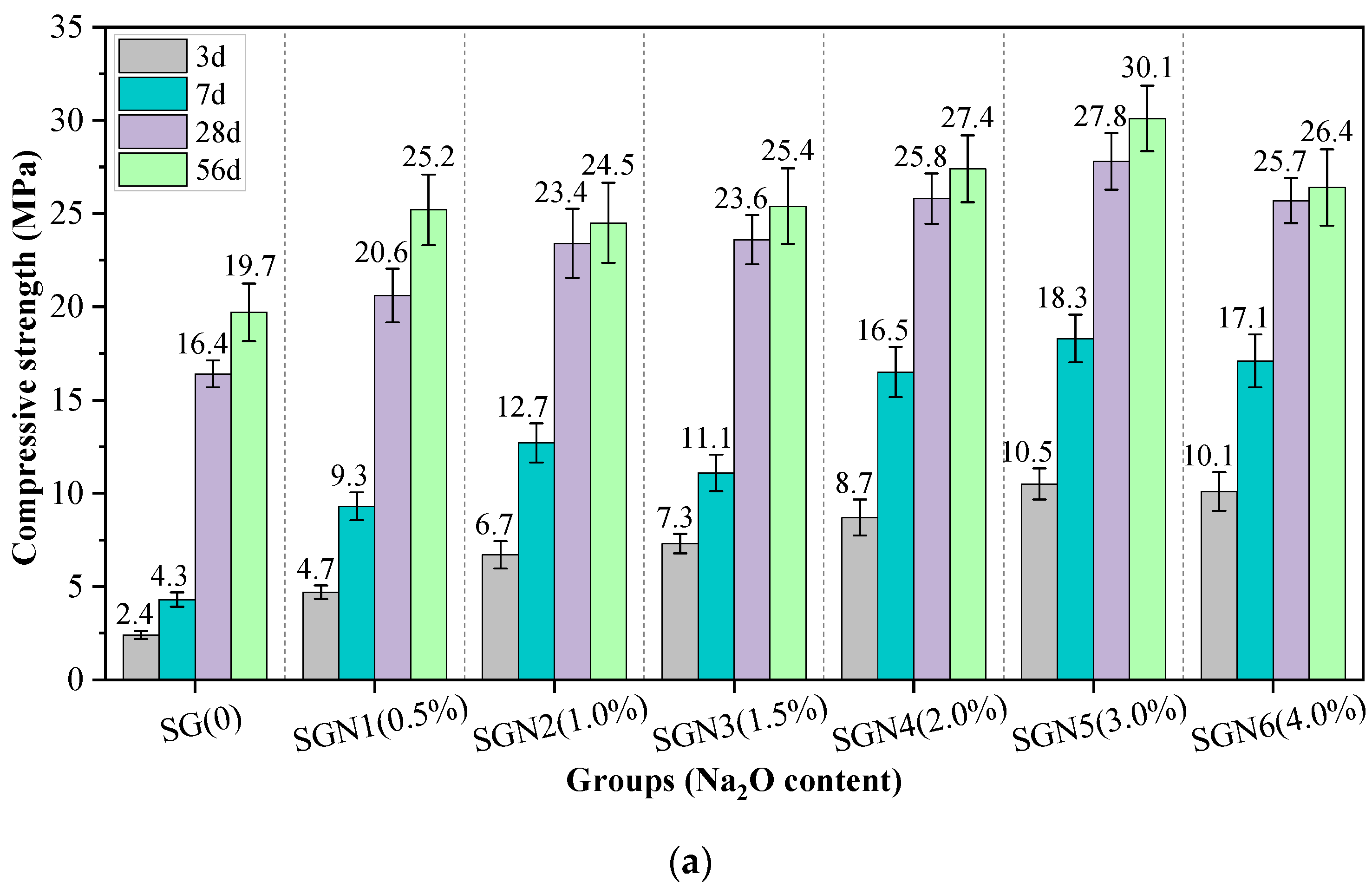
Figure 5 shows the compressive strength values of all the tested mortar samples of various curing ages. The effects of Na2O content, SR to BFS ratio, and water-binder ratio on the compressive strength were considered.
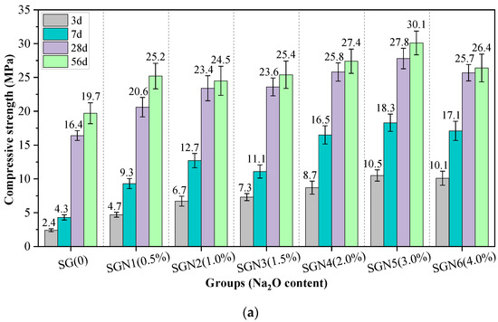
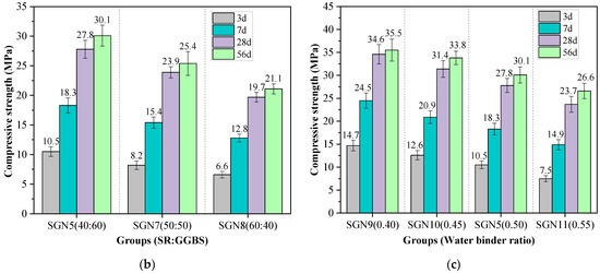
Figure 5.
Test results of compressive strength: (a) effect of Na2O content; (b) effect of SR to GGBS ratio; and (c) effect of water-binder ratio.
According to Figure 5a, the early strength development of SR-BFS composite binder (SG) without NaOH was very slow, and the 3d and 7d strength values were only 2.4 and 4.3 MPa, respectively. However, with increased curing age, the 28d and 56d strength reached 16.4 and 19.7 MPa, respectively, indicating that the alkalinity in SR stimulated the activity component of the SR-BFS composite precursor. Still, this excitation effect was mainly observed in the later stage, similar to previous research results [19,20]. When the NaOH (Na2O) was mixed with SG, the compressive strength at each curing age grew first and then dropped with increased amounts added, similar to previous research results [7]. At an Na2O content of 3.0%, the early and late strengths were the highest, the 3d and 28d strengths were 10.5 and 27.8 MPa, respectively, exceeding those of SG mixtures by 337.5% and 69.5%, respectively. The possible reason was that the addition of NaOH significantly enhances the system’s alkalinity, promoting the activation of the active components of composite precursor and accelerating the formation of C-(A)-S-H gel [28]. This rapidly improves the strength. Notably, excessive NaOH could reduce the strength, and this finding was consistent with previous studies [29,30]. The reason may be that although too high alkalinity can promote rapid hydration of the precursors, the excessive formation rate of gel products leads to their inadequate dissolution, transformation, and precipitation, resulting in rapid accumulation and encapsulation in the precursor particles. The gel is then unevenly distributed, forming more pores and preventing further strength development [30,31].
According to Figure 5b, with an increase in the SR-BFS ratio, the compressive strength at each curing age decreased gradually. This is because BFS is the main precursor in SR-BFS composite precursors, and the BFS decline means the decrease of active substances; the amount of gel products in the hydration reduces, resulting in strength reduction. Although the CaSO4 in the SR can promote the formation of ettringite in the system (conducive to early strength growth) [32], and the CaCO3 crystals in the SR also have a microaggregate effect (improving the structural compactness) [33], these effects did not play a decisive role in the strength development. According to Figure 5c, the compressive strength at each curing age decreased gradually with an increase in the water-binder ratio, which is consistent with that of cement-based materials. This is because the increase in the water-binder ratio increases the free water content in the system. Thus, the number of blisters formed by excess water after hardening or pores formed by water evaporation increases, reducing the structural compactness and causing a decrease in strength.
3.2. Mortar Fluidity
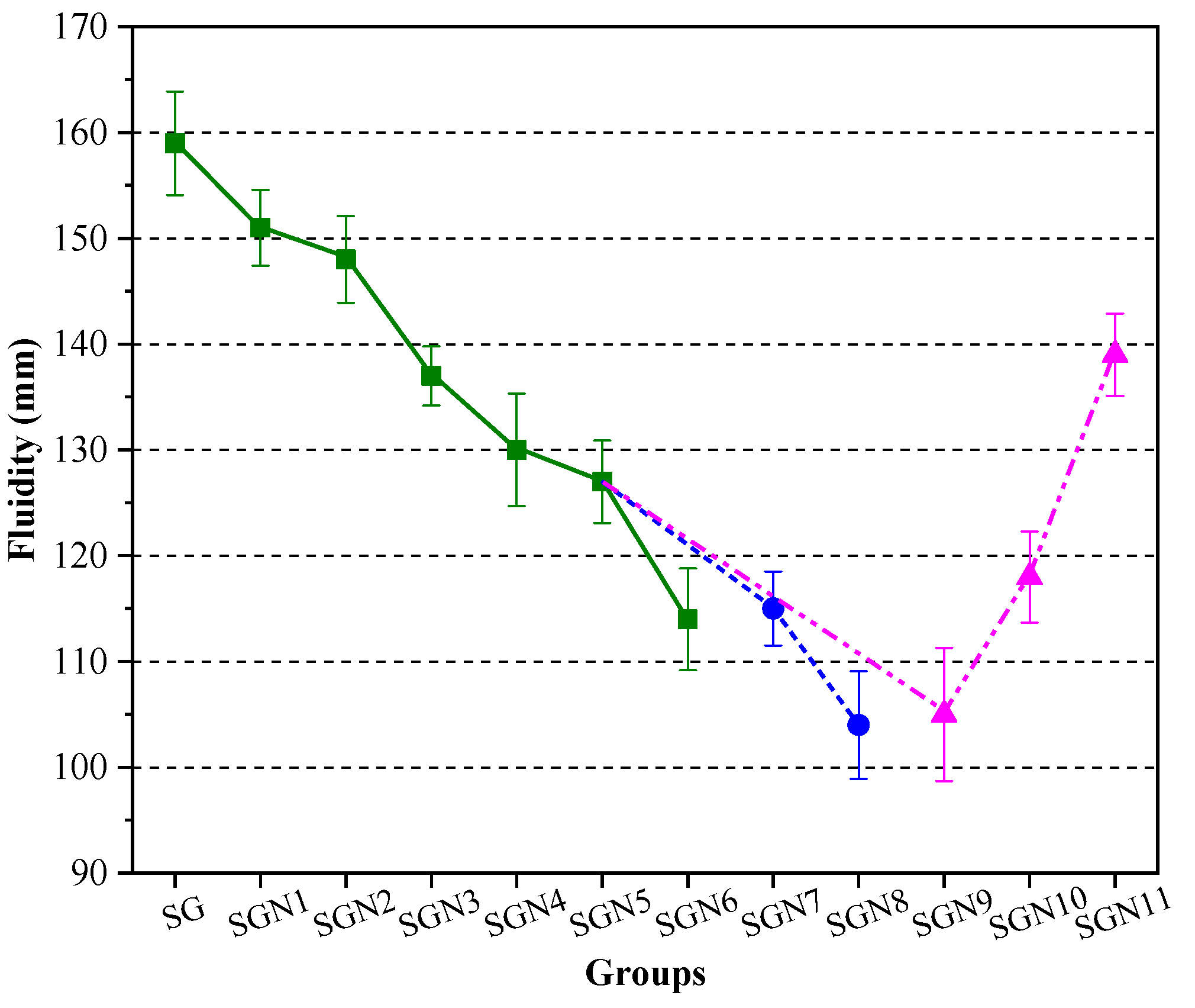
Mortar fluidity reflects the water demand of new binders and is also an important workability index of binders. Figure 6 shows the fluidity test results for all the tested fresh mortar samples.

Figure 6.
Test results of mortar fluidity.
It can be seen in Figure 6 that the fluidity of the SG group without NaOH was the highest, namely 159 mm. The fluidity decreased with the increase in NaOH content. At a Na2O content of 3.0%, the fluidity decreased to 127 mm, i.e., by 20.1%. This may be caused by the following reasons: the NaOH accelerates the hydration reaction of the SR-BFS composite precursors so that the hydration products (such as C-(A)-S-H gel and others) can be rapidly generated, increasing the internal friction resistance of the mortar and reducing the fluidity [34,35]. According to the results on SGN5, SGN7 and SGN8 samples, with an increase in the SR-BFS ratio, the fluidity of the mortar gradually decreased from 127 to 115 and then to 104 mm. This is because the SR particles are prone to agglomerate, rich in pores, and the water absorption ability is strong. When the SR content increases, the number of adsorbed water molecules increases under the same water consumption, reducing the free water content and fluidity. According to the SGN5 and SGN9–11 results, the fluidity grew with the water-binder ratio, which is consistent with the properties of cement. This is because the increased water-binder ratio significantly increases the amount of free water in the mortar, weakens the internal friction of the mortar, and improves the fluidity.
3.3. XRD Analysis
To determine the hydration products of the new binders and characterize the effects of Na2O content and SR-BFS ratio on the hydration products, XRD tests at the age of 28d were conducted on five groups of samples (SG, SGN2, 5, 6, 8). The test results are shown in Figure 7.
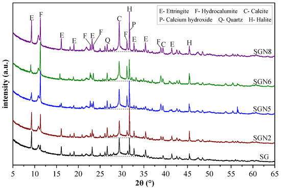
Figure 7.
XRD patterns of 28d samples.
As seen in Figure 7, six main crystal phases were detected, among which ettringite (3CaO·Al2O3·3CaSO4·32H2O), hydrocalumite (3CaO·Al2O3·CaCl2·10H2O, Friedel’s salt), and calcium hydroxide [Ca(OH)2] were the main crystal hydration products. These were generated by Cl−, CaSO4, CaO, and Al2O3 provided by SR-BFS composite precursors under the activation of NaOH. Quartz (SiO2) emerged from the BFS, and calcite (CaCO3) from the SR or carbonation of Ca(OH)2. Halite (NaCl) was formed by combining free Cl− and Na+ ions.
According to Figure 7, the main hydration products, namely ettringite (ET), hydrocalumite (HC), and calcium hydroxide (CH), showed obvious variation. In the SG group (without NaOH), the diffraction peak intensity of ET was strong, in contrast to HC and CH. When 1.0% Na2O was added to SG, the peak intensity of ET decreased slightly, whereas those of HC and CH increased significantly. When the content of Na2O was increased to 3.0%, the peak intensity of ET decreased significantly, whereas that of HC increased significantly, and that of CH changed little. This indicates that the increased amount of NaOH inhibited the ET growth but promoted the growth of HC and CH. When the content of Na2O was further increased to 4.0%, the peak intensities of ET, HC, and CH no longer changed significantly, indicating that excessive Na2O contents no longer played a role in the variation of hydration products. By comparing SGN5 and SGN8 samples, the peak intensities of ET and CH in SGN8 increased significantly. Still, the peak intensity of HC did not change significantly, indicating that an increase in the SR content promoted the formation of ET and CH but had little effect on HC. Previous studies [29,36] have shown that the early growth of ET can promote hardening, which is conducive to early strength formation, but the later formed high-content ET tends to expand and cause cracking, harming the late strength formation. The growth of HC can better fill the matrix pores, which is generally considered beneficial to the strength development [23]. Combined with the strength development described in Section 3.1, it can be seen that a suitable amount of NaOH can promote the growth of the favorable crystal product HC and inhibit the growth of the harmful crystal product ET, which makes a certain contribution to the strength development.
The diffraction peak intensity of quartz decreased gradually with Na2O content because the high alkalinity of NaOH significantly promoted the dissolution of the quartz phase, in which silicon participated in the formation of C-(A)-S-H gel [31,37]. Especially when the Na2O content increased from 1.0 to 3.0%, the peak intensity decreased significantly, indicating that the gel production increased significantly. However, the peak intensity remained unchanged when the content reached 4%, indicating that the promotion effect on gel formation was saturated. The quartz peak intensity of SGN8 was the lowest due to the low content of BFS in the system. With an increase in Na2O content, the diffraction peak intensity of calcite first decreased slightly and then increased gradually. The reason might be that when a small amount of NaOH was introduced into the system, a small amount of calcite was decomposed into Ca2+, participating in the hydration reaction. When more NaOH was added, it was prone to carbonation during solidification and sample treatment, increasing the amount of calcite. The calcite peak of SGN8 was the strongest, obviously caused by the high content of SR in the system. The diffraction peak intensity of halite increased first and then decreased with Na2O content. At an Na2O content of 1.0%, the peak intensity of halite increased significantly compared with SG because NaOH introduced a large amount of Na+, significantly promoting the formation of halite. When the content of Na2O was increased to 3.0%, and then to 4.0%, the peak intensity of halite gradually decreased, which might be because the high content of NaOH significantly promoted the formation of HC and consumed more Cl−, thus inhibiting the formation of halite. The halite peak of SGN8 was the strongest, obviously due to the high content of SR and NaOH in the system, and more halite was formed by Cl− and Na+ ions.
Additionally, “humps” representing the amorphous phase appeared in the 25–35° range of all the diagrams, indicating that the amorphous C-(A)-S-H was formed by a hydration reaction [29,38,39]. With increased Na2O content, the width and height of these “humps” increased, indicating that the gel production was enhanced, which is conducive to a growth in strength.
3.4. TG-DTG Analysis
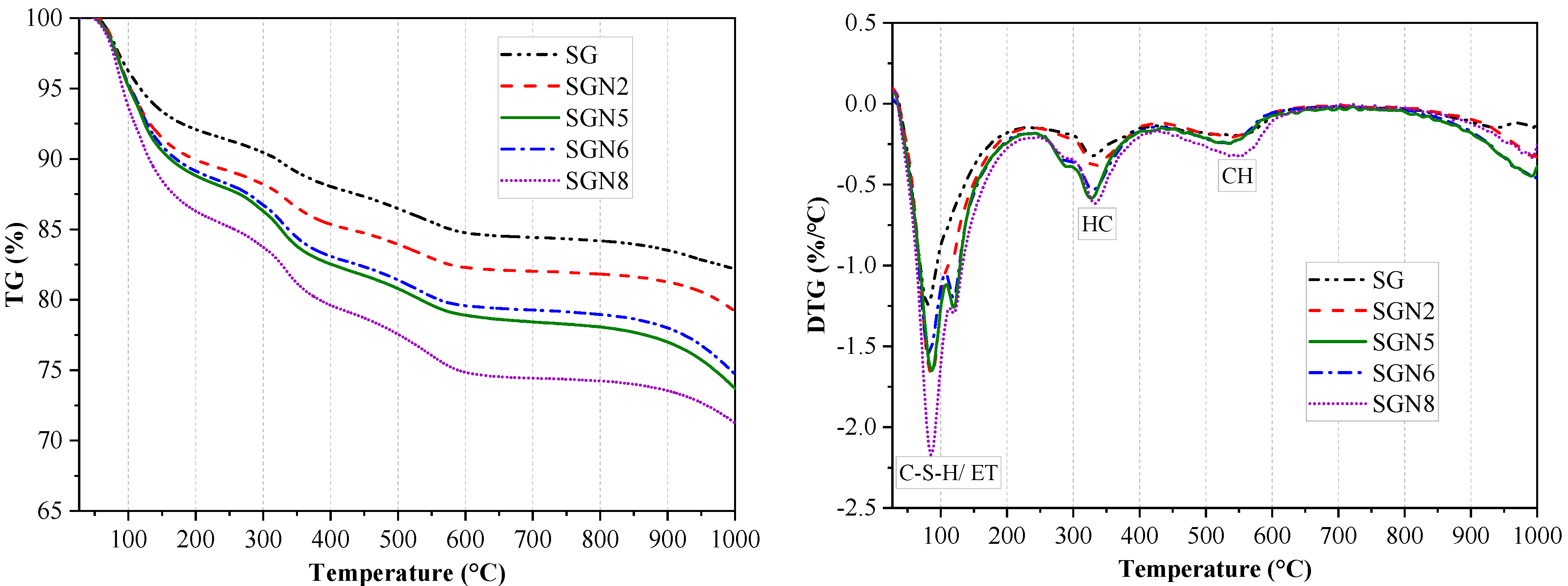
To further determine the composition and evolution patterns of hydration products in binders, TG tests at 28d curing age were conducted for five groups of samples (SG, SGN2, 5, 6, 8). Figure 8 shows the TG-DTG curves obtained in the tests. Figure 9 shows the statistical weight loss results in different temperature ranges.
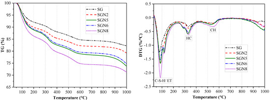
Figure 8.
TG−DTG curves of 28-day samples.
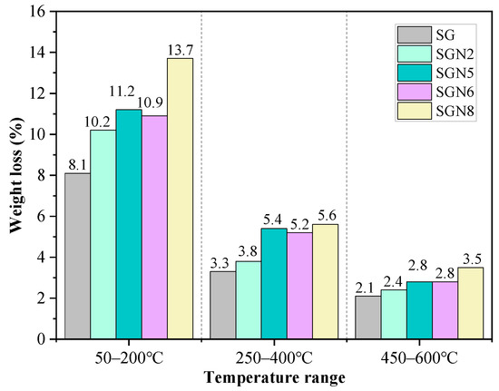
Figure 9.
Weight loss at different temperature ranges for specimens at 28 days.
According to Figure 8, there were mainly three weight loss peaks. The weight loss at 50–200 °C was caused by the dehydration of C-(A)-S-H gel and ET [40,41]. According to a comprehensive analysis of the test results depicted in Figure 9 and XRD examinations, it was revealed that when a 1.0% content of Na2O was added to SG, the intensity of the weight loss peak significantly increased with the weight loss increasing from 8.1 to 10.2%, indicating that the amount of C-(A)-S-H gel produced by hydration was significantly increased. When the content of Na2O was increased to 3.0%, the weight loss further grew to 11.2%. As the amount of ET in the hydration products decreased significantly (Figure 7), the increase of this weight loss was still caused by the significant increase of C-(A)-S-H gel produced by hydration. When the Na2O content was further increased to 4.0%, the weight loss was unchanged, indicating that the excessive alkali content had no obvious effect on C-(A)-S-H gel and ET formation. The intensity of this weight loss peak of SGN8 was the strongest, and the weight loss (13.7%) significantly exceeded that of SGN5, which was mainly caused by the large increase in ET production.
The dehydration and decomposition of HC caused the weight loss at 250–400 °C [14,33]. When 1.0% and 3.0% Na2O were added to SG, the intensity of the weight loss peak increased gradually. The weight loss grew from 3.3% to 3.8% and 5.4%, indicating that the amount of HC in the hydration products increased gradually. When the content of Na2O was increased to 4.0%, the weight loss was unchanged, indicating that excessive alkali contents had no obvious effect on the formation of HC. There was no obvious change in the weight loss of SGN8 compared with SGN5, indicating that the increase of SR content had no obvious effect on the formation of HC crystals. The variation pattern of HC crystals in the TG-DTG test was consistent with that observed via XRD.
The weight loss at 450–600 °C was caused by CH decomposition [29,40]. With the addition of 1.0 and 3.0% Na2O to SG, the weight loss gradually increased from 2.1 to 2.4 and 2.8%, respectively, indicating that the CH crystals in the hydration product gradually increased. However, increasing Na2O content to 4.0% had no obvious effect on the formation of CH because the weight loss remained unchanged. The intensity of this weight loss peak of SGN8 was the strongest, and the weight loss (3.5%) was the largest, indicating that the most CH was generated in the hydration reaction. The variation pattern of CH in the TG-DTG test was consistent with that in XRD.
3.5. FTIR Analysis
Fourier transform infrared spectroscopy (FTIR) provides a useful tool for qualitative and quantitative analysis of hydration products of binders. FTIR tests of 28d samples were conducted on five groups of samples (SG, SGN2, 5, 6, and 8). The test results are plotted in Figure 10.
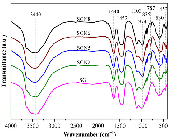
Figure 10.
FTIR curves of 28 d samples.
Ten main absorption peaks can be observed in Figure 10. The absorption peak near 452 cm−1 was caused by the in-plane bending vibration of the Si-O bond. The Si-O bond’s stretching vibration caused the absorption peaks near 797 and 974 cm−1, and the Si-O-Al bond’s deformation vibration caused the absorption peak near 583 cm−1. These four absorption peaks indicate the existence of C-(A)-S-H gel in the hydration products [42,43]. The intensities of these absorption peaks were stronger in SGN5 and SGN6, slightly lower in SGN8, and the lowest in SG and SGN2. The results show that the increased Na2O contents significantly promoted the hydration reaction and C-(A)-S-H gel generation, but the excessive Na2O contents had no obvious promotion effect. Additionally, the increase of SR content was not conducive to C-(A)-S-H gel formation.
The absorption peak near 1103 cm−1 was caused by the stretching vibration of SO42− [44], indicating the existence of ET in the hydration products. The absorption peak intensity was the weakest in SGN5 and SGN6, stronger in SG, SGN2, and the strongest in SGN8, indicating that increased Na2O content did not promote the formation of ET, in contrast to increased SR contents. The out-of-plane bending vibration of CO32−- and the C-O bond’s stretching vibration caused the absorption peaks near 875 and 1452 cm−1 [42,45], respectively, indicating the presence of calcite in these samples [46]. The intensities of these absorption peaks (and thus, the amount of calcite) decreased first and then increased with the Na2O content, which is consistent with the XRD results. Additionally, the higher content of SR in SGN8 led to the highest calcite content and the highest corresponding absorption peak intensity in this sample. The absorption peaks near 1640 cm−1 and 3440 cm−1 were caused by the H-O-H bond’s bending and stretching vibrations, which were the crystal water’s internal vibration absorption characteristics [33,47]. The crystal water mainly came from C-(A)–S-H gel, HC, and ET [33]. The intensities of these two absorption peaks exhibited no obvious patterns related to the large difference in the production of the three hydration products in different groups. The absorption peak near 3641 cm−1 was caused by the vibration of the O-H bond in Ca(OH)2 [48], indicating that there was CH in the hydration products, but the intensity change was not significant. The above results further proved the experimental results of XRD and TG-DTG.
3.6. SEM Analysis
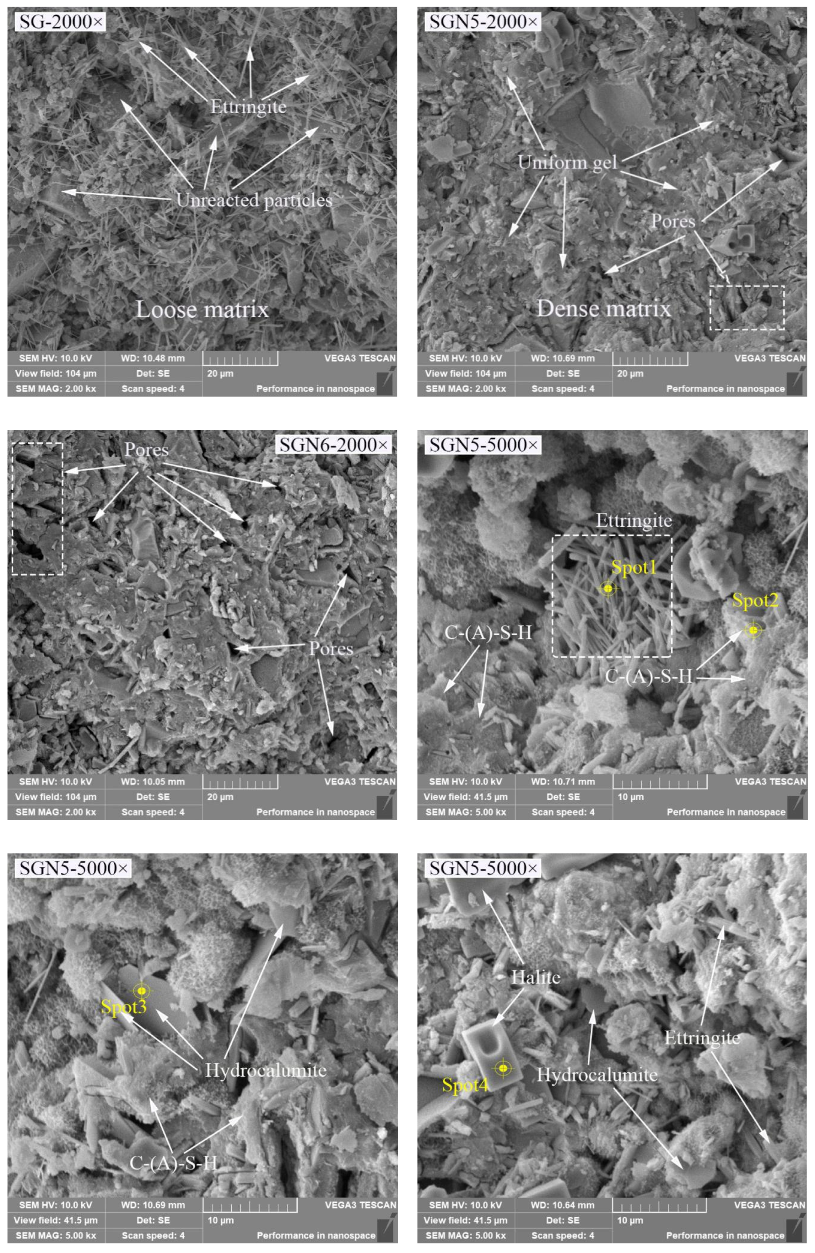
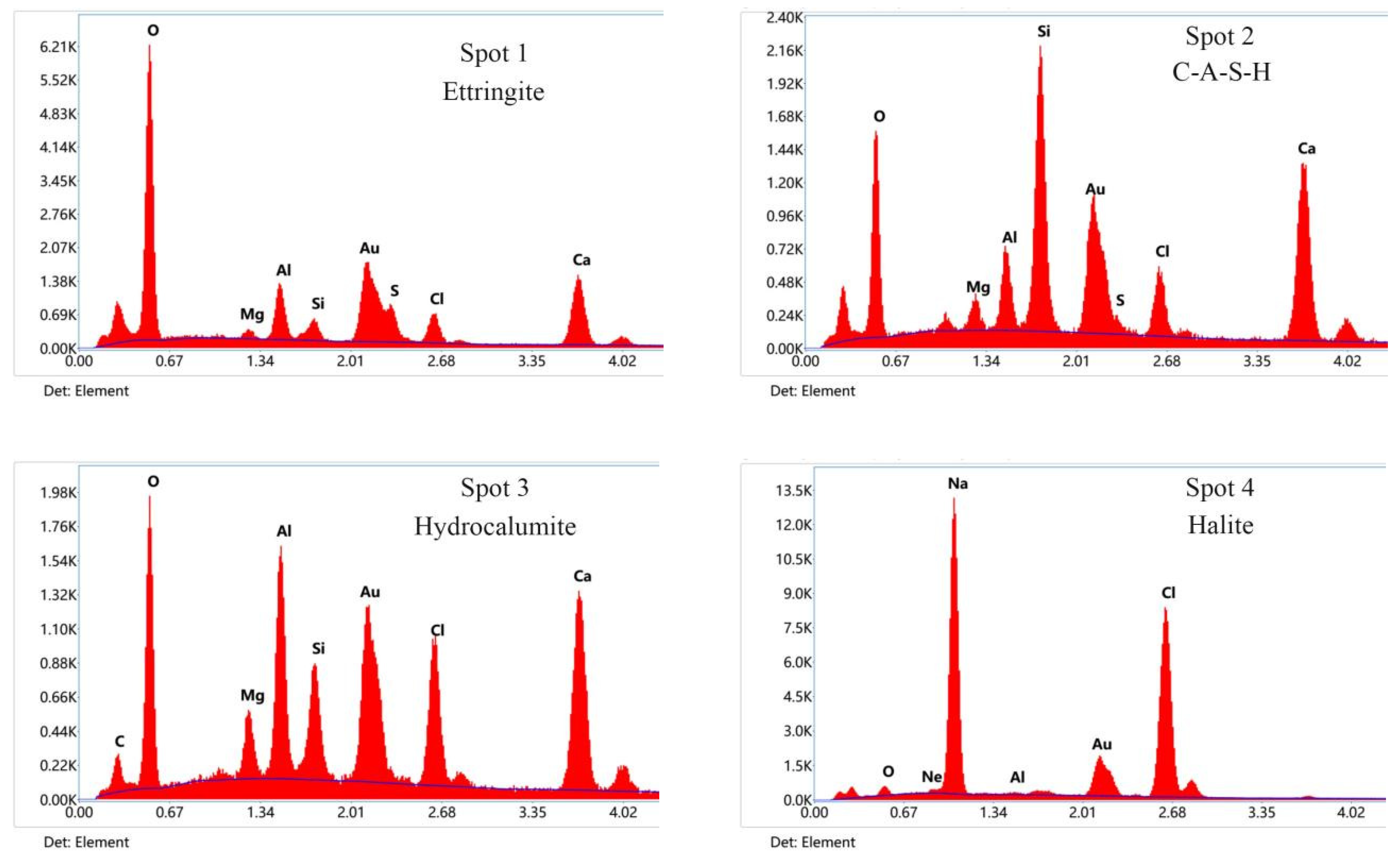
To further determine the hydration products and the micromorphology evolution of the new binders, SEM and EDS tests of SG, SGN5, and SGN6 at the curing age of 28d were conducted. The results are depicted in Figure 11.


Figure 11.
SEM and EDS images of 28d samples.
According to the SEM images of SG, SGN5, and SGN6 samples at a 2000 magnification, the SG’s microstructure was loose, and the continuously distributed gel was scarce. In addition, there were many unreacted raw material particles, and a large amount of ET was generated in the system, which was unfavorable for the later strength development. When 3.0% Na2O was added, the microstructure of SGN5 was significantly improved, more continuously distributed gels could be observed, the number of unreacted raw material particles was significantly reduced, and fewer macropores appeared. Thus, an appropriate amount of NaOH significantly promoted the hydration reaction and significantly improved the compactness. When 4% Na2O was added, the number of macropores in the matrix increased obviously. This might be due to excessive alkalinity resulting in uneven distribution of rapidly generated gel, forming more macropores, which was an important reason for its late strength below SGN5.
The SEM images of the SGN5 sample at a 5000× magnification feature C-(A)-S-H gel, ettringite, hydrocalumite, halite, and other crystals. The ettringite was mainly in a needle-rod form [29,49], the hydrocalumite was mainly in a hexagonal flake form and appeared as irregular flakes when not completely grown [50]. The halite mainly presented as cuboids or cubes. These crystals grew in pores or were interspersed in gels, filling tiny cracks and increasing the structure compactness.
4. Conclusions
In this study, a new alkali-activated SR-BFS composite binder was prepared, and its mechanical properties and microstructure were systematically studied. It can provide solutions to the problems of environmental pollution and land waste caused by the large-scale accumulation of alkali residues. The following conclusions were drawn:
(1) At the SR to BFS ratio of 40:60, the compressive strength increased first and then dropped with the Na2O content. At the optimum Na2O content of 3.0%, the 3d and 28d strength values of 10.5 and 27.8 MPa exceeded those of the control group (without Na2O) by 337.5 and 69.5%, respectively. The compressive strength decreased with increasing SR to BFS ratio and water-binder ratio.
(2) The increased Na2O content reduced the mortar fluidity due to high friction caused by the rapid formation of hydration products promoted by high alkalinity. The high SR contents also reduced the mortar fluidity due to the high water absorption of SR.
(3) The C-(A)-S-H gel, ET, HC, CH, and other crystals were mainly formed in the hydration of the new binder. Increased Na2O contents inhibited the formation of ET but significantly promoted the formation of C-(A)-S-H gel and HC, which was conducive to growth in strength. Excessive alkali contents had no obvious effect on the hydration products. The increased SR content was not conducive to the formation of C-(A)-S-H gel but promoted the formation of ET, which was unfavorable for strength development.
(4) Under the optimal Na2O content, the gel distribution was more uniform, and crystals grew in the pores or interspersed in the gel, filling microcracks and increasing the structure compactness. Excessive Na2O contents could speed up the hydration reaction, but the uneven distribution of rapidly generated gel induced more macropores in the matrix, reducing its strength.
Author Contributions
Data curation, Z.Z. and Z.S.; Formal analysis, Z.S.; Investigation, Z.Z. and D.L.; Methodology, Z.Z.; Project administration, C.X.; Resources, Z.S.; Validation, Z.Z., Z.S. and D.L.; Writing—original draft, Z.Z.; writing—review & editing, C.X. All authors have read and agreed to the published version of the manuscript.
Funding
This research was funded by the National Natural Science Foundation of China under the grant of 21776204.
Acknowledgments
Appreciated the Tangshan Sanyou Alkali Chloride Co., Ltd., for technical consulting, and Tianjin University for academic assist.
Conflicts of Interest
The authors declare no conflict of interest.
References
- Provis, J.L.; Palomo, A.; Shi, C. Advances in understanding alkali-activated materials. Cem. Concr. Res. 2015, 78, 110–125. [Google Scholar] [CrossRef]
- Luukkonen, T.; Abdollahnejad, Z.; Yliniemi, J.; Kinnunen, P.; Illikainen, M. One-part alkali-activated materials: A review. Cem. Concr. Res. 2018, 103, 21–34. [Google Scholar] [CrossRef]
- Purdon, A.O. The action of alkalis on blast-furnace slag. J. Soc. Chem. Ind. 1940, 59, 191–202. [Google Scholar]
- Pacheco-Torgal, F.; Castro-Gomes, J.; Jalali, S. Alkali-activated binders: A review—Part 1. Historical background, terminology, reaction mechanisms and hydration products. Constr. Build. Mater. 2008, 22, 1305–1314. [Google Scholar] [CrossRef]
- de Azevedo, A.R.G. Special edition: Practical applications of durability of activated alkali and geopolymer materials. Case Stud. Constr. Mater. 2022, 17, e01161. [Google Scholar] [CrossRef]
- Zheng, W.; Chen, W.; Wang, Y. High-temperature resistance performance of alkali-activated slag cementitious materials. J. Huazhong Univ. Sci. Technol. 2009, 10, 96–99. [Google Scholar]
- Marvila, M.T.; Azevedo, A.R.G.; Oliveira, L.B.; Xavier, G.C.; Vieira, C.M.F. Mechanical, physical and durability properties of activated alkali cement based on blast furnace slag as a function of Na2O. Case Stud. Constr. Mater. 2021, 15, e00723. [Google Scholar] [CrossRef]
- Asaad, M.A.; Huseien, G.F.; Memon, R.P.; Ghoshal, S.K.; Mohammadhosseini, H.; Alyousef, R. Enduring performance of alkali-activated mortars with metakaolin as granulated blast furnace slag replacement. Case Stud. Constr. Mater. 2022, 16, e00845. [Google Scholar] [CrossRef]
- Islam, A.; Alengaram, U.J.; Jumaat, M.Z.; Bashar, I.I. The development of compressive strength of ground granulated blast furnace slag-palm oil fuel ash-fly ash based geopolymer mortar. Mater. Des. 2014, 56, 833–841. [Google Scholar] [CrossRef]
- Nasir, M.; Johari, M.A.M.; Maslehuddin, M.; Yusuf, M.O.; Al-Harthi, M.A. Influence of heat curing period and temperature on the strength of silico-manganese fume-blast furnace slag-based alkali-activated mortar. Constr. Build. Mater. 2020, 251, 118961. [Google Scholar] [CrossRef]
- Zhao, X.H.; Liu, C.Y.; Wang, L.; Zuo, L.M.; Zhu, Q.; Ma, W. Physical and mechanical properties and micro characteristics of fly ash-based geopolymers incorporating soda residue. Cem. Concr. Compos. 2019, 98, 125–136. [Google Scholar] [CrossRef]
- Song, R.; Zhao, Q.; Zhang, J.; Liu, J. Microstructure and Composition of Hardened Paste of Soda Residue-Slag-Cement Binding Material System. Front. Mater. 2019, 6, 211. [Google Scholar] [CrossRef]
- Zhao, X.; Liu, C.; Zuo, L.; Wang, L.; Zhu, Q.; Liu, Y.; Zhou, B. Synthesis and characterization of fly ash geopolymer paste for goaf backfill: Reuse of soda residue. J. Clean. Prod. 2020, 260, 121045. [Google Scholar] [CrossRef]
- Wang, Q.; Li, J.; Yao, G.; Zhu, X.; Arulrajah, A.; Hu, S.; Qiu, J.; Chen, P.; Lyu, X. Characterization of the mechanical properties and microcosmic mechanism of Portland cement prepared with soda residue. Constr. Build. Mater. 2020, 241, 117994. [Google Scholar] [CrossRef]
- Bai, X.; Ma, J.; Liu, J.; Zhang, M.; Yan, N.; Wang, Y. Field experimental investigation on filling the soda residue soil with liquid soda residue and liquid fly ash. Int. J. Damage Mech. 2020, 30, 502–517. [Google Scholar] [CrossRef]
- Ma, J.; Yan, N.; Zhang, M.; Liu, J.; Bai, X.; Wang, Y. Mechanical Characteristics of Soda Residue Soil Incorporating Different Admixture: Reuse of Soda Residue. Sustainability 2020, 12, 5852. [Google Scholar] [CrossRef]
- Yan, Y.; Sun, X.; Ma, F.; Li, J.; Shen, J.; Han, W.; Liu, X.; Wang, L. Removal of phosphate from wastewater using alkaline residue. J. Environ. Sci. 2014, 26, 970–980. [Google Scholar] [CrossRef]
- Ucal, G.O.; Mahyar, M.; Tokyay, M. Hydration of alinite cement produced from soda waste sludge. Constr. Build. Mater. 2018, 164, 178–184. [Google Scholar] [CrossRef]
- Liu, J.Z.; Zhao, Q.X.; Zhang, J.R.; An, S. Microstructure and composition of hardened paste of soda residue-slag complex binding materials. J. Build. Mater. 2019, 22, 872–877. [Google Scholar]
- Lin, Y.H.; Xu, D.Q.; Zhao, X.H. Experimental research on mechanical property and microstructure of blast furnace slag cementitious materials activated by soda residue. Bull. Chin. Ceram. Soc. 2019, 38, 2876–2881. [Google Scholar]
- Guo, W.; Zhang, Z.; Bai, Y.; Zhao, G.; Sang, Z.; Zhao, Q. Development and characterization of a new multi-strength level binder system using soda residue-carbide slag as composite activator. Constr. Build. Mater. 2021, 291, 123367. [Google Scholar] [CrossRef]
- Guo, W.; Wang, S.; Xu, Z.; Zhang, Z.; Zhang, C.; Bai, Y.; Zhao, Q. Mechanical performance and microstructure improvement of soda residue-carbide slag-ground granulated blast furnace slag binder by optimizing its preparation process and curing method. Constr. Build. Mater. 2021, 302, 124403. [Google Scholar] [CrossRef]
- Li, J.; Zhang, S.; Wang, Q.; Ni, W.; Li, Z. Feasibility of using fly ash–slag-based binder for mine backfilling and its associated leaching risks. J. Hazard. Mater. 2020, 400, 123191. [Google Scholar] [CrossRef]
- Guo, W.; Zhang, Z.; Zhao, Q.; Song, R.; Liu, J. Mechanical properties and microstructure of binding material using slag-fly ash synergistically activated by wet-basis soda residue-carbide slag. Constr. Build. Mater. 2021, 269, 121301. [Google Scholar] [CrossRef]
- GB/T 17671; Method of Testing Cements -Determination of Strength (ISO method). Standards Press of China: Beijing, China, 1999.
- GB/T 2419; Test Method for Fluidity of Cement Mortar. Standards Press of China: Beijing, China, 2005.
- Zhang, J.; Scherer, G.W. Comparison of methods for arresting hydration of cement. Cem. Concr. Res. 2011, 41, 1024–1036. [Google Scholar] [CrossRef]
- Jiao, Z.Z.; Wang, Y.; Zheng, W.Z.; Huang, W.X. Effect of dosage of sodium carbonate on the strength and drying shrinkage of sodium hydroxide based alkali-activated slag paste. Constr. Build. Mater. 2018, 179, 11–24. [Google Scholar] [CrossRef]
- Li, W.; Yi, Y. Use of carbide slag from acetylene industry for activation of ground granulated blast-furnace slag. Constr. Build. Mater. 2020, 238, 117713. [Google Scholar] [CrossRef]
- Zheng, W.; Zou, M.; Wang, Y. Literature review of alkali-activated cementitious materials. J. Build. Struct. 2019, 40, 28–39. [Google Scholar]
- Salih, M.A.; Farzadnia, N.; Ali, A.A.; Demirboga, R. Effect of different curing temperatures on alkali activated palm oil fuel ash paste. Constr. Build. Mater. 2015, 94, 116–125. [Google Scholar] [CrossRef]
- Lin, Y.; Xu, D.; Zhao, X. Properties and hydration mechanism of soda residue-activated ground granulated blast furnace slag cementitious materials. Materials 2021, 14, 2883. [Google Scholar] [CrossRef]
- Xu, D.; Ni, W.; Wang, Q.; Xu, C.; Jiang, Y. Preparation of clinker-free concrete by using soda residue composite cementitious material. J. Harbin Inst. Technol. 2020, 52, 151–160. [Google Scholar]
- Jiao, Z.Z.; Wang, Y.; Zheng, W.Z.; Huang, W.X. Effect of the activator on the performance of alkali-activated slag mortars with pottery sand as fine aggregate. Constr. Build. Mater. 2019, 197, 83–90. [Google Scholar] [CrossRef]
- Wang, W.C.; Wang, H.Y.; Lo, M.H. The fresh and engineering properties of alkali activated slag as a function of fly ash replacement and alkali concentration. Constr. Build. Mater. 2015, 84, 224–229. [Google Scholar] [CrossRef]
- Taylor, H.; Famy, C.; Scrivener, K. Delayed ettringite formation. Cem. Concr. Res. 2001, 31, 683–693. [Google Scholar] [CrossRef]
- Tian, X.; Xu, W.Y.; Song, S.X.; Rao, F.; Xia, L. Effects of curing temperature on the compressive strength and microstructure of copper tailing-based geopolymers. Chemosphere 2020, 253, 126754. [Google Scholar] [CrossRef]
- Phoo-Ngernkham, T.; Phiangphimai, C.; Intarabut, D.; Hanjitsuwan, S.; Damrongwiriyanupap, N.; Li, L.-Y.; Chindaprasirt, P. Low cost and sustainable repair material made from alkali-activated high-calcium fly ash with calcium carbide residue. Constr. Build. Mater. 2020, 247, 118543. [Google Scholar] [CrossRef]
- Han, F.; Liu, R.; Yan, P. Influence of slag on microstructure of complex binder pastes. J. Chin. Electron Microsc. Soc. 2014, 33, 40–45. [Google Scholar]
- Zhang, J.; Tan, H.; He, X.; Yang, W.; Deng, X. Utilization of carbide slag-granulated blast furnace slag system by wet grinding as low carbon cementitious materials. Constr. Build. Mater. 2020, 249, 118763. [Google Scholar] [CrossRef]
- Park, H.; Jeong, Y.; Jun, Y.; Jeong, K.-H.; Oh, J.E. Strength enhancement and poresize refifinement in clinker-free CaO-activated GGBFS systems through substitution with gypsum. Cem. Concr. Compos. 2016, 68, 57–65. [Google Scholar] [CrossRef]
- Ping, Y.; Kirkpatrick, R.J.; Poe, B.; Mcmillan, P.F.; Cong, X. Structure of Calcium Silicate Hydrate (C-S-H): Near-, Mid-, and Far-Infrared Spectroscopy. J. Am. Ceram. Soc. 2010, 82, 742–748. [Google Scholar]
- Mollah, M.Y.A.; Yu, W.; Schennach, R.; Cocke, D.L. A Fourier transform infrared spectroscopic investigation of the early hydration of Portland cement and the influence of sodium lignosulfonate. Cem. Concr. Res. 2000, 30, 267–273. [Google Scholar] [CrossRef]
- Ghosh, S.N.; Handoo, S.K. Infrared and Raman spectral studies in cement and concrete (review). Cem. Concr. Res. 1980, 10, 771–782. [Google Scholar] [CrossRef]
- Lodeiro, I.G.; Macphee, D.E.; Palomo, A.; Fernández-Jiménez, A. Effect of alkalis on fresh C–S–H gels. FTIR analysis. Cem. Concr. Res. 2009, 39, 147–153. [Google Scholar] [CrossRef]
- Fernandez, L.; Alonso, C.; Hidalgo, A.; Andrade, C. The role of magnesium during the hydration of C3S and CSH formation. Scanning electron microscopy and mid-infrared studies. Adv. Cem. Res. 2005, 17, 9–21. [Google Scholar] [CrossRef]
- Zhang, Y.; Sun, W.; Jia, Y.; Jin, Z. Composition and structure of hardened geopolymer products using infrared ray analysis methods. J. Wuhan Univ. Technol. 2005, 27, 31–34. [Google Scholar]
- Puertas, F.; Palacios, M.; Manzano, H.; Dolado, J.; Rico, A.; Rodríguez, J. A model for the CASH gel formed in alkali-activated slag cements. J. Eur. Ceram. Soc. 2011, 31, 2043–2056. [Google Scholar] [CrossRef]
- Zhang, Y.; Liu, X.; Xu, Y.; Tang, B.; Wang, Y.; Mukiza, E. Synergic effects of electrolytic manganese residue-red mud-carbide slag on the road base strength and durability properties. Constr. Build. Mater. 2019, 220, 364–374. [Google Scholar]
- Liu, C.B.; Ji, H.G.; Liu, J.H.; He, W.; Gao, C. Experimental study on slag composite cementitious material for solidifying coastal saline soil. J. Build. Mater. 2015, 18, 82–87. [Google Scholar]


Publisher’s Note: MDPI stays neutral with regard to jurisdictional claims in published maps and institutional affiliations. |
© 2022 by the authors. Licensee MDPI, Basel, Switzerland. This article is an open access article distributed under the terms and conditions of the Creative Commons Attribution (CC BY) license (https://creativecommons.org/licenses/by/4.0/).