Article

An Investigation of Opportunity Charging with Hybrid Energy Storage System on Electric Bus with Two-Speed Transmission

National Engineering Research Center of Electric Vehicles, Beijing Institute of Technology, Beijing 100081, China
*
Author to whom correspondence should be addressed.
Sustainability 2022, 14(19), 11918; https://doi.org/10.3390/su141911918
Submission received: 18 July 2022 / Revised: 4 September 2022 / Accepted: 16 September 2022 / Published: 21 September 2022
(This article belongs to the Special Issue Hybrid Energy System in Electric Vehicles)

Abstract

:
As one of the most popular and important forms of massive transit, the public bus contributes to a healthier environment compared to private vehicles. Through the electrification of the public bus, energy consumption, carbon emission, and air pollution can be significantly reduced. However, the limited driving range and high battery replacement cost put significant barriers to its large-scale commercialization. Thanks to the development of wireless charging technology and opportunity charging strategy, the driving range can be improved. However, the battery has to suffer additional impulse current generated by opportunity wireless charging. In this paper, a hybrid energy storage system (HESS) that combines battery and supercapacitor and related energy control strategy is proposed to smoothen the impulse current and extend the battery lifespan. A comprehensive investigation of the combined impacts of the opportunity charging and HESS is carried out in terms of driving range extension and battery lifespan improvement. The detailed HESS model and powertrain model are built. A global optimizing method, dynamic programming, is adopted as the energy management strategy under the Chinese heavy-duty commercial vehicle test cycle-bus (CHTC-B). A battery degradation model is employed to evaluate its health with 60 kW wireless charging. The results demonstrate that the proposed energy control strategy for HESS could improve battery health and extend bus driving range concurrently via opportunity charging.

1. Introduction

The transportation sector is one of the major contributors to greenhouse emissions (GHE) and air pollution. It accounts for 29% of total GHG emissions in the USA [1] and 45% of the particulate matter pollution in Beijing [2]. Since the diesel engine-powered public bus is the major contributor to transportation pollutant emissions, including SO2, SO3, PM2.5, NOX, CO, VOC, etc. [3] Replacing conventional diesel buses with new energy vehicles, such as electric buses, would reduce the local GHE significantly at a reasonable cost [4]. As a consequence, many cities in China, e.g., Beijing, Shen Zhen, and Hang Zhou have announced their plan to use electric buses to replace internal combustion buses. Since public buses generally have a higher usage hour compared to private cars, batteries in electrified public buses require a larger capacity and are charged more frequently. However, the performance of electrochemical batteries decays with increasing charging cycles [5]. Furthermore, frequent start-stop of running cycles with considerable vehicle mass require relative high-power discharging/charging currents, which leads to a faster decay rate [6]. Compared to the electrochemical battery, the supercapacitor (SC) shows higher power density with far fewer sensitivities to charging cycles and time regarding capacity degradation, though its low energy density blocks the possibility to be the sole energy storage system in electric vehicles (EVs).
Hence, combining battery and SC into a hybrid energy storage system (HESS) will both benefit from the high-energy density of the battery and the high power density& long lifespan of SC at the same time. SC works as a ‘power buffer’ to absorb or release impulse current which is caused by instantaneous accelerating or regenerative braking. However, private EVs are very sensitive to price and have less chance of exposure to frequent impulse current [7], the high cost [8] and low utilization of SC put significant barriers to large-scale commercialization of HESS. Besides its capacity degradation and high cost, the replacement of safety issue of battery packs attracts significant attention as there are many serious fire accidents caused by its inherent thermal runaway. With the increasing requirement of driving range per charge, which is usually up to 200 km for public EVs in China, car manufacturers need to put more battery packs and guarantee a longer warranty period for a battery. Under such circumstances, a HESS system comprising EB and SC is a more suitable option for public EVs without significant additional cost while minimizing the degradation of battery lifespan [9].
Compared to private EVs, public EVs have a much heavier mass and load burden, and the required charging energy is significantly higher. Although adding more battery packs possibly can extend the driving range, the extra weight and cost inevitably offset its benefit. Therefore, the better solution is to periodically supplement energy to the vehicle rather than simply increase onboard energy capacity. Meanwhile, wireless power transfer (WPT) technology for EVs has been developed and attracted great attention recently. As the physical plug-in process is eliminated in WPT, the charging process could start within milliseconds and enjoy flexibility in charging site selection [10]. Hence, a practical application of WPT in public EVs should rely on opportunity charging technology, which installs the primary charging pad under the bus parking areas/bus stops and recharges them when passengers are getting on and off [11]. For public buses, the opportunity charging process is supposed to be done in a short period since the time for picking up passengers is usually less than 1 min. To charge as much energy as possible, the charging device should be capable of transferring energy with a relatively high power, which may cause a significant impulse to the onboard energy storage system. Therefore, HESS could be a suitable option for EV opportunity charging to protect the battery from fast aging. The HESS for heavy duty and fuel cell electric vehicles is investigated in [12,13].
The Utah State University [14] and Korea Advanced Institute of Science and Technology (KAIST) [15] both developed high power dynamic WPT for EVs, which could recharge the EV during its operation. However, the dynamic power transfer requires an extremely high construction cost compared to that of the opportunity charging as the power transmission track has to be buried under the road. The lifecycle optimization of EV wireless charger deployment is presented in [16], and the lifecycle cost of wireless charger and GHG emission is considered as the optimization objects. In [17], the design of battery and SC in a HESS for EVs are optimized considering the size, cost, and driving range, however, the impact of the opportunity charging was not considered. The opportunity charging for a battery EV is discussed in [10] where the driving range extension was estimated with urban driving cycles, while the impact of the powertrain system and HESS was not included. The advantages of technologies are scenario-based, therefore it is important to investigate the overall system performance by building a model based on a practical bus and product.
HESS, WPT, and opportunity charging are promising technologies for future EVs, which offer a satisfactory driving range with rational cost. Unfortunately, to the best knowledge of the authors, a comprehensive investigation of the combined applications of the above three key technologies in an electric bus is missing, not to mention the complicated mutual effects of each cutting-edge technology.
The contribution of the paper is as follows:
(1)
The combination of the HESS and WPT and the two-speed transmission system is investigated. The collaboration between the systems is analyzed in detail;
(2)
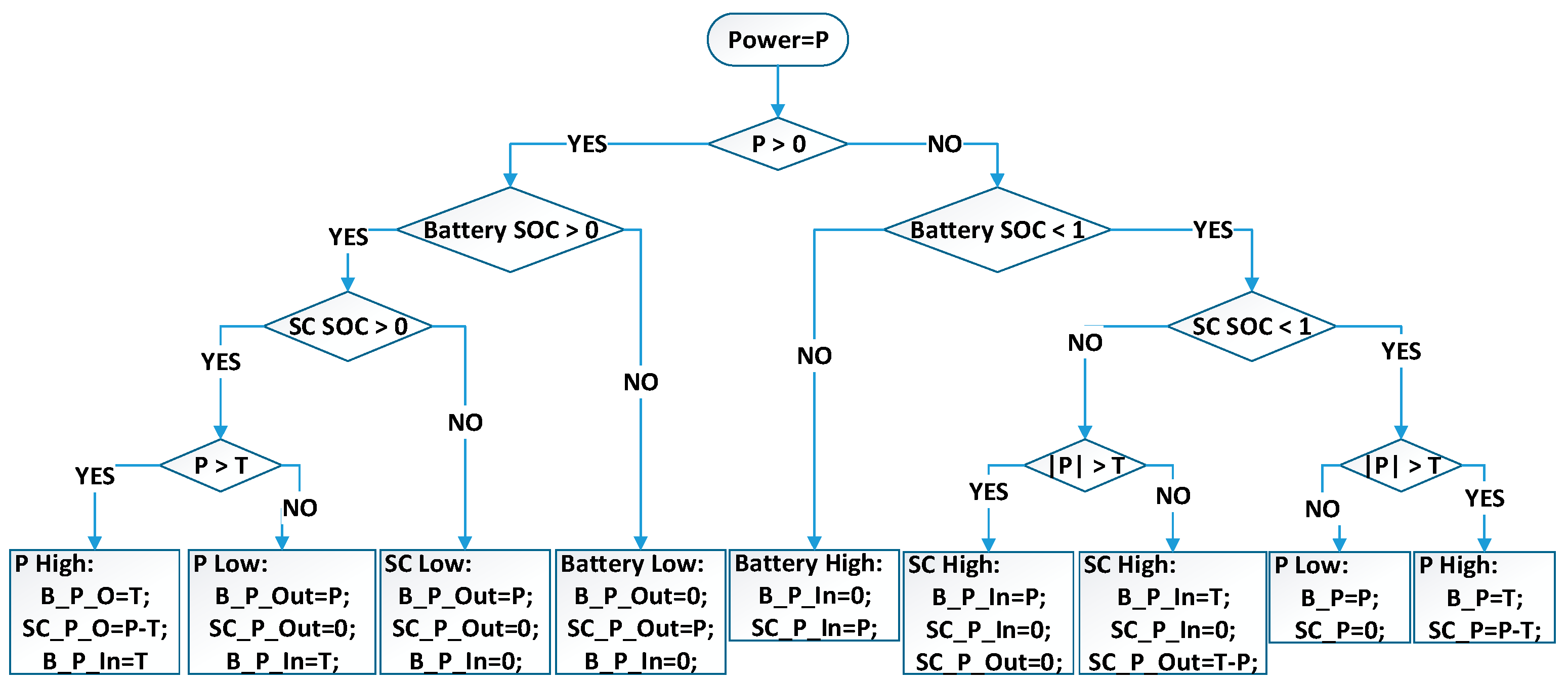
A power flow control strategy is proposed, where the battery health protection and range extension are considered;
(3)
As a practical bus powertrain model and driving cycle are employed, the analysis result would be a good reference for industry application.
Therefore, in this paper, the combined implementation of opportunity WPT and HESS for EVs has been investigated in terms of battery health improvement and driving range extension. First, an electric bus powertrain model is built and China heavy-duty commercial vehicle test cycle-bus (CHTC-B) is employed for the analysis. Then, the driving range extension by opportunity charging is demonstrated and verified in CHTC-B. Next, the battery health improvement is evaluated through a Lithium-ion battery decay model. Finally, conclusions are summarized with a comprehensive analysis of the findings in this study.

2. Wireless Charging System for Electric Bus

The public buses generally travel on regular routes and stop at fixed spots where the opportunity charging could be implemented and buses could pick up power from it. To supplement energy to a vehicle within a limited stop time, the power rating of the opportunity charging is supposed to be high.
SIEMENS developed a top-down pantograph-based opportunity charging system for electric buses with three power ratings: 150, 300, and 450 kW [18]. With the mechanical pantograph, the EVs could be recharged at the stop where these charging facilities are available, however, there are conductors in the open air with high voltage, which may lead to possible safety issues.
Wireless charging offers an alternative way for EV opportunity charging. It uses a high-frequency electromagnetic field to transfer power across the air gap. The electromagnetic field could be established within a millisecond, therefore, power transfer could be started and stopped without affecting the running of the bus.

2.1. Wireless Charging System

The general structure of the wireless charging system is shown in Figure 1.
The AC power from the grid is rectified into DC and then inverted into high-frequency (HF) current for the coupler. The power is transferred across the air gap from the primary side of the coupler to the secondary side through the electromagnetic field. To enhance the power transfer capacity, compensation circuits are added for both the primary and secondary sides of the coupler. The received high-frequency power is rectified into DC to recharge the onboard batteries.

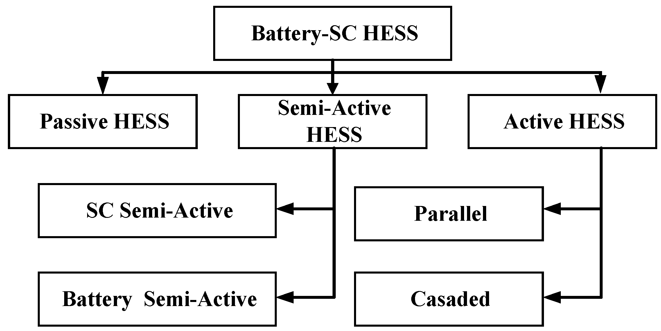
2.2. Hybrid Energy Storage Electric Bus

The most widely used energy storage for vehicular applications is electrochemical batteries, such as lithium-ion and nickel-metal hydride. Both of them offer a high energy density, but a poor power density and relatively short lifespan compared to other major components such as SC. For the duty cycle with frequent acceleration and braking, the battery cannot absorb full regenerative braking power. Therefore, the power from braking regeneration cannot be fully used and overall energy efficiency would be affected. The opportunity charging generally is active after the vehicle deceleration during which the braking regeneration is employed. The high-power charging would also aggravate the degradation of the battery. SC has a higher power density and a longer lifecycle. SC can absorb regenerative and opportunity charging power, however, due to the limitation in energy density, the SC energy storage system does not satisfy the energy consumption required for continuous running without quick charging. For an energy system of the same size, the HESS which combines battery and SC has higher energy and peak power, while it can balance the needs of energy and power.
There are several types of HESS topologies, such as passive topology, semi-active topology, and active topology, as shown in Figure 2. The passive topology could not utilize the SOC of SC as it is directly connected to the DC bus without a converter. As the voltage of SC is limited by battery voltage, the variation of SC’s SOC is limited.
An active HESS control strategy is employed in this paper as shown in Figure 3. The active topology has a bidirectional DC/DC converter for both battery and SC. The regenerated power could be distributed between the battery and SC. The power output of the WPT is connected with the DC bus of the active HESS, therefore, the power could be distributed between the battery and SC by controlling the bidirectional converters.

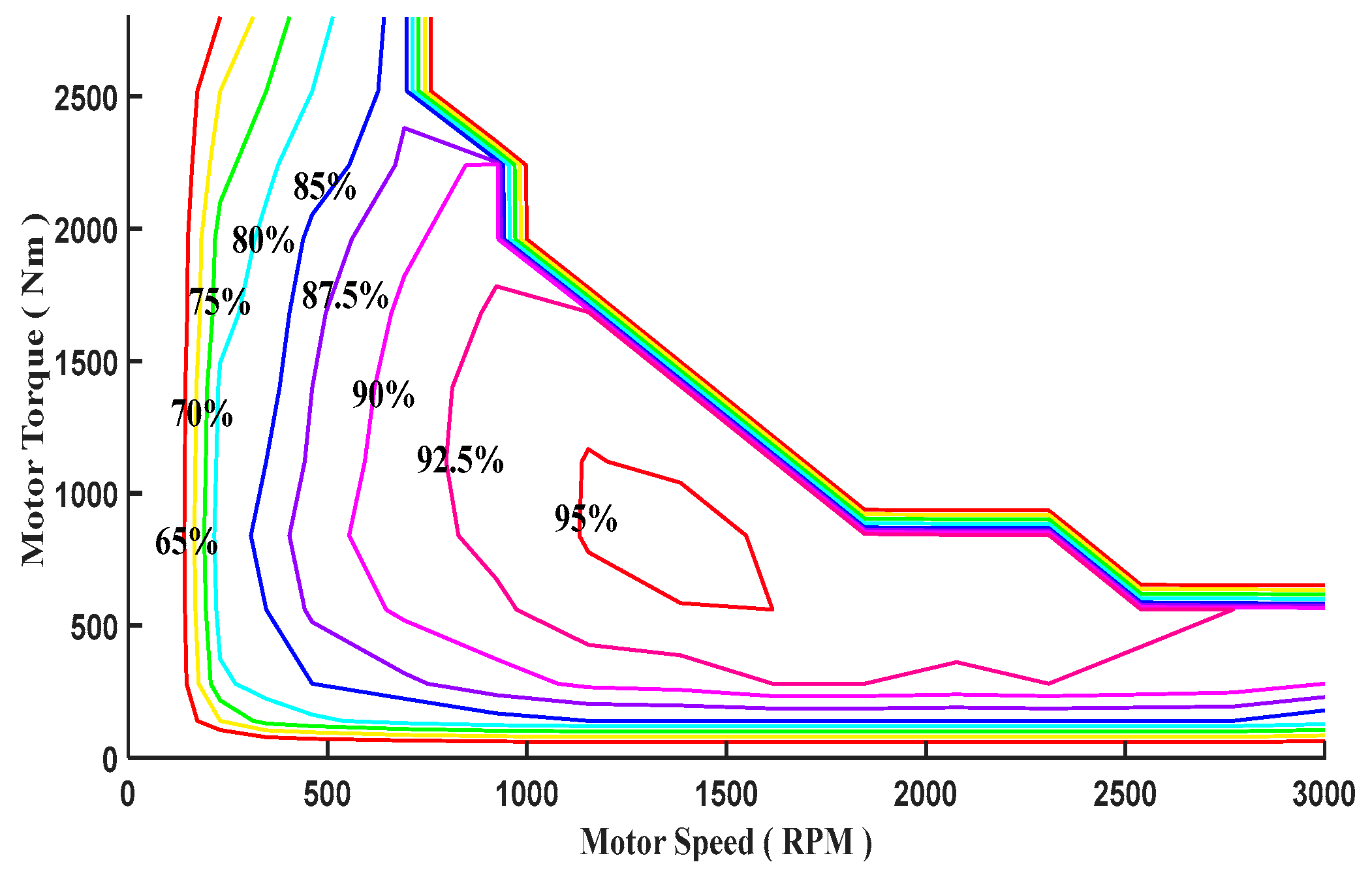
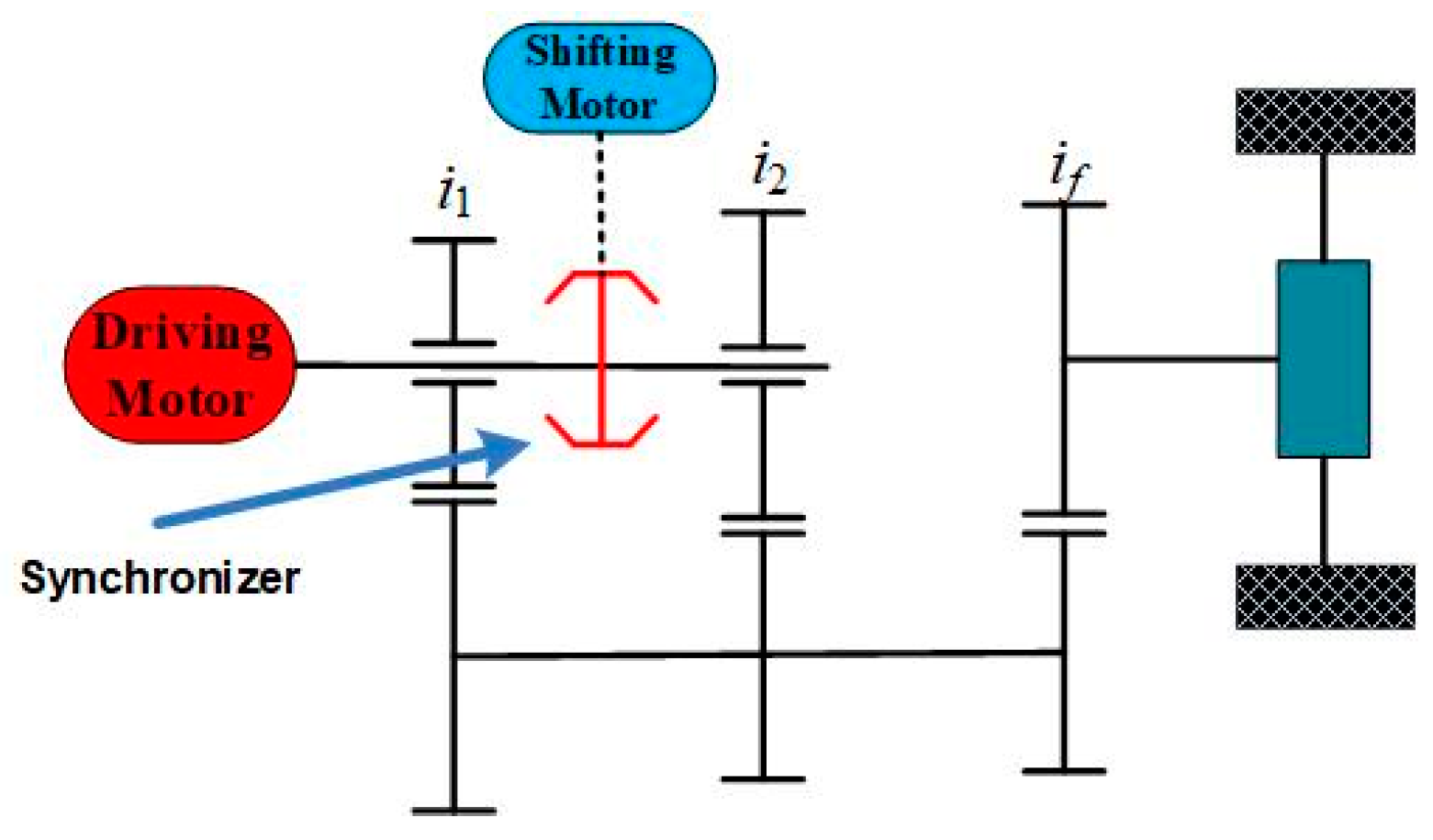
2.3. Multi-Speed Transmission

Single-speed transmission, i.e., speed reducer, is popular and dominant in the EV market. In contrast, the alternative multi-speed transmissions attract great attention as they can significantly boost the motor operating efficiency, ultimately, improving overall powertrain efficiency [19]. There are plural studies on structures, control methods, and shifting strategies for EV-based multi-speed transmission [20,21,22,23]. For example, an automatic transmission (AT) was customized by involving two brakes to balance shifting quality, vehicle dynamics, and fuel economy for BEVs [24]. To compare the performance of a multi-speed EV powertrain with different gear numbers, the 4-speed transmission was proposed and optimized to investigate the overall system efficiency [25]. As the ultimate solution in terms of increasing gear number to improve motor efficiency, half toroidal Variable Transmissions (CVTs) and electrified full toroidal CVTs were specially designed for EV [26,27]. Regarding the control strategy of the proposed multi-speed transmission for EV, various optimal gear-shifting control strategies were proposed to improve the performance of conventional transmission on EV [23,28,29]. Most of the mentioned multi-speed transmission systems still rely on a hydraulic system, which is an auxiliary system and benefits from the constant pressure generated by the drive engine. However, the hydraulic system turns into a burden to the motor since the motor runs from time to time when necessary, which leads to the requirement of an additional pump to generate constant pressure.
In this paper, an electrified two-speed automatic manual transmission is proposed considering the cost, control complexity, driving experience, and application background. Furthermore, a hybrid energy storage system with the opportunity for wireless charging is implemented in a benchmarking electric bus to replace the conventional battery & cable charging system. A comprehensive investigation of the proposed powertrain will be carried out in the following sections, followed by a conclusion at last.

3. The Powertrain Model

A market-ready battery-electric public bus is selected as the benchmark with specifications in Table 1. The battery energy storage system is replaced by a hybrid energy storage system that combines battery and SC.
The China heavy-duty commercial vehicle test cycle-bus (CHTC-B) is employed in this study [30]. This driving cycle is specially designed for heavy-duty public buses which weigh over 3500 kg and operate in metropolitan areas. This cycle comprises two-speed zones, i.e., a low-speed zone accounting for 30.5% and a high-speed zone accounting for 69.5% of the total time, which together make up a 5.49 km cycle range. The driving cycle is shown in Figure 4.
The CHTC-B is slightly modified to form six stops, i.e.,199–215 s, 357–399 s, 589–604 s, 823–838 s, 1020–1038 s,1279–1319 s, which can be used for opportunity charging. The EV is propelled by a permanent magnet synchronous motor, which has 2800 Nm peak torque and 3000 RPM maximum rotational speed. The efficiency map of the adopted motor is shown in Figure 5.

3.1. Battery Degradation Model

Both opportunity wireless charging and regeneration braking could generate ads impulse current and damage the energy storage system. By adopting HESS, battery State of Charge (SoC) can be stabilized, and ultimately, the battery life span can be extended. To evaluate the performance of HESS in improving battery degradation, a semi-empirical battery degradation model [31] is applied in the model, which is based on the Arrhenius degradation model and determined by four parameters:
Qloss = Ae^{−[(Ea + B × CRate)/(RTbat)]}(Ah)^z
where Qloss represents the capacity loss of battery, A stands for pre-exponential factor, the air constant 8.314 J/mol/K−1 is represented by R in this equation, Tbat is the absolute temperature (K), CRate stands for the discharging rate of the battery, the activation energy, 78.06 (J), is represented by Ea, Ah is the Ah-throughput, z is a time factor, and B is a compensation factor for CRate.
In this study, this capacity fade model of the LiFePO4 battery is adopted to investigate the battery dynamic degradation based on cumulative damage theory. The equation of the dynamic degradation discrete model can be expressed as:
Q loss , p + 1 Q loss , p = Δ A h zA 1 z e ( E a + B × C Rate RT bat ) Q loss , p z 1 z
where Qloss,p+1 and Qloss,p are the accumulated battery capacity loss at t (p + 1) and tp, ∆Ah stands for the A h-throughput from tp to t (p + 1), which can be expressed as:
Δ A h = 1 3600 t p t p + 1 | I bat |
Then, through experimental verification, the above function is simplified [32] and the parameters were calibrated as shown in
Q loss = 0.0032 e ( 15162 1516 C Rate RT bat ) ( A h ) 0.824
This section may be divided into subheadings. It should provide a concise and precise description of the experimental results, their interpretation, as well as the experimental conclusions that can be drawn.

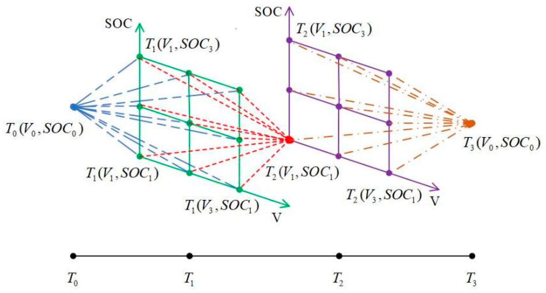
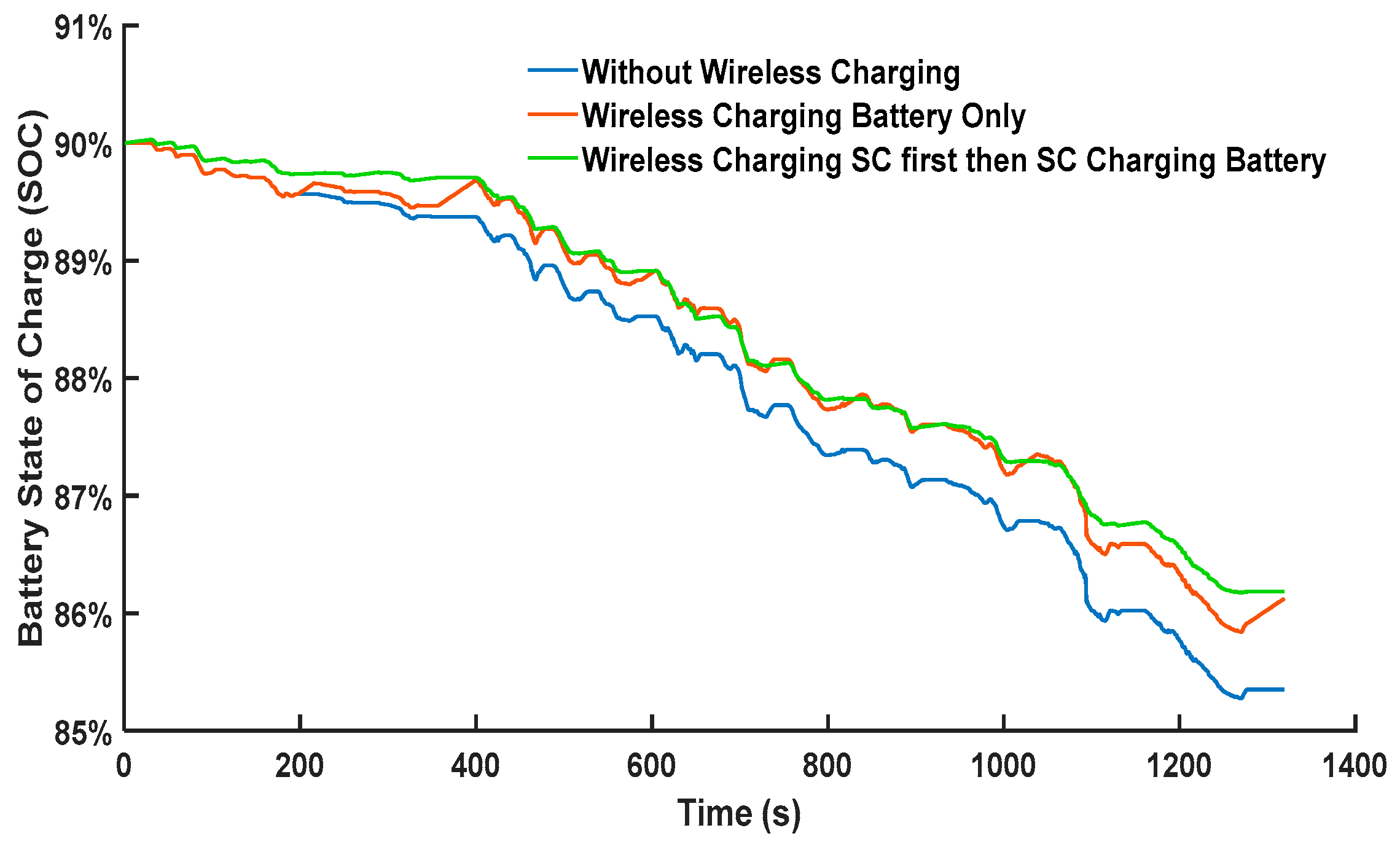
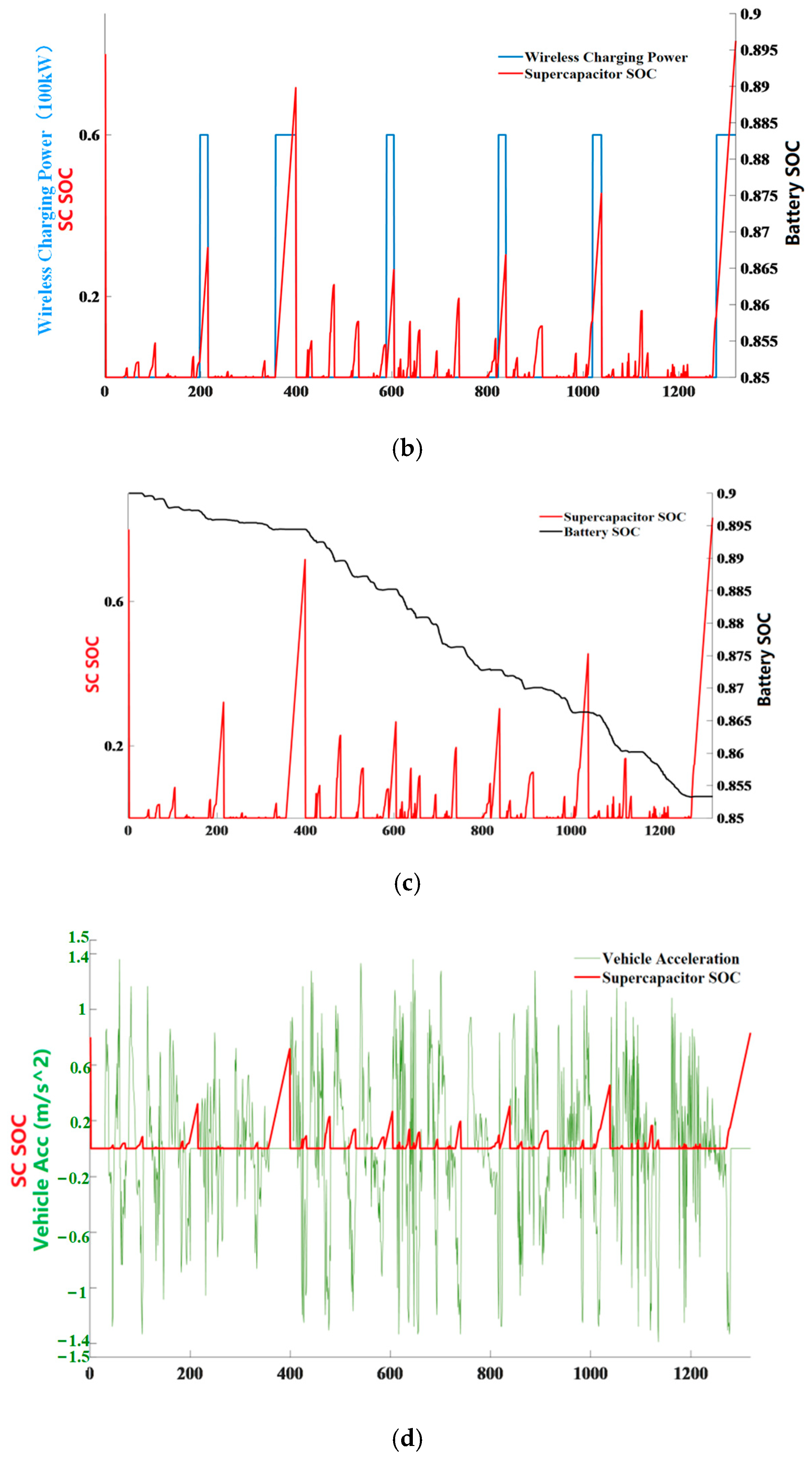
3.2. The Energy Management Strategy of the Hybrid Energy Storage System with Opportunity Wireless Charging

To evaluate the most beneficial potential of HESS on opportunity wireless charging based EV in terms of battery health improvement, a global optimizing method, Dynamic Programming (DP), is adopted for CHTC-B.
Although the requirement of routing information in advance excludes the possibility of practical use, the DP-based results present the most potential to support other practical battery degradation reduction methods, which can be used in online applications, e.g., Rule-Based, via using SC more efficiently. Given that battery voltage variation is normally less than 1 V, it is taken as constant during the whole cycle to simplify the calculation with satisfying precision. In each time period k, the accumulated SC power P S C , t o t a l can be derived by [32]:
P S C , t o t a l ( k , j , i ) = 0.5 C S C T s ( V S C ( k , j ) 2 V S C ( k 1 , i ) 2 )  
The capacity loss of battery at any time period k is expressed by the following cost function:
{ J b a t , l o s s ( k ) = | I b a t ( k ) | T S 3600 Z A 1 Z e ( E a + B × C R a t e ( k ) z R T b a t ) Q l o s s ( k 1 ) z 1 z M i n i m i z e { k = 1 k = k m a x J b a t , l o s s ( k ) }
Sample time T S is set to 1 s to relieve the computational burden, and J b a t , l o s s ( k ) stands for the system cost, which can be derived through Equations (4)–(7), which presents the capacity loss from k − 1 to k. The initial voltage of SC, represented as V SC , initial , is set to 0.9 V SC , max in all DP processes. Figure 6 schematically presents the process of searching for the optimal solution by DP for above process from T0 to T3. The topology of the energy management strategy is shown in Figure 7. During the brake regeneration and WPT stage, electric power goes to the HESS system. The power flows to the SC and then the battery. During the bus acceleration or running stage, the energy from SC is used first, followed by that from the battery.

3.3. Two-Speed Automatic Transmission

Considering the enormous load, driving comfort requirement, and manufacturing cost, a motor-assisted electrified two-speed automated manual transmission (AMT), as shown in Figure 8, is proposed in this paper. The synchronizer is controlled by a motor, rather than a conventional hydraulic system, to realize the shift between 1st (left) and 2nd gear (right). Since an electrified powertrain does not need to keep constant pressure to maintain the hydraulic system running, unlike an internal combustion engine, the exclusion of a hydraulic system in an EV will effectively boost the overall powertrain efficiency.

4. Results Analysis

The Performance of Multi-Speed Transmission in Terms of Powertrain Efficiency

The extra gear keeps the motor from extreme working conditions and low-efficiency zones and increases the possibility of working in high-efficiency zone for the motor. As shown in Figure 9, the blue circle mark stands for the motor operating tracks of a single-speed transmission-based powertrain while the red star marks represent the motor tracks with 2-speed AMT over the motor efficiency map.
Compared to the single-speed one, the 2-speed AMT assisted motor tracks to avoid the low-efficiency & high-speed zone and work closer to the high-efficiency area. The lifespan of the motor also benefits from the relatively low working speed. An average 7% improvement is recorded in CHTC-B through the adoption of 2-speed AMT. The performance of HESS and the opportunity for wireless charging
It has been known that SC can work as a ‘buffer’ to reduce the negative effect of ‘impulse’ current on battery health, nevertheless, wireless charging provides a similar function to a hybrid energy storage system in terms of keeping the battery from large-current charging/discharging. Compared to fast cable charging, opportunity wireless charging transfers the same amount of energy from the grid to the vehicle in a longer period with a relatively low current. However, compared to directly charging the battery transferring energy to SC first, then, SC to the battery is a better option in terms of battery health. Based on the battery degradation model in Section 2.1, the improvement of battery capacity loss per CHTC-B cycle is shown in Figure 10.
Regarding the energy consumption of the battery, there is no doubt that energy from the opportunity charging system eliminates part of the energy depleted from the battery. However, adoption of HESS or not shows different patterns of behavior. Although the final battery energy consumption of HESS and battery-only-based powertrain are almost the same (little different from the SC capacity), the fluctuation of HESS-based battery energy consumption is relatively low, as shown in the green curve in Figure 11, compared to battery-only one, shown in red curve. The reason is that the opportunity for wireless charging powertrain transfers energy to SC first, then, SC gradually transfers to the battery at a low power rate, while energy transfers directly from the grid to the battery at a high-power rate in the battery-only powertrain.
The dynamic performance of the system is shown in Figure 12. As can be seen from Figure 12a, the WPT system is enabled when the bus is at the bus stop from which a 60 kW power is transferred. The transferred power is charged to the SC, and the SC is capable to store the WPT power. When the bus leaves the bus stop, the energy in SC is consumed by the acceleration, as can show in Figure 12b at 400 s. The SOC of the SC and battery, during the driving cycle, are shown in Figure 12c. The SOC of the battery kept decreasing, and the SOC of the SC varies with the acceleration of the bus as shown in Figure 12d.
To quantify the performance of HESS and opportunity charging, Table 2 summarizes the energy consumption per CHTC-B cycle, the driving range, and related extension between wireless and cable chargers in a unit of CHTC-B cycle.
As shown in Table 2, compared to the bus operation scenario without wireless charging, the energy transferred from the grid by wireless opportunity charging can save 1.27 kWh onboard energy per CHTC-B cycle while HESS can help the electric bus further save 0.11 kWh. In other words, 16.7% (1.27/7.67) of the required energy per CHTC-B cycle can be provided by wireless charging. Then, HESS can help wireless charging transfer an additional 1.7% (0.11/6.4) of electricity to the EV. Assuming the SOC of the EV is not allowed to lower than 10%, each powertrain configuration-based EV can finish 19, 23, and 23 CHTC-B cycles, respectively. In other words, with the help of opportunity wireless charging, the EV can run extra 4 cycles.
Given the distance of the CHTC-B cycle is 5.49 km, the energy consumption per 100 km of each powertrain configuration can be expressed as:
{ E c a b l e = 7.67 × 100 ÷ 5.45 = 140.7   kWh E w i r e l e s s = 6.4 × 100 ÷ 5.45 = 117.4   kWh E w i r e l e s s + H E S S = 6.29 × 100 ÷ 5.45 = 115.4   kWh  
Compared to the cable fast charging strategy, opportunity wireless charging not only saves the battery energy but also extends battery lifespan through a gentler charging current, compared to fast charging by cable at a bus station. Take cable fast charging as an example, it can charge the battery from empty to 100% in 1.5 h, which results in 1.3 Wh capacity loss per charge.
According to Equation (7), fast cable charging from empty to full will leads to a 1.3 Wh battery capacity loss. Therefore, the capacity loss per CHTC-B cycle for the non-wireless charging strategy consists of loss from battery discharging and each cycle share of full cable charging (1.3 Wh/19), which is shown in Table 3.

5. Conclusions

A hybrid energy storage system with an opportunity wireless charging strategy is proposed for a 2-speed EV in this study. The 2-speed automated manual transmission effectively boosts the overall powertrain efficiency by 7% through moving motor tracks to a higher efficiency zone, compared to a single-speed EV powertrain. The opportunity wireless charging, which is implemented during six stops of CHTC-B in this study, gives the EV another 4 CHTC-B cycles between two cable charging, which equals to 21.96 km driving range extension. By adding SC to the conventional battery to make up a hybrid energy storage system, the negative effect of impulse current during wireless charging can be further reduced. Specifically, 14% improvement has been achieved by wireless charging in terms of battery capacity degradation, and a further 7% improvement is made by the HESS through the charging strategy, i.e., grid-SC battery. To sum up, the effectiveness of the proposed control strategy for HESS and the opportunity of wireless charging on improving battery health and extend driving range per charge have been verified. The combination of a 2-speed AMT, HESS, and opportunity wireless charging system is a suitable powertrain configuration for EVs.

Author Contributions

Conceptualization, Y.Y. and S.W.; methodology, Z.W.; software, Y.Y.; validation, Y.Y and S.W.; formal analysis, Y.Y.; investigation, S.W.; resources, Y.Y.; data curation, Y.Y.; writing—original draft preparation, Y.Y.; writing—review and editing, N.L. and S.W.; visualization, Y.Y.; supervision, Z.W. and S.W.; project administration, N.L.; funding acquisition, N.L. All authors have read and agreed to the published version of the manuscript.

Funding

This research was funded by the National Key Research and Development Program of China under Grant 2021YFB2501600.

Institutional Review Board Statement

Not applicable.

Informed Consent Statement

Not applicable.

Data Availability Statement

Not applicable.

Conflicts of Interest

The authors declare no conflict of interest.

References

  1. United States Environmental Protection Agency. Fast Facts: U.S. Transportation Sector GHG Emissions 2019; US EPA: Washington, DC, USA, 2019.
  2. Beijing Municipal Ecology and Environment Bureau. 2018. Available online: http://sthjj.beijing.gov.cn/bjhrb/index/xxgk69/zfxxgk43/qtfdxx73/zfxxgknb13/1721232/index.html (accessed on 15 September 2022).
  3. Aber, J. Electric Bus Analysis for New York City Transit; Columbia University: New York, NY, USA, 2016; 37p, Available online: http://www.columbia.edu/~ja3041/Electric%20Bus%20Analysis%20for%20NYC%20Transit%20by%20J%20Aber%20Columbia%20University%20-%20May%202016.pdf (accessed on 15 September 2022).
  4. Song, Q.; Wang, Z.; Wu, Y.; Li, J.; Yu, D.; Duan, H.; Yuan, W. Could urban electric public bus really reduce the GHG emissions: A case study in Macau? J. Clean. Prod. 2018, 172, 2133–2142. [Google Scholar] [CrossRef]
  5. Shibagaki, T.; Merla, Y.; Offer, G.J. Tracking degradation in lithium iron phosphate batteries using differential thermal voltammetry. J. Power Sources 2018, 374, 188–195. [Google Scholar] [CrossRef]
  6. Abdel-Monem, M.; Trad, K.; Omar, N.; Hegazy, O.; Bossche, P.V.D.; Van Mierlo, J. Influence analysis of static and dynamic fast-charging current profiles on ageing performance of commercial lithium-ion batteries. Energy 2017, 120, 179–191. [Google Scholar] [CrossRef]
  7. BYD Auto Co. Research of Battery Durability Performance; BYD Auto Co.: Shenzhen, China, 2013. [Google Scholar]
  8. Burke, A.; Liu, Z.; Zhao, H. Present and future applications of supercapacitors in electric and hybrid vehicles. In Proceedings of the 2014 IEEE International Electric Vehicle Conference (IEVC), Florence, Italy, 17–19 December 2014; pp. 1–8. [Google Scholar] [CrossRef]
  9. Du, J.; Zhang, X.; Wang, T.; Song, Z.; Yang, X.; Wang, H.; Ouyang, M.; Wu, X. Battery degradation minimization oriented energy management strategy for plug-in hybrid electric bus with multi-energy storage system. Energy 2018, 165, 153–163. [Google Scholar] [CrossRef]
  10. Bi, Z.; Song, L.; De Kleine, R.; Mi, C.; Keoleian, G.A. Plug-in vs. wireless charging: Life cycle energy and greenhouse gas emissions for an electric bus system. Appl. Energy 2015, 146, 11–19. [Google Scholar] [CrossRef]
  11. Lukic, S.; Pantic, Z. Cutting the Cord: Static and Dynamic Inductive Wireless Charging of Electric Vehicles. IEEE Electrif. Mag. 2013, 1, 57–64. [Google Scholar] [CrossRef]
  12. Li, W.; Cui, H.; Nemeth, T.; Jansen, J.; Ünlübayir, C.; Wei, Z.; Zhang, L.; Wang, Z.; Ruan, J.; Dai, H.; et al. Deep reinforcement learning-based energy management of hybrid battery systems in electric vehicles. J. Energy Storage 2021, 36, 102355. [Google Scholar] [CrossRef]
  13. Ruan, J.; Zhang, B.; Liu, B.; Wang, S. The multi-objective optimization of cost, energy consumption and battery degradation for fuel cell-battery hybrid electric vehicle. In Proceedings of the 2021 11th International Conference on Power, Energy and Electrical Engineering (CPEEE), Shiga, Japan, 26–28 February 2021; pp. 50–55. [Google Scholar] [CrossRef]
  14. Azad, A.; Saha, T.; Zane, R.; Pantic, Z. Design of hybrid energy storage systems for wirelessly charged electric vehicles. In Proceedings of the 2015 IEEE 82nd Vehicular Technology Conference (VTC2015-Fall), Boston, MA, USA, 6–9 September 2015; pp. 1–5. [Google Scholar] [CrossRef]
  15. Choi, S.Y.; Gu, B.W.; Jeong, S.Y.; Rim, C.T. Advances in Wireless Power Transfer Systems for Roadway-Powered Electric Vehicles. IEEE J. Emerg. Sel. Top. Power Electron. 2015, 3, 18–36. [Google Scholar] [CrossRef]
  16. Bi, Z.; Keoleian, G.A.; Ersal, T. Wireless charger deployment for an electric bus network: A multi-objective life cycle optimization. Appl. Energy 2018, 225, 1090–1101. [Google Scholar] [CrossRef]
  17. Ruan, J.; Walker, P.D.; Zhang, N.; Wu, J. An investigation of hybrid energy storage system in multi-speed electric vehicle. Energy 2017, 140, 291–306. [Google Scholar] [CrossRef]
  18. Siemens. eBus Charging Infrastructure; Siemens Mobil: Munich, Germany, 2016; pp. 1–17. [Google Scholar]
  19. Ruan, J.; Walker, P.; Wu, J.; Zhang, N.; Zhang, B. Development of continuously variable transmission and multi-speed dual-clutch transmission for pure electric vehicle. Adv. Mech. Eng. 2018, 10, 1687814018758223. [Google Scholar] [CrossRef]
  20. Qin, D.-T.; Yao, M.-Y.; Chen, S.-J.; Lyu, S.-K. Shifting process control for two-speed automated mechanical transmission of pure electric vehicles. Int. J. Precis. Eng. Manuf. 2016, 17, 623–629. [Google Scholar] [CrossRef]
  21. Ruan, J.; Walker, P.; Zhang, N. A comparative study energy consumption and costs of battery electric vehicle transmissions. Appl. Energy 2016, 165, 119–134. [Google Scholar] [CrossRef]
  22. Wu, J.; Walker, P.D.; Ruan, J.; Zhang, N. Target torque estimation for gearshift in dual clutch transmission with uncertain parameters. Appl. Math. Model. 2017, 51, 1–20. [Google Scholar] [CrossRef]
  23. Tian, Y.; Ruan, J.; Zhang, N.; Wu, J.; Walker, P. Modelling and control of a novel two-speed transmission for electric vehicles. Mech. Mach. Theory 2018, 127, 13–32. [Google Scholar] [CrossRef]
  24. Mousavi, M.S.R.; Pakniyat, A.; Wang, T.; Boulet, B. Seamless dual brake transmission for electric vehicles: Design, control and experiment. Mech. Mach. Theory 2015, 94, 96–118. [Google Scholar] [CrossRef]
  25. Ren, Q.; Crolla, D.A.; Morris, A. Effect of transmission design on Electric Vehicle (EV) performance. In Proceedings of the 2009 IEEE Vehicle Power and Propulsion Conference, Dearborn, MI, USA, 7–10 September 2009; pp. 1260–1265. [Google Scholar] [CrossRef] [Green Version]
  26. Verbelen, F.; Druant, J.; Derammelaere, S.; Vansompel, H.; De Belie, F.; Stockman, K.; Sergeant, P. Benchmarking the permanent magnet electrical variable transmission against the half toroidal continuously variable transmission. Mech. Mach. Theory 2017, 113, 141–157. [Google Scholar] [CrossRef]
  27. Ruan, J.; Song, Q.; Yang, W. The application of hybrid energy storage system with electrified continuously variable transmission in battery electric vehicle. Energy 2019, 183, 315–330. [Google Scholar] [CrossRef]
  28. Roozegar, M.; Angeles, J. The optimal gear-shifting for a multi-speed transmission system for electric vehicles. Mech. Mach. Theory 2017, 116, 1–13. [Google Scholar] [CrossRef]
  29. Zhu, B.; Zhang, N.; Walker, P.; Zhan, W.; Zhou, X.; Ruan, J. Two-Speed DCT Electric Powertrain Shifting Control and Rig Testing. Adv. Mech. Eng. 2013, 5, 323917. [Google Scholar] [CrossRef]
  30. GB/T38146.2-2019; China Automotive Test Cycle—Part 2: Heavy-Duty Commercial Vehicles. China National Standardization Administration: Beijing, China, 2019.
  31. Zhou, X.; Qin, D.; Hu, J. Multi-objective optimization design and performance evaluation for plug-in hybrid electric vehicle powertrains. Appl. Energy 2017, 208, 1608–1625. [Google Scholar] [CrossRef]
  32. Song, Z.; Hofmann, H.; Li, J.; Han, X.; Ouyang, M. Optimization for a hybrid energy storage system in electric vehicles using dynamic programing approach. Appl. Energy 2015, 139, 151–162. [Google Scholar] [CrossRef]
Figure 1. The general structure of EV Wireless Charging System.
Sustainability 14 11918 g001
Figure 2. Popular hybrid energy storage system topologies.
Sustainability 14 11918 g002
Figure 3. An Active HESS Topology for Electric Bus.
Sustainability 14 11918 g003
Figure 4. China heavy-duty commercial vehicle test cycle-bus.
Sustainability 14 11918 g004
Figure 5. Motor Efficiency Map.
Sustainability 14 11918 g005
Figure 6. Arc costs in DP flow-chart example. The points are the state values; the lines out of each point represent the control choices, and arrows to the next state value are selected by applying DP control.
Sustainability 14 11918 g006
Figure 7. Schematic topology of energy management strategy.
Sustainability 14 11918 g007
Figure 8. Schematic diagram of electrified two-speed AMT.
Sustainability 14 11918 g008
Figure 9. Motor operating tracks of 2-speed and 1-speed based powertrain in CHTC-B.
Sustainability 14 11918 g009
Figure 10. Battery capacity loss per CHTC-B cycle in Wh.
Sustainability 14 11918 g010
Figure 11. Energy consumption comparison of different charging strategies with/without wireless charging.
Sustainability 14 11918 g011
Figure 12. Energy and power variation with vehicle speed in HESS (a) Wireless Charging Power vs. SC SOC vs. Battery SOC vs. Vehicle Acc; (b) Wireless Charging Power vs. SC SOC; (c) Wireless Charging Power vs. Battery SOC; (d) Vehicle ACC vs. SC SOC.
Sustainability 14 11918 g012aSustainability 14 11918 g012b
Table 1. Specifications of Benchmark Battery Electric Bus.
Vehicle Mass17,600 kgMax. Speed 70 km/h
Battery Pack Capacity165 kWhBattery Pack Voltage570 V
Motor Max. Torque2800 NTyre Radius0.57 m
Motor Max Speed3000 RPMFrontal Area8 m2
Motor Peak Power200 kWGear Ratio9.75
Charging Time (Cable)1.5 hSC capacity0.8 kWh
Table 2. Comparison between Different Topologies in terms of Energy Saving.
Energy Consumption per CHTC-BCycles per Cable Charge *Driving Range/Cycles Extension per Cable Charge *
No wireless charging7.67 kWh19.36 ≈ 19---
Wireless Charging Battery6.40 kWh23.2 ≈ 2321.96 km ≈ 4 CHTC-B cycles
Wireless Charging SC, then, to Battery6.29 kWh23.6 ≈ 2321.96 km ≈ 4 CHTC-B cycles
* Battery must be charged by cable before SOC reaches 10% left.
Table 3. Battery Capacity loss of Various Powertrain Configurations.
Battery Capacity Loss per CHTC-BImprovementImprovement
Fast Cable Charging0.50 Wh------
Wireless Charging Battery0.43 Wh14%---
Wireless Charging SC, then to Battery0.40 Wh20%7%
Publisher’s Note: MDPI stays neutral with regard to jurisdictional claims in published maps and institutional affiliations.

