Article

Study on Anti-Uplift Effect of Micro-Steel-Pipe Pile on Red-Bedded Soft Rock Subgrade

1
School of Traffic & Transportation Engineering, Changsha University of Science & Technology, Changsha 410114, China
2
National Engineering Research Center of Highway Maintenance Technology, Changsha University of Science & Technology, Changsha 410114, China
3
Hunan Communications Research Institute Co., Ltd., Changsha 410075, China
4
MOE Key Laboratory of Engineering Structures of Heavy-Haul Railway, Central South University, Changsha 410075, China
*
Author to whom correspondence should be addressed.
Sustainability 2022, 14(19), 11923; https://doi.org/10.3390/su141911923
Submission received: 9 August 2022 / Revised: 18 September 2022 / Accepted: 19 September 2022 / Published: 21 September 2022

Abstract

:
To investigate the treatment effect of micro-piles on uplift deformation of red-bedded soft rock subgrade, an in-situ static load test of slurry injected steel pipe micro-piles with different length was carried out, the uplift bearing capacity and deformation characteristics of micro-piles were analyzed, and the load transfer function of pile lateral friction resistance was modified with the consideration of pile length. A numerical simulation method considering the variable shear stiffness at the pile-soil interface was established, and the inversion of the relevant material parameters was carried out based on the in-situ test results. Through numerical simulation, the effect of single piles with different pile lengths and group piles with different pile spacing on the treatment of the uplift deformation of the subgrade was investigated. Finally, the anti-uplift design method of micro-piles in red-bedded soft rock was proposed. The results show that the uplift bearing capacity increased nonlinearly with the increase in pile length, and the variation curve of pile lateral friction resistance with pile-soil relative displacement showed a hardened type. The predicted pile lateral friction resistance shows a good correlation with the measured result; all the correlation coefficients were greater than 0.81. The uplift deformation of subgrade without piles was radially distributed with the maximum value of 5.12 mm as the center. A single micro-pile with a length of 7 m or a rectangular array of group piles with a length of 7 m and a spacing of 3D could effectively decrease the maximum uplift deformation to less than 4.0 mm, which can meet the requirement of specification. Thus, the micro-piles could be used for controlling the uplift deformation of red-bedded soft rock subgrade, and this study can provide a reference for anti-uplift design in the distributed area of red-bedded soft rock.

1. Introduction

Red-bedded soft rock is a brick-red, red, or brownish-red rock mass mainly cemented by mud, which was formed in the Cretaceous, Jurassic and Tertiary Periods, and is widely distributed in China [1]. The saturated uniaxial compressive strength of red-bedded soft rock is generally less than 5 MPa, belonging to the category of extremely soft rock to soft rock, with bad engineering properties such as easy weathering, easy softening and disintegration in water, micro-expansion, low strength, and large compressibility [2,3,4,5,6,7]. As the scale of China’s transportation infrastructure construction continues to expand, the engineering problems associated with red-bedded soft rocks are increasing, such as heave of foundation [8], uplift of tunnel floor [9,10] and the swell of high-speed railway subgrade, which have all been reported repeatedly [11,12], causing a large number of economic losses. Micro-pile is a sort of bored reinforced grouting pile, and has been widely used in ground and foundation reinforcement, emergency rescue and repair, and prevention of uneven settlement in subgrade [13,14,15]. Compared with conventional pile, micro-pile has smaller diameter that generally refers to pile diameter less than 300 mm, and it has advantages such as relatively low vibration and noise, fast construction speed, less cost, as well as a flexible pile arrangement during construction process. Furthermore, it can also be constructed in limited construction sites when large machines are not applicable [16,17]. However, its application in red-bedded soft rock foundation reinforcement has rarely been reported, and its feasibility needs to be further studied. Furthermore, as an extremely strict requirement for the allowable deformation of ballastless track of China high-speed railway is stated as only 4.0 mm [12,18,19], controlling the subgrade heave has become an urgent engineering problem in the construction of high-speed railway in red-bedded soft rock areas. The construction side for the treatment of uneven subgrade heave is relatively small, and it is necessary to ensure the train operation, hence, there is a need to limit disturbance of adjacent subgrade during the reinforcement process. Therefore, it is of great theoretical and practical significance to study the anti-uplift characteristics of micro-piles in red-bedded soft rock subgrade and reveal their anti-uplift characteristics for the design of micro-piles in red-bedded soft rock areas.
At present, more studies have been conducted on the deformation mechanism of the uplift of red-bedded soft rock subgrade, and it is generally believed that the deformation is caused by excavation unloading [12,20,21] and expansion [22,23,24,25]. However, the research on the treatment measures for the heave of the red-bedded soft rock subgrade is still relatively recent, and the pile-slab structure is generally used to span or avoid the heave area of the subgrade [26,27,28,29]. In terms of micro-pile foundation treatment, Lee et al. revealed the enhancement mechanism of the diameter, length, and number of micro-piles on the bearing capacity of the foundation through model tests [30]. Kyung and Lee [31,32] investigated the uplift bearing characteristics of inclined micro-single piles and group piles by indoor sand model test, and found that the uplift force decreases with the uplift displacement and increases with the pile embedment angle, and proposed the distribution ratio of axial and lateral loads. Ying et al. [33] investigated the correlation between borehole diameter and vertical displacement, radial displacement, and earth pressure on the surface of mixed limestone and soil foundations, and found that borehole diameter was positively correlated with displacement and earth pressure. Gupta and Chawla [34] investigated the effect of micro-pile diameter, length, spacing and inclination angle on the reinforcement of railway subgrade by numerical simulation and concluded that micro-pile is an effective method for reinforcing the existing railway track. Zekavati et al. [35] carried out in-situ pullout tests on micro-piles, and analyzed the sensitivity of parameters such as pile diameter, pile spacing and shear strength on the pullout load capacity of single and group piles by numerical simulation based on the test results. In general, the current research on micro-piles is mostly focused on the reinforcement treatment of soil foundation, but there is less research on the treatment of red-bedded soft rock foundation, and the effect of micro-piles on the treatment of red-bedded soft rock heave and its action mechanism still need to be further clarified.
In this paper, an in-situ static load test was firstly carried out on grouting steel pipe micro-piles in red-bedded soft rock foundation, and the distribution of uplift bearing capacity and uplift displacement along the pile body with different pile lengths were investigated. Secondly, considering the influence of pile lengths, the load transfer function of pile lateral friction resistance was modified, and the prediction method of pile lateral friction resistance considering the influence of pile length was also proposed. Thirdly, the simulation of pile-soil contact shear stiffness was realized by finite element calculation software from the relationship between the measured pile-soil relative displacement and the lateral friction resistance. On this basis, the inversion of the relevant material parameters was carried out by numerical simulation. Finally, the numerical calculation of the subgrade uplift deformation under the conditions of no pile, single pile and group piles in red-bedded soft rock subgrade was carried out, the effect of micro-piles against uplift of red-bedded soft rock was investigated, and the anti-uplift design method of micro-pile in red-bedded soft rock was proposed.

2. Field Test on Uplift Behavior of Micro-Piles

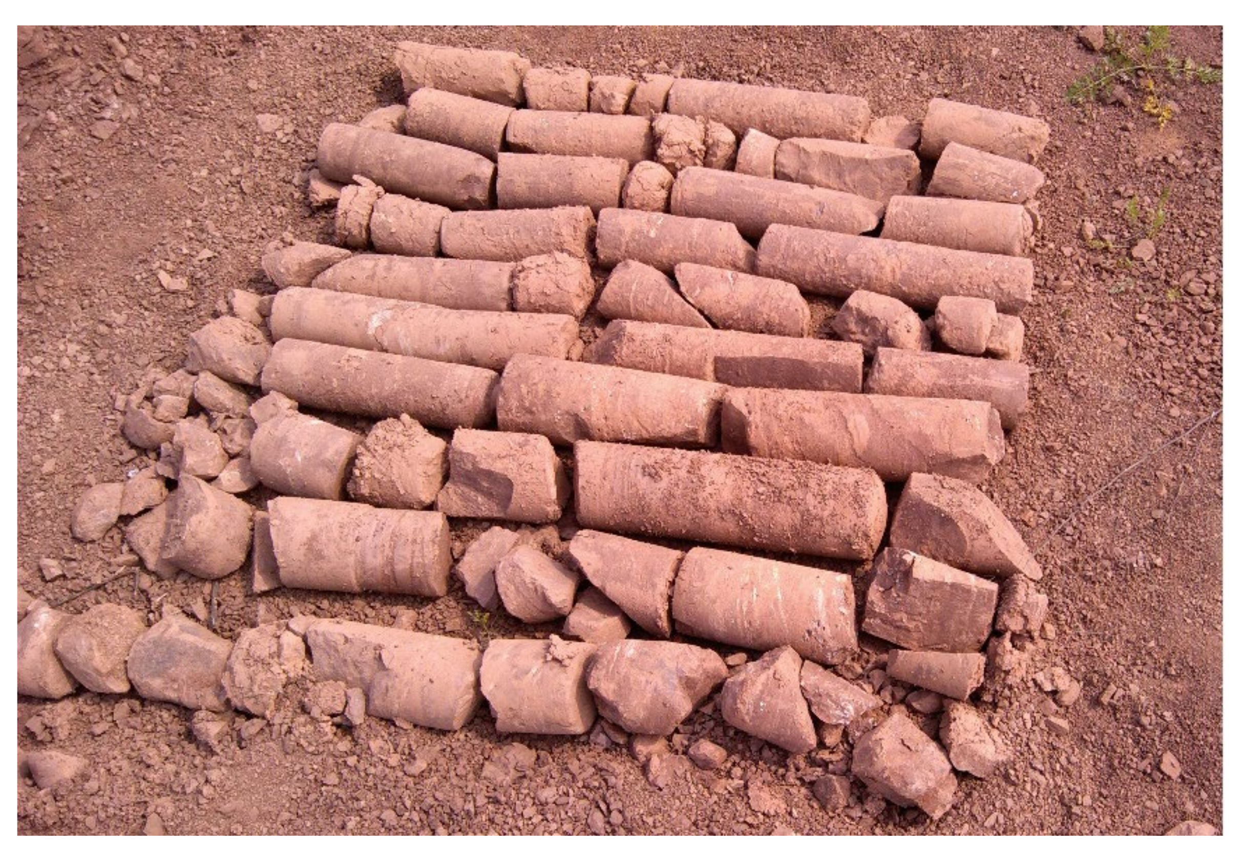
2.1. Geological Setting and Sample Description

The site of the in-situ test is near Yumu Mountain in Hunan Province, located in the southwest of Hengyang city (26°48′11″ N; 112°43′11″ E), which is the part of Hengyang Basin in Chiang-nan Hilly Region that red beds are mostly distributed. Due to the weak lithology of red beds, strongly weathering process has occurred, with more than 1200 km2 of red soil and non-zonal purple soil widely having developed in Hengyang Basin, of which calcareous purple soil accounts for 72%.
Samples were obtained from a test pit, as shown in Figure 1. It was reddish brown and argillaceous, and in the shape of broken blocks or short columns. In addition, joints and fissures were well developed, and softening and collapse would occur in contact with water. According to the rock slice identification, it consists of approximately 40–50% silt and more than 50% clay, and the minerals are mainly quartz. The results of geological survey are shown in Table 1. This sample is strongly weathered silty mudstone, which belongs to the category of soft rock.

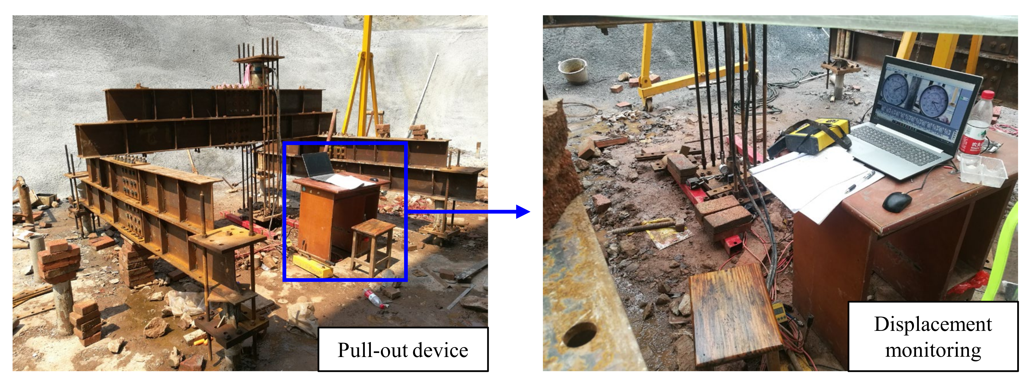
2.2. Test Scheme and Preparation

In this study, pure cement slurry steel pipe micro-pile with a diameter of 170 mm was used. The grouting materials were PC 42.5R cement (compressive strength equals to 42.5 MPa) and water, and the water cement ratio was 0.5. The material for pipe was Q235 steel (yield strength equals to 235 MPa), the outer diameter of pipe was 89 mm, and the wall thickness was 4 mm.
In order to analyze the influence of pile length on the pile uplift bearing capacity, three groups of different pile lengths were designed for comparison test, namely AP1~AP4 with pile length of 5 m, BP5~BP8 with pile length of 7 m, CP9~CP12 with pile length of 9 m. To measure the relative displacement of the pile and soil at different depths, a certain number of vibrating string strain gauges were welded and installed symmetrically along the depth direction in the test series AP1, AP3, BP5, BP7, CP9, and CP11, and the strain gauges were protected by wrapping gauze and applying epoxy resin on their surface. The measurement range of strain gauges was 3000 με with an accuracy of ±1 με. The layout of test scheme is shown in Figure 2.
Before the test, the bore holes were formed by water drilling with a geological drilling rig; at the same time, slurry-supported excavation was used to prevent the hole wall from collapsing, as shown in Figure 3a. The diameter of the borehole was 170 mm, and there were 12 boreholes in total. After drilling, the steel pipe pile was vertically lowered to the center of the borehole by the geological drilling rig, and the steel pipe pile was aligned on top of it by adding welding alignment brackets so that the steel pipe pile could be firmly installed, as shown in Figure 3b. After that, the grouting conduit was used to repeatedly inject grout from bottom to top, as shown in Figure 3c. After grouting, the piles were left to maintain for 28 days, as shown in Figure 3d. The compressive strength after 28 days of curing was measured as 32.4~38.6 MPa.

2.3. Testing Process

This paper only studied the micro-pile with constant cross-section. According to the Chinese Technical Code for Building Pile Foundations (JGJ94-2008) [36], the standard value of ultimate uplift bearing capacity of single pile can be calculated as Equation (1):
T u k = λ i q s i k u i l i
where Tuk is the standard value of ultimate uplift bearing capacity of single pile, kN; qsik is the standard value of ultimate compressive lateral resistance of layer i soil on the pile side surface, kN; ui is the pile circumference, m; li is the thickness of the i-th layer of soil around the pile, m; and λ is the pull-out resistance factor; according to the Standard for Geotechnical Investigation of Tall Building (JGJ/T 72-2017) [37] the value of pullout resistance factor for strongly weathered rock is 0.7, thus the value of the pullout coefficient was assumed as 0.7 in this study.
According to Equation (1) and the parameters provided in Table 1, the ultimate uplift bearing capacity of single pile with pile lengths of 5 m, 7 m, and 9 m was calculated as 224 kN, 314 kN, and 404 kN, respectively. The anchor pile beam device and a hydraulic jack (Figure 4 were adopted to achieve graded loading and unloading by the slow maintenance load method, according to the Chinese Technical Code for Testing of Building Foundation Piles (JGJ106-2014) [38]. The bottom center of the jack coincides with the center of the test pile cross-section, and the digital display pressure gauge on the hydraulic cylinder can directly display the loaded value of loads. The piles were loaded until they were damaged or could not be further loaded, and the graded loading amount was taken as 0.1 times of the ultimate bearing capacity of the uplift resistance, namely 20 kN, 30 kN, and 40 kN for micro-piles with length of 5 m, 7 m, and 9 m, respectively. The deformation of the test pile was measured by two dial indicators with a range of 50 mm, and an accuracy of 0.01 mm. All the dial indicators were fixed to the reference beam with magnetic meter holders arranged symmetrically at the pile head.

2.4. Testing Results Presentation

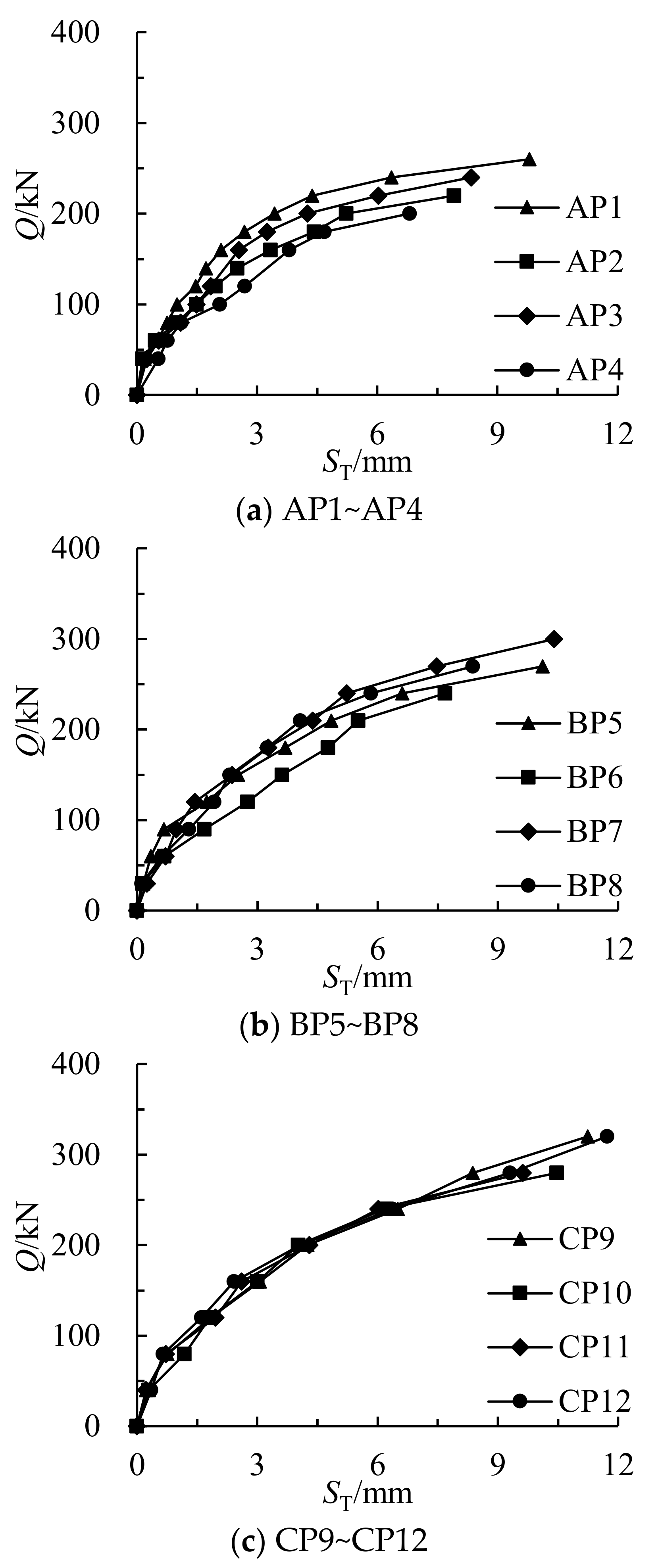
2.4.1. Vertical Uplift Bearing Capacity and Uplift Displacement

The variation of uplift load (Q) with uplift displacement (ST), namely the uplift static load curves (Q-ST), of each test series are shown in Figure 5. According to the Chinese Technical Code for Testing of Building Foundation Piles (JGJ 106-2014) [37], if the Q-ST curve is steeply falling type, the load value corresponding to the starting point of its obvious steep fall should be taken as the ultimate bearing capacity of micro-pile, and when the Q-ST curve is slowly changing type, the maximum loading value should be taken as the ultimate bearing capacity. Accordingly, the ultimate bearing capacity of the single pile and the corresponding ultimate displacement are shown in Table 2.
Figure 5 indicates that the uplift displacement increased non-linearly with the increase in uplift load, showing a trend of slow increase at the beginning and steep increase at the end. This phenomenon may be caused by the change in the friction state between the pile and the soil. In the early stage, the pile body and soil were in the stage of static friction when the uplift load is small. With the gradual increase in load, the pile body and soil were in the stage of transition from static friction to sliding friction. When it completely entered the stage of sliding friction, the monitored displacement increases steeply with the increase in load.
Seen from Table 2, it can be found that the uplift displacement of pile top and the ultimate bearing capacity of single pile against uplift both increase nonlinearly with the increase in pile length. It indicated that in strongly weathered silty mudstone foundation, the uplift bearing capacity can be improved by increasing the length of micro-pile.

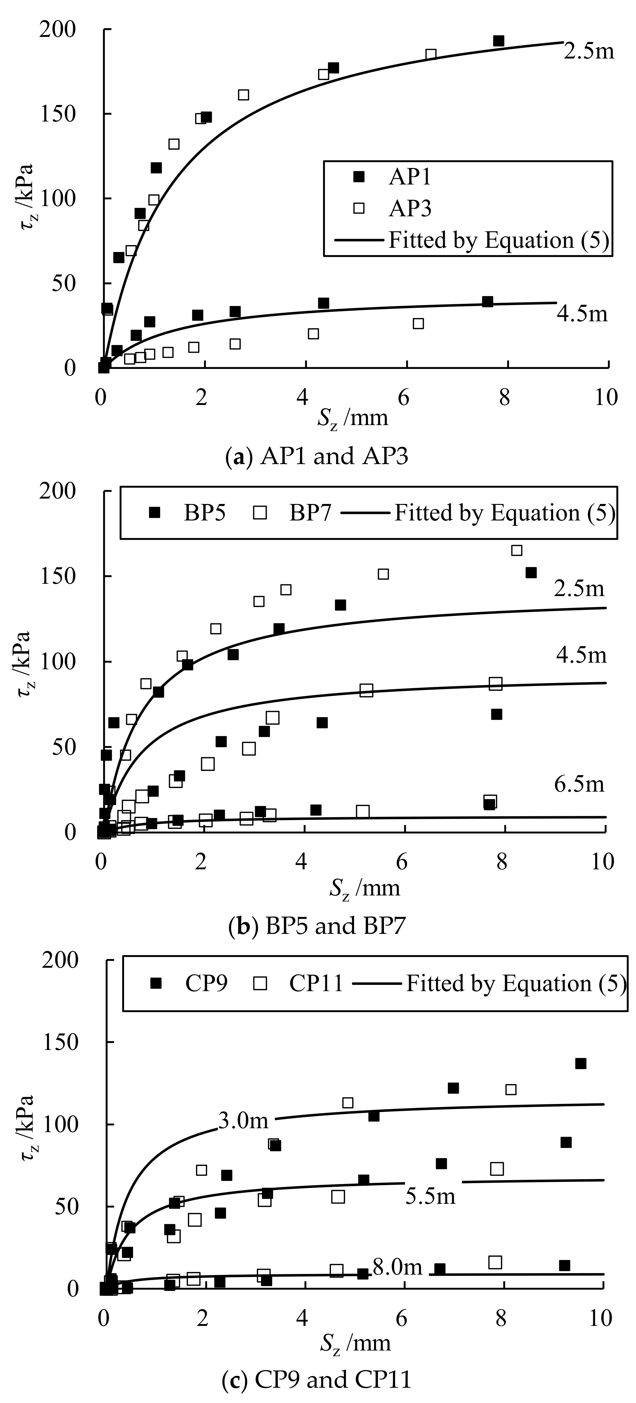
2.4.2. Lateral Friction and Relative Displacement between Soil and Pile

When the micro-pile was subjected to uplift load, both the micro-pile and the surrounding rock or soil would produce displacement changes, and the magnitude of the lateral friction resistance was determined by the relative displacement of the pile-soil. Thus, the uplift bearing capacity of micro-pile was determined by the lateral friction resistance. The load transfer function of pile lateral friction resistance, namely the variation of lateral friction resistance with relative displacement at pile-soil interface, can truly reflect the pile-soil interaction mechanism, so the correct selection of load transfer function and determination of its parameters are the key to analyze the uplift behavior of micro-pile. The axial force of each section of the test pile can be calculated according to Equation (2):
Q zi = E ε zi A
where Qzi is the axial force of the section at position z under the i-th load, kN; E is the elastic modulus of pile, kPa; ε is the strain of the section at position z under the i-th load, 10−6; and A is the cross-sectional area of the pile body, m2.
The lateral friction resistance of pile can be calculated according to Equation (3):
τ z i = Q z i Q z + 1 , i π D l z
where τzi is the lateral friction resistance of the pile between the section z and section z + 1 under the i-th load, kPa; Qzi, Qz+1,i is, respectively, the axial force of the pile at the section z and section z + 1 under the i-th load, kN; D is the pile diameter, m; and lz is the pile length between the section z and section z + 1, m.
The relative displacement of the soil and pile can be calculated according to Equation (4):
S z i = S t i j = 1 z l j 2 ( ε j + ε j + 1 )
where Szi is the relative displacement of the soil and pile between the section z and section z + 1 under the i-th load, mm; Sti is the measured displacement at the top of the pile under the i-th load, mm; lj is the pile length of the j-th section, mm; and εj, εj+1 is the strain of pile in section j, section j + 1, respectively.
Accordingly, the pile lateral friction resistance of different test piles and their corresponding pile-soil relative displacement were calculated from Equations (2)–(4) based on the results of field test. The variations of pile lateral friction resistance with pile-soil relative displacement of each test pile are shown in Figure 6.
Figure 6 shows that the pile lateral frictional resistance at different depths of each test pile exhibited a trend of rapid increase at the beginning and then gradually slowed down with the increase in pile-soil relative displacement. The variation curves of pile-side friction resistance versus pile-soil relative displacement for micro-piles with different pile lengths are all hardened or strengthened, which is similar to the results in the literature [39,40]. The closer to the ground surface and the smaller the pile length, the more significant the variation of pile lateral friction resistance with pile-soil relative displacement. In addition, when the depth and the relative displacement of pile-soil are certain, the pile lateral friction resistance of each test pile differs. This indicates that the lateral friction resistance between pile and soil is changing, namely the shear stiffness of the pile-soil contact surface varies for different pile lengths.
Considering that the relative pile-soil displacement and the pile lateral friction resistance were non-linear, the variation between them actually reflects the variation of the pile-soil contact shear stiffness. Meanwhile, the pile length also influences the development, transmission and distribution of the pile lateral friction resistance. On that basis, the equation for predicting the pile lateral friction resistance of micro-piles considering the influence of pile length was proposed as Equation (5):
τ z = ( λ 1 λ 2 λ 3 z H ) S z 1 / k + S z / τ max
where λ1 is the shape adjustment coefficient; λ2 is the slope fitting coefficient, which is approximately equal to the slope of variation curve of pile lateral friction resistance versus pile length; λ3 is the peak coefficient, which is the ratio of the corresponding length of the maximum lateral friction resistance to the full length of the pile; k is the initial shear stiffness of the rock or soil, MN/m3; and τmax is the ultimate lateral friction resistance of the pile, kPa.
The pile-soil relative displacement and the corresponding pile-side friction resistance at depths of 2.5, 3.0, 4.5, 5.5, and 6.5 m in Figure 6 were fitted by this equation, and the fitted curves of pile lateral friction resistance with pile-soil relative displacement were obtained, as shown in Figure 6. The correlation fitting parameters and correlation coefficients are shown in Table 3.
Seen from the fitting curves in Figure 6, it was observed that the tested values deviated from the fitting curve when the relative pile-soil displacement increased from 0 to 2 mm, while they became closer to the predicted values as the relative pile-soil displacement gradually increase. This phenomenon might be caused by the change of friction type at the pile-soil interface. During the in-situ test, when the relative pile-soil displacement was small, a certain elastic deformation would firstly occur at the cemented area formed by the pile and the surrounding solidified cement slurry under the pullout force, and the force acted in the tangent direction of pile-soil interface was mainly generated by the bond strength of the soil, which was the static friction. As the relative pile-soil displacement continued to increase, a plastic deformation or even a gradual destruction would produce at the bond area of the pile-soil interface, the pile lateral friction resistance will be gradually transformed from static friction to sliding friction. The sliding friction depends on the normal stress and friction coefficient acting on the pile-soil interface. Therefore, the variation curve of pile lateral friction resistance with the relative pile-soil displacement would gradually become stable, while certain fluctuations would occur when the relative pile-soil displacement was relatively small.
Table 3 shows that all the fitted parameters are correlated with the pile length with correlation coefficients greater than 0.81, indicating that Equation (5) can be used to predict the pile lateral friction resistance under different pile lengths, depths, and relative pile-soil displacements, and to characterize the variable shear stiffness properties of the pile-soil contact surface.

3. Numerical Simulation and Parameter Inversion

In order to better simulate the variation of pile-soil contact stiffness with pile-soil displacement, this section implemented the simulation of pile-soil contact variable shear stiffness by Midas GTS NX software based on the relationship between the measured pile-soil relative displacement and lateral friction resistance. On this basis, the relevant material parameters of the red-bedded soft rock were inverted by numerical simulation.

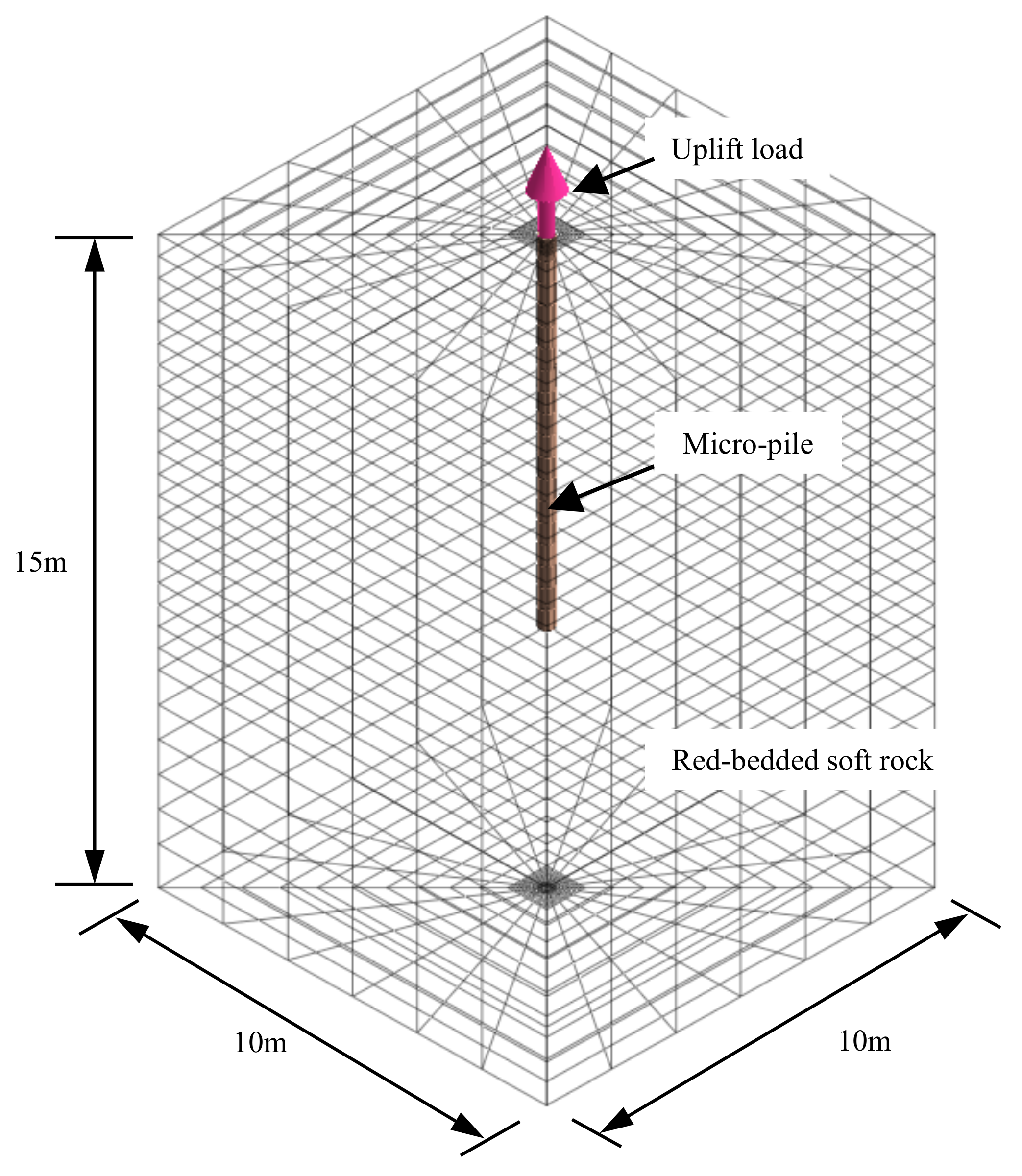
3.1. Numerical Model

Midas GTS NX numerical calculation software was used to invert the parameters related to the mini-pile pullout test, and a 3D solid model was used for modeling with dimensions of 10 m × 10 m × 15 m (length × width × depth), as shown in Figure 7. The hexahedral solid mesh was used for division, and the meshes near the pile-soil interface were further encrypted, with a total of 13,646 elements and 42,963 nodes. The Mohr–Coulomb elasto-plastic constitutive model was used for the rock body, and the linear elastic constitutive model was used for the micro-pile. The boundary condition of this numerical model was set up with no deformation constraints in lateral direction. In order to simulate the field micro-pile uplift static load test, the uplift load was also applied on the top of the pile, and the load level was consistent with the field test.
To better simulate the change of pile-soil contact stiffness with pile-soil displacement, grid elements were set up for the pile-soil interface contact at the junction position of the cement injection body of the micro-pile and the rock body, and the editing function of the software was used to realize the embedding of Equation (5) for the description of pile-soil contact variable shear stiffness Kt. During the numerical simulation, the variation curves of pile lateral friction resistance versus pile-soil relative displacement are shown in Figure 8, where the negative value indicates that the direction of pile lateral friction resistance and displacement is the same as the direction of gravity. In addition, it was shown that the pile-soil normal stiffness Kn is about 150–200 times of the elastic modulus of the geotechnical body [34]. Since the loading direction of this micro-pile was vertical, the normal load at the contact surface was basically constant, and it was observed in pre-study that the normal stiffness had almost no effect on the calculation results by changing the normal stiffness Kn. Therefore, in order to simplify the calculation, 200 times of the elastic modulus of the geotechnical body was taken as the normal stiffness Kn of the pile-soil contact, which was used for the subsequent numerical simulation analysis.

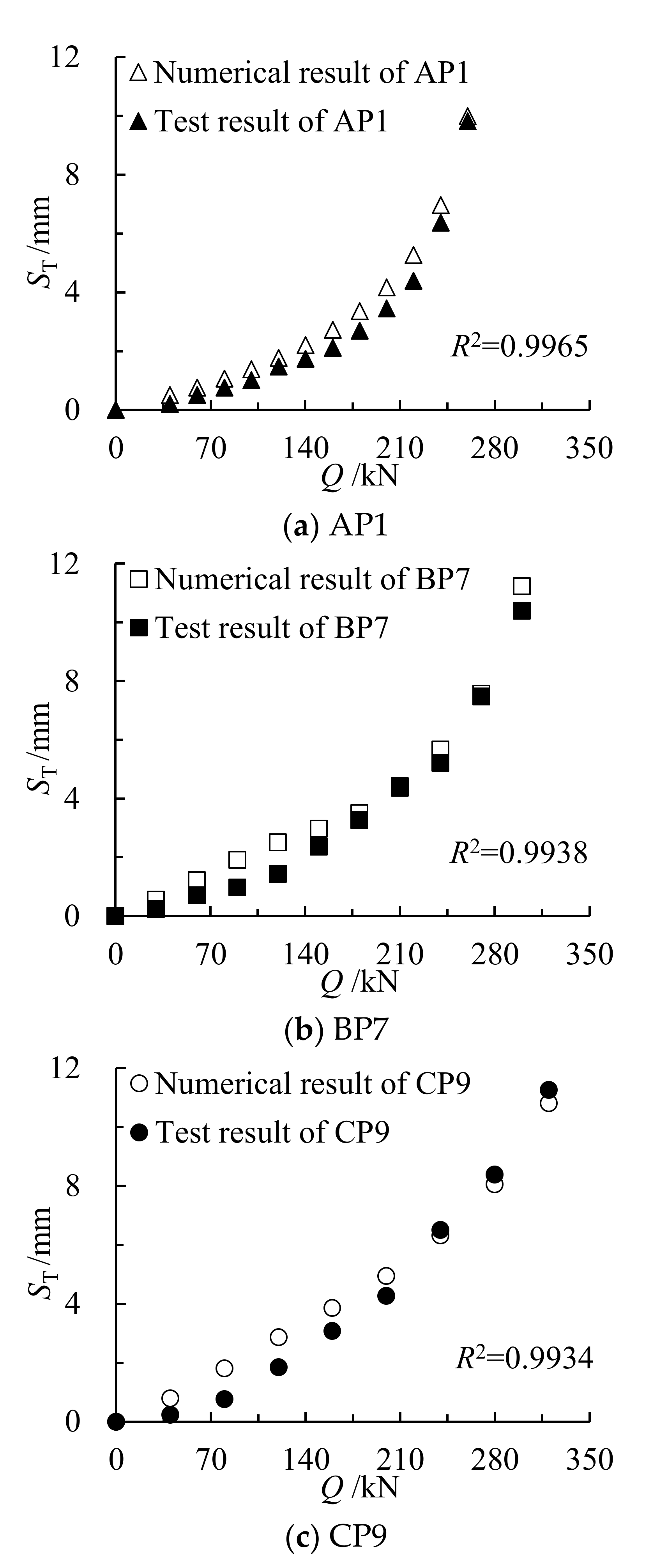
3.2. Numerical Results

Based on the field test results of AP1, BP7, and CP9 test piles, the minimum distance between the measured and simulated values of uplift displacement under the same level of load was taken as the target function. Through several trial calculations, when the target function was smallest, the geotechnical calculation parameters (elastic modulus E, Poisson’s ratio v, cohesion force c, and internal friction angle φ) were selected as the calculation parameters for subsequent modeling. The measured Q-ST curves and calculated Q-ST curves are shown in Figure 9.
Figure 9 shows a good correlation between the numerical simulation results of each test pile and the measured results, the correlation coefficients were all greater than 0.99. The calculated target function value of AP1, BP5, and CP9 test piles was 1.95, 0.47, and 0.56 mm in order, with standard deviations of 1.21, 0.35, and 0.34, indicating that the material parameters finally selected in the inversion process were reasonable. Accordingly, the material parameters of red-bedded soft rock and micro-pile were obtained, as shown in Table 4.
The geotechnical body in this study is a strongly weathered silty mudstone, which has the characteristics of both mudstone and sandstone, and the elastic modulus and shear strength parameters obtained by inversion in Table 4 are between mudstone and sandstone, which is close to the results of the literature [23], indicating that the rock material parameters obtained by inversion are reasonable and can be used in the subsequent numerical simulation for investigating the effect of micro-pile against uplift.

4. Investigation on the Effect of Micro-Piles against Uplift

To analyze the effect of stress redistribution on soil deformation caused by slope excavation, and to further investigate the anti-uplift effect of micro-piles in red-bedded soft rock, a numerical model of anti-uplift of micro-piles in slope excavation was developed based on the aforementioned numerical simulation method and material parameters obtained by inversion. The treatment effect of single pile and group piles on subgrade uplift deformation caused by slope excavation was analyzed. Finally, the anti-uplift design method of micro-pile in red-bedded soft rock was proposed.

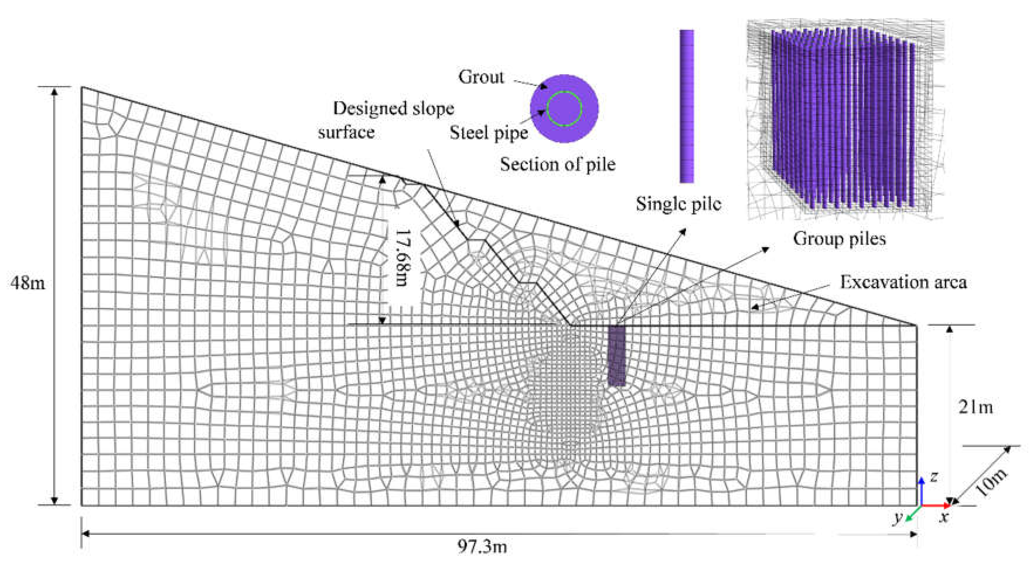
4.1. Numerical Model

According to the condition of field test, the slope height is 17.68 m, and the slope was designed to be divided into four grades, with the heights from top to bottom being 1.18 m, 6.5 m, 5 m, and 5 m, respectively. The side slope of each grade was 1(V):0.8(H), as shown in Figure 10.
The hexahedral solid mesh was used to divide, and the mesh around the pile-soil body was encrypted, with a total of 77,241 elements and 72,568 nodes after division. The left, right and bottom boundaries of the model were set as non-deformed boundaries, and the material parameters are shown in Table 4. The rest of the settings were the same as above.
Since the subgrade uplift was not only generated at a single point, but also unevenly occurred in a certain area, and the form of group piles was generally used for treatment in engineering practice, to investigate the effect of micro-piles on the uplift deformation of red-bedded soft rock subgrade, three working conditions were considered in the numerical simulation, namely no micro-piles, single pile, and group piles. In the single pile condition, three pile lengths of 5 m, 7 m, and 9 m were considered, and the pile was set up at the position that the maximum uplift deformation occurred under the condition of no piles. In the group piles condition, a square area (7 m × 7 m) was selected for numerical simulation, the shape center of the square area was the position that the maximum uplift deformation occurred under the condition of no piles, and a rectangular array of piles with a pile length of 7 m and a pile spacing of 1D~6D was used.

4.2. Effect of Single Micro-Pile against Uplift

According to the established numerical calculation model, the deformation field of red-bedded soft rock slope without micro-piles was obtained, as shown in Figure 11.
Figure 11 shows that the subgrade deformation was radially distributed, with the maximum uplift deformation as the center of the circle and gradually decreasing at the distal end. The maximum uplift deformation appeared at the bottom of the designed slope surface after excavation, which was 5.12 mm. This value has exceeded the requirement of 4 mm of allowable deformation of ballastless track of Chinese high-speed railway. The numerical results of the red-bedded soft rock subgrade after setting a micro-pile with 7 m pile length is shown in Figure 11b.
Figure 11b shows that the distribution of the deformation field of the slope after the installation of micro-piles was similar to that without the installation, which was also radially distributed with the maximum uplift deformation as the center. At this time, the maximum uplift deformation was 3.69 mm, which could meet the requirement of less than 4 mm. The micro-piles were influenced by the uplift deformation that generated by the surrounding rock mass, which was passively subjected to an upward tensile force, as shown in Figure 12a. In order to maintain its own equilibrium, the sidewall around the pile was subjected to positive friction (opposite to the direction of gravity) from the surrounding rock mass in the upper buried area, while it was also affected by negative friction (same as the direction of gravity) in the lower buried area, as shown in Figure 12b.
Observed from Figure 12, the distribution of pile axial force along the length of the pile was parabolic: the axial force firstly increased then decreased with the increase in depth, the maximum axial force appeared at the middle of the pile. In addition, both positive and negative pile lateral friction resistance existed along the pile, and the pile lateral friction resistance was zero at the position of about half of the pile length. The calculated results of the subgrade uplift deformation after installation of micro-pile with different length are shown in Table 5.
Table 5 indicates that the micro-piles can effectively reduce the uplift deformation of the subgrade, and the longer the pile length was, the more obvious this inhibiting effect was. However, the uplift deformation nonlinearly decreased with the increase in pile length, it decreased by 0.89 mm and 0.51 mm when the pile length increased from 5 m to 7 m, and 7 m to 9 m, respectively. It is not necessary to pursue the reduction in the uplift displacement only by increasing the pile length in the design of micro-piles in red-bedded soft rock.
In addition, during the process of subgrade uplift due to slope excavation, the axial force and lateral friction resistance of the pile caused by rock and soil were relatively small. The maximum axial force on the pile body was only 11~30 kN, and the maximum lateral friction resistance was only 10~17 kPa, which were much lower than the uplift bearing capacity of the micro-pile itself. It demonstrated that the uplift bearing capacity of the micro-pile in red-bedded soft rock was not fully developed. As mentioned above, the magnitude of lateral friction resistance of micro-pile is closely related to the magnitude of pile-soil relative displacement, the allowable deformation of subgrade is only 4.0 mm, hence the lateral friction resistance along the pile should be correspondingly small.
It can be concluded that the control of pile-soil relative displacement is important for the treatment of subgrade uplift deformation with micro-piles, and the pile-soil relative displacement is determined by the pile-soil contact shear stiffness. Therefore, the tensile strength of pile can be appropriately reduced when designing the pile material, while improving the quality of grouting in the construction of pile to increase the pile–soil contact shear stiffness, so as to reduce the uplift deformation of red-bedded soft rock subgrade.

4.3. Effect of Group Micro-Piles against Uplift

The numerical simulation results of the maximum uplift displacement of red-bedded soft rock slope treated by group piles in a 7 m × 7 m square area with different pile spacing are shown in Figure 13.
Figure 13 shows that the maximum uplift deformation increased with the increase of pile spacing, and it gradually became stable when the pile spacing was greater than 4D. By the time the pile spacing increased to 3D, the maximum value of the uplift deformation of the treated subgrade was 3.98 mm, which was very close to the allowable value of 4.00 mm. In addition, compared to the results of the single pile condition with the pile length of 7 m, the position that the maximum uplift displacement appeared was changed, as shown in Figure 14.
Observed from Figure 14, the maximum uplift deformation occurred at the edge of the square area when the pile spacing was 1D and 2D, while it appeared at the middle of two neighboring piles when the pile spacing was 3D~6D. The use of reasonable pile spacing can make the original maximum deformation position offset to the boundary between the reinforced and unreinforced area. It also demonstrated that the two adjacent piles are mutually influenced when the pile spacing is in the range of 2D~3D. It is suggested to select a relatively small pile spacing to set the group piles. Furthermore, the micro-piles should be placed beyond a certain range of the area to be reinforced. It is recommended that each side can exceed the 3D range of the area to be reinforced for pile reinforcement.
General speaking, for the site selected in this study, in order to make the maximum uplift deformation of the red-bedded soft rock subgrade less than 4 mm, a single pile with 170 mm pile diameter and 7 m length can be selected to treat the small and partial area of uplift, or a group of piles with 170 mm pile diameter and 7 m pile length arranged in a rectangular array with a pile spacing of 3D can be treated for the large area of potential uplift.

5. Design Method of Micro-Piles in Red-Bedded Soft Rock against Uplift

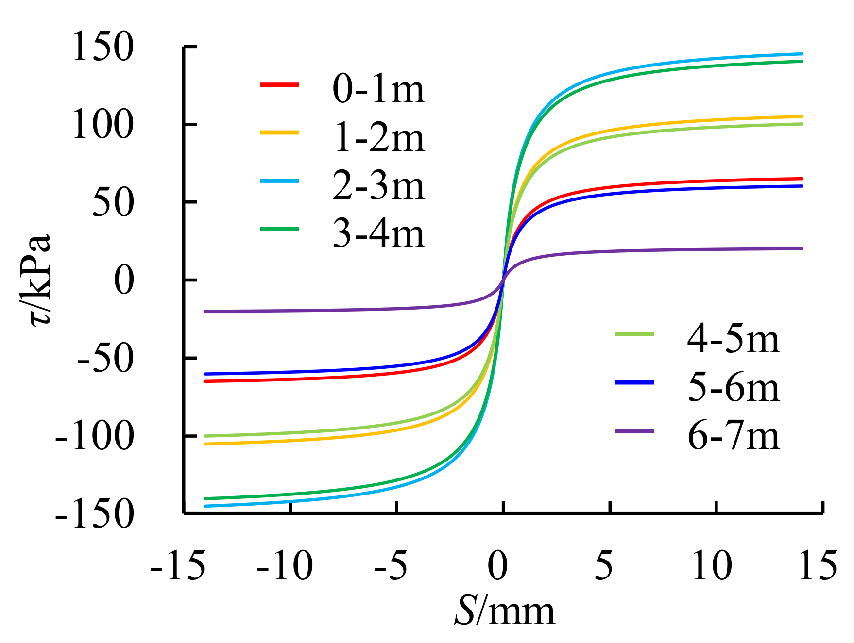
5.1. Neutral Point of Micro-Pile

The pile section size is the most fundamental parameter for pile design, which is generally determined by the maximum axial force applied to the pile and the location of the action point. After the excavation of the road graben slope, the uplift of the subgrade occurred due to the unloading and rebound effect of the geotechnical body. In this process, part of the pile body was subject to the uplift effect of the surrounding geotechnical body, resulting in the upward movement of the pile body. When the upward displacement of the pile body was less than the uplift deformation of the geotechnical body, the micro-pile would move downward relatively to the soil body, and the pile body was subject to the upward positive friction resistance; when the upward displacement of the pile body was greater than the uplift deformation of the geotechnical body, the micro-pile would move upward relatively to the soil body, and the pile body was subject to the downward negative friction resistance. The point that the friction resistance became zero was referred to the neutral point, where the axial force was the maximum.
According to the stress field of micro-pile with different pile lengths, the neutral point depths of 5 m, 7 m and 9 m pile lengths were 2.55 m, 3.29 m, and 4.32 m, respectively, thus the depth of neutral point of the micro pile in red-bedded soft rock at this site was 0.47–0.51 times of pile length. It can be seen that the location of the neutral point of micro pile in red bed soft rock subgrade was approximately the middle of the pile body, and the neutral point moved slightly upward with the increase of pile length. Some measures could be taken below the neutral point to increase the anti-uplift effect of micro-pile, such as increasing the bond strength between the pile body and soil, or increasing the cross-sectional area of the pile body, so as to increase the lateral shear stiffness of the pile soil below the neutral point.
Compared to the recommended depth of neutral point in specification, the calculated neutral point was quite different. It should be attributed to the difference between the effect of unloading rebound after the slope excavation and the effect of soil consolidated settlement on the piles. Conventional piles moved downward under the external load, the pile displacement was less than the settlement displacement of the soil due to consolidation, the pile moved upward relatively to the soil, and the soil applied the downward negative friction resistance to the pile body in a certain pile length range. While, after the excavation of the slope, the rock and soil body around the pile uplift upward and caused upward tension in the pile body. Therefore, the depth of the neutral point of the micro-pile in red-bedded soft rock cannot be taken with reference to the specifications.
Furthermore, in the uplift process of subgrade, the depth of neutral point of micro-pile is related to the amount of uplift deformation of soil around the pile, the boundary condition of pile, and the lateral stiffness of soil around the pile, so the depth of neutral point is a variable, which changes with external conditions. At present, there are not many relevant research results and less experience accumulated associated with the determination of the neutral point depth under the condition of subgrade uplift. In order to guarantee the anti-uplift effect of the micro-pile, it can be considered in a conservative way and the neutral point position can be taken as a small value.

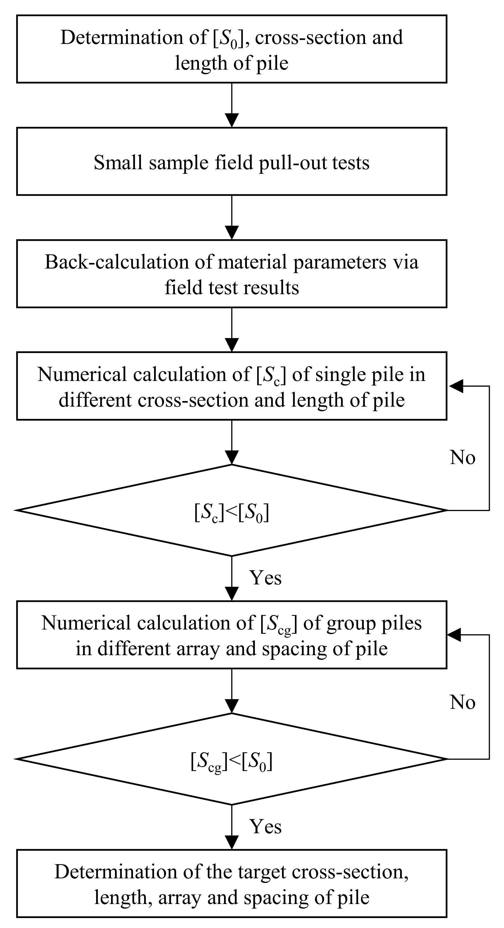
5.2. Anti-Uplift Design Method of Micro-Piles in Red-Bedded Soft Rock

Through the in-situ test and numerical simulation analysis, it was found that the micro-pile can be used for the treatment of uplift deformation of red-bedded soft rock subgrade. In the design, the pile diameter, pile length, and pile spacing are the key parameters. With the goal of engineering economy, it is recommended that the design of micro-pile should be carried out according to the following process. The flowchart is shown in Figure 15.
  • Determine the allowable uplift displacement of subgrade [S0] based on working condition, and pre-set the micro-pile cross-section and length.
  • Conduct the small sample field pull-out tests on micro-piles in the area to be treated to obtain site-related test data.
  • Conduct numerical simulations to invert the relevant material parameters based on the field test results.
  • Set up the numerical model of micro single-pile in red-bedded soft rock subgrade after excavation, perform trial calculations by changing the pile cross-section as well as the length, and calculate the corresponding subgrade uplift displacement [Sc] until [Sc] < [S0], to obtain the target pile cross-section and pile length.
  • According to the target pile cross-section and length, perform trial calculations by changing the array of piles as well as the pile spacing, and calculate the corresponding subgrade uplift displacement [Scg] until [Scg] < [S0], to obtain the target pile array and pile spacing.
Figure 15. Flow chart of anti-uplift micro-pile design.
Sustainability 14 11923 g015

6. Conclusions

An in-situ static load test was conducted on grouting steel pipe micro-piles in red-bedded soft rock foundation for the investigation of uplift behavior, and a numerical simulation was carried out for the analysis of the treatment effect of micro-piles on uplift deformation. Based on in-situ test and numerical simulation, the following conclusions could be drawn:
The uplift bearing capacity of micro-pile in red-bedded soft rock increased nonlinearly with the increase in pile length, and the variation curve of pile lateral friction resistance with pile-soil relative displacement showed a hardened type. The pile lateral friction resistance varied, and influenced by the pile length, on that basis, the load transfer function of pile lateral friction resistance, considering the influence of pile length, was proposed. The predicted pile lateral friction resistance shows a good correlation with the measured result; all the correlation coefficients were greater than 0.81.
The uplift deformation of subgrade without piles was radially distributed with the maximum value as the center, and the maximum uplift deformation appeared at the bottom of the designed slope surface after excavation as 5.12 mm. By setting micro-piles at the position that the maximum uplift deformation occurred, the deformation caused by the excavation could be effectively reduced.
A single micro-pile with a length of 7 m could decrease the maximum uplift deformation to 3.69 mm. The distribution of axial force along the pile was parabolic with the maximum axial force appeared at the middle of the pile. In addition, both positive and negative pile lateral friction resistance existed along the pile, and the pile lateral friction resistance was zero at the position of about half of the pile length.
When a rectangular array of group piles with a length of 7 m was set up, the maximum uplift deformation of the subgrade increased with the increase in pile spacing, and it gradually became stable when the pile spacing was greater than 4D. When the pile spacing increased to 3D, the maximum value of the uplift deformation of the subgrade was 3.98 mm, which was very close to the allowable value of 4.00 mm. The position that the maximum uplift displacement appeared changed compared to the results of the no pile and single pile condition.

Author Contributions

Conceptualization, R.Z., H.L. and R.N.; Methodology, H.L. and Z.L.; Software, H.L.; Validation, H.L., R.Z. and Z.L.; Formal Analysis, H.L.; Data Curation, Z.L.; Writing—Original Draft Preparation, H.L. and R.N.; Writing—Review and Editing, H.L. and Z.L.; Supervision, R.Z.; Funding Acquisition, R.Z. All authors have read and agreed to the published version of the manuscript.

Funding

This research was funded by the National Natural Science Foundations of China grant number 51978085, Research and Development Project of China National Railway Group Co., Ltd. grant number K2020G036 and K2019G045.

Institutional Review Board Statement

Not applicable.

Informed Consent Statement

Not applicable.

Data Availability Statement

All data included in this manuscript are available upon request by contact with the corresponding author.

Conflicts of Interest

The authors declare no conflict of interest.

References

  1. Zhang, Z.; Gao, W. Effect of different test methods on the disintegration behaviour of soft rock and the evolution model of disintegration breakage under cyclic wetting and drying. Eng. Geol. 2020, 279, 105888. [Google Scholar] [CrossRef]
  2. Zhou, M.; Li, J.; Luo, Z.; Sun, J.; Xu, F.; Jiang, Q.; Deng, H. Impact of water-rock interaction on the pore structures of red-bed soft rock. Sci. Rep. 2021, 11, 73–98. [Google Scholar] [CrossRef] [PubMed]
  3. Huang, K.; Kang, B.; Zha, F.; Li, Y.; Zhang, Q.; Chu, C. Disintegration characteristics and mechanism of red-bed argillaceous siltstone under drying-wetting cycle. Environ. Earth Sci. 2022, 81, 336. [Google Scholar] [CrossRef]
  4. Liu, Z.; He, X.; Zhou, C. Influence mechanism of different flow patterns on the softening of red-bed soft rock. J. Mar. Sci. Eng. 2019, 7, 155. [Google Scholar] [CrossRef]
  5. Zhou, Z.; Chen, S.; Wang, Y.; Dai, Z. Crack evolution characteristics and cracking mechanism of red beds in central Sichuan during seepage and swelling. Geofluids 2021, 2021, 9981046. [Google Scholar] [CrossRef]
  6. Huang, W.; Feng, R.; Fu, H.; Chen, J.; Feng, Z. Mechanical properties of soft rocks subjected to water-rock reaction and cyclic pressure. Adv. Civ. Eng. 2022, 2022, 1533464. [Google Scholar] [CrossRef]
  7. Yang, Y.C.; Zhou, J.W.; Xu, F.G.; Xing, H.-G. An experimental study on the water-induced strength reduction in Zigong argillaceous siltstone with different degree of weathering. Adv. Mater. Sci. Eng. 2016, 2016, 4956986. [Google Scholar] [CrossRef]
  8. Mana, D.; Gourvenec, S.; Randolph, M.F. Numerical modelling of seepage beneath skirted foundations subjected to vertical uplift. Comput. Geotech. 2014, 55, 150–157. [Google Scholar] [CrossRef]
  9. Kim, N.; Park, D.; Jung, H.; Kim, M.I. Deformation characteristics of tunnel bottom after construction under geological conditions of long-term deformation. Geomech. Eng. 2020, 21, 171–178. [Google Scholar] [CrossRef]
  10. Tao, X.; Su, Y.; Zhu, Q.; Wang, W.-L. Pasternak model-based tunnel segment uplift model of subway shield tunnel during construction. Adv. Civ. Eng. 2021, 2021, 8587602. [Google Scholar] [CrossRef]
  11. Zhong, Z.; Li, A.; Deng, R.; Wu, P.P.; Xu, J. Experimental study on the time-dependent swelling characteristics of red-bed mudstone in Central Sichuan. Chin. J. Rock Mech. Eng. 2019, 38, 76–86. (In Chinese) [Google Scholar]
  12. Dai, Z.; Guo, J.; Zhou, Z.; Chen, S.X.; Li, J.; Yu, F. Inversion and prediction of long-term uplift deformation of high-speed railway subgrade in Central Sichuan red-bed. Chin. J. Rock Mech. Eng. 2020, 39, 3538–3548. (In Chinese) [Google Scholar]
  13. Veludo, J.; Julio EN, B.S.; Dias-da-Costa, D. Compressive strength of micropile-to-grout connections. Constr. Build. Mater. 2012, 26, 172–179. [Google Scholar] [CrossRef]
  14. Malik, B.A.; Shah, M.Y.; Sawant, V.A. Influence of micropile parameters on bearing capacity of footings. Environ. Sci. Pollut. Res. 2021, 28, 48274–48283. [Google Scholar] [CrossRef]
  15. Jeng, C.; Lin, C. Performance analysis of slopes reinforced using micropiles. J. Perform. Constr. Facil. 2018, 32, 04018008. [Google Scholar] [CrossRef]
  16. Seo, H.; Prezzi, M.; Salgado, R. Instrumented static load test on rock-socketed micropile. J. Geotech. Geoenviron. Eng. 2013, 139, 2037–2047. [Google Scholar] [CrossRef]
  17. Lee, T.; Chul, I.J.; Kim, C. A method for reinforcing the ground adjacent to the footing using micropiles. Mar. Georesour. Geotechnol. 2016, 34, 341–355. [Google Scholar] [CrossRef]
  18. Zeng, Z.; Ye, M.; Wang, W.; Liu, J.; Shen, S.; Qahtan, A.A.S. Analysis on mechanical characteristics of CRTSII slab ballastless track structures in rectification considering material brittleness. Constr. Build. Mater. 2022, 319, 126058. [Google Scholar] [CrossRef]
  19. Cai, X.; Zhang, Q.; Wang, Q.; Cui, X.; Dong, B. Effects of the subgrade differential arch on damage characteristics of CRTS III slab track and vehicle dynamic response. Constr. Build. Mater. 2022, 327, 126982. [Google Scholar] [CrossRef]
  20. Zhang, Q.; Wang, J.; Wang, W.; Bai, S.; Lin, P. Study on slope stability due to the influence of excavation of the high-speed rail tunnel. Geomat. Nat. Hazards Risk 2019, 10, 1193–1208. [Google Scholar] [CrossRef]
  21. Wang, G.; Chen, W.; Cao, L.; Li, Y.; Liu, S.; Yu, J.; Wang, B. Retaining technology for deep foundation pit excavation adjacent to high-speed railways based on deformation control. Front. Earth Sci. 2021, 9, 735315. [Google Scholar] [CrossRef]
  22. Duan, J.; Yang, G.; Hu, M.; Wang, G.; Lin, Y. Heave performance of a ballastless track subgrade of double line high-speed railway filled with micro-expansive andesite under water immersion. Constr. Build. Mater. 2020, 252, 119087. [Google Scholar] [CrossRef]
  23. Dai, Z.; Guo, J.; Yu, F.; Zhou, Z.; Li, J.; Chen, S. Long-term uplift of high-speed railway subgrade caused by swelling effect of red-bed mudstone: Case study in Southwest China. Bull. Eng. Geol. Environ. 2021, 80, 4855–4869. [Google Scholar] [CrossRef]
  24. Wang, P.; Ye, Y.; Zhang, Q.; Liu, J.; Yao, J. Investigation on the sulfate attack-induced heave of a ballastless track railway subgrade. Transp. Geotech. 2020, 23, 100316. [Google Scholar] [CrossRef]
  25. Yu, F.; Tong, K.; Dai, Z.; Feng, G.-S.; Zhou, Z.; Chen, S.-X. Macro and micro research on swelling characteristics and deformation mechanism of red-bed mudstone in Central Sichuan, China. Geofluids 2022, 2022, 6431590. [Google Scholar] [CrossRef]
  26. Shan, Y.; Xiao, W.; Xiang, K.; Wang, B.; Zhou, S. Semi-automatic construction of pile-supported subgrade adjacent to existing railway. Autom. Constr. 2022, 134, 104085. [Google Scholar] [CrossRef]
  27. Shan, Y.; Zhou, X.; Zhou, S. One-dimensional semi-analytical model on longitudinal thermal loads of a tram track pile-plank structure buried beneath the pavement. Arch. Civ. Mech. Eng. 2021, 21, 36. [Google Scholar] [CrossRef]
  28. Wei, L.; Li, S.; Lin, Y.; He, Q.; Zhang, C. Dynamic performance of a deep buried pile-plank structure transition section for a high-speed railway-field tests and numerical analyses. Transp. Geotech. 2020, 25, 100408. [Google Scholar] [CrossRef]
  29. Li, S.; Wei, L.; Chen, X.; He, Q. Numerical investigation on dynamic performance of a bridge-tunnel transition section with a deep buried pile-plank structure. Adv. Civ. Eng. 2020, 2020, 8885535. [Google Scholar] [CrossRef]
  30. Lee, T.; Im, J.; Kim, C.; Seo, M. An experimental study for reinforcing the ground underneath a footing using micropiles. Geotech. Test. J. 2018, 41, 648–663. [Google Scholar] [CrossRef]
  31. Kyung, D.; Lee, J. Uplift load-carrying capacity of single and group micropiles installed with inclined conditions. J. Geotech. Geoenviron. Eng. 2017, 143, 04017031. [Google Scholar] [CrossRef]
  32. Kyung, D.; Kim, G.-R.; Park, D.-S.; Kim, D.-H.; Lee, J.-H. Uplift behavior of group micropile according to embedded pile condition in sand. J. Korean Geotech. Soc. 2015, 31, 27–37. [Google Scholar] [CrossRef] [Green Version]
  33. Ying, C.; Hu, X.; Siddiqua, S.; Makeen, G.M.H.; Xia, P.; Xu, C.; Wang, Q. Model tests for observing the deformation characteristics of micropile boreholes during drilling in a soil-limestone mixture. Bull. Eng. Geol. Environ. 2021, 80, 6373–6393. [Google Scholar] [CrossRef]
  34. Gupta, R.K.; Chawla, S. Performance evaluation of micropiles as a ground improvement technique for existing railway tracks: Finite-element and genetic programming approach. Int. J. Geomech. 2022, 22, 04021287. [Google Scholar] [CrossRef]
  35. Zekavati, A.; Khodaverdian, A.; Jafari, M.; Hosseini, A. Investigating performance of micropiled raft in foundation of power transmission line towers in cohesive soil: Experimental and numerical study. Can. Geotech. J. 2018, 55, 312–328. [Google Scholar] [CrossRef]
  36. JGJ 94-2008; Technical Code for Building Pile Foundations. Ministry of Housing and Urban-Rural Development of the People’s Republic of China: Beijing, China, 2008.
  37. JGJ/T 72-2017; Standard for Geotechnical Investigation of Tall Buildings. Ministry of Housing and Urban-Rural Development of the People’s Republic of China: Beijing, China, 2017.
  38. JGJ 106-2014; Technical Code for Testing of Building Foundation Piles. Ministry of Housing and Urban-Rural Development of the People’s Republic of China: Beijing, China, 2014.
  39. Zhou, J.; Zhou, C.; Feng, Q.; Gao, T. Analytical model for load-transfer mechanism of rock-socketed drilled piles: Considering bond strength of the concrete-rock interface. Int. J. Geomech. 2020, 20, 04020059. [Google Scholar] [CrossRef]
  40. Xu, Y.; Kong, F.; Gao, K.; Hu, Z.; Han, L. The mechanism of mudstone skin friction of large-diameter and long piles based on the pile test of the Longhua Songhua River Bridge in Jilin Province, China. Arab. J. Geosci. 2021, 14, 2401. [Google Scholar] [CrossRef]
Figure 1. Photo of red-bedded soft rock core.
Sustainability 14 11923 g001
Figure 2. Layout of test scheme (mm).
Sustainability 14 11923 g002
Figure 3. Preparation process before in-situ test: (a) slurry-supported excavation, (b) placement of steel pipe pile, (c) grout injection, and (d) maintenance for 28 days.
Sustainability 14 11923 g003
Figure 4. The pull-out device and deformation monitoring.
Sustainability 14 11923 g004
Figure 5. Q-ST curves of test piles.
Sustainability 14 11923 g005
Figure 6. Variations of pile lateral friction resistance (τz) with pile-soil relative displacement (Sz) at different depth.
Sustainability 14 11923 g006
Figure 7. Numerical model for parameter inversion.
Sustainability 14 11923 g007
Figure 8. Variation curves of pile lateral friction resistance versus pile-soil relative displacement at different depth.
Sustainability 14 11923 g008
Figure 9. Q-ST curves of the measured and the calculated results.
Sustainability 14 11923 g009
Figure 10. Three-dimensional numerical model of slope excavation.
Sustainability 14 11923 g010
Figure 11. The deformation field of red-bedded soft rock slope.
Sustainability 14 11923 g011
Figure 12. Numerical results of axial force and lateral friction resistance along the 7 m single pile.
Sustainability 14 11923 g012
Figure 13. Maximum uplift displacement of subgrade treated by group piles with different spacing.
Sustainability 14 11923 g013
Figure 14. Comparison of the location that the maximum uplift displacement appeared.
Sustainability 14 11923 g014
Table 1. Index properties for strongly weathered silty mudstone.
Natural Unit WeightSaturated Uniaxial Compressive Strength Standard Value of End ResistanceStandard Value of Lateral FrictionCohesionInternal Friction AngleElastic ModulusPoisson’s Ratio
/(kN·m−3)/MPa/kPa/kPa/kPa/(°)/MPa
23.04.2~12.91500120903010000.25
Table 2. Test results of ultimate uplift bearing capacity and displacement.
Test SeriesUltimate Uplift Bearing Capacity/kNUltimate Uplift Displacement/mm
ValueAverage ValueValueAverage Value
AP12402156.356.11
AP22005.23
AP32206.03
AP42006.81
BP52402556.617.54
BP62407.69
BP72707.48
BP82708.38
CP932030011.2510.77
CP1028010.47
CP112809.62
CP1232011.74
Table 3. Fitting results of Equation (5).
Pile Length/mDepth/mFitting ParametersR2
λ1λ2λ3k/(MN·m−3)τmax/kPa
52.51.0002.000.50157.8221.80.9899
4.50.8132
72.51.0731.850.42210.5160.00.9638
4.50.9113
6.50.9231
93.01.1201.750.36266.7123.10.9114
5.50.9304
8.00.8078
Table 4. Material parameters obtained by inversion.
ItemNatural Unit WeightElastic ModulusPoisson’s RatioCohesionInternal Friction Angle
γ/(kN·m−3)E/GPavc/kPaφ/(°)
Steel pipe78.5208.00.25//
Slurry injection body24.08.00.20//
Red-bedded soft rock23.00.60.309030
Table 5. Calculated results of the subgrade uplift deformation after installation of micro-pile with different length.
Pile LengthUplift DeformationReduction in Uplift DeformationMaximum Soil-Pile Relative DisplacementMaximum Axial ForceMaximum Lateral Friction Resistance
/m/mm/mm/mm/kN/kPa
54.580.540.2511.259.54
73.691.430.4019.1617.29
93.181.940.3929.6617.00
Publisher’s Note: MDPI stays neutral with regard to jurisdictional claims in published maps and institutional affiliations.

