Article

Method for the Automated Inspection of the Surfaces of Photovoltaic Modules

1
Institute of Nuclear Energy and Industry, Sevastopol State University, 299053 Sevastopol, Russia
2
Department of Theoretical and Applied Mechanics, Russian University of Transport, 127994 Moscow, Russia
3
Laboratory of Power and Heat Supply, Federal Scientific Agroengineering Center VIM, 109428 Moscow, Russia
4
WWSIS “Horyzont”, 54-239 Wrocław, Poland
5
National Engineering School of Gabès, Processes, Energy, Environment and Electrical Systems, University of Gabès, LR18ES34, Gabes 6072, Tunisia
*
Authors to whom correspondence should be addressed.
Sustainability 2022, 14(19), 11930; https://doi.org/10.3390/su141911930
Submission received: 31 August 2022 / Revised: 19 September 2022 / Accepted: 19 September 2022 / Published: 21 September 2022
(This article belongs to the Special Issue Raising Power Energy from Distributed Renewable Sources)

Abstract

:
One of the most important conditions for the efficient operation of solar power plants with a large installed capacity is to ensure the systematic monitoring of the surface condition of the photovoltaic modules. This procedure is aimed at the timely detection of external damage to the modules, as well as their partial shading. The implementation of these measures solely through visual inspection by the maintenance personnel of the power plant requires significant labor intensity due to the large areas of the generation fields and the operating conditions. Authors propose an approach aimed at increasing the energy efficiency of high-power solar power plants by automating the inspection procedures of the surfaces of photovoltaic modules. The solution is based on the use of an unmanned aerial vehicle with a payload capable of video and geospatial data recording. To perform the procedures for detecting problem modules, it is proposed to use “object-detection” technology, which uses neural network classification methods characterized by high adaptability to various image parameters. The results of testing the technology showed that the use of a neural network based on the R-CNN architecture with the learning algorithm—Inception v2 (COCO)—allows detecting problematic photovoltaic modules with an accuracy of more than 95% on a clear day.

1. Introduction

During the operation of industrial solar power plants (SPP), problems associated with pollution and damage to photovoltaic modules systematically arise, which significantly reduces their energy efficiency and entails financial losses for companies servicing the stations [1,2,3,4]. In this regard, the management of companies is faced with the task of systematically monitoring and diagnosing the state of the surface of the photovoltaic modules. The implementation of these procedures will allow you to quickly respond and eliminate emerging problems, which will lead to an increase in the energy efficiency of the plant [5,6].
The monitoring and diagnostics of the state of the surface of photovoltaic modules are urgent tasks for all industrial solar power plants in the world and already have a number of basic traditional solutions, for example: visual inspection of the surface of photovoltaic modules by solar power station personnel, measurement and control of electrical parameters by installing specialized sensors, and the photographic fixation of the surface modules using unmanned aerial vehicles (UAV) with subsequent manual processing of photo and video materials [7,8,9,10,11,12]. These solutions are not effective enough, and their use is associated with large time and financial requirements, due to the need to install specialized sensors in each of the module strings and to either reconfigure the station circuit or “manually” inspect all modules installed on the SPP territory.
Thus, there is a need to develop new methods and approaches to diagnosing and monitoring the surface of photovoltaic modules, the basis of which should be new technologies that are completely or partially devoid of the above disadvantages. Therefore, it was decided to consider the possibility of automating monitoring technology through the combined use of advanced machine vision technologies based on the use of neural networks (NN) and UAVs.

2. Materials and Methods

2.1. Existing Methods of Neural Network Monitoring and Diagnostics Photovoltaic Modules

Neural networks are an effective tool for the parallel processing of information and the creation of generalizations, reasonably reliable results based on data that were not used in the learning process [13,14,15]. It is thanks to this feature that NN have already proven themselves in various areas of industry and the energy industry (nuclear energy, wind energy) [16,17,18,19,20], are one of the tools for monitoring and diagnosing various energy facilities (pipelines, wind turbines, power lines) [21,22,23,24], and are also widely used to detect and monitor natural disasters [25,26]. The use of neural network technologies to solve the problems of monitoring critical infrastructure objects indicates the reliability of their work and minimal errors in the results. Thus, the use of neural network technologies seems to be an effective solution for automating the procedures for monitoring and diagnosing photovoltaic modules.
There are several main ways to use NN at SPP:
(1). Thermographic method. The method is based on a neural network analysis of data obtained when shooting modules using an infrared camera attached to a UAV [27,28,29]. A method designed to search essentially overheated sections (hot spots) of photovoltaic modules that occur due to an increase in the resistance of modules due to their prolonged shading. The advantages of this method include the possibility of its use at any solar power plant, without performing preparatory work related to changing the design solutions of the station and installing additional sensors. However, the use of this solution is complicated by the slow process of capturing objects of interest with an infrared camera. In view of this, in order to obtain correct data, it is required to significantly limit the UAV flight speed. Furthermore, this solution is ineffective for promptly responding to problems that have arisen, due to the need to “manually” determine the location of the problematic object, as well as the impossibility of accurately determining the cause of the hot spot.
(2). Electrical data analysis. A method based on a neural network analysis of data obtained from the sensors of electrical parameters installed in photovoltaic modules [30,31,32]. The approach makes it possible to identify various types of damage to the modules on which the used neural network was trained. This method is costly, due to the need to install a large number of additional sensors, as well as changes in the circuit and design solutions of the solar power plant. The method can be effectively used only at stations with a set of necessary equipment installed.
(3). Simulation modeling. A method based on a neural network simulation of the processes occurring in photovoltaic modules (with known values of solar radiation, temperature, etc.) and comparing them with the obtained real data [33,34]. The use of this solution is complicated by the variety and variability of factors affecting the operation of photovoltaic modules.
Table 1 presents a summary result of a qualitative evaluation of the methods of monitoring and diagnostics of the surface of photovoltaic modules under consideration.
Since the described methods have a number of disadvantages, to solve the problem of monitoring and diagnosing SPP, it is proposed to use a different approach that combines the individual advantages of the methods presented above (traditional and neural network), allowing them to compensate for their weaknesses. This approach will automatically determine the coordinates of problem modules with their visualization on an interactive map, due to the integrated use of technology based on the use of UAVs and machine vision methods that implement neural network classification. The use of such systems is the next logical step in the development of automated complexes for monitoring objects located in large areas.

2.2. Platform for Employing an Automated Complex

At present, there are already a number of examples of the successful use of UAVs with specialized monitoring equipment installed, which makes it possible to solve the problems of recognizing and classifying various objects (people, cars, buildings, etc.) [35,36,37,38,39]. The solution of the above tasks is associated with the implementation of complex, multi-level processes, such as data processing and filtering, intelligent image analysis, and the recognition and classification of various objects. The implementation of the above processes is associated with the use of high computing power for the fast and correct processing of the received data, which imposes certain restrictions on the operating modes and the equipment used. In view of this, the choice of a platform for an automated complex is an important task.
During the development of the complex, three main options for the implementation of the neural network analysis of photo and video data obtained using the UAV camera were considered:
(1). Neural network data analysis is performed on the UAV using the onboard software and hardware system [40,41,42]. The essence of this option is to process the UAV camera video stream directly on board the device, followed by sending the analysis results to the SPP personal computer, wherein the data will be interpreted and displayed on an interactive map of the station. This method will make it possible to build a map of problematic photovoltaic modules in real time, as well as to remotely direct the UAV to areas of interest to the station. However, the solution of these problems requires high computing power, which imposes certain restrictions on the UAV operation mode and negatively affects its capabilities. This is due to the fact that, in order to obtain satisfactory results for the recognition and classification of objects of interest, it is required to obtain images or video images with a fairly high resolution, which leads to a significant decrease in the speed of their analysis. The experience of using such systems shows that the processing of one image with a resolution of 1920 × 1080 pixels, using on-board computing devices, can be done within a few seconds. As a result, it is necessary to limit the speed of the UAV, which negatively affects the time of its flight. Furthermore, when implementing this option, it is important to take into account that the remote transmission of video data is associated with the occurrence of interference and distortion in the signal, which leads to the need to develop a method for noise-immune data coding with a subsequent decoding procedure. At the same time, it should also be noted that the presence of a high-performance computing device on board is an additional electrical and weight load for the UAV.
(2). Neural network analysis is performed on the UAV using a programmable logic device (PLD) [43]. The essence of this option is similar to the above, but the differences are in the tool for performing neural network analysis. PLDs are based on the use of a large number of logical elements that are connected into a single system. This method involves an increase in the speed of data analysis, due to the possibility of parallel processing, which will significantly increase the speed of the UAV in comparison with the first option. The use of a PLD is associated with an increase in energy consumption and a rise in the cost of the complex due to the greater number of elements used to solve problems and the complexity of the connection between them. Furthermore, the problem of the remote transmission of video data remains, which will require the development of a method for encoding and decoding. In addition, when using a PLD, it becomes difficult to debug and refine the automated complex being developed, due to the need for significant software and physical changes in the circuit used when making any adjustments to the designed system. The use of a PLD can be effective only after the final development, testing, debugging, and field testing of the developed complex.
(3). Neural network analysis is performed on a remote server, and the UAV is used exclusively to receive video data [44,45]. Since the solution of the problem of monitoring a solar power plant does not require the detection and classification of problem areas in real time, further complicated by the above factors, it becomes possible to transfer all calculations to a remote server. A SPP personal computer or specially purchased equipment can be used as a server, the cost and configuration of which will depend on the current and future needs of the station, and it can also be improved over time. Thus, the station management will be able to partially determine the amount of financial costs that will be necessary to deploy the complex. Transferring complex neural network calculations to a remote server will also help reduce the load on the UAV, which will allow it to perform the functions originally built into it, i.e. flight over the territory of the solar power station and its video recording along a pre-compiled flight route.
Thus, after analyzing the possible options for the implementation of the neural network analysis of photo and video data received from the UAV camera, the option was chosen, during which the data analysis is performed on a remote server. The use of a server, which may be a SPP computer, will reduce the financial costs for the purchase and debugging of new equipment, perform video data analysis, work with an interactive map, and set up the UAV flight route on one computer. In fact, a place will be created for the dispatcher responsible for the diagnostics and monitoring of photovoltaic modules. The dispatcher will have access to all available data: video, photos, detected damage to solar power plants, etc., for the entire period of operation of the complex.

2.3. Choice of Neural Network Architecture

The development of an automated complex is associated with the creation of a neural network, the main task of which is to identify problem areas of the SPP through the use of machine vision technologies and neural network classification. The highest accuracy of object recognition in images, in comparison with neural networks of other types, is shown by deep learning convolutional neural networks [46,47,48]. Currently, a fairly large number of ultra-precise neural network algorithms have been developed, among which the most promising are: SqueezeNet, ResNet, MobileNet, Inception, DenseNet, AlexNet, and YOLO [49,50]. During the study, these algorithms were analyzed in terms of the speed and accuracy of operation, as well as the required hardware capacities for detecting pollution, shading, and damage to the surface of photovoltaic modules.
The results of the analysis are shown in Table 2. From them, it follows that, for solving the problem of monitoring a solar power plant, the InceptionV2 algorithm is the most optimal, as the most accurate and not resource-intensive compared to the others.

2.4. Creating a Training Sample

For the correct training of the NN and its subsequent use, it is required to create an expanded training sample, consisting of a large data set, similar to the one that will be used in the work [52,53]. For the diagnostics and monitoring of the surface of photovoltaic modules, as a data set, it is advisable to use storyboarded video files containing data on flying around the territory of industrial solar power plants. In the process of creating a training sample for a neural network, the following criteria were established for the conditions for the video recording of photovoltaic modules using UAVs:
  • The video recording of photovoltaic modules should be carried out by a UAV camera at a height of up to five meters at an angle of 90° to 135° to the surface of the modules, when flying directly over the string (Figure 1).
  • When video recording the surface of photovoltaic modules, the automatic exposure function must be disabled in the UAV camera settings. This is necessary to preserve details in light and dark areas (in the case of an underexposed and overexposed image at various lighting parameters).
  • Video recording of the photovoltaic modules should be carried out on a clear day at a wind speed of no more than 4 m/s. This is necessary to ensure normal conditions for the UAV flight route.
The collection of materials for creating a training sample, as well as testing a prototype of an automated complex (Figure 2), was carried out at the Crimean SPPs: “Nikolaevka”, which has an installed capacity of 66.9 MW, and “Kar’ernoye” (the former “Okhotnikovo” SPP), with an installed capacity of 80 MW. These works were carried out within the framework of cooperation between the enterprise serving the indicated SPP—SIGMA LLC—and the Department of Renewable Energy Sources and Electrical Systems and Networks of Sevastopol State University.
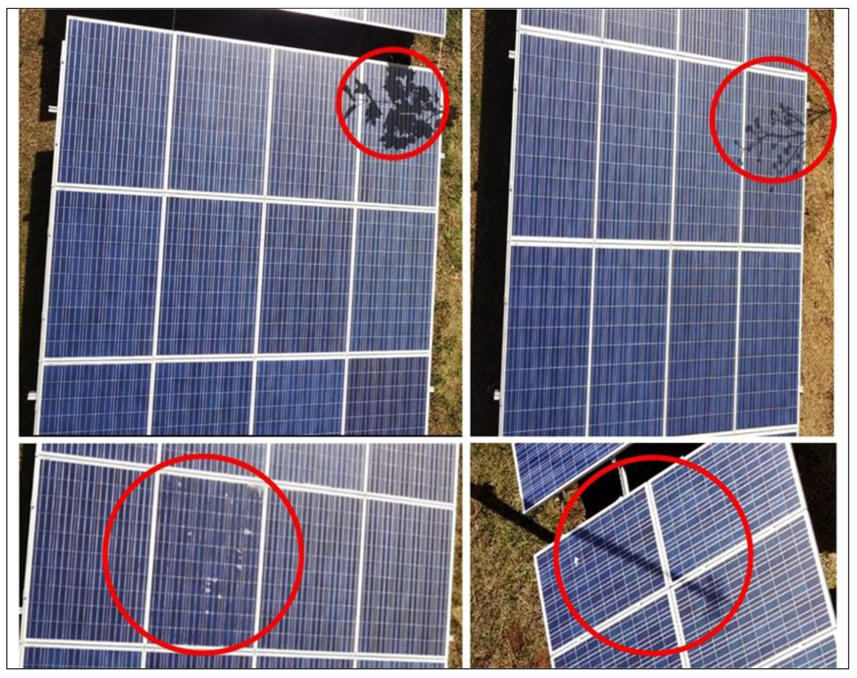
An analysis of the efficiency of performing neural network detection procedures depending on video recording modes showed that the optimal video recording parameters are a 1080p resolution with a frame rate of 30 FPS. This mode of video recording makes it possible to significantly speed up the processing of data by the neural network without reducing the quality of detection and increasing the power consumption of the UAV video camera. As a result of test flights and the video recording of the modules, it was possible to create a training set of more than 500 images (Figure 3). The training sample contains images of normal, shaded, and damaged modules, which is necessary to increase the quality of detection and minimize the number of false positives.
The next step after creating the training sample is its markup. The image labeling procedure is required to convert the sample data (images) into variables “understandable” for the neural network, which it can process and generalize [54]. For markup (annotation), the LabelImg (https://github.com/heartexlabs/labelImg, accessed on 28 August 2022) tool was used. Images of the training sample were manually labeled into two classes: “Normal_panel” and “Shaded_panel”. The first class includes images of photovoltaic modules with a normal (unshaded, clean, undamaged) surface. The second class includes images with problematic (shaded, dirty, damaged) photovoltaic modules.

3. Discussion

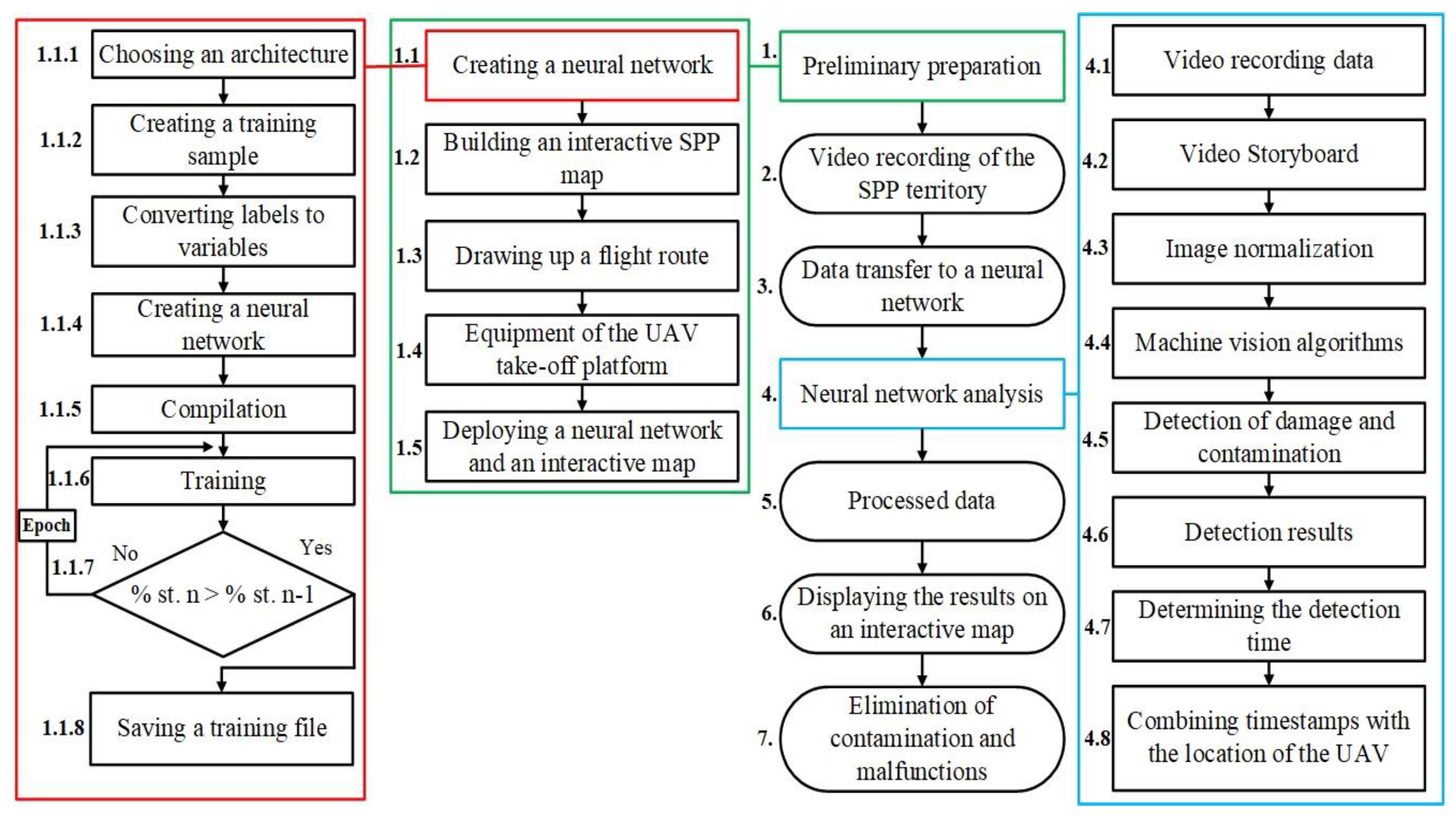
Thus, the creation of an automated complex is a multi-stage process, the general structure of which can be represented as a block diagram (Figure 4). The principle of its operation lies in the neural network analysis of video files captured by a UAV moving along the flight route above the photovoltaic modules. All captured data is analyzed to detect shading and damage to photovoltaic modules, which are then displayed on an interactive SPP map.
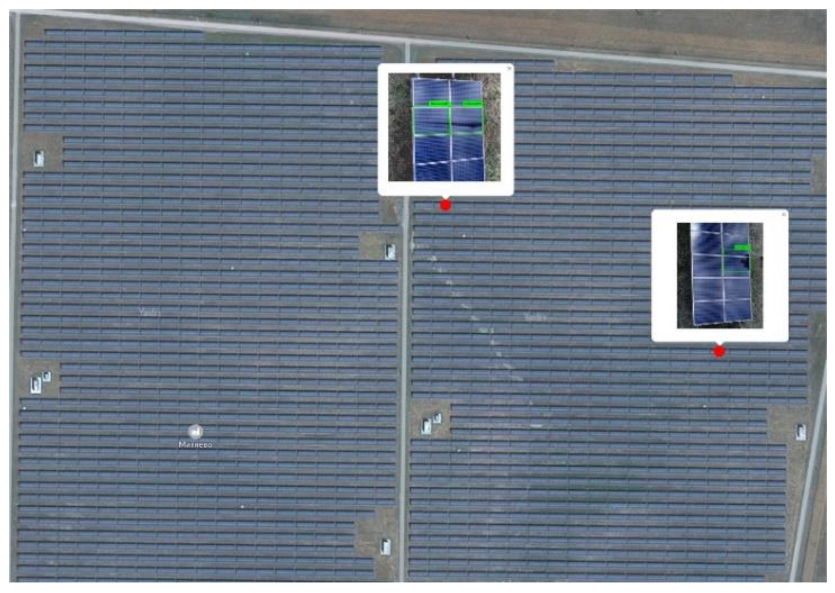
An interactive SPP map is generated based on the geotags taken by the UAV when flying around the territory of the station, and the detection time of problem areas is determined by the neural network. To build a map, the detection frame is synchronized with the time of the geotag, which makes it possible to determine the problematic photovoltaic module with an accuracy of several meters. All detected damages are marked on the map in the form of geotags with a photo of the detected damage. The output of geotags with the results of neural network analysis (photo of the module) allows the SPP dispatcher, being at his workplace, to determine the correctness of detection, as well as choose a way to eliminate the problem.
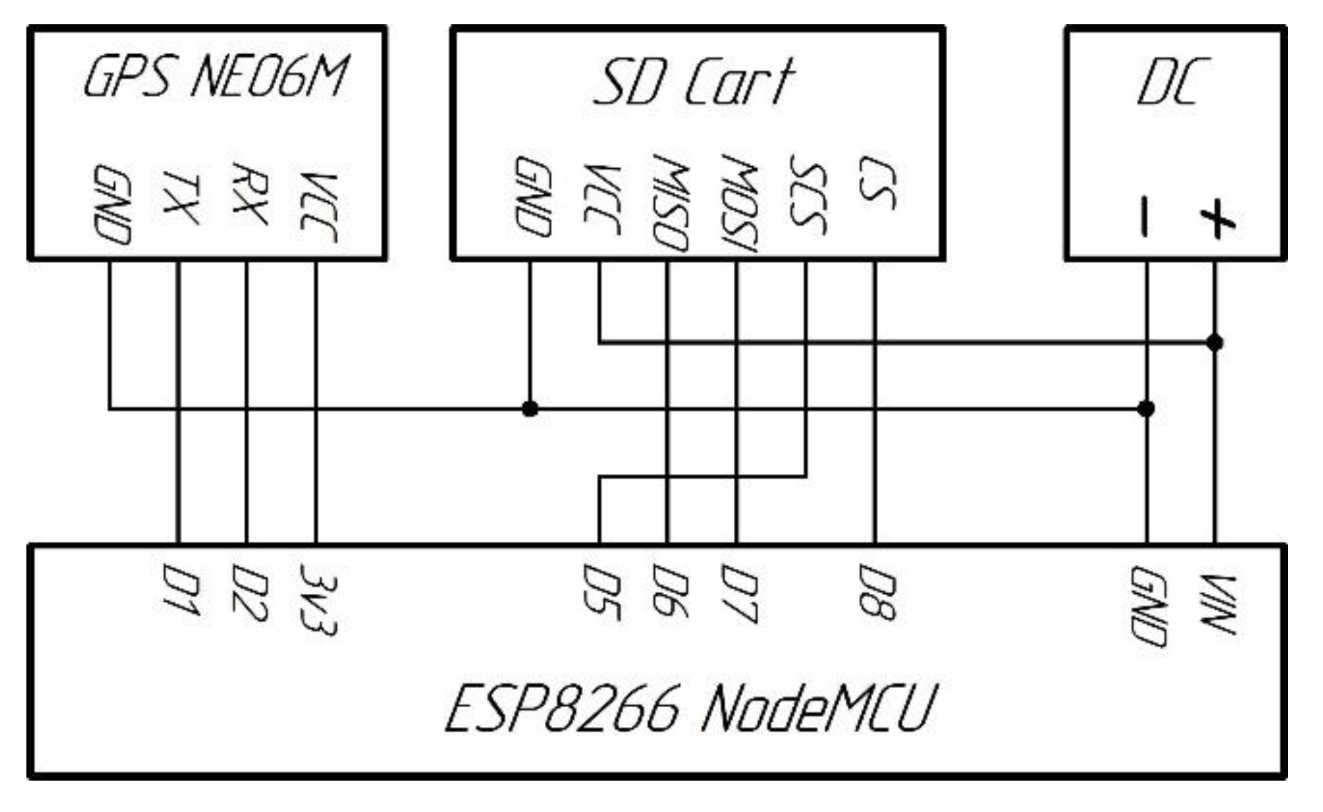
The process of displaying the detected problem areas of an industrial solar power plant on an interactive map is associated with fixing the UAV flight route, as well as outputting these data for further processing. The UAV has a GPS beacon that allows you to track their position on the map, as well as perform searches in the event of an emergency landing, but access to this data is limited by the licensed UAV software. Geotags and black box data decoding can be provided by the manufacturer after a request sent from the user’s personal account; however, during field tests and during a long debugging process, frequent requests are not practical. In view of this, it was decided to independently manufacture a GPS tracker and install it on the UAV as a payload. The block diagram of the GPS tracker is shown in Figure 5.
ESP8266 is used as the main microcontroller. To obtain geospatial information, the measuring module has a GPS receiver based on the NEO-6M-0-001 chip based on the Ublox NEO-6M STM chip. This module is a stand-alone GPS device with a high-performance u-blox 6 positioning processor. To communicate with the microcontroller, a UART (TTL) interface is used with a supported baud rate from 4800 to 230,400 baud, 9600 baud by default. Geotagged log is recorded on a micro-SD memory card. For this, a specialized micro SD card module is used, which is connected to the microcontroller via the SPI interface.
In order to determine the calculated effective performance of the complex (monitored by the installed capacity of SPP ( N ) by one complex), a mathematical model was developed that allows evaluating the capabilities of the proposed complex depending on the type of station and UAV, meteorological parameters, and computing equipment performance. In addition, the model allows you to calculate the minimum number of complexes required to ensure monitoring and diagnostics of the entire SPP, which is an important aspect of assessing the economic efficiency of the proposed solution. The value of the monitored power can be calculated from expression (1).
N = G P e k n 0 D W d t 2 l G n ,
where G is the coefficient taking into account the structural features of the supporting structures and the main characteristics of the modules, (W/m); P e is the performance of computing equipment; k n is the coefficient taking into account the frequency of UAV sorties; D is the daylight period, (s); W is the value of the UAV flight speed, taking into account the effect of wind, (m/s); l is the distance between the landing platform and the monitored row of the station, (m); n is the frequency of UAV departures.
The coefficient of structural features of the solar power plant and the main characteristics of photovoltaic modules ( G ) determining the power of the solar power plant section, over which the UAV flies in one second, is calculated from expression (2).
G = P Y h ,
where P is the rated power of the photovoltaic module, (W); Y is the type of supporting structure of the modules; h is the overall size of the module in the direction of the UAV movement (m).
The parameter ( P e ), which determines the computing power of the equipment, is calculated according to expression (3). It describes the processing speed of the captured data by the neural network and takes into account the time required to transfer data from the UAV memory to the computing device.
P e = 0.8 ( P N P r e f N ) 0.91 ,
where P N is the performance of computing equipment; P r e f N is the performance reference value.
The frequency of UAV departures ( n ) shows the number of sorties required to fly around the SPP territory per daylight hours (D), as well as the frequency of battery replacement, the value of which should take into account the climatic conditions in which the complex is operated. Calculated by Formula (4).
n = D d s t c k n ( 1 P e ) ,
where d s t c is the standard UAV battery discharge time, (s); k n is the frequency factor for UAV departures, taking into account climatic conditions.
The departure frequency factor is determined by expression (5).
k n = 1 ( ( 1.06 × 10 2 ) T 3.329 ) 2 ,
where T is the ambient temperature, (K).
The speed of the UAV under the influence of wind ( W ) is calculated from expression (6) [55].
W = 0.5 k ( V + C p ρ S u a v c o s ( ε ) U 3 m + V C p ρ S u a v c o s ( ε ) U 3 m ) ,
where k is a coefficient that takes into account the aerodynamic features of the UAV; V is UAV flight speed, (m/s); C p is UAV drag coefficient; ρ is air density, (kg/m3); S u a v is the UAV area exposed to wind, (m2); ε is the wind direction relative to the UAV motion vector, (degrees); U is wind speed, (m/s); m is the mass of the UAV, (kg).
The UAV flight speed is set to ensure the optimal quality of detection, taking into account the type of the supporting structure of the modules, and is calculated from expression (7).
V = 16.2   e x p ( 2.5 Q Y 0.03 ) ,
where Q is the set detection quality (0…1).
For a preliminary assessment of the technical and economic efficiency of the proposed solution, calculations were made of the energy losses of a photovoltaic installation operating in conditions of partial shading. The basic mathematical model was compiled on the basis of standard equations characterizing the operating mode of a uniformly illuminated photovoltaic installation with the serial switching of photovoltaic converters [56,57,58]. Based on this model, a system of equations was obtained that makes it possible to calculate the total power losses of a photovoltaic installation with uneven shading (8). The reliability of the compiled model was confirmed by experimental studies conducted in the laboratory “Renewable Energy” Sevastopol State University and the Sevastopol solar power plant [59].
{ P l o s s = U 1 m a x n p I 1 m a x U 1 m a x ( n p l I 1 + n p s I 2 ) , I 1 m a x = I p h I 0 [ e x p ( q ( U 1 m a x + I 1 m a x R s ) n s l ( A k T ) ) 1 ] , q ( U 1 m a x + I 1 m a x R s ) n s l ( A k T ) l n I 0 + I p h I 0 ( 1 + q ( U 1 m a x + I 1 m a x R s ) n s l ( A k T ) ) = 0 , I 1 = I p h I 0 e x p ( q ( U 2 m a x + I 1 R s ) n s l ( A k T ) ) , I 2 = n s s ( I p h I 0 e x p ( q ( U 2 m a x + I 2 R s + U d ) n s s ( A k T ) ) ) ,   a t   U 2 < U 2 m a x , I 2 = n s s ( I p h I 0 e x p ( q ( U 2 m a x + I 2 R s + U d ) n s l ( A k T ) ) ) ,   a t   U 2 U 2 m a x ,
where P l o s s is power losses from partial shading, (W); n p is the number of strings connected in parallel; U 1 m a x and U 2 m a x are voltage values at maximum power points (MPP) of strings connected in parallel, operating without shading and with shading, (V); I 1 m a x is the value of current in MPP strings without shading, (A); n p s is the number of shaded strings; n p l is the number of unshaded strings; I p h is the photocurrent of the shaded string, (A); I p h is the photocurrent of the illuminated string, (A); I 0 is reverse saturation current, (A); q is the electron charge, (C); R s is the series resistance of the module, (Ohm); n s l is the number of non-shunted solar cells in a string without shading; n s s is the number of non-shunted diode solar cells in a string with shading; A is the coefficient of the ideality of photocells in the module; k is the Boltzmann constant, (J/K); T is the temperature of the module photocells, (K); I 1 is the value of the current of the unshaded string at voltage U 2 m a x , (A); I 2 is the value of the current of the shaded string at voltage U 2 m a x , (A); U d is the voltage drop across the shunt diode, (V); U 2 ' is the string voltage with shunted groups of modules, (V).
The simulation results showed that, with the partial shading of two modules out of eighteen, the power loss of the string is about 50%; with the shading of one module, it is about 20%; with the shading of more than two modules, the power generation by the string is practically not performed (the value of the string current is limited by the current shaded photocells). The analysis of statistics reflecting the value of the probability of occurrence of partial shading at the SPP, in conjunction with the calculated data obtained as a result of mathematical modeling and the annual energy production of the SPP, showed that the timely identification and elimination of the causes leading to shading will increase the annual energy production of the SPP, which is about 2%, from which it follows that the solution proposed by the authors will reach the payback stage within a year and a half.

4. Results

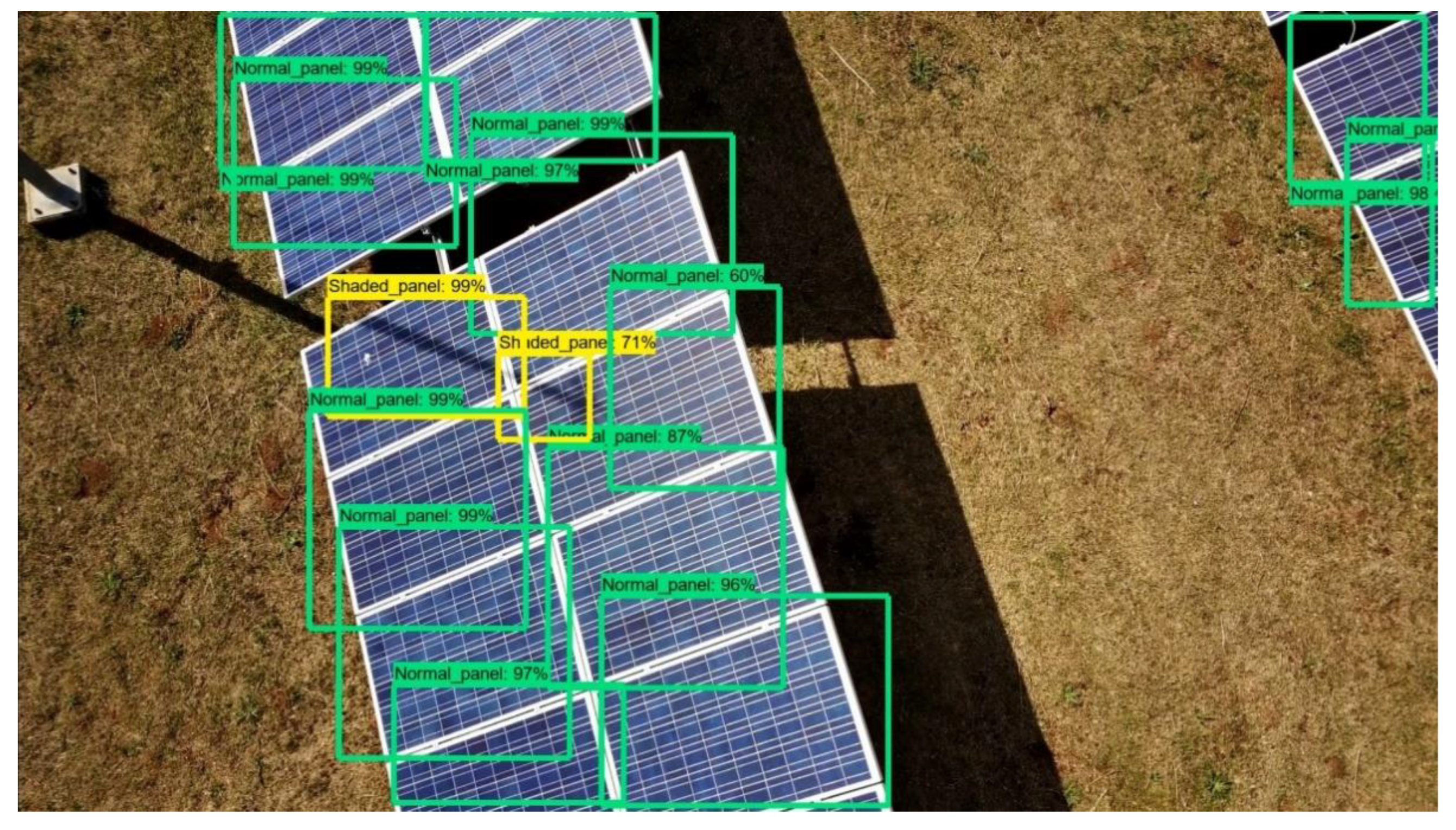
The results of the neural network processing of video materials obtained using the UAV camera are shown in Figure 6. Problem areas detected by the neural network on the surface of photovoltaic modules are visualized on the SPP interactive map (Figure 7).
A visual inspection of the recorded video materials on the tested section of the station with an area of 50,000 m2 showed that the accuracy of detecting problem areas by the neural network was 95%. Of the 20 shading and damage to the surfaces of the modules detected during visual inspection, an error was made only in one case.
The mathematical model proposed by the authors makes it possible to calculate the installed capacity of the solar power plant monitored by the complex, depending on various factors. This parameter determines the minimum number of automated systems required to monitor the entire station. The evaluation of the effectiveness of the proposed solution was carried out on the example of its use for monitoring the four-row solar photovoltaic station “Nikolaevka” with an installed capacity of 69.9 MW. The evaluation results showed that the use of a complex with a FIMI X8SE UAV and a computing device based on the GPU RTX2080 will allow monitoring up to 6.4 MW of installed power. Thus, about 11 complexes will be required to ensure the monitoring of this station.
In order to determine the technical and economic efficiency of using the complex at high-capacity solar power plants, calculations were made of the energy losses of photovoltaic modules as a result of their partial shading. The results of the calculations showed that, with the partial shading of two modules out of eighteen, the power losses of the string are about 50%; with the shading of one module, it is about 20%, and with the shading of three or more modules, the string practically does not generate energy (the value of the string current is limited by the current of the shaded photocells). Such a decrease in energy efficiency is due to the fact that the voltage values at the points of maximum string power with and without partial shading are not the same.
The analysis of the statistics of the occurrence of partial shading at the SPP, in conjunction with the calculated data obtained from the mathematical modeling of the annual power generation of the solar power plant and the real data of the station’s generation, showed that the timely identification and elimination of the causes leading to shading will increase the annual power generation of the solar power plant by a value of about 2%, from which it follows that the solution proposed by the authors will reach the payback stage within a year and a half.

5. Conclusions

The developed automated complex for monitoring and diagnosing photovoltaic modules allows solving the problem of the real-time monitoring of the state of a solar power plant. A distinctive feature of its use is the high speed and quality of detection of problem modules. Preliminary tests have shown that the classification accuracy is at least 95%. In addition, the advantages of the complex include the ease of implementation in existing industrial solar power plants. This is due to the fact that its functioning does not require additional structural changes in the existing design of the station. Feasibility studies for the implementation of this solution show that the use of the proposed complex will increase the energy efficiency of the power plant by 2% due to timely diagnostics and the prompt provision of information to maintenance personnel.
The mathematical model proposed by the authors makes it possible to calculate the installed capacity of the solar power plant monitored by the complex, depending on various factors. This parameter determines the minimum number of automated systems required to monitor the entire station. The evaluation of the effectiveness of the proposed solution was carried out on the example of its use for monitoring the four-row solar photovoltaic station “Nikolaevka” with an installed capacity of 69.9 MW. The evaluation results showed that the use of a complex with a FIMI X8SE UAV and a computing device based on the GPU RTX2080 will allow monitoring up to 6.4 MW of installed power. Thus, about 11 complexes will be required to ensure the monitoring of this station.

Author Contributions

Conceptualization, P.K. and D.K.; formal analysis, V.P., V.B. and M.J.; methodology, P.K., D.K. and L.Y.; supervision, L.Y., M.J. and A.F.; validation, D.K., V.P. and V.B.; visualization, D.K., P.K. and V.P.; writing—original draft, P.K. and D.K.; writing—review and editing, D.K., V.B. and A.F. All authors have read and agreed to the published version of the manuscript.

Funding

This research received no external funding.

Institutional Review Board Statement

Not applicable.

Informed Consent Statement

Not applicable.

Data Availability Statement

Not applicable.

Conflicts of Interest

The authors declare no conflict of interest.

References

  1. Silverman, T.J.; Mansfield, L.; Repins, I.; Kurtz, S. Damage in Monolithic Thin-Film Photovoltaic Modules Due to Partial Shade. IEEE J. Photovolt. 2016, 6, 1333–1338. [Google Scholar] [CrossRef]
  2. Paul, D.I. Dust Deposition on Photovoltaic Modules: Its Effects on Performance. In The Effects of Dust and Heat on Photovoltaic Modules: Impacts and Solutions; Springer: Berlin/Heidelberg, Germany, 2022; pp. 3–46. [Google Scholar]
  3. Al Siyabi, I.; Al Mayasi, A.; Al Shukaili, A.; Khanna, S. Effect of Soiling on Solar Photovoltaic Performance under Desert Climatic Conditions. Energies 2021, 14, 659. [Google Scholar] [CrossRef]
  4. Kuznetsov, P.; Yuferev, L.; Voronin, D.; Panchenko, V.A.; Jasiński, M.; Najafi, A.; Leonowicz, Z.; Bolshev, V.; Martirano, L. Methods Improving Energy Efficiency of Photovoltaic Systems Operating under Partial Shading. Appl. Sci. 2021, 11, 10696. [Google Scholar] [CrossRef]
  5. Nalamwar, H.S.; Ivanov, M.A.; Baidali, S.A. Automated Intelligent Monitoring and the Controlling Software System for Solar Panels. J. Phys. Conf. Ser. 2017, 803, 012107. [Google Scholar] [CrossRef]
  6. Kuznetsov, P.N.; Lyamina, N.V.; Yuferev, L.Y. A Device for Remote Monitoring of Solar Power Plant Parameters. Appl. Sol. Energy 2019, 55, 247–251. [Google Scholar] [CrossRef]
  7. Kumar, N.M.; Sudhakar, K.; Samykano, M.; Jayaseelan, V. On the Technologies Empowering Drones for Intelligent Monitoring of Solar Photovoltaic Power Plants. Procedia Comput. Sci. 2018, 133, 585–593. [Google Scholar] [CrossRef]
  8. Kuznetsov, P.N.; Kotelnikov, D.Y. Automated Complex of Intelligent Monitoring of a Solar Power Plant. J. Phys. Conf. Ser. 2021, 2094, 052025. [Google Scholar] [CrossRef]
  9. Tina, G.M.; Cosentino, F.; Ventura, C. Monitoring and Diagnostics of Photovoltaic Power Plants. In Renewable Energy in the Service of Mankind; Springer International Publishing: Cham, Switzerland, 2016; Volume II, pp. 505–516. [Google Scholar]
  10. Coleman, A.; Zalewski, J. Intelligent Fault Detection and Diagnostics in Solar Plants. In Proceedings of the 6th IEEE International Conference on Intelligent Data Acquisition and Advanced Computing Systems, Prague, Czech Republic, 15–17 September 2011; IEEE: Piscataway, NJ, USA, 2011; pp. 948–953. [Google Scholar]
  11. Beránek, V.; Olšan, T.; Libra, M.; Poulek, V.; Sedláček, J.; Dang, M.-Q.; Tyukhov, I. New Monitoring System for Photovoltaic Power Plants’ Management. Energies 2018, 11, 2495. [Google Scholar] [CrossRef]
  12. Libra, M.; Daneček, M.; Lešetický, J.; Poulek, V.; Sedláček, J.; Beránek, V. Monitoring of Defects of a Photovoltaic Power Plant Using a Drone. Energies 2019, 12, 795. [Google Scholar] [CrossRef]
  13. Jayas, D.S.; Paliwal, J.; Visen, N.S. Review Paper (AE—Automation and Emerging Technologies). J. Agric. Eng. Res. 2000, 77, 119–128. [Google Scholar] [CrossRef] [Green Version]
  14. Sietsma, J.; Dow, R.J.F. Creating Artificial Neural Networks That Generalize. Neural Netw. 1991, 4, 67–79. [Google Scholar] [CrossRef]
  15. Sarle, W.S. Neural networks and statistical models. In Proceedings of the Nineteenth Annual SAS Users Group International Conference, Dallas, TX, USA, 10–13 April 1994; SAS Institute Inc.: Cary, NC, USA, 1994; pp. 1538–1550. [Google Scholar]
  16. Kalogirou, S.A. Artificial Neural Networks in Renewable Energy Systems Applications: A Review. Renew. Sustain. Energy Rev. 2001, 5, 373–401. [Google Scholar] [CrossRef]
  17. Kalogirou, S.A. Applications of Artificial Neural-Networks for Energy Systems. Appl. Energy 2000, 67, 17–35. [Google Scholar] [CrossRef]
  18. Mo, K.; Lee, S.J.; Seong, P.H. A Dynamic Neural Network Aggregation Model for Transient Diagnosis in Nuclear Power Plants. Prog. Nucl. Energy 2007, 49, 262–272. [Google Scholar] [CrossRef]
  19. Guo, Y.; Gong, C.; Zeng, H.-Y. The Application of Artificial Neural Network in Nuclear Energy. In Proceedings of the 2010 International Conference on Machine Learning and Cybernetics, Qingdao, China, 11–14 July 2010; IEEE: Piscataway, NJ, USA, 2010; pp. 1244–1248. [Google Scholar]
  20. Ferrero Bermejo, J.; Gómez Fernández, J.F.; Olivencia Polo, F.; Crespo Márquez, A. A Review of the Use of Artificial Neural Network Models for Energy and Reliability Prediction. A Study of the Solar PV, Hydraulic and Wind Energy Sources. Appl. Sci. 2019, 9, 1844. [Google Scholar] [CrossRef]
  21. El-Abbasy, M.S.; Senouci, A.; Zayed, T.; Mirahadi, F.; Parvizsedghy, L. Artificial Neural Network Models for Predicting Condition of Offshore Oil and Gas Pipelines. Autom. Constr. 2014, 45, 50–65. [Google Scholar] [CrossRef]
  22. Tao, X.; Zhang, D.; Wang, Z.; Liu, X.; Zhang, H.; Xu, D. Detection of Power Line Insulator Defects Using Aerial Images Analyzed with Convolutional Neural Networks. IEEE Trans. Syst. Man Cybern. Syst. 2020, 50, 1486–1498. [Google Scholar] [CrossRef]
  23. Schlechtingen, M.; Ferreira Santos, I. Comparative Analysis of Neural Network and Regression Based Condition Monitoring Approaches for Wind Turbine Fault Detection. Mech. Syst. Signal Process. 2011, 25, 1849–1875. [Google Scholar] [CrossRef]
  24. Movsessian, A.; García Cava, D.; Tcherniak, D. An Artificial Neural Network Methodology for Damage Detection: Demonstration on an Operating Wind Turbine Blade. Mech. Syst. Signal Process. 2021, 159, 107766. [Google Scholar] [CrossRef]
  25. Munawar, H.S.; Ullah, F.; Qayyum, S.; Khan, S.I.; Mojtahedi, M. UAVs in Disaster Management: Application of Integrated Aerial Imagery and Convolutional Neural Network for Flood Detection. Sustainability 2021, 13, 7547. [Google Scholar] [CrossRef]
  26. Valdez, D.B.; Godmalin, R.A.G. A Deep Learning Approach of Recognizing Natural Disasters on Images Using Convolutional Neural Network and Transfer Learning. In Proceedings of the International Conference on Artificial Intelligence and Its Applications, EL-Oued, Algeria, 28–30 September 2021; ACM: New York, NY, USA, 2021; pp. 1–7. [Google Scholar]
  27. Huerta Herraiz, Á.; Pliego Marugán, A.; García Márquez, F.P. Photovoltaic Plant Condition Monitoring Using Thermal Images Analysis by Convolutional Neural Network-Based Structure. Renew. Energy 2020, 153, 334–348. [Google Scholar] [CrossRef]
  28. Haidari, P.; Hajiahmad, A.; Jafari, A.; Nasiri, A. Deep Learning-Based Model for Fault Classification in Solar Modules Using Infrared Images. Sustain. Energy Technol. Assess. 2022, 52, 102110. [Google Scholar] [CrossRef]
  29. Sohani, A.; Sayyaadi, H.; Miremadi, S.R.; Samiezadeh, S.; Doranehgard, M.H. Thermo-Electro-Environmental Analysis of a Photovoltaic Solar Panel Using Machine Learning and Real-Time Data for Smart and Sustainable Energy Generation. J. Clean. Prod. 2022, 353, 131611. [Google Scholar] [CrossRef]
  30. Alajmi, M.; Aljasem, O.; Ali, N.; Alqurashi, A.; Abdel-Qader, I. Fault Detection and Localization in Solar Photovoltaic Arrays Framework: Hybrid Methods of Data-Analysis and a Network of Voltage-Current Sensors. In Proceedings of the 2018 IEEE International Conference on Electro/Information Technology (EIT), Rochester, MI, USA, 3–5 May 2018; IEEE: Piscataway, NJ, USA, 2018; pp. 404–410. [Google Scholar]
  31. Samara, S.; Natsheh, E. Intelligent Real-Time Photovoltaic Panel Monitoring System Using Artificial Neural Networks. IEEE Access 2019, 7, 50287–50299. [Google Scholar] [CrossRef]
  32. Hu, Y.; Zhang, J.; Cao, W.; Wu, J.; Tian, G.Y.; Finney, S.J.; Kirtley, J.L. Online Two-Section PV Array Fault Diagnosis with Optimized Voltage Sensor Locations. IEEE Trans. Ind. Electron. 2015, 62, 7237–7246. [Google Scholar] [CrossRef]
  33. Chine, W.; Mellit, A.; Lughi, V.; Malek, A.; Sulligoi, G.; Massi Pavan, A. A Novel Fault Diagnosis Technique for Photovoltaic Systems Based on Artificial Neural Networks. Renew. Energy 2016, 90, 501–512. [Google Scholar] [CrossRef]
  34. Lopez-Guede, J.M.; Ramos-Hernanz, J.A.; Zulueta, E.; Fernadez-Gamiz, U.; Oterino, F. Systematic Modeling of Photovoltaic Modules Based on Artificial Neural Networks. Int. J. Hydrogen Energy 2016, 41, 12672–12687. [Google Scholar] [CrossRef]
  35. Ali, R.; Kang, D.; Suh, G.; Cha, Y.-J. Real-Time Multiple Damage Mapping Using Autonomous UAV and Deep Faster Region-Based Neural Networks for GPS-Denied Structures. Autom. Constr. 2021, 130, 103831. [Google Scholar] [CrossRef]
  36. Ayoub, N.; Schneider-Kamp, P. Real-Time On-Board Deep Learning Fault Detection for Autonomous UAV Inspections. Electronics 2021, 10, 1091. [Google Scholar] [CrossRef]
  37. Xun, D.T.; Lim, Y.L.; Srigrarom, S. Drone Detection Using YOLOv3 with Transfer Learning on NVIDIA Jetson TX2. In Proceedings of the 2021 Second International Symposium on Instrumentation, Control, Artificial Intelligence, and Robotics (ICA-SYMP), Bangkok, Thailand, 20–22 January 2021; IEEE: Piscataway, NJ, USA, 2021; pp. 1–6. [Google Scholar]
  38. Chen, Y.M.; Dong, L.; Oh, J.-S. Real-Time Video Relay for UAV Traffic Surveillance Systems Through Available Communication Networks. In Proceedings of the 2007 IEEE Wireless Communications and Networking Conference, Hong Kong, China, 11–15 March 2007; pp. 2608–2612. [Google Scholar]
  39. Pereira, F.C.; Pereira, C.E. Embedded Image Processing Systems for Automatic Recognition of Cracks Using UAVs. IFAC Pap. Online 2015, 48, 16–21. [Google Scholar] [CrossRef]
  40. Halawa, H.; Abdelhafez, H.A.; Boktor, A.; Ripeanu, M. NVIDIA Jetson Platform Characterization. In Proceedings of the 23rd International Conference on Parallel and Distributed Computing, Santiago de Compostela, Spain, 28 August–1 September 2017; pp. 92–105. [Google Scholar]
  41. Suzen, A.A.; Duman, B.; Sen, B. Benchmark Analysis of Jetson TX2, Jetson Nano and Raspberry PI Using Deep-CNN. In Proceedings of the 2020 International Congress on Human-Computer Interaction, Optimization and Robotic Applications (HORA), Ankara, Turkey, 26–28 June 2020; IEEE: Piscataway, NJ, USA, 2020; pp. 1–5. [Google Scholar]
  42. Bokovoy, A.; Muravyev, K.; Yakovlev, K. Real-Time Vision-Based Depth Reconstruction with NVidia Jetson. In Proceedings of the 2019 European Conference on Mobile Robots (ECMR), Prague, Czech Republic, 4–6 September 2019; IEEE: Piscataway, NJ, USA, 2019; pp. 1–6. [Google Scholar]
  43. Zoev, I.V.; Markov, N.G.; Ryzhova, S.E. Intelligent Computer Vision System for Unmanned Aerial Vehicles for Monitoring Technological Objects of Oil and Gas Industry. Bull. Tomsk Polytech. Univ. Geo Assets Eng. 2019, 330, 34–49. [Google Scholar] [CrossRef]
  44. Aposporis, P. Object Detection Methods for Improving UAV Autonomy and Remote Sensing Applications. In Proceedings of the 2020 IEEE/ACM International Conference on Advances in Social Networks Analysis and Mining (ASONAM), The Hague, The Netherlands, 7–10 December 2020; IEEE: Piscataway, NJ, USA, 2020; pp. 845–853. [Google Scholar]
  45. Ampatzidis, Y.; Partel, V.; Costa, L. Agroview: Cloud-Based Application to Process, Analyze and Visualize UAV-Collected Data for Precision Agriculture Applications Utilizing Artificial Intelligence. Comput. Electron. Agric. 2020, 174, 105457. [Google Scholar] [CrossRef]
  46. Russakovsky, O.; Deng, J.; Su, H.; Krause, J.; Satheesh, S.; Ma, S.; Huang, Z.; Karpathy, A.; Khosla, A.; Bernstein, M.; et al. ImageNet Large Scale Visual Recognition Challenge. Int. J. Comput. Vis. 2015, 115, 211–252. [Google Scholar] [CrossRef]
  47. Zhang, Y.; Yuan, Y.; Feng, Y.; Lu, X. Hierarchical and Robust Convolutional Neural Network for Very High-Resolution Remote Sensing Object Detection. IEEE Trans. Geosci. Remote Sens. 2019, 57, 5535–5548. [Google Scholar] [CrossRef]
  48. Wang, Z.; Liu, J. A Review of Object Detection Based on Convolutional Neural Network. In Proceedings of the 2017 36th Chinese Control Conference (CCC), Dalian, China, 26–28 July 2017; IEEE: Piscataway, NJ, USA, 2017; pp. 11104–11109. [Google Scholar]
  49. Fang, W.; Wang, L.; Ren, P. Tinier-YOLO: A Real-Time Object Detection Method for Constrained Environments. IEEE Access 2020, 8, 1935–1944. [Google Scholar] [CrossRef]
  50. Dai, J.; Li, Y.; He, K.; Sun, J. R-FCN: Object Detection via Region-Based Fully Convolutional Networks. In Proceedings of the 30th Annual Conference on Neural Information Processing Systems 2016, Barcelona, Spain, 5–10 December 2016. [Google Scholar]
  51. Website: GitHub. Available online: https://github.com/tensorflow/models/blob/master/research/object_detection/g3doc/tf1_detection_zoo.md (accessed on 30 August 2022).
  52. Yang, C.; Xie, L.; Qiao, S.; Yuille, A.L. Training Deep Neural Networks in Generations: A More Tolerant Teacher Educates Better Students. Proc. AAAI Conf. Artif. Intell. 2019, 33, 5628–5635. [Google Scholar] [CrossRef]
  53. Rawat, W.; Wang, Z. Deep Convolutional Neural Networks for Image Classification: A Comprehensive Review. Neural Comput. 2017, 29, 2352–2449. [Google Scholar] [CrossRef]
  54. Tian, Y.; Gelernter, J.; Wang, X.; Chen, W.; Gao, J.; Zhang, Y.; Li, X. Lane Marking Detection via Deep Convolutional Neural Network. Neurocomputing 2018, 280, 46–55. [Google Scholar] [CrossRef]
  55. Kuznetsov, P.; Kotelnikov, D. Automated System for Solar Power Plant Intelligent Monitoring. Energy Saf. Energy Econ. 2021, 6, 39–45. [Google Scholar] [CrossRef]
  56. Mahmoud, Y.; Xiao, W.; Zeineldin, H.H. A Simple Approach to Modeling and Simulation of Photovoltaic Modules. IEEE Trans. Sustain. Energy 2012, 3, 185–186. [Google Scholar] [CrossRef]
  57. Rauschenbach, H.S. Solar Cell Array Design Handbook: The Principles and Technology of Photovoltaic Energy Conversion; Springer Science & Business Media: Berlin/Heidelberg, Germany, 2012. [Google Scholar]
  58. Kumari, J.S.; Babu, C. Mathematical Modeling and Simulation of Photovoltaic Cell Using Matlab-Simulink Environment. Int. J. Electr. Comput. Eng. IJECE 2011, 2, 26–34. [Google Scholar] [CrossRef]
  59. Kuznetsov, P.; Abd, A.; Kuvshinov, V.; Issa, H.; Mohammed, H.; Al-bairmani, A. Investigation of the Losses of Photovoltaic Solar Systems during Operation under Partial Shading. J. Appl. Eng. Sci. 2020, 18, 313–320. [Google Scholar] [CrossRef]
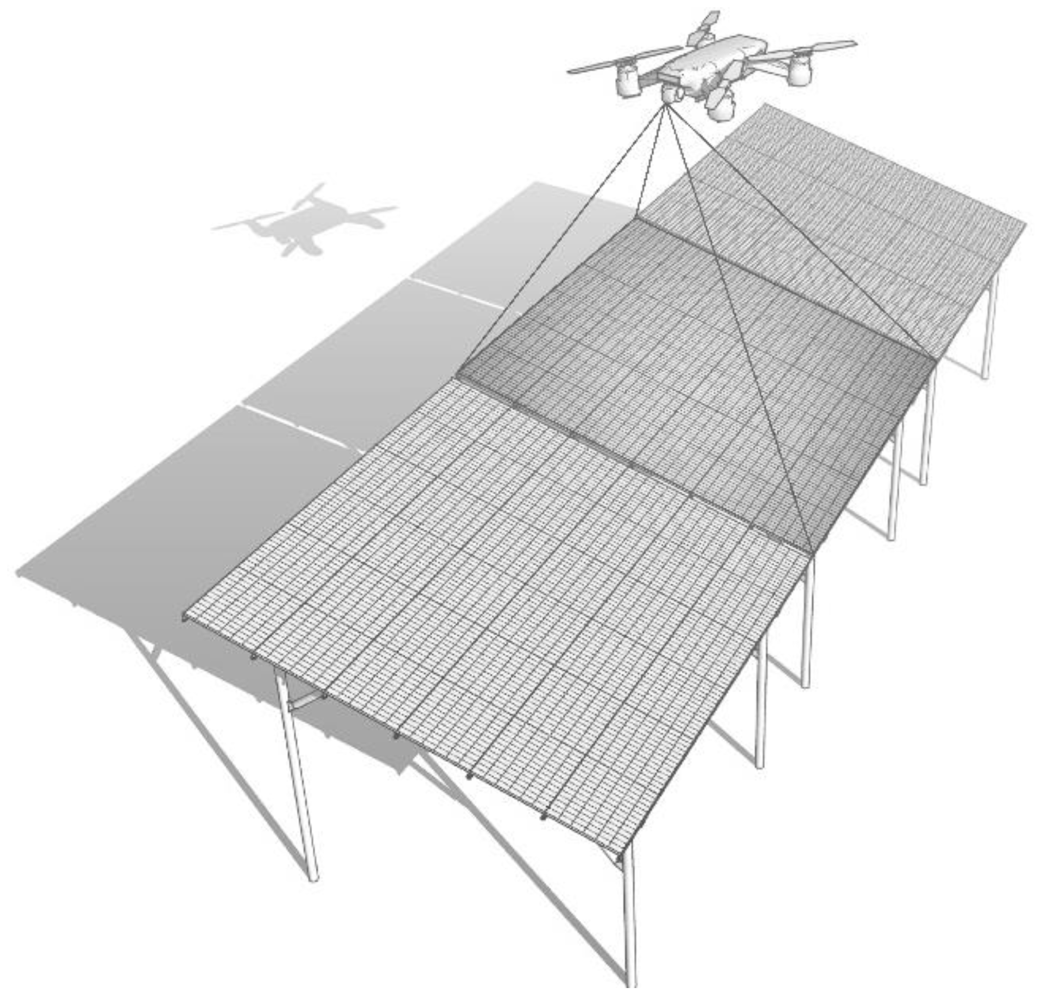
Figure 1. An example of a video recording scheme for UAV photovoltaic modules.
Sustainability 14 11930 g001
Figure 2. Testing of an automated complex on industrial SPP: (a)—SPP “Carrier”; (b)—SPP “Nikolaevka”.
Sustainability 14 11930 g002
Figure 3. Examples of images of problem modules from the training sample.
Sustainability 14 11930 g003
Figure 4. Algorithm for the implementation of the automated complex: (Red is creation of a neural network; Green is preliminary preparation for the operation of the complex; Blue is neural network analysis).
Sustainability 14 11930 g004
Figure 5. Structural diagram of a GPS tracker.
Sustainability 14 11930 g005
Figure 6. A frame with the result of a neural network classification of the surface state of photovoltaic modules.
Sustainability 14 11930 g006
Figure 7. An example of an interactive map output.
Sustainability 14 11930 g007
Table 1. Qualitative evaluation of the methods.
MethodSpeed of OperationDetection AccuracyInformation of the ProblemCostImplementation Complexity
Thermographic methodSlowMediumLowHighEasy
Electrical data analysisFastHighLowHighHard
Simulation modelingFastLowLowMediumMedium
Proposed methodNormalMediumHighLowEasy
Table 2. The speed of data analysis by the neural networks of various architectures [51].
ArchitectureTime, msAccuracy, %Score
SSDLite MobileNet v2 COCO27535/90
SSD Inception v2 COCO42656/88.8
Faster R-CNN Inception v2 COCO58941/111.2
Faster R-CNN ResNet101 COCO106864/95.4
Faster R-CNN Resnet101 lowproposals COCO82757/87.2
Faster R-CNN Inception ResNet v2 atrous COCO6206011/61.6
Faster R-CNN Inception ResNet v2 atrous2417110/75.1
lowproposals COCO1833868/86.5
Faster R-CNN nas540829/83.9
Faster R-CNN nas lowproposals COCO84992/110.9
YOLOv31101003/109.1
Inception v327535/90
Publisher’s Note: MDPI stays neutral with regard to jurisdictional claims in published maps and institutional affiliations.