Article

Mechanical Characteristics of the Combination System of Medium-Diameter Anti-Slide Piles and Tunnel-Under-Landslide Loading

1
Institute of Systems Engineering, China Academy of Engineering Physics, Mianyang 621010, China
2
School of Civil Engineering and Architecture, Southwest University of Science and Technology, Mianyang 621010, China
3
Applied Science, Hong Kong Baptist University, Sha Tin, New Territories, Hong Kong 999077, China
*
Author to whom correspondence should be addressed.
Sustainability 2022, 14(19), 12135; https://doi.org/10.3390/su141912135
Submission received: 13 July 2022 / Revised: 31 August 2022 / Accepted: 17 September 2022 / Published: 25 September 2022

Abstract

:
Landslides have significant impacts on the stress and deformation of existing tunnel that can damage the existing tunnel lining structures and thus affect normal traffic operation. It is of importance to study the mechanical mechanism of tunnel–landslide support systems. However, there are few studies on the mechanical mechanism of existing tunnels in landslide areas. The combination of medium-diameter anti-slide piles (300 mm ≤ D ≤ 800 mm) overcomes the disadvantages of the complex construction process and higher site requirements for large-diameter anti-slide piles (D > 800 mm) and the disadvantage of lower support with micro anti-slide piles (D < 300 mm). In this study, considering the influence of landslides on existing tunnel deformation, a new type of medium-diameter anti-slide pile reinforcement system for existing tunnels is proposed based on the Nanping Tunnel project. In order to study the influence of pile spacing on tunnel support, first, the maximum pile spacing of 12.5 d (25 cm) was calculated by the mathematical geometric method, and then, three physical models were established for experimental comparison and analysis, including three different spacing cases of 7.5 d (15 cm), 10 d (20 cm), and 12.5 d (25 cm). In addition, numerical simulation was used to analyze the landslide and tunnel deformation under three pile spacing working conditions. The following conclusions are reached: As the distance between the combined pile increased, the deformation of the pile body and the tunnel lining structure also increased gradually, and the earth pressure and bending moments acting on the tunnel and the pile body increased progressively. However, when the pile spacing was increased from 7.5 d to 10 d, the increase in tunnel bending moment (52.9% increase in tunnel lining moment) was much more significant than when the pile spacing was increased from 10 d to 12.5 d (28.1% increase in tunnel lining moment). The results showed that if the landslide thrust is small, the pile spacing can be increased to 12.5 d or more in the design of combined medium-diameter anti-slide piles; if the landslide thrust is large, the pile spacing should be reduced to 7.5 d or less. Whether the landslide’s thrust is large or small, the combined medium-diameter anti-slide piles with a 10 d pile spacing are less cost-effective for landslide control. The new combined medium-diameter anti-slide piles have high loading capacity and stability, which can further improve the strength of existing tunnels.

1. Introduction

With the rapid development of transportation infrastructures around the world, more and more railways and roads are required to pass through mountainous areas. Thus, specific tunnel–landslide systems are formed. Because of the particular engineering characteristics of tunnel–landslide system and complex deformation mechanism, it has been a hot issue for research. To ensure the safety of tunnel lining structures, some scholars have achieved certain research results [1,2].
The tunnel–landslide system has a complex topography and large longitudinal and transverse variations of the landslide body. In engineering construction, reasonable tunnel reinforcement measures have been a hot spot for research. The main focus of the current research for existing tunnel–landslide projects is on the following areas; First, the tunnel–landslide type is divided into orthogonal, oblique, and parallel, depending on the relationship between the intersection of the tunnel axis and the main slide direction line of the landslide [3]. Second, to study tunnel–landslide’s force characteristics under different working conditions, using numerical simulation, field monitoring, and experimental research methods. In recent years, due to the significant improvement of computer technology, numerical simulation means have more tremendous advantages in dealing with complex soil environments and problematic tunnel–landslide force and deformation characteristics. Therefore, numerical simulations are used more frequently in studying complex operating conditions [4,5,6,7,8,9,10,11], and analyze tunnel force and deformation characteristics under landslide conditions using finite elements or discrete elements. Although numerical simulation means developed rapidly, for the complex actual working conditions, there is still a certain gap in the accuracy of the simulation. Generally, using the field monitoring method can get more accurate data. Y. Zhang et al. (2015) [12] for landslide hazards induced by tunnel excavation, the construction-induced landslide damage to the tunnel is simulated using field monitoring data, and new support means are proposed. Causse L et al. (2015) [13] and Li Z et al. (2014) [14] have further analyzed the damage to the tunnel structure due to slope slides and landslides parallel to the tunnel during creep in the case of deeply buried tunnels. Li P et al. (2019) [15] analyzed the impact on construction practices after tunneling under hilly terrain and commented on tunneling under this working condition. Field monitoring methods are generally not of general research value for specific projects. In order to address the limitations of field monitoring means, model test methods are generally used for verification. The model test method is based on the principle of similarity, which can better reflect the mechanical phenomena in engineering and is more convenient for researchers to collect test data. In the model test method, Sao J et al. (2021) [16] used model tests to investigate further the bias of the tunnel–landslide system at different slide zone angles and concluded the tunnel bias ratio decreases when the slide zone angle gradually increases. Tian X et al. (2021) [17] aimed at the tunnel landslide system; in tunnel excavation and control, the tunnel under different support conditions generated different stress and deformation conditions. Zhang Z et al. (2022) [18] for longitudinal tunnels, the distribution of bending moment and earth pressure in tunnels under the action of landslide thrust using anti-slide piles and anchor cables. Third, in further research on the control methods of the tunnel–landslide system, Li T et al. (2021) [1] analyze the tunnel force characteristics under different pile spacing conditions and derive the optimal anti-slide pile support spacing in the orthogonal tunnel–landslide system. Tian, S. et al. (2021) [19] proposed means of over-support, pre-stressed anchor cable, etc., actively changing the tunnel surrounding rock stress as the core of the method to reduce the damage of landslides on the tunnel system. Some scholars [11,20,21,22,23] study on the interaction mechanism between landslide body and tunnel under anchor cable reinforcement and anti-slide pile support in the existing tunnel in the mountainous landslide area.
In summary, despite the research on landslides caused due to tunnel excavation conducted by the scholars above, there is still a lack of research on the influence of landslide sliding on existing tunnels. In especially, there is less research on the reinforcement mechanism of existing tunnels using new combinations of medium-diameter anti-slide piles. This study proposes a new combined medium-diameter anti-slide pile reinforcement system, including lining and combined medium-diameter anti-slide piles. The combined medium-diameter anti-slide pile (300 mm ≤ D ≤ 800 mm) [24] overcomes the disadvantages of the complex construction process, high cost, and high site requirements for large-diameter anti-slide piles (D > 800 mm). At the same time, it also overcomes the disadvantages of the poor support effect of miniature anti-slide piles (D < 300 mm). In this paper, the combination of medium-diameter anti-slide piles consists of three round piles of 600 mm diameter distributed in a triangular shape. The anti-slide piles are the front piles near the tunnel side and the back piles near the landslide side. At the same time, it is considered that when the pile spacing is too small, although it can reduce the sliding tendency of the slope, it cannot give full play to the bearing capacity of the pile. When the pile spacing is too large, it cannot meet the slope anti-sliding requirements leading to landslides affecting the tunnel. In particular, a reasonable pile spacing design is crucial when the tunnel interacts with the pile. Therefore, the maximum pile spacing calculation model was constructed based on the mathematical method in the article of Zhao, T. Y. et al. (2022) [25,26] to simplify the calculation of the landslide model in this paper, which resulted in a maximum pile spacing of 12.5 d. Therefore, in this paper, model tests combined with numerical simulation methods are used [27,28] to investigate further the combined medium-diameter force characteristics of the anti-slide pile-tunnel system under three different pile spacing (7.5 d, 10 d, 12.5 d). Using the Nanping Tunnel of Da-zhun Railway as the engineering prototype, we analyze the influence of anti-slide pile spacing on tunnel support. In contrast, reasonable pile spacing is further optimization of construction cost.

2. Project Description

2.1. Engineering Background

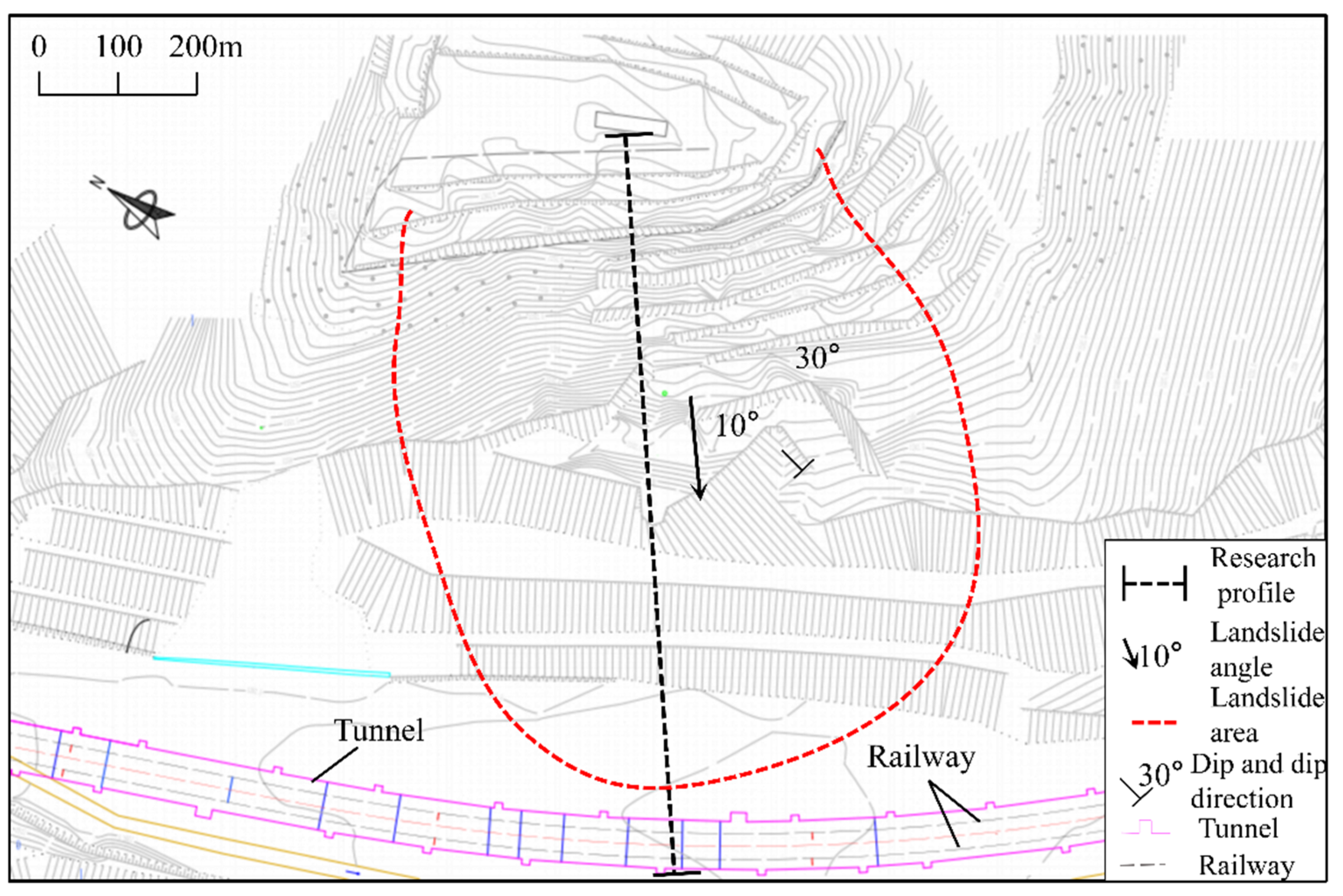
This paper uses the Nanping Tunnel of the Da-zhun Railway as the research prototype. The Nanping Tunnel is located on the south side of Junghar Banner. It is is between Diandaigou Station and Yaogou Station of Da-zhun Railway, as shown in Figure 1. The terrain slopes from northwest to southeast, and the altitude is 1100 m~1300 m. The surface is largely covered by the Quaternary aeolian sand and loess layers, with sparse vegetation and strong terrain cutting, which is a typical hilly and gully area. Nanping Tunnel is an underground excavation from the tunnel entrance to 70 m, and the rest is backfilled after the excavation of myeongdong. It was completed and put into operation in 2008. The import mileage is DK16 + 575, the export mileage is DK17 + 120, and the total length is 545 m, as shown in Figure 2.

2.2. Geological Boreholes

The Nanping Tunnel is on a gentle slope in front of a low-medium mountainous area, with large undulating terrain and developed gullies. The entrance of the tunnel is located on a soil hill. The mountain’s surface is covered with loess, with a thickness of about 2 m. The lower bedrock is exposed, and the exit end is covered with the loess. The mileage DK16 + 765 of the tunnel is a ravine. There is little vegetation in the ditch, and the weathering is serious. The tunnel is buried at a depth of 12.2 m. The tunnel passes through the middle of the two hills pass highlands. The groundwater in the pass section (DK16 + 570~DK17 + 020) is relatively developed, while the groundwater volume in the tunnel exit section (DK17 + 020~DK17 + 120) is small. The cave body belongs to the bedrock fissure water, mainly in the joint fissure development of the sandstone weathering layer, recharged by atmospheric precipitation. The stratum of the tunnel body is Upper Permian (P2) sandstone and mudstone, with more developed joints and fissures and 320°∠6° rock production. The overlying Quaternary Upper Pleistocene alluvium layers (Q3) are new loess with thin layers of silt sand. The detailed geological profile is shown in Figure 3, with different colors representing different lithologies of the strata. Based on the field drilling, the geological parameters shown in Table 1 are as follows.

2.3. Crack Distribution

The cracks in the tunnel are relatively developed: mainly longitudinal cracks, cracks are concentrated in the side walls, and the vault has not yet been found; transverse cracks are mostly seen in the vicinity of the construction joints, basically no diagonal cracks. The on-site investigation found that: there are 4~6 longitudinal extension cracks between No. 14–18 train avoidance caverns, about 60~70 m long, with a crack width of about 3~5 mm, which are the largest and most concentrated cracks in this tunnel. At the entrance of the tunnel, there is a crack of about 40 m long on the surface with a crack width of 5~7 cm, which is presumed to be related to the uneven settlement of the roadbed.
The damage inside the tunnel is more serious. The gutter is squeezed, the cover plate has bulged, the displacement is up to 6 cm, and a 28 m long crack appears inside the tunnel, as shown in Figure 4. Local shear deformation occurred in the tunnel at the intersection with the slide zone. Its basic damage deformation occurred on the mountainside. In order to ensure the normal operation of the Nanping Tunnel, it is proposed to use a medium-diameter 600 mm (300 mm ≤ D ≤ 800 mm) combined anti-slide pile support of the landslide.

3. Experimental Model Design

3.1. Calculation of Pile Spacing Based on Soil Arching Effect

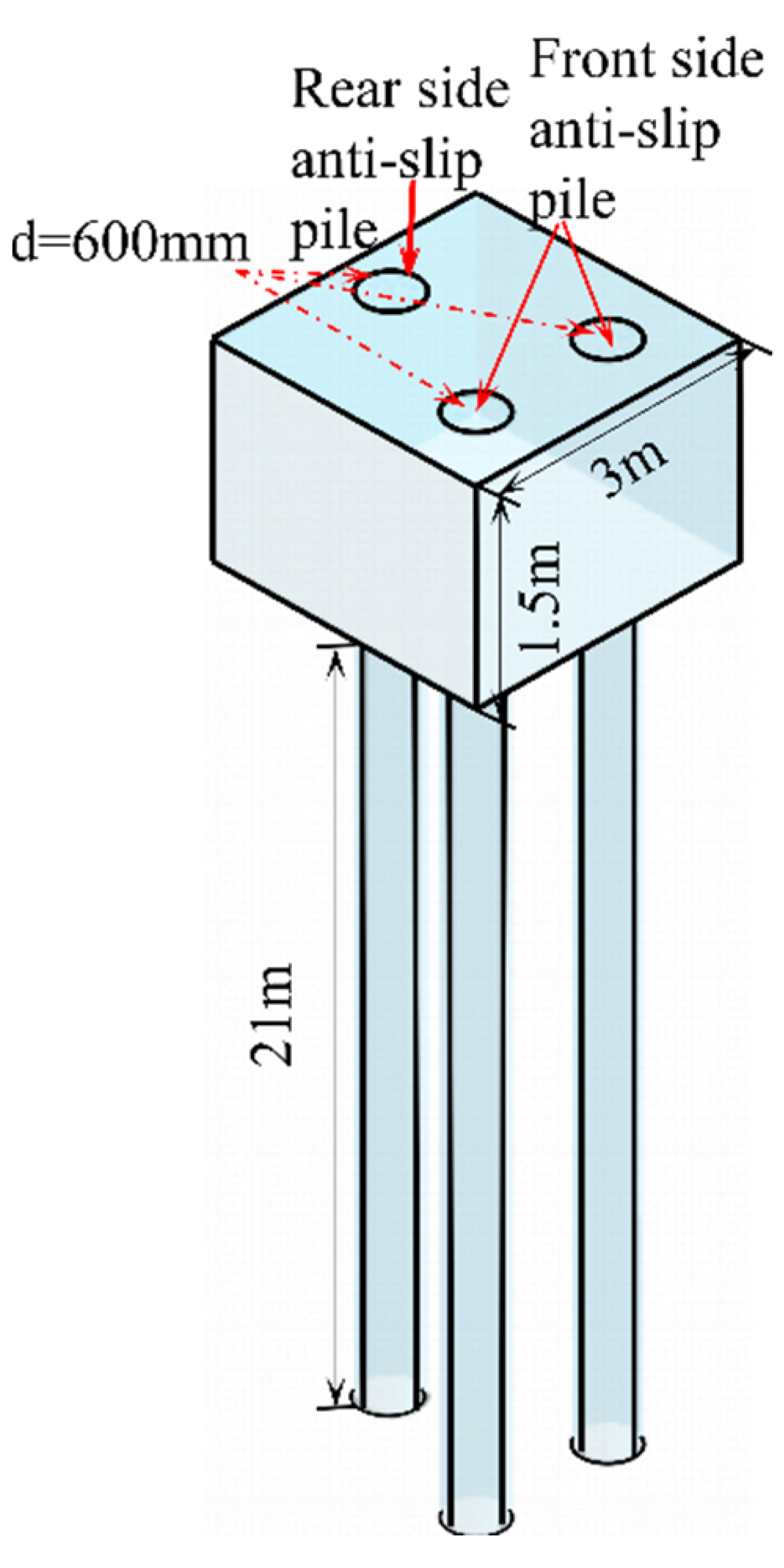
To existing tunnels suffering from landslide damage, we usually apply anti-slide piles, anchors, and other support means. In this paper, the Nanping Tunnel of the DaTong-Zhungeer Railway is limited by terrain, so a combination of medium-diameter anti-slide piles (300 mm ≤ D ≤ 800 mm) is proposed as a support measure for the tunnel. Three circular piles of 600 mm diameter combined with medium-diameter anti-slide piles are distributed in a triangular shape, as shown in Figure 5.
In actual engineering design, the design of pile spacing has always been one of the complex problems, especially due to inconsistent soil arching effects between landslide thrust and soil resistance under different pile spacing conditions. Soil arching means that when the anti-slide piles are set to control the landslide body, the soil near the anti-slide piles tends to move out of the landslide body when it is subjected to the action of landslide thrust and soil resistance. The soil shear strength then forms the soil arching. As the soil arching is the result of the soil mobilizing its own strength to resist the external force, and considering that the compressive strength of the soil is greater than the shear strength and tensile strength, the arch axis of the soil arching is reasonable. Therefore, a reasonable pile spacing in the design will form an effective soil arching thus achieving resistance to landslide thrusts. Li, C D et al. (2010) [29] divide soil arching into three levels that can be improved in combination with engineering practice. The interaction of anti-slide pile and soil with the increasing pile spacing is divided into four stages: ① Post-pile soil arching stage (Figure 6a): When the distance between the piles is small, the soil behind the pile is subject to a small landslide thrust, and the angle α between the hypotenuse of the triangular pressure zone behind the pile and the line connecting the pile midpoint is smaller. The pile spacing determined by the calculation is the minimum pile spacing. ② Pile corner soil arching stage (Figure 6b): As the pile spacing increases, the soil behind the pile is gradually increased by the landslide thrust, part of the arch foot soil acts between the piles, and the soil forms a pile corner soil arching to transfer the load to the back wall and side wall of the anti-slide pile. ③ Soil arch between piles stage (Figure 6c): The distance between the anti-slide pile continues to increase, and the triangular compression zone behind the piles disappears, forming soil arches between the piles. At this time, the landslide is thrust mainly by the soil arch and anti-slide pile friction balance; the calculated pile spacing at this time is the maximum pile spacing. ④ Soil arching failure stage: At this time, the pile spacing is large, resulting in the inability to form an effective earth arch between the piles, and the anti-slide piles mainly bear the landslide thrust.
To avoid the complexity of 3D landslides, most engineers perform a 2D simplified mechanical analysis of landslides based on uniformly distributed driving forces without considering the influence of 3D characteristics on the distribution of driving forces. In fact, for a large number of avalanche landslides in China, the thickest location of the slide is usually found in the middle of the slide, and the thickness of the slide decreases gradually with the distance from the center to the side boundary [25,29,30]. Therefore, the conventional planar arrangement of anti-slide piles under the effect of a uniform driving force may cause a huge waste of investment. Therefore, a new simplified model is proposed for characterizing the 3D sliding mass of the avalanche slope. For quantitative derivation, a semi-flat ellipsoidal model is used to describe the spatial dimensions of the sliding mass of the landslide (Figure 7). In this model, V is the maximum depth of the sliding mass, Q is the maximum horizontal distance from the pile to the top of the pile, d is the width of the landslide along the pile row cross-section, J is the longitudinal profile with x distance from the main slip profile, 2n is the depth of the sliding mass on cross-section J, and m is the distance along the oy axis in section J.
As can be seen in Figure 8, when the soil arching effect enters the third stage of the soil arch between piles, relying on the friction between piles and soil as the main soil arch resistance, the pile spacing designed at this time is the maximum pile spacing. When determining the pile spacing of the combined medium-diameter anti-slide pile used in this paper, the following assumptions are made for the convenience of calculation:
As the spacing between the three piles of the combined pile and the main slip surface size is relatively small, the pile bodies are subject to greater landslide extrusion, and the soil and pile enclosed by the pile and pile can be approximated as an anti-slide whole. That is, it forms a triangular prism-shaped pile body.
In this paper, a tunnel lining structure is in front of the combined piles so that the corresponding passive earth pressure will be provided. Due to the arc shape of the tunnel, this part is regarded as a rectangular retaining wall to facilitate the calculation of passive earth pressure.
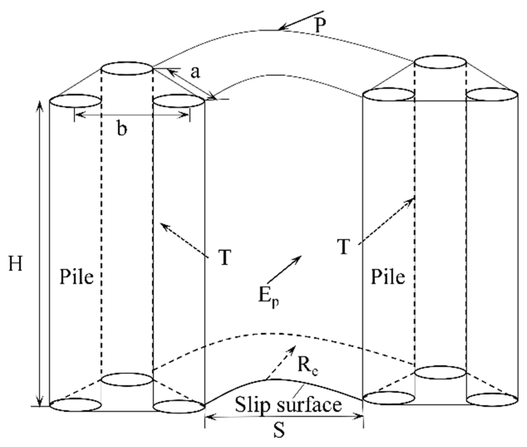
A reasonable range of pile spacing is obtained using the frictional soil arching effect [29,31]. The maximum pile spacing is determined using the calculation model shown in Figure 8 considering the soil arch effect. According to the force balance, the maximum frictional force T of the pile is determined as the following Equation (1) [31]:
T = 1 2 ( P E P R e )
where P is the total landslide driving force between the combined piles; Re is the resistance of the soil arch between the piles; and E p is the passive earth pressure of the sliding body in front of the combined piles.
The passive earth pressure of clayey soil is found with Equation (2):
E P = 1 2 K P γ H s 2 + 2 c H s K p
where K P is the Rankine passive earth pressure coefficient and H s is the height of the tunnel lining structure located above the slip surface, taken as 8.2 m.
Wang et al. (2001) [31] also assumed that the landslide driving force is completely transferred to the anti-slide pile through the frictional soil arching; therefore, the normal stress N s can be calculated as the following Equation (3):
N s f = 1 2 q · s
where q is the strength of the landslide driving force, which can be calculated as q = P / S .
Using the Mohr–Coulomb criterion, the maximum friction ( ) of the pile can also be expressed as in Equation (4):
T = N s · t a n φ + c · a · H = 1 2 q · S · t a n φ + c · a · H
where c and φ are the cohesion and friction angle of the sliding body near the pile.
As for the resistance of the sliding body between the stabilized piles, it can be determined by the Mohr–Coulomb criterion along the sliding surface [29]:
R e = γ · S · H · ( c o s θ · t a n φ s i n θ ) + c · a · H
where γ is the unit weight of the sliding mass (kN/m3), θ is the stabilization pile position at the sliding surface of this paper, taken 10°, as shown in Figure 8, for the combination of pile before and after the pile spacing; a = 3, d = 3 × 0.6 m = 1.8 m.
Equations (1)–(5) combined can be obtained in the soil arch phase between piles, and the maximum net pile spacing S is given by the following Equation (6):
S = c · a · ( 2 H + 1 ) + 1 2 K p γ H s 2 + 2 c H s K p q · ( 1 t a n φ ) γ · H · ( c o s θ · t a n φ s i n θ )
The landslides in this paper are mainly composed of clay, so the maximum landslide thrust is calculated according to Equation (7) proposed by Dai et al. (2002):
q ( z ) = ( 36 k 24 ) E h 1 3 z 2 + ( 18 24 k ) E h 1 2 z
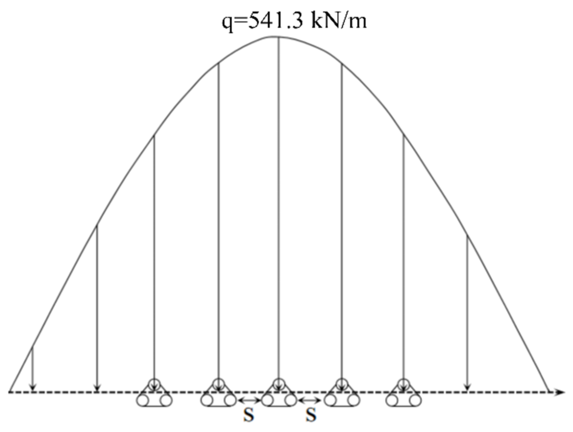
Table 1 lists the physical and mechanical parameters involved in calculating the driving force. Determining the driving force by the residual thrust method is prescribed according to the national standard “Code for Geotechnical Investigation” (revised version in 2009). Therefore, as shown in Figure 9, the corresponding driving force strength of the stabilized pile design along the main sliding profile is q m a x = 541.3 kN/m. As shown in Figure 3, the sliding surface (θ) at the stabilized pile has a slope angle of about 10°. The calculation finally yields the net pile spacing S = 3.9 a = 11.7 d, so this paper takes 12.5 d as this study’s maximum pile center spacing.
To study the mechanical characteristics of the combined medium-diameter piles and landslide and tunnel systems under different pile spacings, this paper further investigated the force characteristics at three different pile spacings (7.5 d, 10 d, and 12.5 d) using model tests combined with numerical simulation [27,28] for further study. The analysis of anti-slide pile body pile spacing is beneficial to actual project anti-slide support, while changing the pile spacing optimizes the economic benefits of the project in construction.

3.2. Model Materials

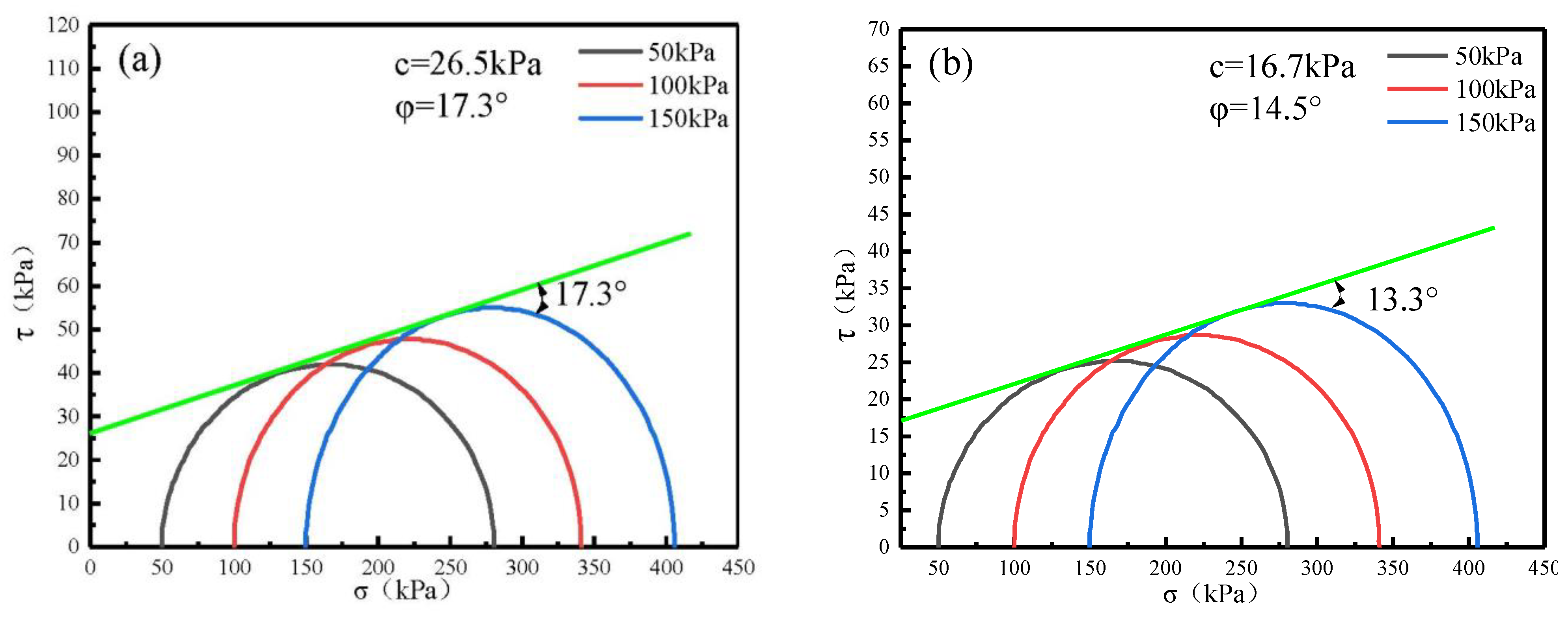
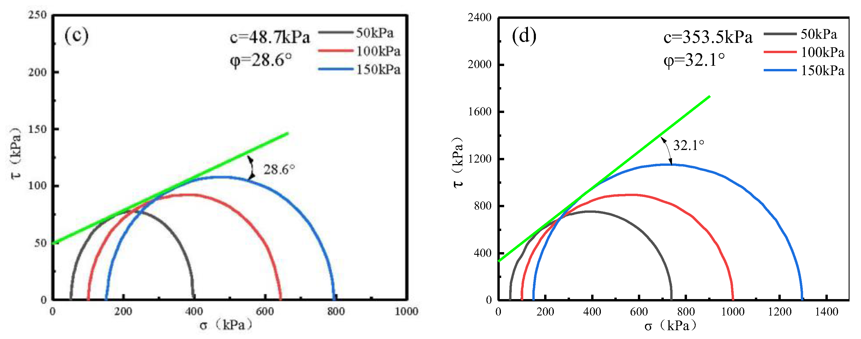
The landslide body in the model includes native clay from the southwest as its primary material, with a layer of filler every 5 cm to better replicate the experimental effect. According to the project’s working conditions, the sliding bed compaction is designed to be 96~98%, and the sliding mass compaction is designed to be 90~93%. The sliding mass was selected with the same moisture content of 18.2% as the actual project, and c = 26.5 kPa, φ = 17.3° measured by straight shear experimental, as shown in Figure 10a. The sliding zone is simulated by using a double layer of the plastic film filled with talcum powder, and the back calculation using the transfer coefficient method yields c = 18.8 kPa and φ = 13.5°, as shown in Figure 10b. The sliding bed used gravel, clay, and a small amount of the lime mixed and then heavy layered pressure to minimize settlement, measured by straight shear test c = 48.7 kPa, φ = 28.6 °, as shown in Figure 10c. The model is for anchoring the anti-slide pile to pick cement concrete to simulate the lower anchored bedrock, yielding c = 353.5 kPa and φ = 32.1°, as shown in Figure 10d. The specific model material parameters are shown in Table 2.

3.3. Experimental Similarity Ratio

The geometric similarity ratio is taken to be 1:30. The material capacity γ and cohesion c are proportioned according to similar materials. The tunnel lining, the elastic modulus E of the anti-slide pile, and Poisson’s ratio μ are configured according to certain proportions. According to the theory of similarity ratio, CL = 30, then Cγ = 1, Cμ = Cc = Cφ = 1, and Cσ = CE = 30, where L is the geometry, γ is the similar ratio of capacitance, μ, c, φ is the similar ratio of Poisson’s ratio, cohesion, internal friction angle; σ, E is the stress, elastic modulus.

3.4. Model Test Design and Production

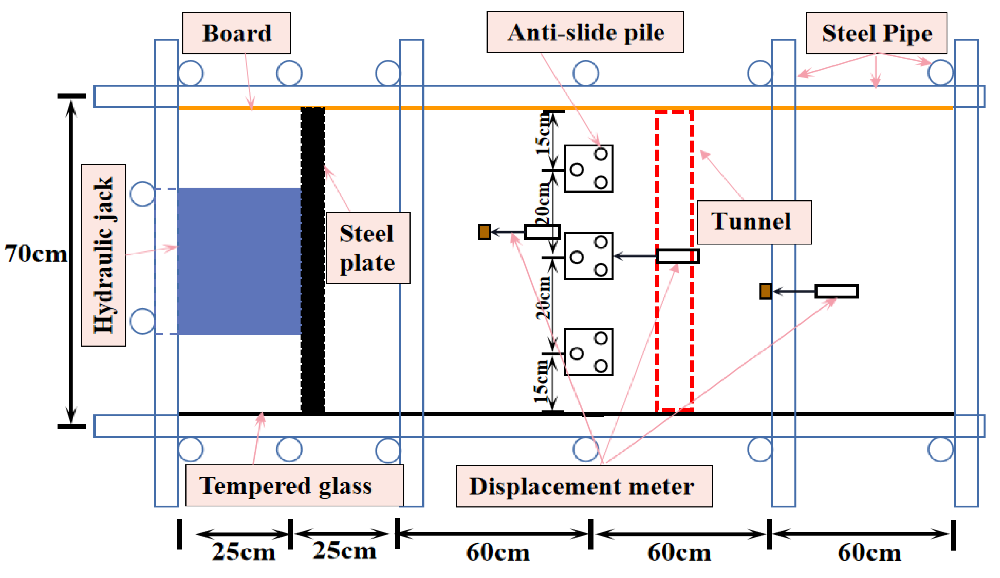
According to the same ratio, the experimental model of landslide is 230 cm long, 70 cm wide, and 120 cm high. The schematic diagram is presented in Figure 11, and the overall solid diagram of the physical model is displayed in Figure 12. The thickness of the sliding zone is 3 cm, the sliding zone material is composed of clay with a small amount of gypsum, and the slip body is composed of gravel powder grains compacted in layers so that its parameters meet the same ratio requirements. The slip bed was mixed with medium weathered gravel and a small amount of clay-lime and compacted to reduce unnecessary settlement deformation during the experiment. The bedrock was poured with concrete to simulate the strength of the bedrock in the lower part of the Nanping Tunnel to facilitate pile anchoring.
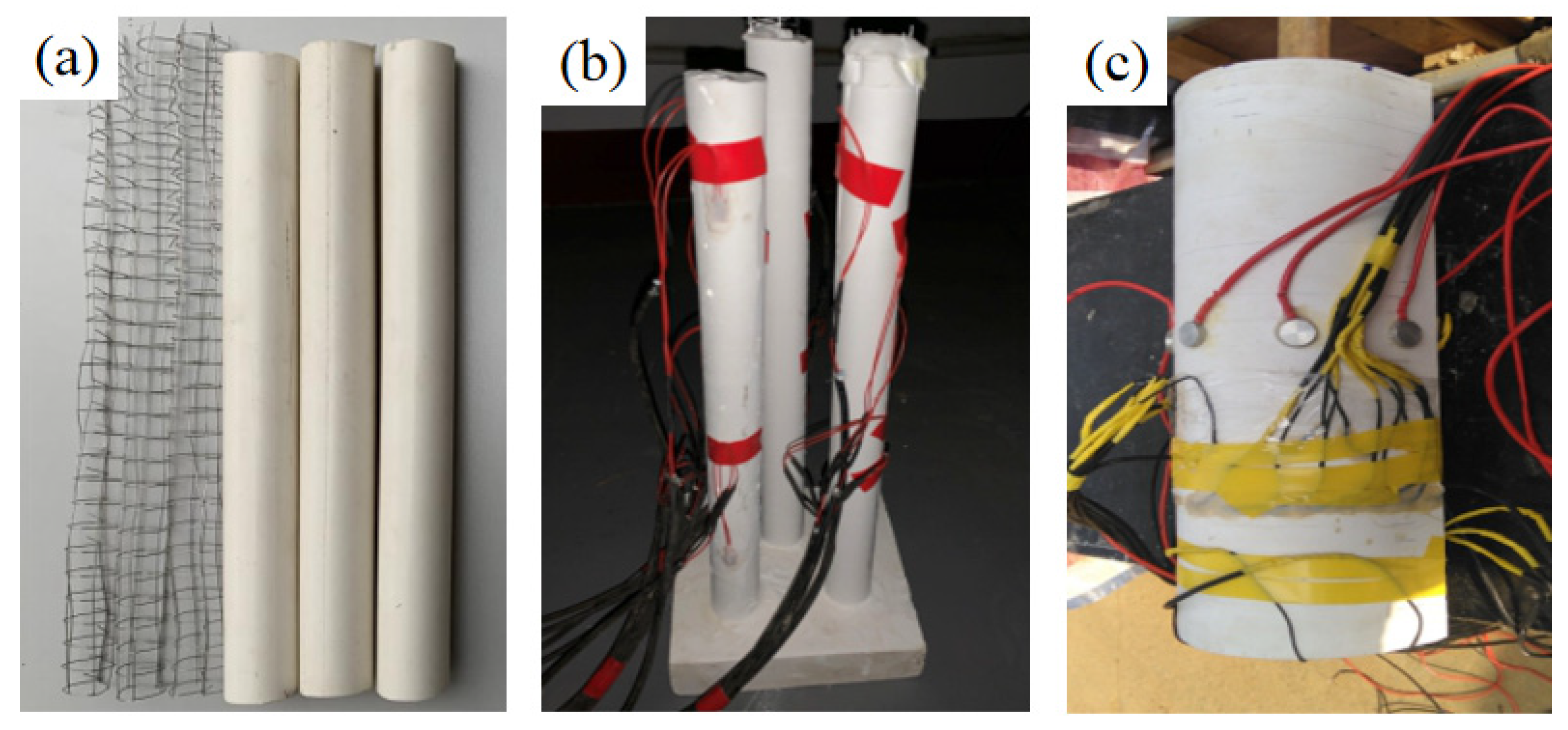
After the completion of the sliding bed laying, according to the engineering prototype location of equal proportions, the lower 17cm of the anti-silde pile is used as the anchorage section, and the tunnel is installed after the construction of the anti-slide pile is completed. The size of the anti-slide pile model is diameter d = 2 cm, the height of the cap is 5 cm, the cross-section is 10 cm × 10 cm square, and the tunnel model size is 30 cm high and 70 cm long. In the test, gypsum was used to simulate concrete with a ratio of gypsum:water = 2:1. A double layer of steel wire mesh was laid inside the tunnel to simulate a reinforcement cage with a wire mesh spacing of 12 mm and a diameter of 0.6 mm. The measured material parameters were γ = 22 kN/m3, E = 0.286 GPa, μ = 0.22. The model material of the tunnel lining can meet similar requirements, and the anti-slide pile and tunnel lining models are shown in Figure 13.
The adopted anti-slide piles were made according to the actual project at 1:30. There were 3 pile spacings, 15 cm, 20 cm, and 25 cm, that is, 7.5 d, 10 d, and 12.5 d, respectively, corresponding to the anti-slide pile layout form, as shown in Figure 14. It is also stipulated that in the medium-diameter combined anti-slide pile, the front pile is near the tunnel side, and the back pile is near the landslide body side.

3.5. Measurement Point Arrangement

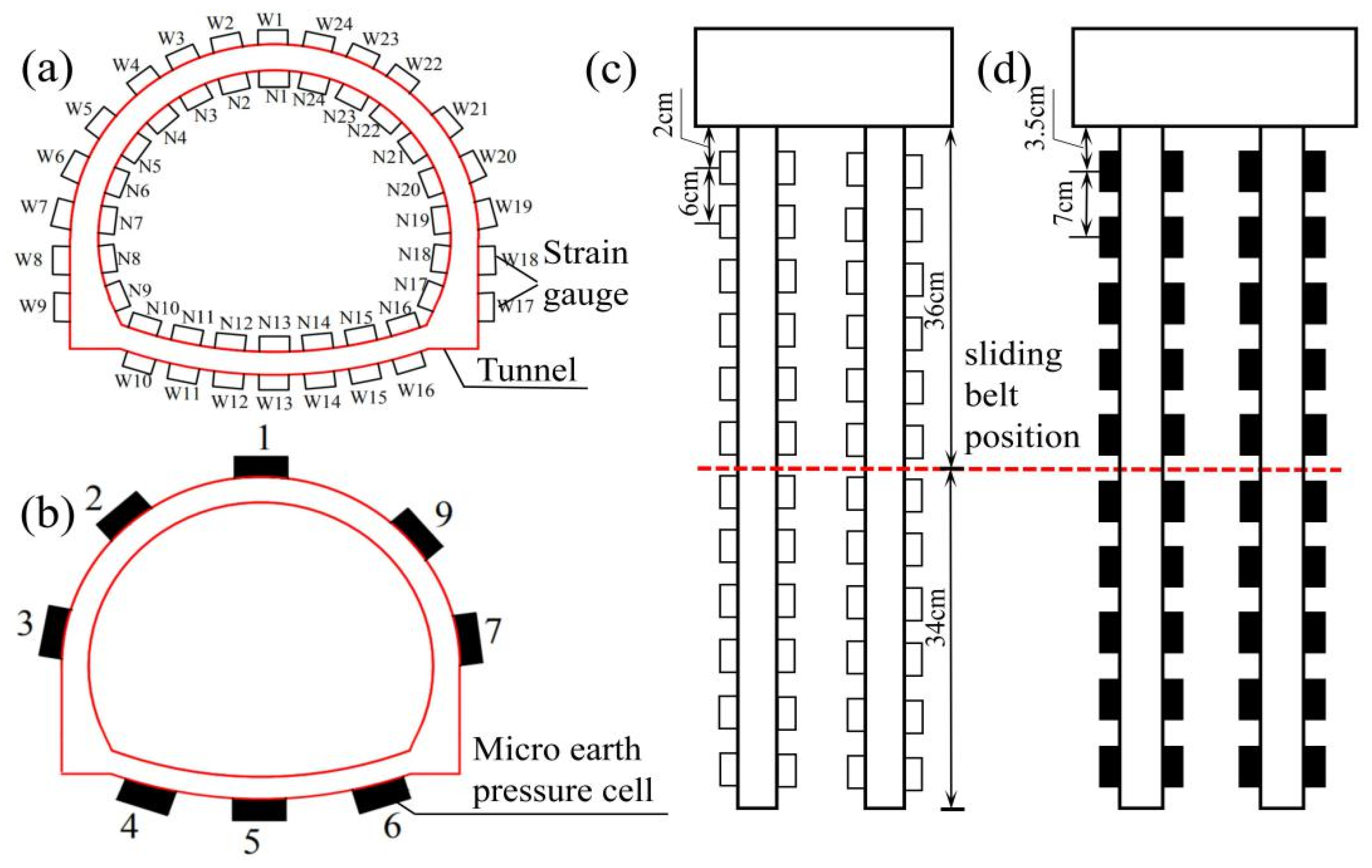
In order to study the effect of medium-diameter anti-slide piles on the tunnel lining support structure for three different combinations of pile spacing of 7.5 d, 10 d, and 12.5 d, strain gauges and micro-earth pressure boxes were arranged on the tunnel lining structure along with anti-slide piles as shown in Figure 15a–d. For each anti-slide pile, the measurement points were arranged with a spacing of 6 cm between each strain gauge and 7 cm between the micro-earth pressure cells.

3.6. Loading Scheme

The test uses a 1000 t hydraulic jack for loading. Between the sliding mass and the jack is placed a rectangular steel plate that can completely resist the sliding mass so that the concentrated load of the jack is transformed into a rectangular uniform load. The loading is carried out from the rear side of the slide body, and the specific loading arrangement is shown in Figure 16. Multi-stage loading is proposed for studying the interaction between landslide, pile, and tunnel under the three working conditions of 7.5 d, 10 d, and 12.5 d (15 cm, 20 cm, and 25 cm), and the displacement measuring devices are deployed in the upper sliding body and pile body. The detailed loading scheme is shown in Table 3. The test loading process is divided into three stages. The first stage load from 0 to 10 kN is divided into 2 steps, each loading 15 min, holding the load for 20 min, to ensure that the landslide model and the loading jack are fully fitted. The second stage load is increased from 10 kN to 25 kN and divided into 3 steps, each step is loaded for 20 min, and the load is held for 30 min. The third stage load is increased from 25 kN to 35 kN, each step is loaded for 30 min and held for 40 min, and when the load reaches 35 kN, the load is held until the slope fails. At this time, the sliding body part is significantly damaged, the pile body is also greatly deformed, and the sliding body shears and slides out from the top of the tunnel along the sliding zone.

4. Observation Analyses of Combined Pile Model Tests

4.1. Model Test Failure Characteristics

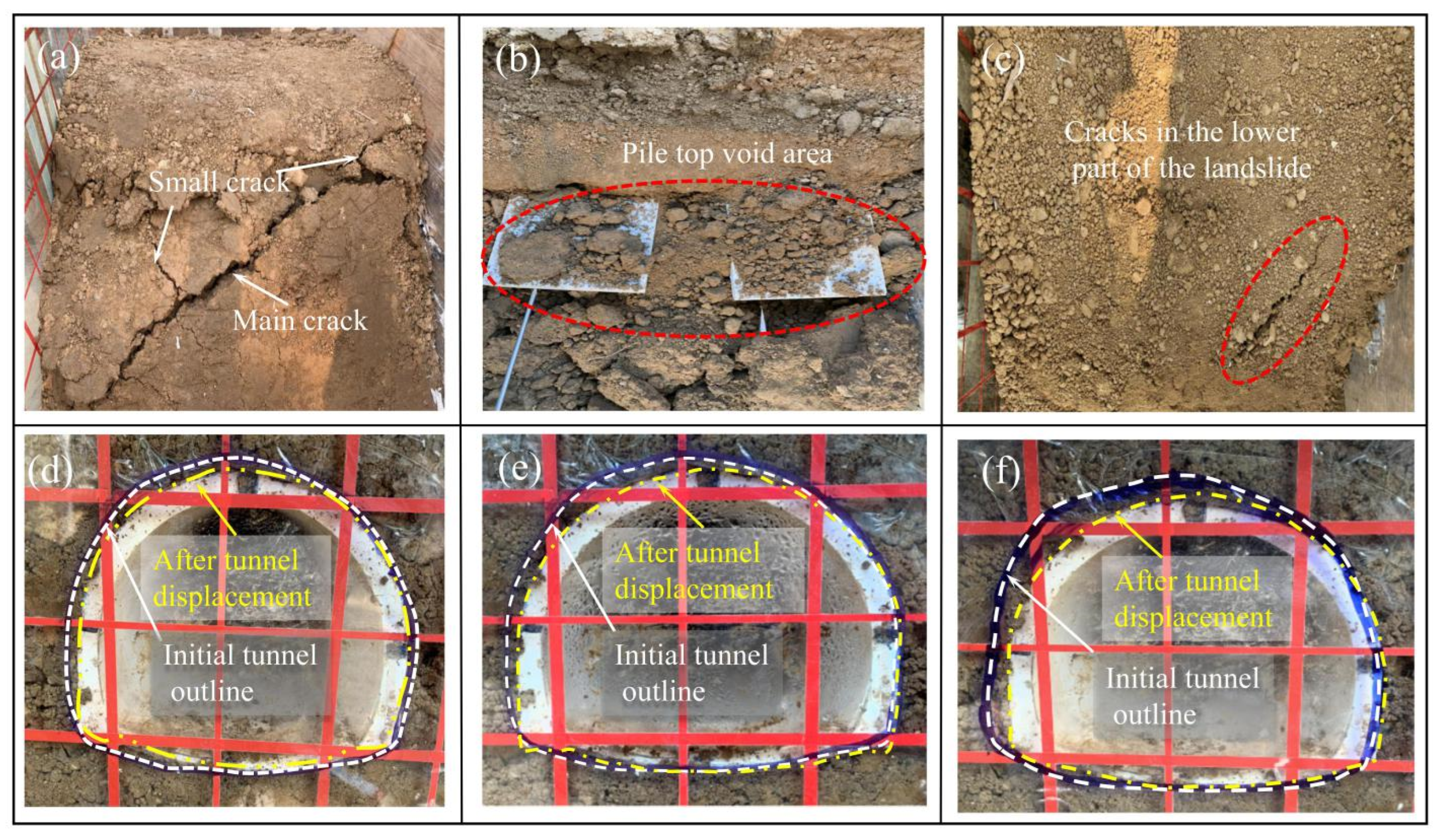
When the preload was applied (0~5 kN), the three groups of combined medium-diameter anti-slide piles with different pile spacings showed no apparent displacement, the top rear side of the pile was not separated from the slide, and the tunnel was basically not much deformed. The loads P applied for the first crack in the upper landslide at the three different pile spacings of 7.5 d (15 cm), 10 d (20 cm), and 12.5 d (25 cm) were 18 kN, 15 kN, and 12 kN, respectively. As the load continued to increase, the main crack produced by the upper landslide body also developed continuously, and the created landslide body about 3 cm wide had cracks when it was finally damaged, as shown in Figure 17a. At this time, the entire landslide model had failed. For the combined medium-diameter anti-slide piles with pile spacings of 10 d and 12.5 d, when the load P was 22 kN and 18 kN, the rear side of the pile top and the landslide mass begin to separate to form “a small void area” [1]. At this time, the tunnel also began to show tiny displacement. As the applied load gradually grew, the depth of the void area also increased, as shown in Figure 17b; the final void area widths of the combined medium-diameter anti-slide piles with pile spacings of 10 d and 12.5 d were 3 cm and 4.5 cm, respectively, and the depths were 8 cm and 9 cm, respectively, while the pile spacing of 7.5 d did not show an obvious void phenomenon. In summary, it can be seen that for three different combinations of medium-diameter pile spacing, transverse cracks and void areas of different sizes appeared between the pile and the upper sliding body. As the pile spacing increased, the crack size and the depth and width of the voids also increased.
With the increase in load, cracks of different depths appeared in the tunnel’s cover soil, and the crack’s depth and width gradually deepened with the increase in pile spacing. When the loading ended to the landslide model damage, at the pile spacings of 12.5 d (25 cm), 10 d (20 cm), and 7.5 d (15 cm), the tunnel out of the landslide body produced a significant slip, and the slide mass moved from the tunnel along the sliding zone. The top cut-out failure is shown in Figure 17d–f. At this time, the displacements generated by the tunnel under 3 different pile spacings are 5 mm, 3 mm, and 1 mm, respectively. At the same time, various cracks also appeared in the lower part of the landslide, as shown in Figure 17c.
In summary, three different pile spacing anti-slide piles only tilted forward near the slip surface without significant bending deformation. Still, the degree of tilting after the end of loading was different, from large to small, corresponding to the pile spacings of 12.5 d (25 cm), 10 d (20 cm), and 7.5 d (15 cm). This shows that the larger the pile spacing, the larger the landslide thrust assigned to each pile, and the greater the tilt of the anti-slide piles during loading.

4.2. Comparison Analysis of Displacement Distribution Law

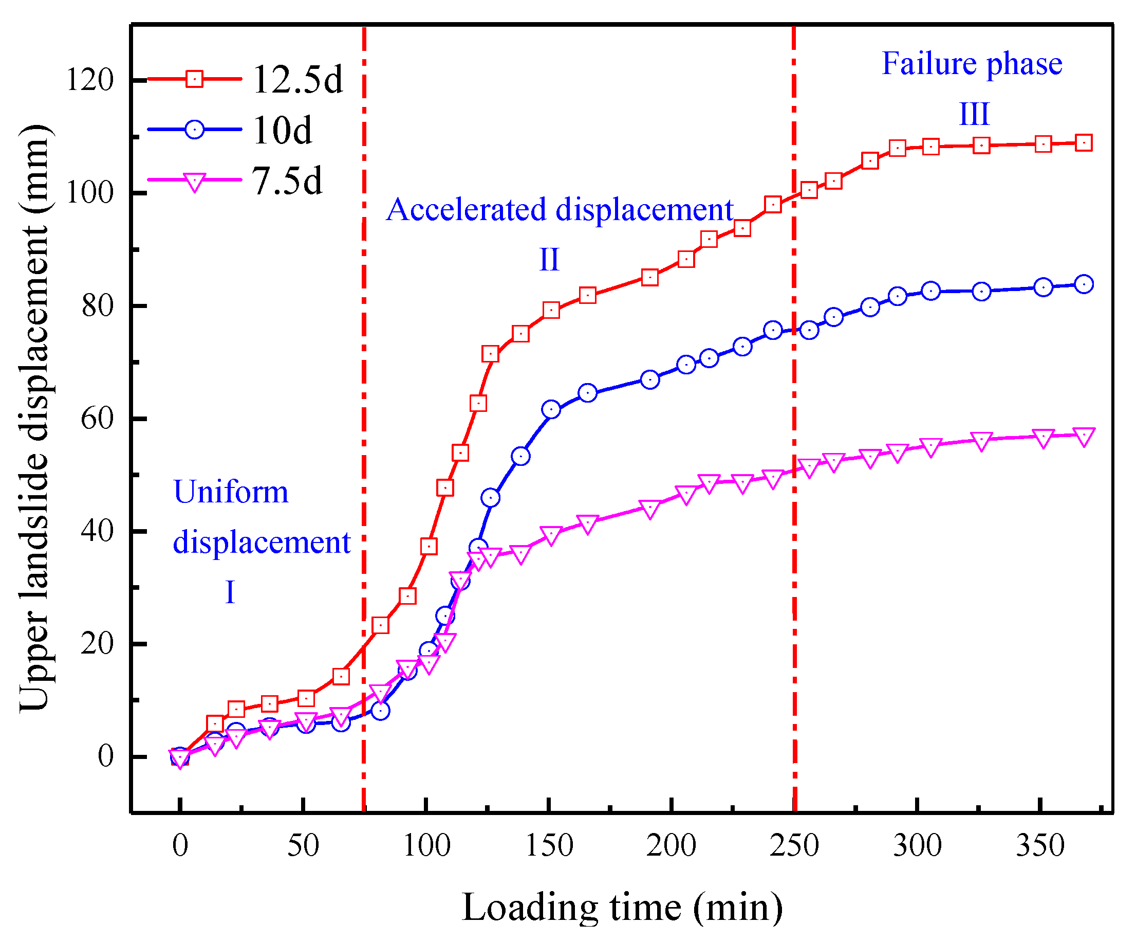
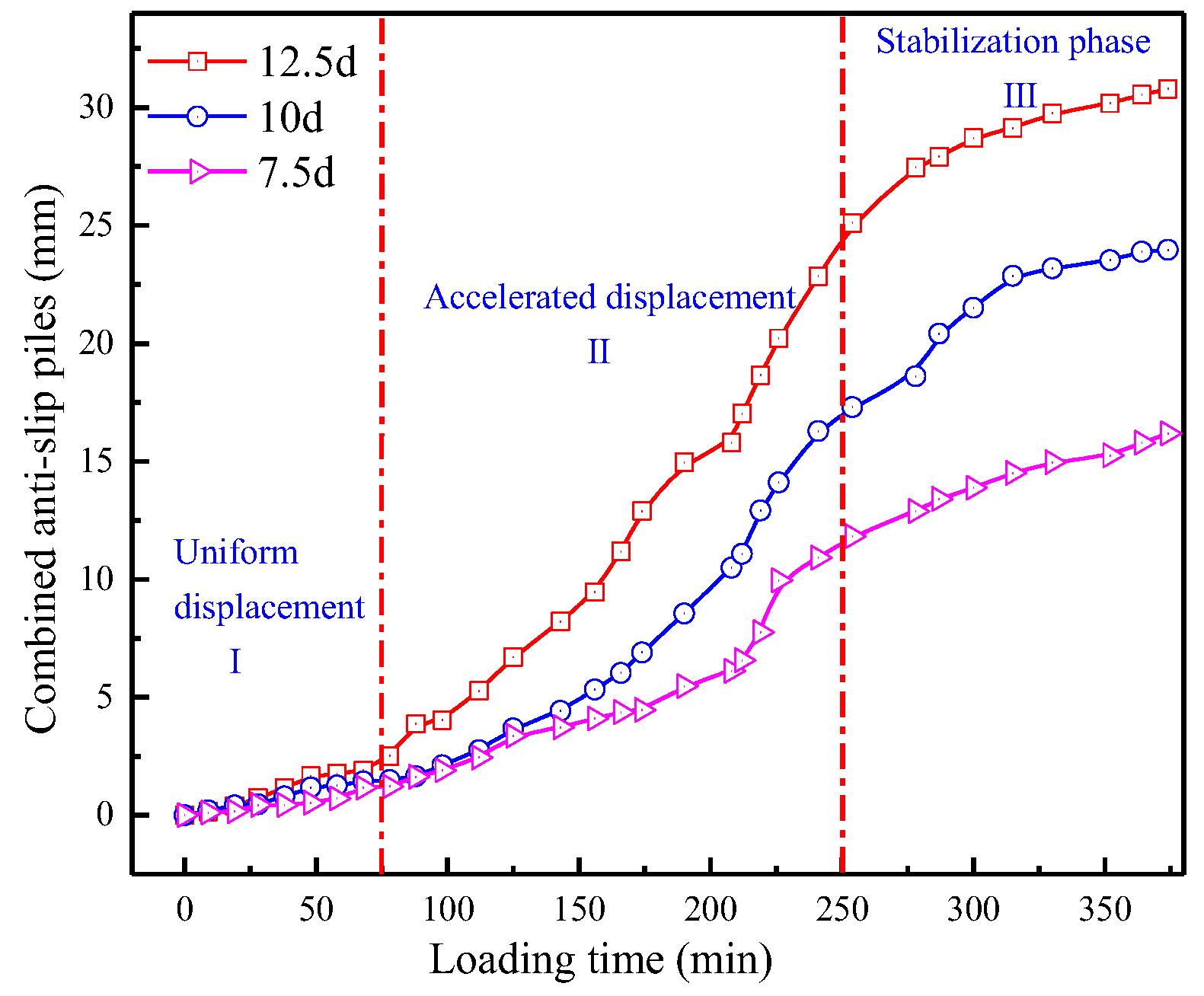
The curves of the horizontal displacement of the upper sliding body and the horizontal displacement of the pile top, with time under the action of three different combinations of pile spacing with medium-diameter anti-slide piles, are shown in Figure 18 and Figure 19.
(1)
The pile spacings corresponding to the horizontal displacement of the upper sliding body and the horizontal displacement of the top of the anti-slide pile from large to small in three different combinations of diameter pile spacing are 12.5 d (25 cm), 10 d (20 cm), and 7.5 d (15 cm) in order.
(2)
When the pile spacing increases from 7.5 d to 10 d, the horizontal displacement of the sliding mass and the horizontal displacement of the top of the anti-slide pile have significant gains in the net increase in horizontal displacement at the end of loading: 27.17 mm and 7.79 mm, respectively. The growth is 48.43% and 48.14%, respectively. When the anti-slide pile spacing is increased from 10 d to 12.5 d, the net increase in the horizontal displacement of the sliding mass and the horizontal displacement of the pile top are less, 31.2% and 28.5%, respectively.
(3)
According to the change in the displacement growth of the sliding mass with time during the loading process, the landslide damage evolution is divided into three stages: uniform displacement, accelerated displacement, and damage deformation. The pile top displacement also appears in the corresponding stage, as shown in Figure 18 and Figure 19. When the pile spacing is 7.5 d, the horizontal displacement of the landslide body and the horizontal displacement of the pile top grow more slowly with the increase in loading time. At the loading time of 0~75 min (corresponding to the load 0~10 kN), the horizontal displacement of the upper landslide body and the top of the pile under the action of three different pile spacing combination piles shows a uniform growth phenomenon. In 75~250 min (corresponding to the load of 15~30 kN), the growth rate of the landslide displacement increases more rapidly, and the slope body also appears to have deeper longitudinal cracks. After 250~350 min (corresponding to the load of 30~35 kN), the slope deformation rate is reduced and failure has appeared. This time, the pile displacement also appears in the stable stage, gradually reducing displacement. At the same time, the displacement and deformation of the tunnel present the same three deformation stages as those of the pile body (uniform displacement, accelerated displacement, and stable deformation). The tunnel displacement is 1 mm, 3 mm, and 5 mm under the action of three pile spacing at 7.5 d, 10 d, and 12.5 d (15 cm, 20 cm, and 25 cm), respectively. When the pile spacing increases from 7.5 d to 10 d increases the tunnel displacement by about 66.6%, and from 10 d to 12.5 d increases the tunnel displacement by about 40%.
(4)
The variation in the horizontal displacement of the pile top and the tunnel displacement under the three different pile spacing conditions are different, indicating that the effect of varying pile spacing on tunnel support is different. At the same time, the difference in tunnel protection is more prominent, which proves that different pile spacing for tunnel displacement deformation has a more significant impact. Therefore, it is of great significance to study the force characteristics of the tunnel and pile structure under the effects of different pile spacings for practical engineering.
In summary, when the pile spacing was increased from 7.5 d to 10 d, the effect of horizontal displacement of the pile top and tunnel displacement was much more significant than when the pile spacing was increased from 10 d to 12.5 d. This shows a much greater effect of increasing the pile spacing of combined piles from 7.5 d to 10 d to manage landslides to protect the tunnel was much greater than when the pile spacing was increased from 10 d to 12.5 d.

4.3. Earth Pressure Distribution

The values of earth pressure on the front and rear sides of the pile and tunnel lining structure measured in the test are obtained from the following Equation (8):
P = K ε
where K is the earth pressure box rate determination factor.
As can be seen from Figure 20, the three types of pile spacing have a common feature, the pile height at 36 cm (the top of the pile is set at 0 cm) has a sudden drop in the front and rear earth pressure, indicating that the center of rotation of the anti-slide pile is near here. The maximum force ratio of the front and rear piles (front pile force ratio on the rear pile force) is 0.883, 0.809, and 0.90 for the combined medium-diameter anti-slide pile under different pile spacings. This shows that the balance is close at 12.5 d (25 cm) and 7.5 d (15 cm) pile spacing, indicating that the front and rear piles can give full play to the anti-slide resistance under these two pile spacings. In comparison, at a pile spacing of 10 d (20 cm), the front and rear piles have a 20% difference in the force ratio, and the front pile cannot give full play to its anti-slide effect.
With the increase in pile spacing (from 7.5 d to 12.5 d), the combined medium diameter anti-slide pile’s rear pile soil pressure increased from 104.6 kPa to 242.6 kPa (an increase of about 131.9%), and the front pile increased from 116.1 kPa to 274.6 kPa (an increase of approximately 136.5%). The soil pressure on the left side of the tunnel arch increased from 54.1 kPa to 91.1 kPa (an increase of about 68.4%), and the force system consisting of anti-slide piles and the tunnel increased simultaneously. The sliding mass resistance in front of the pile in Figure 20 had an inverted parabolic distribution, which the following two reasons can explain: (1) The pile front slide is subject to more extruded loads due to the presence of the tunnel. (2) When the landslide body is a slip body with shear characteristics dominated by viscous cohesion, such as clay, when the anti-slide pile is in the elastic phase, the slip body resistance is basically an inverted trapezoidal distribution; after entering the elastic–plastic phase, the slip body resistance graph gradually changes to a parabolic shape with a non-zero surface (Dai et al. 2002).
As seen in Figure 20, the soil pressure on the tunnel lining structure also gradually increased with the increase in the anti-slide pile spacing. However, when the pile spacing is 10 d (20 cm), the front and rear piles of the anti-slide pile cannot give full play to its anti-slide effect, which is consistent with the experimental phenomenon that when the pile spacing increased from 7.5 d (15 cm) to 10 d (20 cm), the displacement of the sliding body caused by the increase of about 31.2% was greater than that of the pile spacing from 10 d (20 cm) to 12.5 d (25 cm). This shows that if the landslide thrust is significant in the actual construction process, the pile spacing should be reduced to 7.5 d or even smaller. If the landslide thrust is small, the pile spacing should be increased to 12.5 d or even more. Whether the landslide thrust is large or small, 10 d pile spacing support tunnel cost-effective.

4.4. Analysis of Pile and Tunnel Bending Moment Distribution Law

In the test, the strains of the piles were measured by pasting strain gauges in pairs before and after the anti-slide piles, and the tunnel bending moment was measured by pasting strain gauges inside and outside the tunnel in the same way. According to the bending theory in material mechanics, the tunnel bending moment can be obtained from Equation (9), and the anti-slide pile bending moment is obtained from Equation (10):
M = 1 32 π R 3 E ξ ( 1 r 4 R 4 )
where r is the tunnel liner inner diameter; R is the tunnel liner outer diameter; E is the tunnel liner modulus of elasticity; and ξ is the tunnel strain gauge value.
M = E I ( ε y + ε 1 ) d
where M is the bending moment of the section at the measurement point; E I is the bending stiffness of the pile; ϵ y , ϵ 1 are the compressive and tensile strains of the section at the measurement point, respectively; and d is the anti-slide pile diameter.
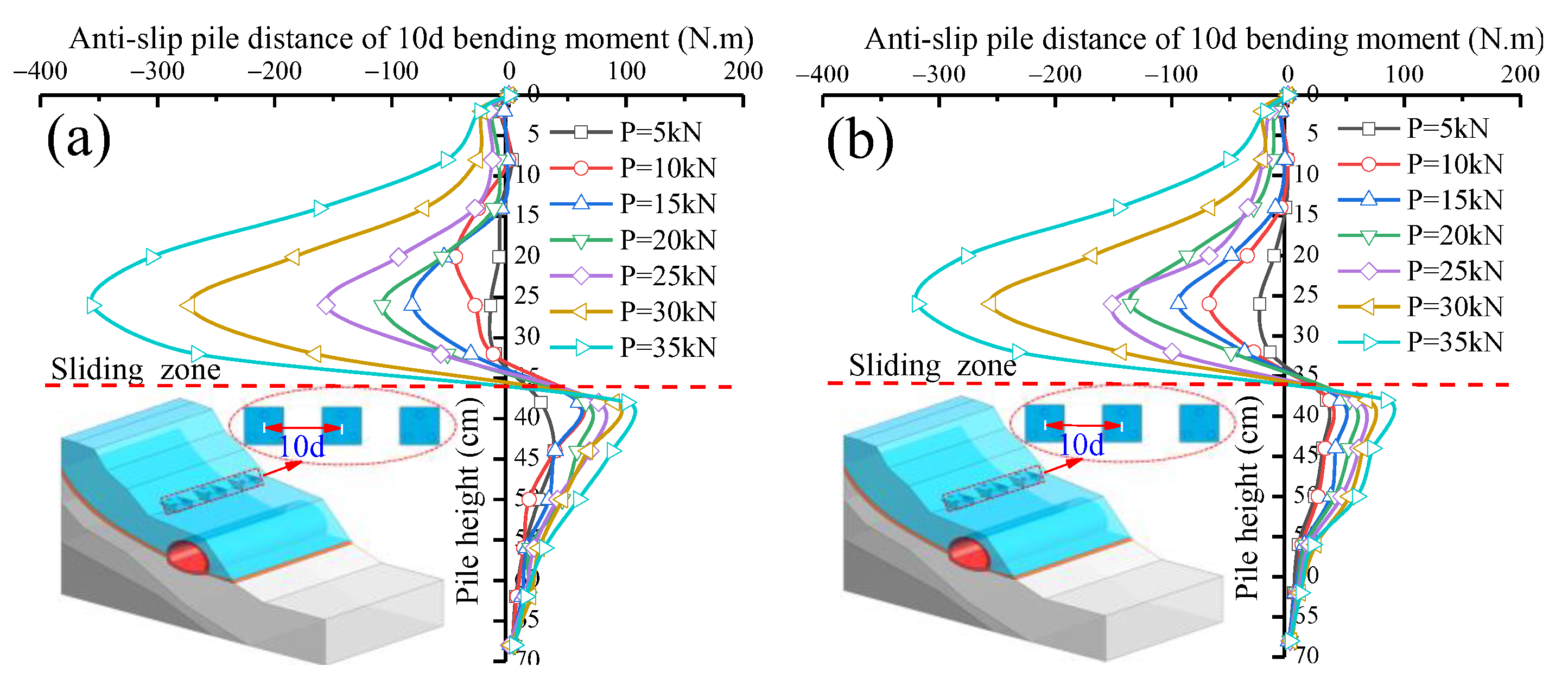
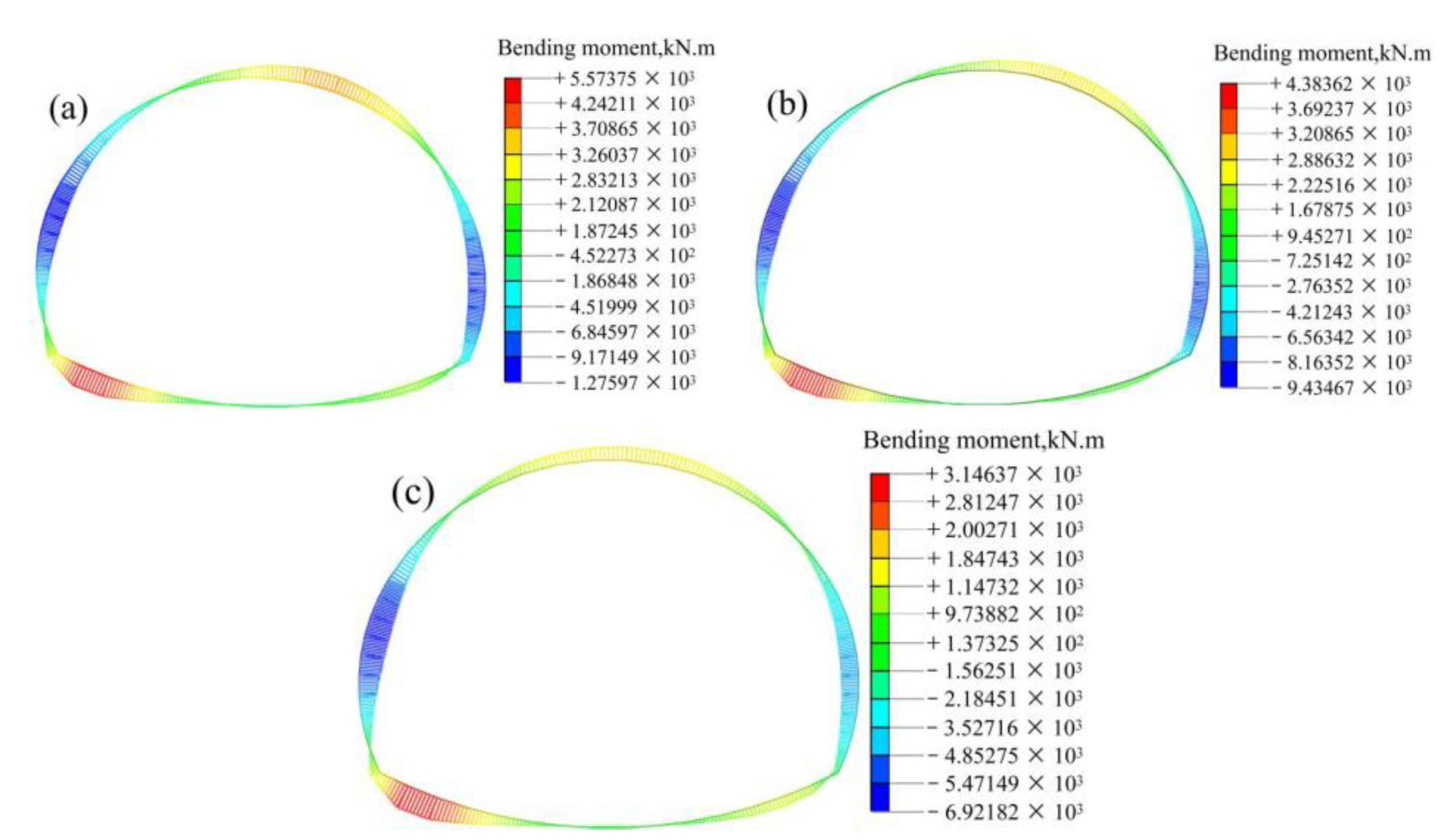
As shown in Figure 21, Figure 22, Figure 23 and Figure 24, the pile and tunnel bending moment distribution laws for three different pile spacings have the following similarities: ① Although the distance between the anti-slide pile is different, the bending moment distribution of the anti-slide pile is S-shaped, and the anti-slide pile body bending moment near the sliding surface position all tend to be close to 0. ② The bending moment of the tunnel shows an increasing trend with the increasing distance between the anti-slide piles, and the maximum tunnel bending moment occurs at the slip surface. A stressed system will be formed between tunnels and the same piles under different pile spacings, promoting the coordination of force and deformation between the two. ③ Anti-slide pile bending moments show a reverse distribution trend above and below the slip surface: above the slip surface, the anti-slide pile is under tension, and below the slip surface, the anti-slide pile is under pressure. ④ At the same time, the two arch sides of the tunnel are mainly subjected to compression bending under different pile spacings, and both are subjected to larger forces. The application of anti-slide piles mainly provides a support effect to the arch waist near the slip side of the tunnel, and the impacts on the arch foot and the arch roof are not too noticeable.
The difference between the three pile spacings is that: ① The maximum bending moments of the anti-slide piles and tunnels from large to small corresponded to pile spacings of 12.5 d (25 cm), 10 d (20 cm), and 7.5 d (15 cm); when the pile spacing increased from 7.5 d to 10 d, the increase in the anti-slide pile bending moment was about 56%, which was significantly larger than the 24% increase in the bending moment when the pile spacing increased from 10 d to 12.5 d. The tunnel bending moment increased by about 52.9% when the pile spacing was increased from 7.5 d to 10 d and by about 28.1% when it was increased from 10 d to 12.5 d. ② At pile spacings of 10 d and 12.5 d (20 cm and 25 cm), the pile bending moment increased approximately uniformly with a slight increase at P ≤ 10 kN; the pile bending moment increased sharply at 10 kN ≤ P ≤ 30 kN; and the pile bending increase returned to a flat rate at P ≥ 30 kN. The three phases of landslide deformation (uniform, accelerated, and damage) are consistent with those above three different forms, proving that the macroscopic external phenomena match perfectly with the experimental internal force changes. ③ There were also significant differences in tunnel lining support for different pile spacing conditions. At 12.5 d pile spacing, the tunnel bending moment value increased significantly, not only at the slip surface location but also extended to the whole tunnel near the slip side, and the tunnel was about to experience damage. ④ When the pile is loaded by P≥30kN, the slip surface at the moment of a large turn, the moment above the slip surface appeared to increase sharply. With P < 30 kN loading, the slip surface slowly increased the moment above and below. It was proved that the landslide as damaged, and the gradual decrease in the bending moment above the pile top was in line with the aforementioned “deglaciation phenomenon” above the pile top. Moreover, the difference between the 10 d and 12.5 d slip surface bending moments at P ≥ 30 k N is more significant than that at 10 d pile spacing.
In summary, when the pile spacing increased from 7.5 d to 10 d, the anti-slide pile tunnel support effect was much more significant than when the pile spacing increased from 10 d to 12.5 d. This shows that when the pile spacing increases from 7.5 d to 10 d, the attenuation effect on the tunnel support effect is more apparent. The selection of pile spacing should be carefully studied in the project’s construction.

5. Numerical Simulation Analyses of Pile Strengthening Model Tests

5.1. Numerical Modeling

According to the prototype structure of the Nanping Tunnel of Da-Zhun Railway, based on the actual engineering survey and design data, a partial landslide model with a length of 70 m in the X direction and 36 m in the Y direction, a tunnel length of 20 m, a tunnel diameter of 10 m, a lining thickness of 0.5 m, a pile length of 21 m, a single pile diameter of 0.6 m, an upper bearing platform height of 1.5 m, and a bearing platform cross-section size of 3 m × 3 m was established for simplified calculation. Models were established under the three different pile spacings of 7.5 d, 10 d, and 12.5 d, as shown in Figure 25.
The overall model consists of a sliding mass body, sliding zone, sliding bed, bedrock, tunnel, and pile body. At the same time, steel reinforcement elements are implanted in the anti-slide pile and the tunnel, using different colors to distinguish different material properties. The model parameters used in the numerical simulation are shown in Table 4. The similarity ratio converts the model parameters of numerical simulation. Divide the sliding mass according to the grid size of 0.8 m. The slide zone is divided according to the 0.5 m grid size. The slip bed and bedrock are divided according to the grid size of 2 m. The anti-slide pile and tunnel grid size are divided according to 0.5 m. In order to ensure the accuracy of the simulation, the xy plane, yz plane, and y = 0 plane are fixed constraints. The bottom of the piles and tunnel units are rotated, fixed, and restrained, and the initial earth stress is set to be the self-weight stress field. The direction of gravity is set to the negative direction of the Z-axis. In the calculation, the initial earth stress is first balanced, and then the displacements of all nodes are set to zero to ensure that the calculation is based on the initial earth stress balance. The model test load is translated into the actual working condition load using a similar ratio, and the load position is the same as the model test.
The contact units between pile and soil, tunnel structure, and soil are set in the simulation. The material parameters include pile contact unit last shear 0.99 N/m, normal stiffness coefficient 0.99 kN, pile-soil and tunnel contact unit principal stress stiffness modulus 2.45 MPa, and shear stiffness modulus 0.245 MPa.

5.2. Analysis of Numerical Simulation Results

5.2.1. Displacement and Deformation Analysis

As can be seen from Figure 26a, when there is no support to the landslide, the tunnel near the slope side will have a large deformation, a maximum of about 63.4 cm, which already seriously affects the use of the tunnel. Therefore, the existing tunnel must be supported to prevent further landslide development. As can be seen from Figure 26b, when a combination of medium-diameter anti-slide piles with a pile spacing of 12.5 d (7.5 m) is applied as a support, the maximum deformation of the pile–tunnel variety is about 8.5 cm, and it is concentrated in the smaller area at the top of the tunnel; the overall deformation of the pile–tunnel combination tends to be 3.7 cm. The deformation is reduced by about 88% compared with that when no anti-slide piles are applied as support. As can be seen from Figure 26c, when the anti-slide pile spacing is 10 d (6 m), the deformation at the top of the tunnel is about 6.7 cm, and the average displacement of the pile–tunnel combination is about 2.3 cm, which is 37.8% less than the deformation of the pile spacing of 12.5 d, similar to the 31.2% chance of the pile top displacement when the pile spacing increased from 10 d to 12.5 d in the previous test. As can be seen from Figure 26d, when the pile spacing is 7.5 d (4.5 m), the maximum displacement occurs at the top of the anti-slide pile of about 3 cm, at which time the average displacement of the pile–tunnel combination is about 1.3 cm, and the tunnel as a whole remains stable. Compared with the 10 d pile spacing, the displacement decreases by about 43.5%, closer to the displacement increase of approximately 48.43% when the displacement test data increased from 7.5 d to 10 d in the previous paper.
The maximum deformation occurs at the top of the anti-slide piles on the mountainside of the tunnel. At the same time, the deformation of the tunnel lining structure gradually decreases as the distance between the anti-slide pile’s decreases, which is consistent with the displacement law derived from the model test, only slightly different in the deformation value. Furthermore, the change range of displacement from 7.5 d to 10 d is greater than the average change range of displacement from 10 d to 12.5 d, which is consistent with the conclusion from the previous test. In the most unfavorable position of the tunnel lining structure, the anti-slide pile protection basically will not produce large displacement deformation. After applying an anti-slide pile tunnel, maximum deformation generally appears at the top of the tunnel, and the value is small.

5.2.2. Stress of Tunnel in Surrounding Rock

Figure 27 shows the tunnel stress distribution under the support without an anti-slide pile and applying different pile spacing combined medium-diameter anti-slide pile. From Figure 27a, it can be seen that significant stress distributions occur on the inside and outside of the tunnel without anti-slide pile support, mainly at the intersection with the sliding zone and close to the side of the mountain, and the maximum stress occurs at the inside of the tunnel about 0.61 MPa. As can be seen from Figure 27b, the stress in the surrounding rock of the tunnel under the action of the anti-slide piles with a pile spacing of 12.5 d was applied, and the maximum stress at this time still appeared in the inner side of the tunnel where it intersected with the sliding zone, about 0.19 MPa. This indicated that after the anti-slide piles were applied, the thrust of the landslide body was effectively suppressed, and the surrounding rock stress of the tunnel showed a significant decrease. Figure 27c,d show the surrounding rock stress of the tunnel at a pile spacing of 10 d and 7.5 d, respectively. It can be seen that the maximum stress position of the tunnel occurs at the location where the sliding zone intersects the tunnel, and the stress in the inner side of the tunnel decreases as the pile spacing decreases. When the pile spacing is 10 d, the maximum stress inside the tunnel is about 0.0869 MPa; when the pile spacing is 7.5 d, the maximum stress inside the tunnel is reduced to 0.0234 MPa.
In summary, when anti-slide piles are applied, the tunnel stress decreases significantly, which proves that the anti-slide piles can effectively support the landslide thrust and protect the tunnel lining structure. At the same time, it can be seen that when anti-slide piles with different pile spacings are applied, the change in tunnel stress when the pile spacing is increased from 7.5 d to 10 d is greater than that when the pile spacing increases from 10 d to 12.5 d, which is consistent with the previous experimental study and the trend of displacement change.
In the actual construction process, if the landslide thrust mainly results in large tunnel stress, the pile spacing should be reduced appropriately to 7.5 d or even smaller. If the landslide thrust is small, the pile spacing can be increased to 12.5 d or even significantly more. Whether the landslide thrust is large or small, the cost-effectiveness of supporting tunnels with a pile spacing of 10 d is relatively low.
Figure 28a,b show the major and minor principal stresses in the surrounding rock of the tunnel under different pile spacings, respectively. When the anti-slide piles are applied near the tunnel side landslide, it can be seen from Figure 28a,b that the stress in the tunnel surrounding rock gradually decreases, and both the major and minor principal stresses gradually decrease as the pile spacing decreases. From Figure 28a, when the anti-slide piles are not applied, the maximum major principal stress in the surrounding rock around the tunnel appears on the side near the landslide body, which is about 0.75 MPa. At the same time, the tunnel stress distribution is consistent with the above. All show the phenomenon of higher surrounding rock stress at the sliding zone. At the same time, the principal stress of the tunnel surrounding rock is reduced after applying anti-slide piles, and the support effect for the surrounding rock varies under different pile spacing working conditions (because in soft ground boundary and strongly weathered shale, the major principal stress is tensile, while the minor principal stress is compressive [19]; Under different pile spacings, the support effects for the tunnel surrounding rock are also different, and the major and minor principal stresses in the surrounding rock show a simultaneous decrease with decreases in pile spacing.
The major principal stress in the surrounding rock is reduced by about 75% at the maximum value when the pile spacing is 7.5 d, 60% at 10 d, and 47.5% at 12.5 d. This shows that the smaller the anti-slide pile spacing, the greater the reduction in the principal stress in the tunnel in weak ground. Because the surrounding rock is in tension at the boundary between the weak stratum and the strongly weathered shale, it is necessary to construct anti-slide piles on the slip side under similar conditions for safety reasons. Considering that some of the tunnel elevation arches may be in tension, it is recommended to install radial anchor cable support and grouting support at the elevation arch position under similar conditions.

5.2.3. Bending Moment Analysis

Figure 29 and Figure 30 show the magnitudes of the bending moments on the tunnel lining structure and pile at different pile spacings from the numerical simulation. The maximum bending moment of the rear pile and the front pile of the combined pile are both located above the slip surface, and the reverse bending point is located at the slip surface; the overall bending moment shows an S-shaped distribution consistent with the law obtained from the model test. The maximum bending moment of the tunnel is distributed at the arch foot on the side of the mountain, and the overall bending continues to show negative bending moment values for the side arches under pressure on both sides of the tunnel, and positive bending moments for the inverted arch and the arch foot are in tension. When the anti-slide pile spacing is 12.5 d (7.5 m), the maximum bending moments of the pile body and the tunnel are 20,439.4kN·m and 1270.2 kN·m, respectively. When the anti-slide pile spacing is 10 d (6 m), the combined piles’ maximum bending moments of the pile body and the tunnel are 17,319.4 kN·m and 940.3 kN·m, respectively. When the anti-slide pile spacing is 7.5 d (4.5 m), the pile body’s maximum bending moment and the tunnels are 12,600.3 kN·m and 690.1 kN·m. Consistent with the above model test law, the bending moment of the pile and tunnel lining stressed structure gradually decreases as the pile spacing increases.
In summary, numerical simulations were used to analyze the deformation of pile and tunnel lining structures under different pile spacings. When the pile spacing gradually increased (from 7.5 d to 12.5 d), the overall forces and deformation of the tunnel and pile body gradually increased. The role of different pile spacings for tunnel lining protection has a large gap: When the pile spacing increased from 7.5 d to 10 d, the pile body force increased by 37.3%, the tunnel lining force increased by 36.5%, and the increase in the two was similar, whereas when the pile spacing increased from 10 d to 12.5 d, the pile force increased by 18.1%, and the tunnel lining force increased by 34.8%. At this time, there was a gap between the tunnel and pile increases, mainly because when the pile spacing increased, the landslide body thrust acted more on the tunnel lining structure, resulting in more force on the tunnel.
In the process of numerical simulation, the trend of force analysis under the action of different pile spacings is consistent with the earlier test results: When the pile spacing increased from 7.5 d to 10 d, the influence of the anti-slide pile tunnel support effect was much greater than when the pile spacing increased from 10 d to 12.5 d, and when the pile distance increases from 7.5d to 10d, the effect of piles on tunnel support attenuation is more obvious. The conclusions are consistent.
Therefore, numerical simulations were used to analyze the force and deformation of the tunnel lining structure under different spacings of the combined anti-slide piles. When the anti-slide pile spacing increased gradually (from 7.5 d to 12.5 d), the overall force and deformation of the tunnel and pile body also steadily increased. The different pile spacings for the tunnel lining protection were significantly different; in the numerical simulation and model test, we can conclude that 10 d pile spacing is the lowest cost-effective choice.

6. Discussion

6.1. Contrast Analysis

Tian, X. (2021) [17] analyzed the deformation characteristics of the lining and the damage pattern of the slope by monitoring the entire construction process of the Xiamaixi Tunnel and evaluated the effectiveness of the reinforcement measures. Through on-site monitoring, it was found that the overall earth pressure and bending moment distribution of the tunnel lining were consistent with the trend in this paper. The earth pressure distribution was nonlinear along the liner periphery, with a significant downward trend after passing through the support. In this paper, the intersection of the Nanping Tunnel and landslide mainly occurred at the left arch waist near the foot of the arch, while the Xiamaixi Tunnel and landslide mainly intersect near the top of the arch. Therefore, the phenomenon that the left side of the arch waist bending moment of Nanping Tunnel has a broader range of negative values and the right side of the arch top bending moment is more minor appears in this paper.
Moreover, Xiaoxu Tian et al. used internal tunnel strengthening and slope excavation to support the tunnel lining in their paper, but the bending moment and earth pressure on the tunnel lining was still reduced by about 16%. In this paper, after using combined medium diameter anti-slide piles, the maximum pile spacing of 12.5 d tunnel lining structure and overall stress reduction of about 47.5% can be seen as the advantages of this method. It is shown that although the relationship between the landslide and the tunnel location may lead to differences in the specific values of the tunnel forces, the overall tunnel lining force distribution trend is similar. At the same time, the use of combined medium-diameter anti-slide pile support has more advantages than the traditional support method.
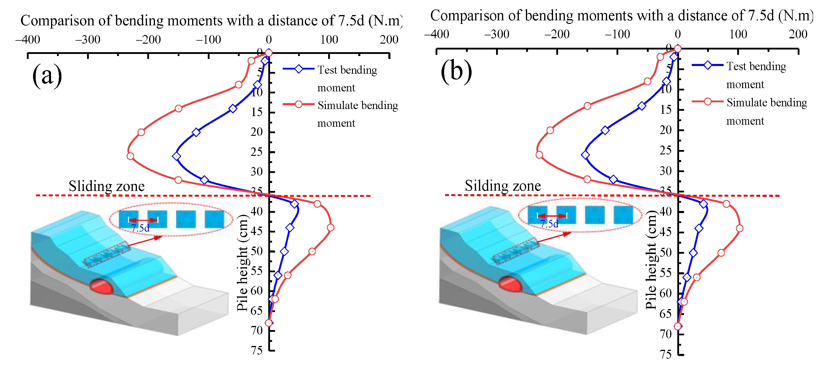
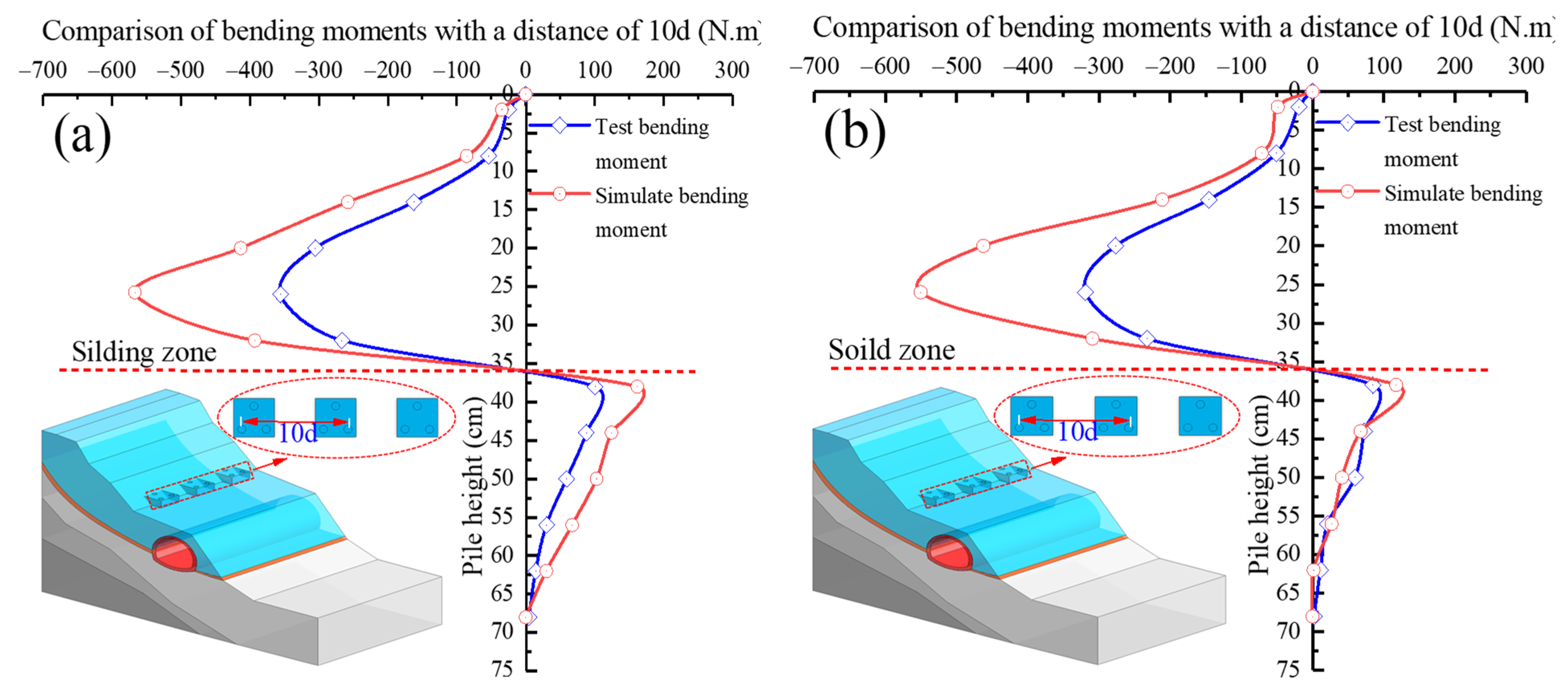
The above numerical simulations are stability and force simulations according to the actual dimensions of the engineering section, and the indoor model tests are 1:30 reduced-scale tests due to the limitation of the conditions. Therefore, when comparing the numerical simulation with the model test pile and the tunnel bending moment, the actual numerical simulation was derived from the obtained bending moments according to the measurement point arrangement, and the results were converted by similarity ratio, as shown in Figure 30, Figure 31, Figure 32 and Figure 33.
It can be seen from the Figure 30, Figure 31, Figure 33 and Figure 34 comparisons between the numerical simulation and the indoor model test with different pile spacing, tunnel, and combined medium-diameter anti-slide piles bending moments that the overall pile and tunnel force trends remain basically the same; as the pile spacing decreases, the landslide load carried by the tunnel is gradually reduced.
As can be seen from the bending moment comparison of Figure 30, Figure 31, Figure 32 and Figure 33, the results obtained in the numerical simulations are generally larger than the model test values; the main reason is that the ideal last damage state can be achieved in the numerical simulations, while the laboratory test is more difficult to complete due to the limitations of the conditions.
In summary, the stress and deformation analysis of the tunnel lining structure under different pile spacings is carried out through both simulation and experimentation. Both methods lead to the same conclusion that as the pile spacing increases (from 7.5 d to 12.5 d), the overall force and deformation in the tunnel lining structure and pile body gradually increase, and it can also be seen that the proportion of force at the foot of the tunnel arch gradually increases. The results obtained from the model tests and the numerical simulations are consistent.
By comparing the displacement, earth pressure, and bending moment of the combined medium-diameter anti-slide pile body and tunnel lining structure during the loading process of the model test, it can be seen that with a gradual increase in the applied load, the combined medium-diameter anti-slide pile and tunnel lining structure, the displacement, the earth pressure, and the bending moment all showed a growth phenomenon, and when the pile spacing was 12.5 d, under the same load, compared with the pile spacings of 10 d and 7.5 d, the tunnel could bear greater displacement and deformation. At the same time, as the pile spacing increased, the load required to damage the model slope body and the anti-slide pile body and tunnel lining damage decreased gradually.
From the test damage phenomenon, displacement distribution law, bending moment, and earth pressure distribution law, it is known that when the pile spacing increased from 7.5 d to 10 d and 12.5 d, due to the increase in the landslide thrust force borne by a single pile, the horizontal displacement of pile top, pile bending moment, tunnel displacement, and tunnel bending moment increase gradually when the same load was applied.
However, the increases in displacement, earth pressure, and bending moment when the pile spacing increased from 7.5 d to 10 d were more significant than those when the pile spacing increased from 10 d to 12.5 d. Taking the model test as an example, when the overall model was subjected to the same maximum load, as the pile spacing increased from 7.5 d to 10 d, the bending moment of the anti-slide pile increased by about 56%, and the earth pressure increased by about 69%. In the same way, the bending moment of the tunnel lining structure in the same case increased by about 52.9%, and the earth pressure increased by about 41%, while when the pile spacing increased from 10 d to 12.5 d, the bending moment of the pile body increased by about 24%, and the earth pressure increased by about 38.7%. Similarly, the bending moment of the tunnel lining structure increased by about 28.1%, and the earth pressure increased by about 19.2% under the same conditions).
Therefore, in the tunnel–landslide system design combination of diameter anti-slide piles, for the consideration of actual engineering economic benefits, if the landslide thrust encountered is small, we can increase some pile spacings to 12.5 d or even larger according to the actual situation, but there are certain restrictions, and increasing the pile spacing should be carefully considered. However, when we encounter a large landslide thrust, we should be able to reduce the pile spacing to 7.5 d or even smaller, which is beneficial for the protection of the tunnel lining structure under landslide action. However, regardless of whether the landslide thrust is large or small, an anti-slide pile spacing of 10 d is the least cost-effective option for landslide management tunnel protection.

6.2. Two-Parameter Fitting Analysis

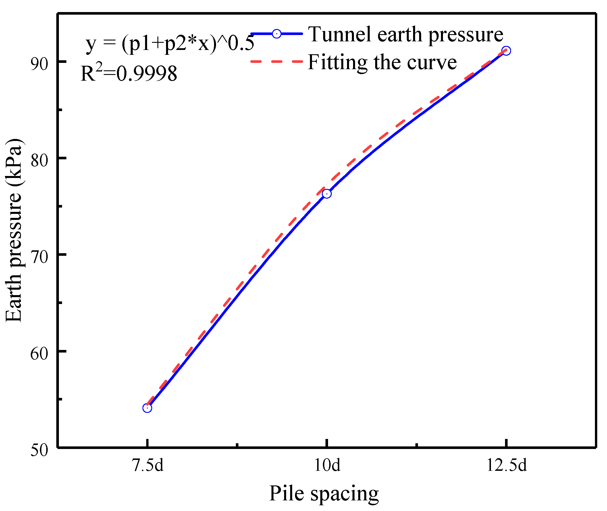
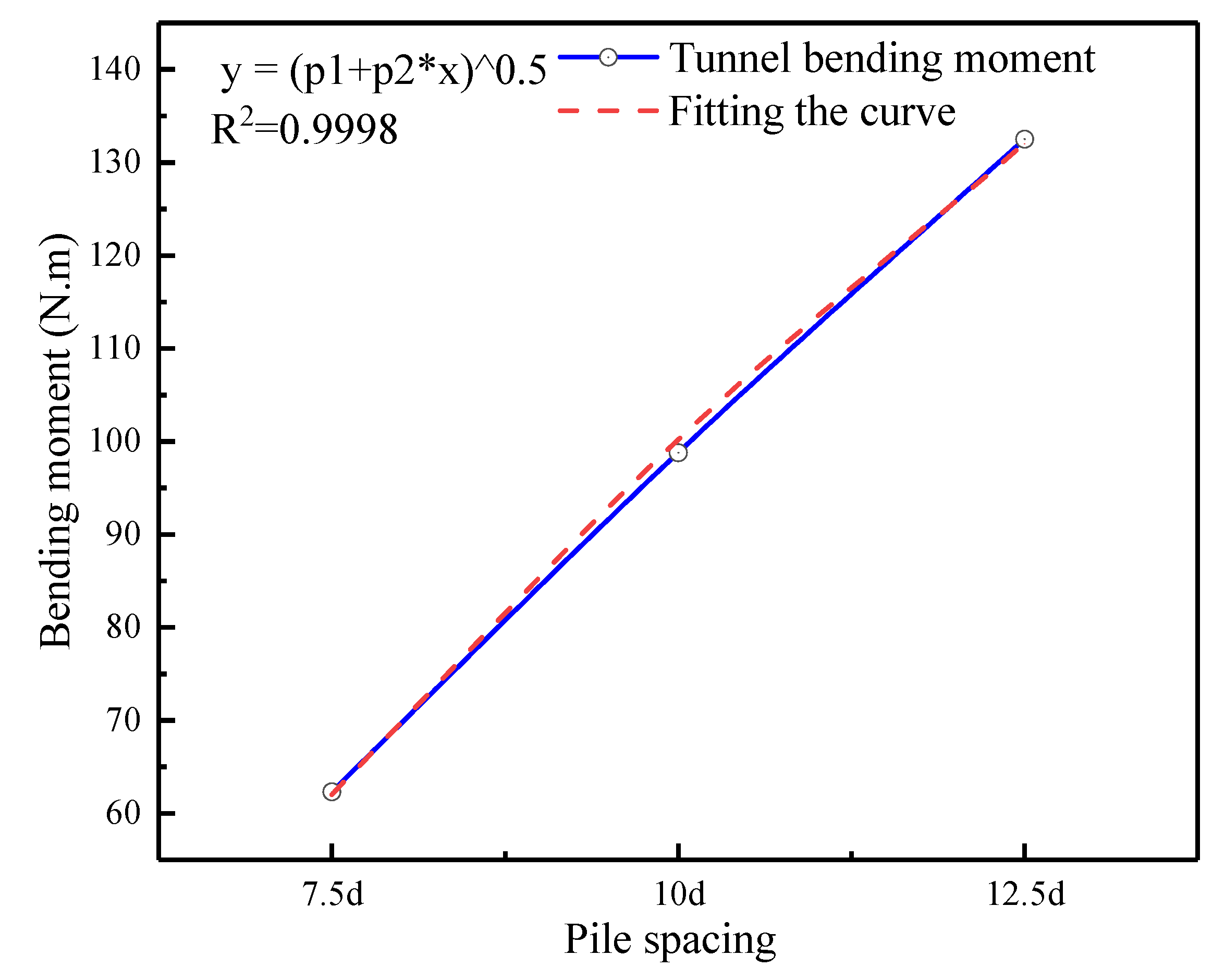
The mapping relationship between the tunnel force and pile spacing can be established by processing the data of earth pressure and bending moment of the tunnel with different combinations of pile spacing, then fitting the test data results and regressing the model parameters through a generalized mathematical model. The optimal two-parameter fitting equation for the tunnel forces under different combinations of pile spacing is established in Equation (11) below:
y = ( p 1 + p 2 x ) 0.5
After establishing a double reference fitting curve for different combination pile spacings, as shown in Figure 35 and Figure 36, the regression model parameters are shown in Table 5. The evolution law between the pile spacing variables and the tunnel force is thus obtained based on the tunnel force relationship under the action of different combination pile spacing. In the process of tunnel stress evolution, in the process of increasing from short-pitch pile spacing to long-pitch pile spacing, there will be a convex increase in the force at the intermediate pile spacing, which is consistent with the results of the previous experimental studies and numerical simulations.
The double-parameter model derived from the evolution of the tunnel force under the effect of different combination pile spacing with step-by-step loading can well describe the tunnel force characteristics in the combination pile spacing change process. The constructed model is consistent with the actual situation in both bending moment and earth pressure, which has some reference significance to the actual project.

7. Conclusions

(1)
During the loading process, the cracks parallel to the direction of the sliding body and the load value of the void area formed gradually decreased, the width and depth of the formed void area gradually became more significant, and the shearing effect on the slope body gradually increased.
(2)
Under the same load, the horizontal displacement of the pile top, horizontal displacement of the tunnel, earth pressure of the pile, and bending moment of pile and bending moment of the tunnel gradually increased with increasing pile spacing, but when the pile spacing increased from 10 d to 12.5 d, the increases in displacement, earth pressure, and bending moment (the bending moment increased by about 24%, earth pressure increased by about 38.7%, the bending moment of the tunnel lining structure increased by about 28.1%, and that earth pressure increased by 19.2%) were much smaller than when the pile spacing increased from 7.5 d to 10 d (the bending moment increased by about 56%, the earth pressure increased by about 69%, the bending moment of the tunnel lining structure increased by about 52.9%, and that earth pressure is increased by 41%).
(3)
Comparing the indoor tests with the numerical simulations showed that the numerical simulation results are highly consistent with the indoor test and further that there were significant differences in the protective effects of the tunnel lining structure under different pile spacings. At the same time, the study of stresses in the tunnel surrounding rock at different pile spacing revealed that the major and minor stresses in the surrounding rock decrease as the pile spacing decrease.
(4)
When supporting existing tunnel–landslide systems, to consider the engineering interests, if the landslide thrust encountered is small, the pile spacing can be increased to 12.5 d or even larger according to the actual situation but with certain restrictions (increasing the pile spacing should be more carefully considered), but when we encounter a large landslide thrust, we should be able to reduce the pile spacing to 7.5 d or even smaller to achieve the effect of the pile in protecting the tunnel lining. However, whether the landslide thrust is large or small, an anti-slide pile spacing of 10 d is less cost-effective for landslide tunnel protection.

Author Contributions

Data curation, B.Z.; Formal analysis, G.C., Y.L. and B.L.; Funding acquisition, T.L. All authors have read and agreed to the published version of the manuscript.

Funding

National Natural Science Foundation of China and Applied Basic Research in Sichuan Province (No. 41672342; No. 2019YJ0555).

Informed Consent Statement

Informed consent was obtained from all subjects involved in the study.

Data Availability Statement

The data presented in this study are available on request from the corresponding author. The data are not publicly available due to article length reason.

Acknowledgments

The authors acknowledge the financial support provided by the National Natural Science Foundation of China and Applied Basic Research in Sichuan Province (No. 41672342; No. 2019YJ0555).

Conflicts of Interest

The authors declare no conflict of interest.

References

  1. Li, T.; Zhu, B.; Bo, L.; Xiong, W.; Luo, B. Study on the bearing characteristics of pile body and tunnel lining structure in tunnel-landslide system with different anti-skid pile spacing. Ind. Build. 2021, 51, 31–38. [Google Scholar]
  2. Baolong, Z.; Qiang, C.; Xiyong, W. Experimental study on force centrifugation model of micro-pile group reinforced slope. J. Sichuan Univ. (Eng. Sci. Ed.) 2012, 44, 1–8. [Google Scholar]
  3. Wu, H.G.; Zhao, J.; Li, Y. Study on Calculation Method of Additional Load under Tunnel Tunnel. Chin. J. Rock Mech. Eng. 2018, 37, 4375–4383. [Google Scholar]
  4. Barla, G. Numerical modeling of deep-seated landslides interacting with man-made structures. J. Rock Mech. Geotech. Eng. 2018, 10, 1020–1036. [Google Scholar] [CrossRef]
  5. Dang, H.K.; Meguid, M.A. Application of a multilaminate model to simulate the undrained response of structured clay to shield tunnelling. Can. Geotech. J. 2008, 45, 14–28. [Google Scholar] [CrossRef]
  6. Gonzalez, C.; Sagaseta, C. Patterns of soil deformations around tunnels. Appl. Ext. Madr. Metro. Comput. Geotech. 2001, 28, 445–468. [Google Scholar] [CrossRef]
  7. Gui, M.W.; Chen, S.L. Estimation of transverse ground surface settlement induced by DOT shield tunneling. Tunn. Undergr. Space Technol. 2013, 33, 119–130. [Google Scholar] [CrossRef]
  8. Hajjar, M.; Hayati, A.N.; Ahmadi, M.M.; Sadrnejad, S.A. Longitudinal settlement profile in shallow tunnels in drained conditions. Int. J. Geomech. 2015, 15, 04014097. [Google Scholar] [CrossRef]
  9. Jin, D.L.; Shen, Z.C.; Yuan, D.J. Effect of spatial variability on disc cutters failure during TBM tunneling in hard rock. Rock Mech. Rock Eng. 2020, 53, 4609–4621. [Google Scholar]
  10. Shahin, H.M.; Nakai, T.; Ishii, K.; Iwata, T.; Kuroi, S. Investigation of influence of tunneling on existing building and tunnel: Model tests and numerical simulations. Acta Geotech. 2016, 11, 679–692. [Google Scholar] [CrossRef]
  11. Zhang, Z.-G.; Zhao, Q.-H.; Xu, C.; Xu, X.-Y. Interaction analyses between tunnel and landslide in mountain area. J. Mt. Sci. 2017, 14, 1124–1139. [Google Scholar] [CrossRef]
  12. Zhang, Y.; Yang, J.; Yang, F. Field investigation and numerical analysis of landslide induced by tunneling. Eng. Fail. Anal. 2015, 47, 25–33. [Google Scholar] [CrossRef]
  13. Causse, L.; Cojean, R.; Fleurisson, J.-A. Interaction between tunnel and unstable slope–Influence of time-dependent behavior of a tunnel excavation in a deep-seated gravitational slope deformation. Tunn. Undergr. Space Technol. 2015, 50, 270–281. [Google Scholar] [CrossRef]
  14. Li, Z.; Huang, H.; Xue, Y. Cut-slope versus shallow tunnel: Risk-based decision making framework for alternative selection. Eng. Geol. 2014, 176, 11–23. [Google Scholar] [CrossRef]
  15. Li, P.; Liu, C.; Zhang, Y.; Zhang, J.; Yang, J.; Feng, T. Construction practice of landslide during tunneling in hilly topography. Eng. Fail. Anal. 2019, 104, 1234–1241. [Google Scholar] [CrossRef]
  16. Shao, J.; Zhu, B.L.; Li, T. Force characteristics of tunnel lining structure under landslide of different sliding belt angles. J. Southwest Jiao Tong Univ. 2021, 56, 1214–1221+1231. [Google Scholar]
  17. Tian, X.; Song, Z.; Zhang, Y. Monitoring and reinforcement of landslide induced by tunnel excavation: A case study from Xiamaixi tunnel. Tunn. Undergr. Space Technol. 2021, 110, 103796. [Google Scholar] [CrossRef]
  18. Zhang, Z.; Fang, L.; Zhao, Q.; Zhang, M.; Pan, Y.; Ma, B. An experimental evaluation of pile-anchor strengthening mechanics for existing tunnels in landslide region. Undergr. Space 2022, 7, 199–218. [Google Scholar] [CrossRef]
  19. Tian, S.; Wu, K.; Liu, D. Concept and technology of active support of weak surrounding rock tunnel. J. China Railw. Soc. 2021, 43, 158–164. [Google Scholar]
  20. Puzrin, A.M.; Schmid, A. Evolution of stabilised creeping landslides. Ge´Otechnique 2012, 62, 491–501. [Google Scholar] [CrossRef]
  21. Friedli, B.; Hauswirth, D.; Puzrin, A.M. Lateral earth pressures in constrained landslides. Ge´Otechnique 2017, 67, 890–905. [Google Scholar] [CrossRef]
  22. Muraro, S.; Madaschi, A.; Gajo, A. Passive soil pressure on sloping ground and design of retaining structures for slope stabilisation. Ge´Otechnique 2015, 65, 507–516. [Google Scholar] [CrossRef]
  23. Wang, Y.-Q.; Ma, C.-B.; Wang, Z.-F. Prediction of landslide position of loose rock mass at mountain tunnel exit. Adv. Civ. Eng. 2019, 2019, 3535606. [Google Scholar] [CrossRef]
  24. Li, T. Study on the Force Characteristics of Medium Diameter Stiffened Steel Pipe Anti-Slide Piles. Master’s Thesis, Southwest University of Science and Technology, Mianyang, China, 2021. [Google Scholar]
  25. Zhao, T.Y.; Yan, K.; Li, H.W.; Wang, X. Study on theoretical modeling and vibration performance of an assembled cylindrical shell-plate structure with whirl motion. Appl. Math. Model. 2022, 110, 618–632. [Google Scholar] [CrossRef]
  26. Zhao, T.; Li, K.; Ma, H. Study on dynamic characteristics of a rotating cylindrical shell with uncertain parameters. Anal. Math. Phys. 2022, 12, 1–28. [Google Scholar] [CrossRef]
  27. Desrues, M.; Lacroix, P.; Brenguier, O. Satellite pre-failure detection and in situ monitoring of the landslide of the Tunnel du Chambon, French Alps. Geosciences 2019, 9, 313. [Google Scholar] [CrossRef] [Green Version]
  28. Chiu, Y.C.; Lee, C.H.; Wang, T.T. Lining crack evolution of an operational tunnel influenced by slope instability. Tunn. Undergr. Space Technol. 2017, 65, 167–178. [Google Scholar] [CrossRef]
  29. Li, C.D.; Tang, H.M.; Hu, X.L. Improved maximum pile interval model of anti-slide pile based on soil arching effect. Geol. Sci. Technol. Inf. 2010, 29, 121–124. [Google Scholar]
  30. Li, C.D.; Tang, H.M.; Hu, X.L. A novel optimal plane arrangement of stabilizing piles based on soil arching effect and stability limit for 3D colluvial landslides. Eng. Geol. 2015, 195, 236–247. [Google Scholar] [CrossRef]
  31. Wang, W.L.; Wang, T.T.; Su, J.J.; Lin, C.H.; Seng, C.R.; Huang, T.H. Assessment of damage in mountain tunnels due to the Taiwan Chi-Chi earthquake. Tunn. Undergr. Space Technol. 2001, 16, 133–150. [Google Scholar] [CrossRef]
Figure 1. Study area.
Sustainability 14 12135 g001
Figure 2. Regional tectonic map of the study area.
Sustainability 14 12135 g002
Figure 3. Schematic geological prototype of Nanping Tunnel.
Sustainability 14 12135 g003
Figure 4. Deformation and damage characteristics of Nanping Tunnel.
Sustainability 14 12135 g004
Figure 5. Schematic diagram of combined medium-diameter anti-slide pile.
Sustainability 14 12135 g005
Figure 6. Illustration of three-stage soil arching of anti-slide pile. (a) Post-pile soil arching; (b) Pile corner soil arching stage; (c) Soil arch between piles.
Sustainability 14 12135 g006
Figure 7. 3D ellipsoidal landslide model (Li C D et al.; 2015) [30].
Sustainability 14 12135 g007
Figure 8. Calculation model for pile spacing.
Sustainability 14 12135 g008
Figure 9. Pile spacing arrangement diagram.
Sustainability 14 12135 g009
Figure 10. Model material cohesion and internal friction angle parameters: (a) sliding body material cohesion and internal friction angle; (b) sliding zone material cohesion and internal friction angle; (c) sliding bed material cohesion and internal friction angle; (d) bedrock material cohesion and internal friction angle).
Sustainability 14 12135 g010aSustainability 14 12135 g010b
Figure 11. Schematic diagram of the landslide model.
Sustainability 14 12135 g011
Figure 12. Tunnel–landslide model test object: (a) Model front view; (b) Model top view.
Sustainability 14 12135 g012
Figure 13. Combined pile and tunnel test model. (a) Pile mould; (b) Combined medium diameter anti-silde pile test model; (c) Tunnel Model.
Sustainability 14 12135 g013
Figure 14. Different pile spacing layout. (a) Schematic of combined medium diameter anti-silde piles; (b) Pile spacing 7.5 d; (c) Pile spacing 10 d; (d) Pile spacing 12.5 d.
Sustainability 14 12135 g014
Figure 15. Measuring point layout. (a) Tunnel strain gauge arrangement; (b) Tunnel micro earth pressure cell arrangement; (c) Pile strain gauge arrangement; (d) Pilemicro earth pressure cell arrangement.
Sustainability 14 12135 g015
Figure 16. Schematic diagram of test loading.
Sustainability 14 12135 g016
Figure 17. Model destruction schematic (ac) sliding mass damage, pile displacement, lower slope crack; (df) pile spacing 7.5 d, 10 d, 12.5 d tunnel displacement.
Sustainability 14 12135 g017
Figure 18. Displacement of the upper slope under different pile spacings.
Sustainability 14 12135 g018
Figure 19. Pile top displacement under different combined pile spacings.
Sustainability 14 12135 g019
Figure 20. Earth pressure distribution of combined medium-diameter anti-slide pile and tunnels under different loads and three different pile spacings: (a) the rear piles of the combined anti-slide pile with a pile spacing of 12.5 d; (b) the combined anti-slide pile with a pile spacing of 12.5 d anti-slide pile front pile; (c) pile spacing 10 d combined anti-middle diameter anti-slide pile rear pile; (d) pile spacing 10 d combined anti-middle diameter anti-slide pile front pile; (e) pile spacing 7.5 d combined anti-middle diameter anti-slide pile behind pile; (f) combined anti-medium-diameter anti-sliding front pile with pile spacing of 7.5 d; (g) tunnel with pile spacing of 12.5 d; (h) tunnel with pile spacing of 10 d; (i) tunnel with pile spacing of 7.5 d unit: kPa.
Sustainability 14 12135 g020
Figure 21. Bending moment with pile spacing of 12.5 d; (a) bending moment of rear pile; (b) bending moment of front pile; unit: N·m.
Sustainability 14 12135 g021
Figure 22. Bending moment with pile spacing of 10 d: (a) bending moment of rear pile; (b) bending moment of front pile; unit: N·m.
Sustainability 14 12135 g022
Figure 23. Bending moment with pile spacing of 7.5 d: (a) bending moment of rear pile; (b) bending moment of front pile; unit: N·m.
Sustainability 14 12135 g023
Figure 24. Bending moment of tunnel when P = 35 kN: (a) pile spacing of 12.5 d; (b) pile spacing of 10 d; (c) pile spacing of 7.5 d (the negative bending moment in this paper is in tension, and the positive moment is in compression; the inner side of the tunnel bending moment is in compression, and the outer side is in tension).
Sustainability 14 12135 g024
Figure 25. Schematic representation of numerical simulation models for different pile spacings: (a) 7.5 d pile spacing model; (b) 10 d pile spacing model; (c) 12.5 d pile spacing model.
Sustainability 14 12135 g025
Figure 26. Numerical simulation displacement cloud diagram: (a) Tunnel displacement under original landslide thrust. (b) Tunnel-pile displacement under pile spacing of 12.5 d. (c) Tunnel-pile displacement under pile spacing of 105 d. (d) Tunnel-pile displacement under pile spacing of 7.5 d Pile displacement; unit: m.
Sustainability 14 12135 g026
Figure 27. Distribution of tunnel stress clouds (a) original landslide tunnel stress clouds; (b) pile spacing 12.5 d tunnel stress clouds; (c) pile spacing 10 d tunnel stress clouds; (d) pile spacing 7.5 d tunnel stress clouds.
Sustainability 14 12135 g027
Figure 28. Tunnel surrounding rock stress distribution: (a) major principal stresses; (b)minor principal stresses; Unit: kPa.
Sustainability 14 12135 g028
Figure 29. Numerical simulation of pile moment distribution: (a) post pile moment at 12.5 d diameter pile spacing in combination; (b) front pile moment at 12.5 d diameter pile spacing in combination; (c) post pile moment at 10 d diameter pile spacing in combination; (d) front pile moment at 10 d diameter pile spacing in combination; (e) post pile moment at 7.5 d diameter pile spacing in combination; (f) front pile moment at 7.5 d diameter pile spacing in combination; unit: kN·m.
Sustainability 14 12135 g029
Figure 30. Numerical simulation of the tunnel moment cloud distribution: (a) pile spacing 12.5 d tunnel moment; (b) pile spacing 10 d tunnel moment; (c) pile spacing 7.5 d tunnel moment; unit: kN·m.
Sustainability 14 12135 g030
Figure 31. Comparison of numerical simulation and model test 12.5 d pile spacing anti-slide pile bending moments: (a) pile bending moment after diameter anti-slide pile in combination; (b) pile bending moment before diameter anti-slide pile in combination; unit: N·m.
Sustainability 14 12135 g031
Figure 32. Comparison of numerical simulation and model test 7.5 d pile spacing anti-slide pile bending moment: (a) pile bending moment after diameter anti-slide pile in combination; (b) pile bending moment before diameter anti-slide pile in combination; unit: N·m.
Sustainability 14 12135 g032
Figure 33. Comparison of numerical simulation and model test tunnel bending moment: (a) 12.5 d pile spacing tunnel bending moment; (b) 10 d pile spacing tunnel bending moment; (c) 7.5 d pile spacing tunnel bending moment; unit: N·m. (Numerical simulation of bending moment; test bending moment).
Sustainability 14 12135 g033
Figure 34. Comparison of numerical simulation and model test 10 d pile spacing anti-slide pile bending moment: (a) pile bending moment after diameter anti-slide pile in combination; (b) pile bending moment before diameter anti-slide pile in combination; unit: N·m.
Sustainability 14 12135 g034
Figure 35. Fitting of earth pressure parameters for tunnels with different pile spacings.
Sustainability 14 12135 g035
Figure 36. Fitting of bending moment parameters for tunnels with different pile spacings.
Sustainability 14 12135 g036
Table 1. Geological parameters.
Material Name ρ /(kg/m3) E /GPa C/kPaφ/o
Sliding mass1900.000.6227.320.1
Sliding zone1800.000.2816.714.5
Sliding bed2200.001.243.529.2
Bedrock2700.002.5361.233.6
Table 2. Mechanical parameters of model materials.
Material Name ρ /(kg/m3) E /MPa C/kPaφ/o
Sliding mass1900.0018.6526.517.3
sliding zone1800.009.3618.813.5
Sliding bed2200.0023.7248.728.6
Bedrock27,000.0035353.532.1
Tunnel2100.00289.61--
Anti-slid-pile2100.00289.61--
Table 3. Model test loading scheme.
Pile Spacing (cm)Press (kN)Loading Time (Min)Load Holding Time (Min)
15, 20, 250~51520
5~101520
10~152030
15~202030
20~252030
25~303040
30~3530-
Table 4. Mechanical parameters of model materials.
Material NameConstiutive Type ρ /(kg/m3) E/GPaC/kPaφ/o
Sliding massMohr-Coulomb1900.000.6227.320.1
Sliding zoneMohr-Coulomb1800.000.2816.714.5
Sliding bedMohr-Coulomb2200.001.243.529.2
BedrockMohr-Coulomb2700.002.5431.233.6
TunnelElasticity2500.0010.4--
Anti-slid-pileElasticity2500.0010.4--
Table 5. Regression values of two-parameter dilatancy angle model parameters under different pile spacings.
TypeP1P1
Earth pressure−79,630.25512,420.445
Bending moment−16,521.592715.800
Publisher’s Note: MDPI stays neutral with regard to jurisdictional claims in published maps and institutional affiliations.