Article

Study on Design and Deformation Law of Pile-Anchor Support System in Deep Foundation Pit

1
College of Water Resources & Civil Engineering, China Agricultural University, Beijing 100083, China
2
China Geo-Engineering Corporation, Beijing 100093, China
*
Author to whom correspondence should be addressed.
Sustainability 2022, 14(19), 12190; https://doi.org/10.3390/su141912190
Submission received: 31 July 2022 / Revised: 30 August 2022 / Accepted: 19 September 2022 / Published: 26 September 2022

Abstract

:
In this study, a deep foundation pit project of Nanlishi Road in the Xicheng District of Beijing was taken as the engineering background. Based on the monitoring method of that project and referring to its design scheme principle, this study applied advanced monitoring technology methods such as anchor axial force and deep horizontal displacement monitoring. The mechanism of pile–soil interaction, the stress change and deformation law of the three-pile and two-anchor support systems of deep foundation pits, and the stability of deep foundation pit support in an anhydrous sandy pebble stratum, were studied in depth. Results show: The axial force of the anchor rod had great loss in the early stage of prestressed tension locking; with the deepening of foundation pit excavation, the lateral pressure of stratum increased gradually, and the prestress of the anchor increased until the end of excavation, where it tended to be stable; the maximum horizontal displacement of the pile was smaller than the design value, and the maximum horizontal displacement was not at the top of the pile; the axial force of the prestressed anchor varied with the formation pressure and surrounding load; the tension of the lower anchor had a certain influence on the axial force of the upper anchor. Except for the east side of the foundation pit, the anchors of the first layer were all stabilized at about 140 kN, and the anchors of the second layer were stabilized at about 150 kN. The third row of anchors on the north side was stable at around 170 kN. By analyzing the variation law of stress and deformation of the supporting structure of the foundation pit, the timeliness of the data during the construction process was improved, and a reference is provided for the informatization construction of related working conditions.

1. Introduction

At present, with the continuous advancement of urbanization, the corresponding requirements for the development and utilization of urban underground space have promoted deep foundation pit engineering into a period of rapid development [1,2].
The application of information construction technology can compare and analyze the monitoring data collected during construction with the original design scheme [3,4,5,6,7], evaluate the scientificity of the construction, and put forward reasonable suggestions to guide the construction and design in the next stage to achieve the purpose of dynamic optimization.
The monitoring of a deep foundation pit has timeliness and unique accuracy requirements [8,9,10,11,12]. The monitoring results vary with the excavation depth, environmental conditions, and construction procedures at any time, and generally require high accuracy in accuracy control. Therefore, in the monitoring process, the accuracy of foundation pit monitoring is often ensured by using advanced high-precision monitoring instruments or by selecting reasonable control methods. Terzaghi studied the stability of excavated soil and the internal force of support as early as the early 20th century, and the monitoring of foundation pit excavation in Oslo occurred in the 1960s. Peck [13] proposed the research method of the geotechnical engineering monitoring observation method. Subsequently, the United States and Japan, as well as other countries, have carried out the research and application of engineering monitoring technology specifications [14,15,16], which greatly developed the deep displacement monitoring of foundation engineering, internal force monitoring, and the analysis of supporting structures. The literature [17,18,19,20,21] applied BP network technology combined with different algorithms and other risk analysis methods, in the health monitoring of building structures and deep foundation pits, which has a strong predictive ability in ensuring the safety and stability of the structure. The literature [22,23,24,25,26,27,28] analyzed the layout principle of monitoring points in the monitoring process of deep foundation pit horizontal displacement, settlement, anchor prestress, soil nail stress, slope water, and soil pressure, through specific engineering examples and field tests, monitoring schemes, data acquisition, and processing and analysis, and summarized the stress and deformation laws. The literature [11,29,30,31,32,33,34,35] applied the theory to the monitoring data processing and inversion analysis to obtain the support structure and stratum stress, compared them with the design results to evaluate the rationality of the design, and discussed the corresponding improvement methods from a theoretical perspective. The literature [36,37,38,39] proposed a three-dimensional space effect of the foundation pit retaining structure deformation by monitoring a deep foundation pit in soft soil. The literature [40,41,42], combined with the monitoring data of the whole construction process, studied the influence of deep foundation pit excavation on an existing adjacent building structure. The literature [43,44,45] summarized the main problems existing in deep foundation pit engineering and pointed out that engineering monitoring was the basis of information construction. Monitoring research should be strengthened to promote the establishment of an information construction management system.
The excavation and support of a deep foundation pit mainly adopt economic and safe support structures to limit the deformation caused by soil excavation. The pile-anchor support technology is widely used because of its low cost, wide applicability, and simple construction. In recent years, with the development of computer technology and the improvement of monitoring levels, the research on the pile-anchor supporting structure has been greatly improved. The literature [46,47,48,49] established a functional relationship between prestressing and anchor stability on the basis of considering the prestress of the anchor. The literature [50,51,52,53] studied the deformation and stress changes of the supporting structure, caused by the failure of the pile-anchor in a deep foundation pit, by the finite difference method and put forward that the failure of the local anchor had a great influence on the stability of the foundation pit. The literature [54,55,56,57] used the finite difference principle to study the frost heaving force on the foundation pit pile-anchor support system and discussed the stress change and deformation law of foundation pit pile-anchor support under low-temperature conditions. The literature [58,59] optimized the supporting structure of the pile-anchor foundation pit, considering the corner effect.
In this study, a deep foundation pit project of Nanlishi Road in the Xicheng District of Beijing was taken as the engineering background. By using the methods of theoretical analysis and field monitoring, the pile-anchor support system of deep foundation pits, the mechanism of pile–soil interaction, the stress variation law and deformation law of deep foundation pits supported by three piles and two anchors, and the stability of deep foundation pits supported in anhydrous sandy cobble stratum were studied in depth, and the information construction technology suitable for engineering practice was explored for reference for similar engineering construction in the future.

2. Deep Foundation Pit Excavation Monitoring and Support Scheme Design

This study took Nanlishi Road in Xicheng District of Beijing as the engineering background, and the engineering structure was composed of 3 underground layers, part of 4 layers, and 13 above-ground layers. It was a frame and shear wall structure, the foundation depth was 16.67–20.47 m, and the external wall was 84.30 m × 75.40 m.

2.1. Engineering Geological Condition

The project site was located in the upper and middle parts of the Yongding River alluvial fan with flat terrain. According to the survey report, the construction site was mainly divided into the artificial filling and quaternary clay silt, fine sand, pebble layer, etc. The composition and physical and mechanical indexes of each layer of soil are shown in Table 1.

2.2. Surroundings around the Foundation Pit

The available space in the site around the foundation pit was small. The east side was adjacent to the hostel, on the south side and the west side were the municipal roads, on the west side was the present residence, and on the north side was the present residence. Figure 1 is the plan of the surrounding environment of the foundation pit. The meaning of the symbols is shown in Table 2.

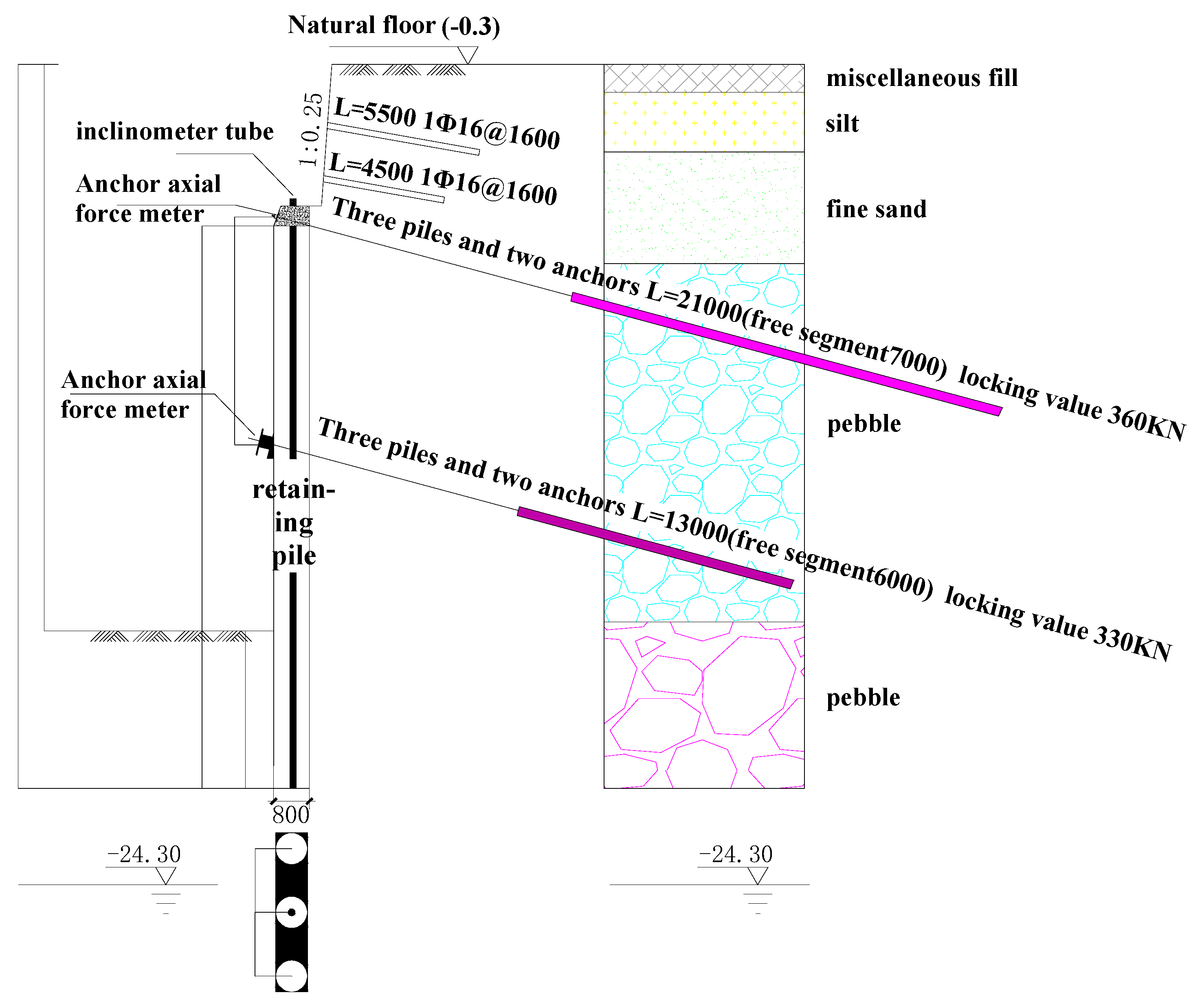
2.3. Design of Foundation Pit Support Scheme

The importance level of this foundation pit was of the first grade. The soil nailing wall and pile-anchor support form was adopted. According to the different surrounding environments and depth of the foundation pit, the design of the foundation pit support was divided into four sections. Taking the west section of the foundation pit excavation depth of 17 m as an example, the design of the support scheme was introduced.
This section design mainly refers to the ‘building foundation pit support technical specification’ JGJ 120-99, using Lizheng deep foundation pit software design, an internal force calculation method using the elastic method model. Since the elastic method assumes the rectangular distribution of soil pressure, and the classical method assumes the triangular distribution of soil pressure, although the bending moment and shear force calculated by the elastic method and the classical method was close, the internal force and displacement calculated by the elastic method were larger, and the calculation was relatively conservative.
The importance coefficient of the side wall of the foundation pit was 1.10, and it was assumed that the load of the upper 4 m of soil nailing wall was converted into the uniform load of 90 KPa ground pressure. The design and calculation of the foundation pit excavation support mainly involved soil pressure calculation, pile embedded depth calculation, internal force and deformation calculation, pile section reinforcement calculation, anchor cable and soil nailing calculation, overall stability checking calculation, and anti-dip. Therefore, the process of structural calculation should be carried out according to the working conditions of step-by-step excavation and step-by-step support. After the foundation pit excavation and support calculations, the results were collected, and the envelope diagram of the internal force and displacement of the supporting pile is shown in Figure 2.
According to the design results, the maximum horizontal displacement of the foundation pit was 10.03 mm, approximately 7 m below the pile top. Therefore, not only should horizontal displacement monitoring of the pile top and pit top be carried out, but the deep horizontal displacement of the pile body should also be monitored. The maximum bending moment inside the foundation pit was 370.30 kN·m, which was 4 m below the pile top. The maximum shear force inside the foundation pit was 334.03 kN, which was 6 m below the pile top.
The calculation method of integral stability of the foundation pit was the Sweden slice method, and the calculation method of the stress state was the total stress method. The width of the soil strip was 0.5 m, and the safety factor was 2.145.
The calculation formula of foundation pit anti-tilting is as follows:
K s = M p M a
in the formula:
  • M p 
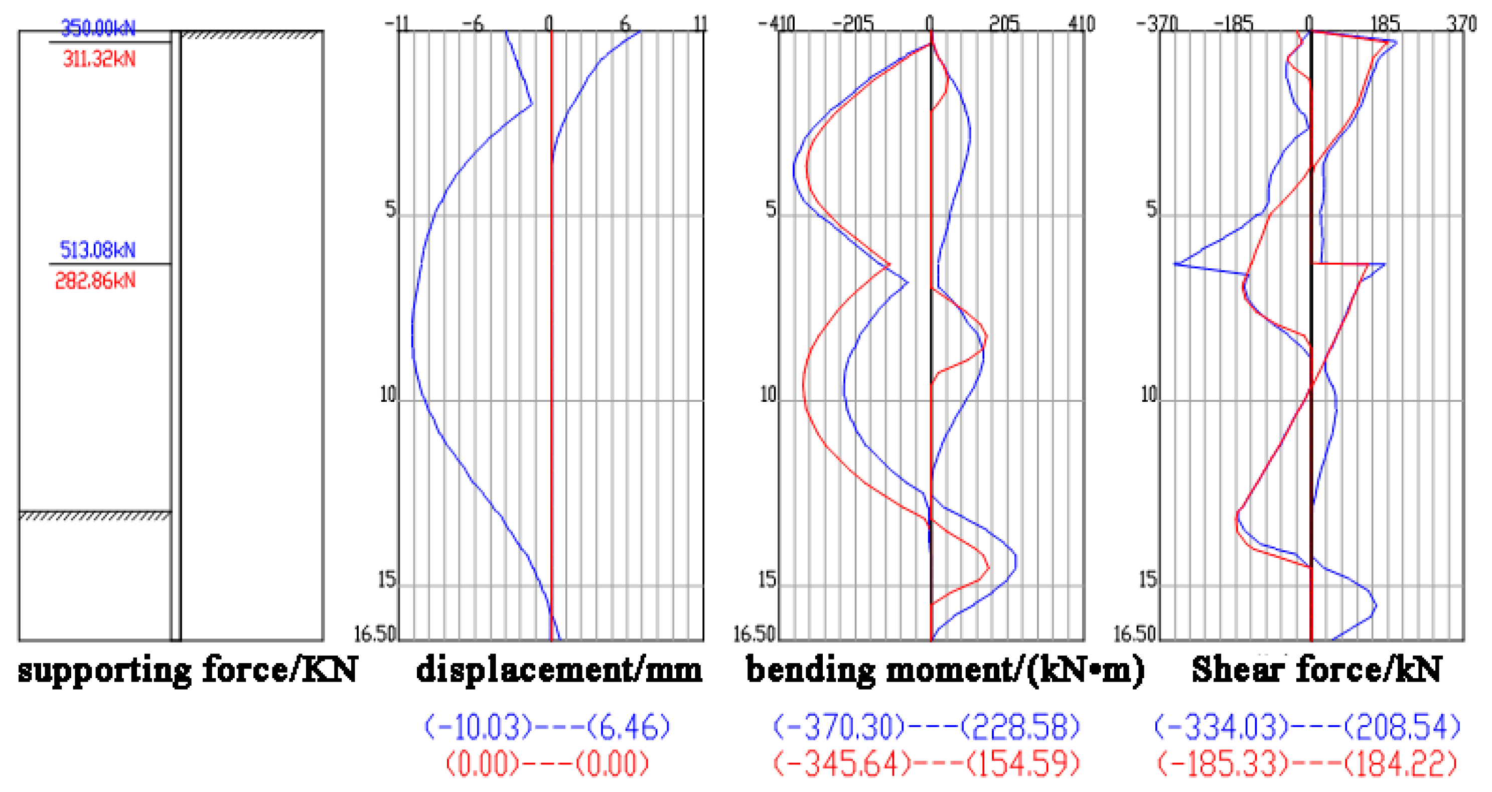
—Passive earth pressure and fulcrum force to the bending moment of the pile bottom; the fulcrum force in this paper takes the smaller value of the anchoring force and the tensile force of the anchor;
  • M a —Bending moment of active earth pressure on the pile bottom.
The calculated safety factor was 1.71, which is greater than the value of 1.2 required by the above specification and meets the engineering safety requirements.
The anti-uplift safety factor of this project was taken from “Technical Specification for Construction Foundation Pit Engineering” YB 9258-97. Due to the difference in the parameter values of the Prandall formula and the Terzaghi formula in the anti-uplift calculation formula, the two formulas were used for calculation at the same time in this project, and the anti-uplift safety of the foundation pit was verified according to the smaller value. The basic formula of the anti-bump check calculation is as follows:
K s = γ DN q + cN c γ ( H + D ) + q
The values of Nq and Nc calculated by the Prandall formula are as follows:
N q = ( tan ( 45 ° + φ 2 ) ) 2 e π tan φ
N c = ( N q 1 ) 1 tan φ
The calculated safety factor was 55.59, which is greater than the specification requirement of Ks ≥ 1.1–1.2.
The values of Nq and Nc calculated by the Terzaghi formula are as follows:
N q = 1 2 e ( 3 π 2 φ 4 ) tan φ cos ( 45 ° + φ 2 )
N c = ( N q 1 ) 1 tan φ
The calculated safety factor was 72.33, which is much higher than the standard value of 1.15–1.25 and meets the safety and stability requirements of the foundation pit.
After the excavation of the foundation pit, the rebound deformation caused by unloading, the lateral displacement of the bottom of the slope protection pile, or the swelling of the bottom of the foundation pit, causes the bottom to heave, which leads to the instability and failure of the foundation pit. Therefore, it is particularly important to check the stability of the foundation pit. The calculation of the heave at bottom of foundation pit is:
δ = 875 3 1 6 ( i = 1 n γ i h i + q ) + 125 ( D H ) 0.5 + 6.37 γ c 0.04 ( tan ) 0.54
in the formula:
  • δ—Upward displacement of the foundation pit bottom (mm);
  • n—Soil layers from top to bottom of the foundation pit;
  • γ i —The gravity of the i-layer soil (kN/m3);
  • h i —The thickness of the i-layer soil (m);
  • q—Ground overload on the top of the foundation pit (kPa);
  • D—Pile embedding length (m);
  • H—Excavation depth (m);
  • c—Soil cohesion at the pile bottom (kPa);
  • —Internal friction angle of the soil layer at the pile bottom (°);
  • γ —Weighted average weight of soil layers from top to bottom of the pile (kN/m3).
Because the bottom of the foundation pit was an anhydrous sandy cobble stratum, the uplift was small. The uplift at the bottom of the foundation pit was calculated to be 3 mm.
In this project, the calculation result of the exponential method was the warning value of settlement observation. The settlement was 33 mm, and the maximum displacement was about 4 m behind the edge of the foundation pit.
Figure 3 shows the supporting structure of the foundation pit. The crown beam was designed to be 4.00 m below the ground, and the first layer of the anchor was laid on the crown beam. A concrete retaining wall with a height of 4.00 m and a thickness of 370 mm was built on the pile tops on the east and south sides of the foundation pit, and graded sand was filled behind the wall. Two rows of soil nailing were arranged behind the retaining wall. The length of the first row of soil nailing was 5.00 m, and the second row of soil nailing was 4.00 m. The vertical spacing was 1.50 m, and the horizontal spacing was 1.60 m. The reinforced retaining wall was connected with the retaining wall structural column. Soil nailing wall support was on the west and north sides of the foundation pit.
The site stratum was mainly sandy cobble stratum, manually excavated cast-in-situ pile with excavation and lining, with hole formation by casing follow-up in the anchor construction. The concentrated load of the buildings around the foundation pit was considered according to 20 kPa per floor, without considering the additional load of groundwater. See Table 3, Table 4 and Table 5 for the specific design parameters of the foundation pit support:

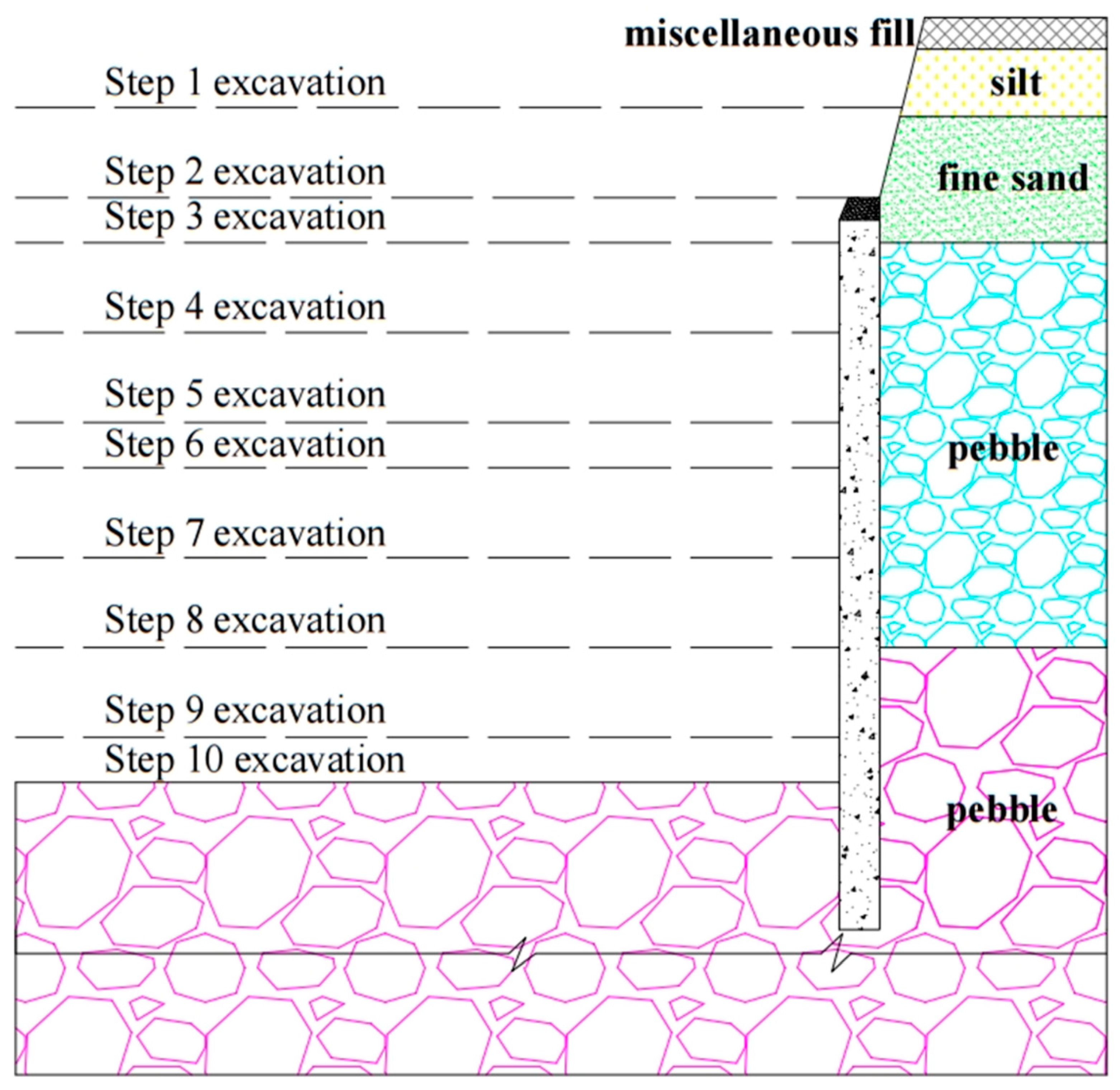
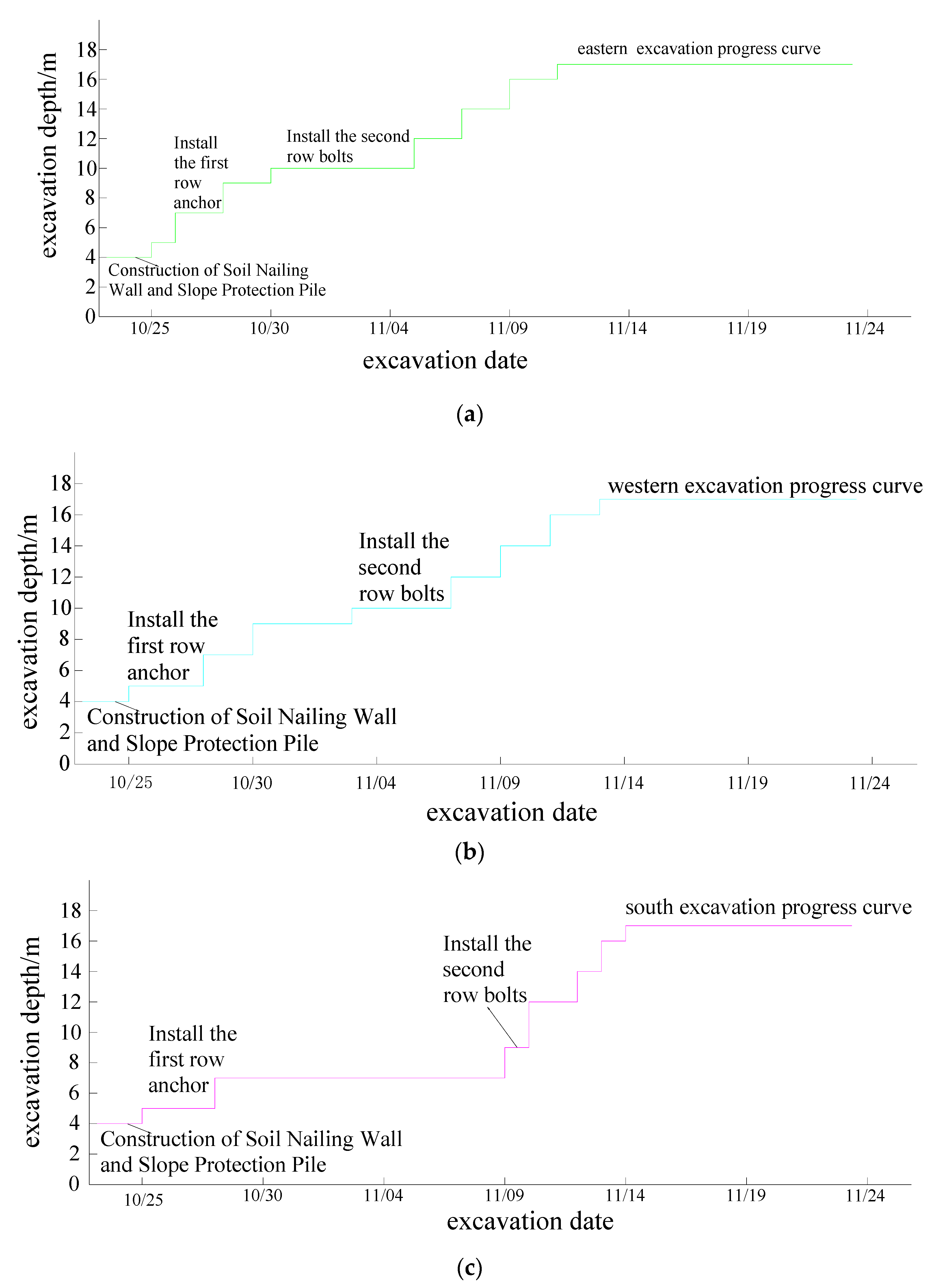
2.4. Excavation Steps of Foundation Pit

Because the excavation construction of the foundation pit had an obvious time and space effect in the step-by-step excavation construction process, and the excavation depth of each step was strictly controlled, over-excavation was strictly prohibited. Because the site stratum was mostly sandy and cobble layers and the excavation depth was 17 m, a design of ten steps of excavation was used, with the excavation depth of each step being 2 m. Another two-step layered excavation was added at the depth of 20 m on the north side of the foundation pit. The specific excavation steps are shown in Figure 4.
Due to the large horizontal area of the foundation pit, the excavation and support of each layer were alternately designed. The south side of the foundation pit was designed as an earthwork carriageway. The middle excavation interval was large, the actual excavation time was short, and the progress was fast. Detailed excavation progress is shown in Figure 5.

3. Deep Foundation Pit Monitoring

In the supporting structure of the pile-anchor structure, to ensure the safety of construction, the anchor force and pile displacement must be within the allowable range of the design in the whole excavation construction process; otherwise, the foundation pit will be unstable or collapse. This project adopted the information construction method. During the construction of foundation pit engineering, the stress and deformation of the foundation pit support structure, surrounding buildings, important roads, and underground pipelines are systematically monitored to ensure the safety of the foundation pit and surrounding environment. Then, the monitoring data and design parameters are compared, the correctness and rationality of the design are analyzed, and the next process is scientifically and reasonably arranged.

3.1. Monitoring Equipment

The MJ-101 vibrating wire anchor dynamometer was used to monitor the prestress of the anchor. When the axial force of the anchor is applied to the dynamometer, the electromagnetic coil excites the steel string, measures its vibration frequency, and reads the frequency value to calculate the load value.
The CX-06A borehole inclinometer was used to monitor the depth of the horizontal displacement of the piles. The horizontal displacement variation of boreholes in the whole depth range was obtained by measuring the inclined tube in the pile. The working principle of the inclinometer is mainly to measure the change of arc angle based on the plumb line. When the soil changes, the inclinometer tube also changes. If the detection probe is measured from bottom to top in the inclinometer tube, the inclination of each measurement depth can be measured. Since the measurement interval of each section is fixed, the inclination change in each depth can be measured, and its horizontal displacement increment can be obtained. The total displacement of the hole can be obtained by accumulating the horizontal displacement increment of each section from top to bottom. According to the full-hole measurement results, the displacement profile of each point of the borehole axis can be described to determine the location, size, and direction of the internal displacement of the soil.
According to the previous engineering monitoring and simulation analysis (Figure 4), it can be seen that the deformation amount and deformation rate were the largest in the middle of the foundation pit slope and at the place where the excavation depth changed, while the displacement of the negative angle at the corner of the foundation pit was the smallest, due to the mutual restraint of the two vertical edges, and the soil of the foundation pit slope was relatively safe. Therefore, in this project, the inclinometer tube was poured into a piling body in the middle of the foundation pit or at the place where the depth of the foundation pit bottom changed (Figure 5).

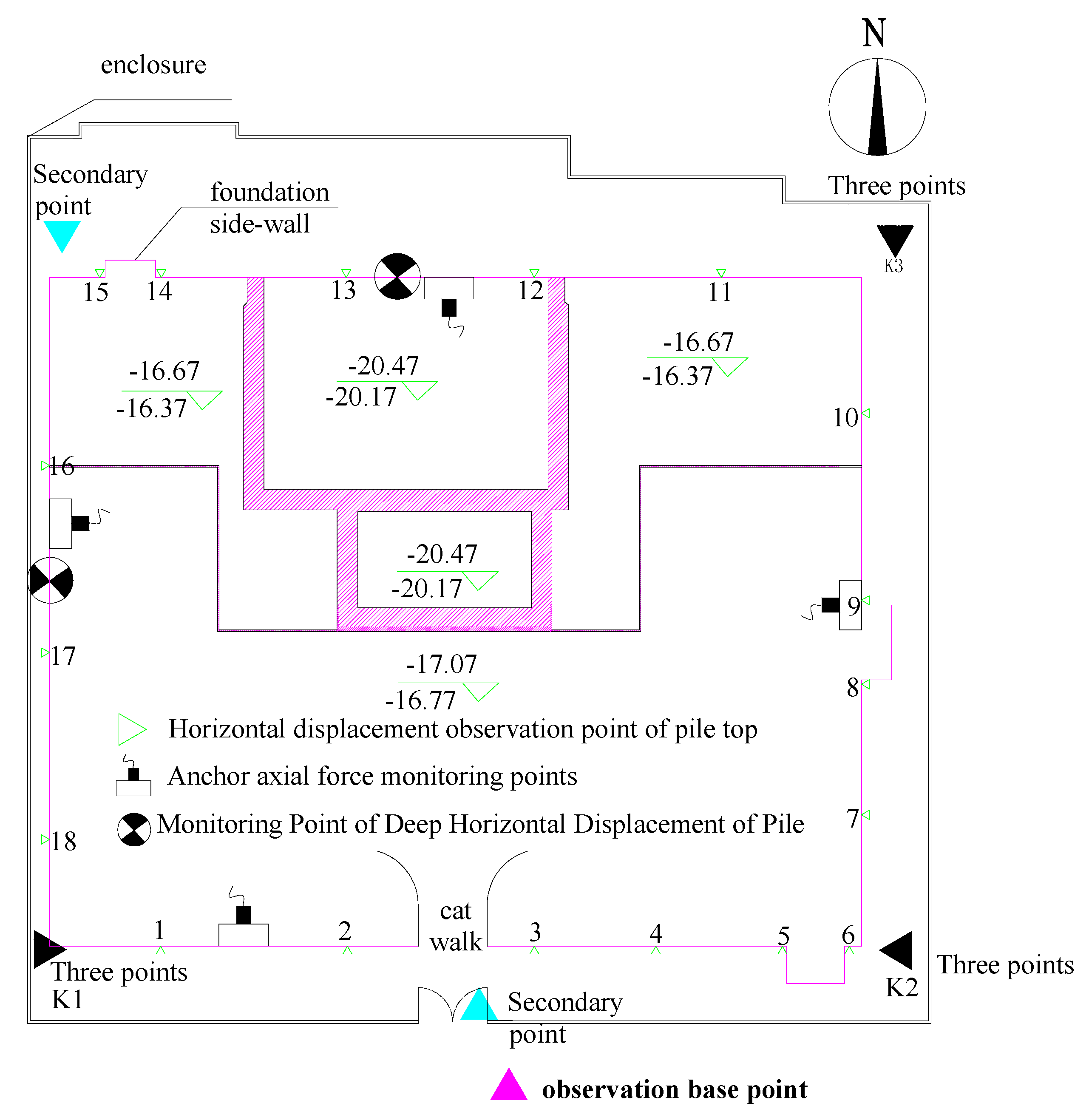
3.2. Monitoring System Layout

During the excavation of the foundation pit, the axial force of the anchor rod and the horizontal displacement of the deep layer were observed once a day, and the monitoring was to be encrypted and supplemented when the excavation of each layer, rainfall, and slope-top loading occurred. When the deformation rate was greater than 2 mm/day, it was to be monitored continuously. When the surrounding load changed little at the end of the foundation pit excavation and foundation construction stage, and the deformation rate was less than 2 mm/day, the monitoring interval could be extended to 2–3 times a week.
The early warning value of foundation pit deformation was controlled by a depth of 0.2%, and the early warning value of the axial force of prestressed anchors was controlled by a design value of 120%.
The observation base points were set at a relatively stable location outside the foundation pit, and the second and third base points were set at the edge of the foundation pit as the horizontal displacement observation benchmark at the top of the slope. The observation error was less than 1 mm by theodolite. Because the west side of the foundation pit was the municipal road and the north side was the main load accumulation area, the deep horizontal displacement observation hole was set up on the north side and the west side of the foundation pit, and the inclinometer was used to observe. The vibrating wire anchor dynamometer was set at the midpoint and elevation angle of each side of the pit wall for prestress monitoring. The horizontal displacement and settlement observation points of the slope top were set on the coupling beam of the pile top of the slope protection pile, and the spacing was not more than 20 m. The measuring points were located in the middle of the pit wall and the corner. The building settlement observation point was located on the building wall. For regular settlement observation with an electronic level, each observation error should be less than 1 mm. The observation layout is detailed in Figure 6.

4. Analysis of Monitoring Results

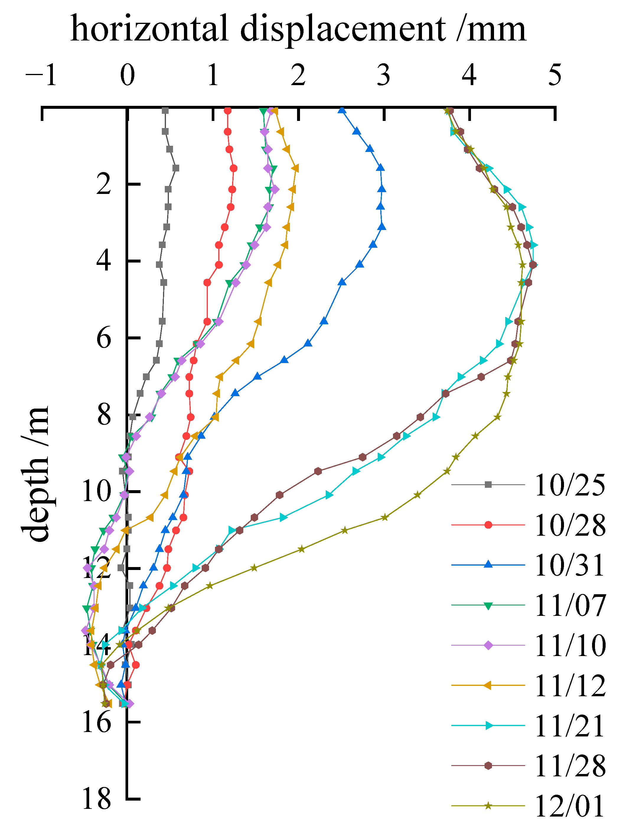
4.1. Horizontal Displacement Analysis

The horizontal displacement of the pile was measured periodically according to the monitoring scheme and the change of weather, construction technology, and surrounding environmental load in the actual construction. According to the monitoring data of the construction process, the horizontal displacement curve of the supporting pile on the west side of the foundation pit were obtained, as shown in Figure 7 and Figure 8.
As can be seen from Figure 6 and Figure 8, with the excavation of the foundation pit, the lateral earth pressure was formed by the horizontal extrusion of the soil on the side wall of the foundation pit due to the excavation unloading, and the position corresponding to the maximum stress of the soil moved down with the depth of the excavation. At the same time, the horizontal displacement of the pile gradually increased, and the maximum displacement position moved down. Finally, the maximum horizontal displacement of the west side of the foundation pit was stable at 4.5 m below the pile top (Figure 7). During the excavation of the foundation pit, the horizontal displacement change rate of the pile was large, and the horizontal displacement rate decreased until it tended to be stable after the construction.
As can be seen from Figure 8, the west side of the foundation pit was adjacent to the municipal road, and the vehicle passed through the soil behind the foundation pit wall to form a large dynamic load. In addition, the retaining structure was set on the roadside frame during the construction period, which caused the horizontal displacement of the pile to change complexly, and the displacement of the pile top was relatively large, reaching 3.72 mm. Then, the second row of anchors in the foundation pit was tensioned, so that the pile body moved outward by the active constraint force to the outside of the foundation pit. With the increase of the depth of the foundation pit and the combined action of the prestress loss of the two rows of anchors and the dynamic load of the pit wall in the subsequent excavation, the horizontal displacement of the foundation pit increased significantly until it was stabilized to 4.61 mm after excavation to the bottom of the pit.
The ground conditions of the site were good, the supporting pile could make full use of the embedded force of sandy cobble stratum and the active force of the prestressed anchor rod, and finally, it was ensured that the overall displacement of the pile was small, and the maximum displacement in the excavation process was within the range of the early warning value.

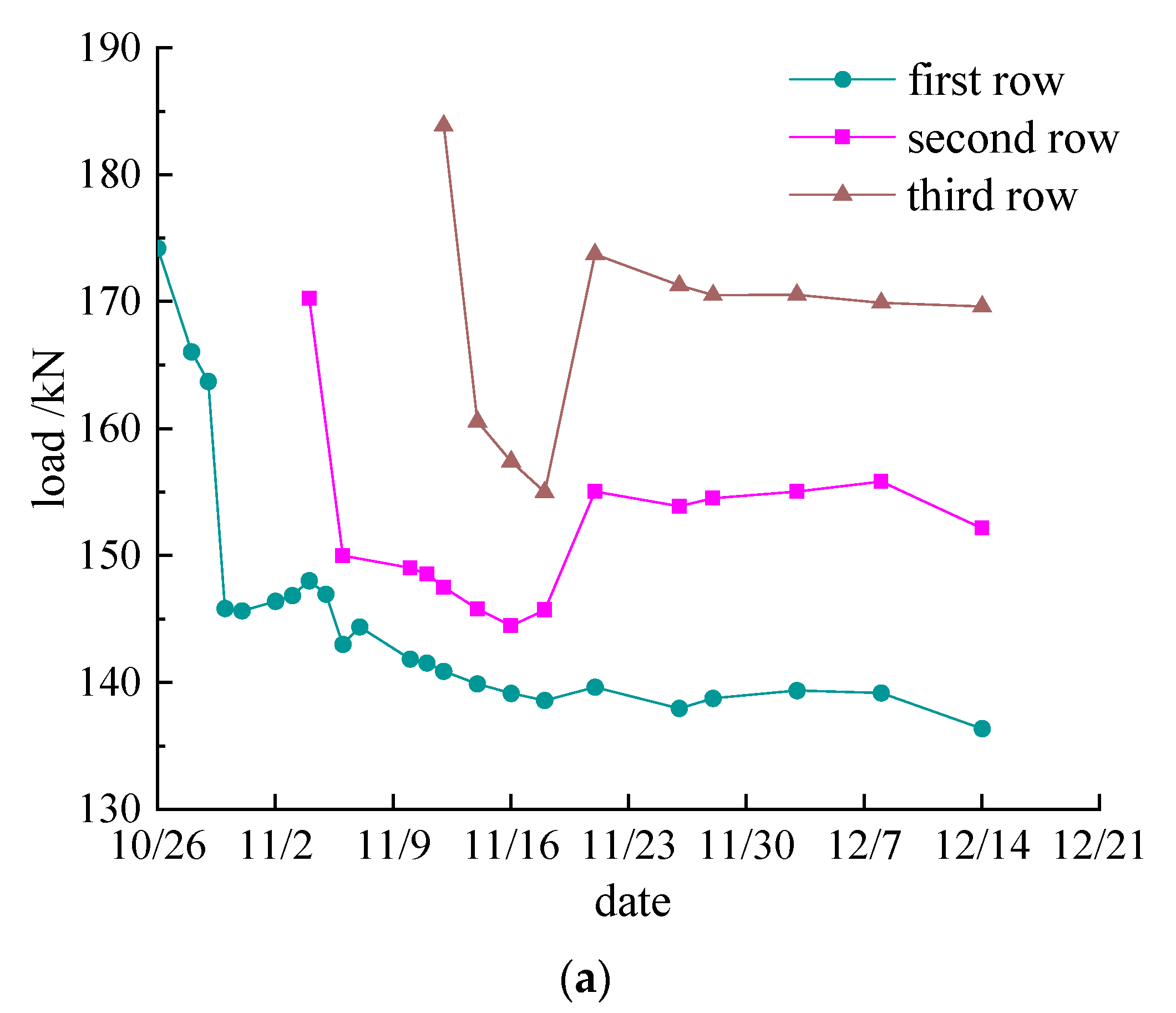
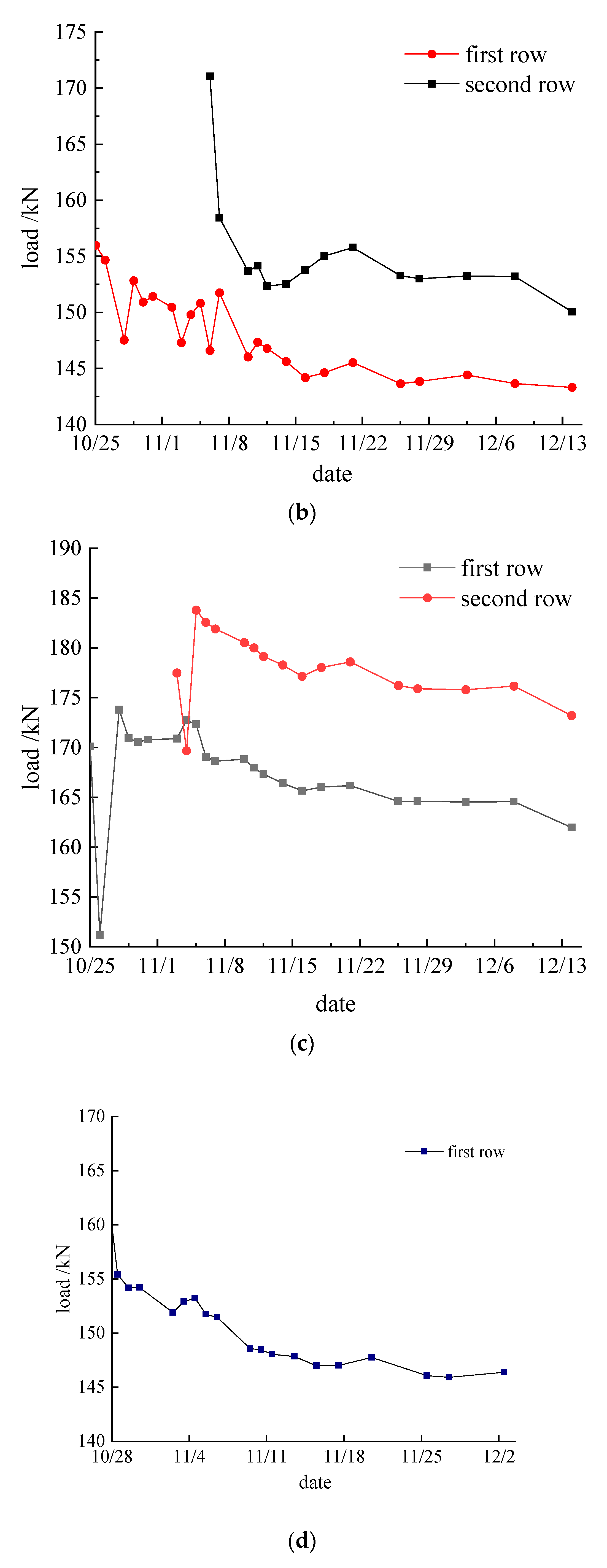
4.2. Analysis of Prestressed Anchor

A prestressed anchor axial force meter was arranged around the foundation pit. The pit wall on the west side of the foundation pit was a single linear type, and the axial force of the anchor was set at the first and second rows of prestressed anchors in the same vertical section. Since the excavation depth of some areas on the north side of the foundation pit reached 20 m, the design was increased from the original two rows to three rows. At the same time, three rows of anchor axial force meters were set in the same vertical section in the middle of the foundation pit. During the excavation of the foundation pit, most areas in the south were excavated roads. The self-weight of the soil in the pit could inhibit the rebound of the foundation pit bottom and balance the lateral soil pressure of the foundation pit sidewall, and the mechanical properties were relatively stable. Therefore, it was possible to just observe the axial force of the first row of bolts exposed in the early construction.
Before the construction of the prestressed anchor, the anchor axial force meter was calibrated, and the tension test of the construction anchor was carried out. An anchor whose compressive strength was greater than 15 Mpa and reached 75% of the design strength was selected for a tension test to determine the tension locking equipment, process, and specific tension parameters.
In this project, the first row of anchors was selected for the tension test. The maximum design tension value was 429 kN, and the design locking tension value was 360 kN. During the formal tension, the cable dynamometer was monitored in time, and the loading rate and angle were adjusted. The data could be read only after the loading of each stage was stable. The specific grading loading parameters were as shown in Table 6:
It can be seen from Table 7 that during the tension process, the tensile force of the prestressed anchor rod increased linearly with the maximum value of 208.15 kN, which is 57.82% of the theoretical value of 360 kN. The actual locking value of the test anchor was 177.56 kN, which is 49.32% of the design locking value of 360 kN. It can be seen that the actual maximum prestress in the tension process had a large gap with the theoretical value, and the loss of locking instantaneous prestress was small, which showed that it could meet the engineering requirements.
As can be seen from Figure 9a, the variation trend of the three rows of prestressed anchors on the north side of the foundation pit tended to be consistent, which was manifested as the fluctuation of the prestress under the combined action of the formation pressure and the anchor itself after the locking of the prestressed anchor, until the end of the foundation pit excavation, after which it tended to be stable. Although the axial force of the measured anchor was much smaller than the design lock value, due to the good site conditions, the support pile was embedded in the anhydrous sandy cobble stratum, and the axial force of the anchor did not show an obvious prestress increase due to the excavation of the foundation pit. This shows that the axial force of the anchor was enough to balance the earth pressure of the stratum during the excavation, and the original design of the foundation pit support scheme is conservative.
Comparing the prestress changes of the first and second rows of anchors, it can be seen that the tension of the second row of anchors had a certain influence on the prestress of the first layer of anchors. The main manifestations were as follows: When the second layer anchor was tensioned, due to the synergistic force transmission between the I-steel waist beam and pile body, the pile body was forced and moved to the outside of the foundation pit, and the prestress of the upper anchor end was reduced due to micro-displacement. Then, in the second row of anchors, in the locking prestress rapid loss stage, due to the space-time effect of foundation pit excavation, the two rows of anchors jointly bore the lateral pressure of the stratum, and the prestress of the first layer of anchors increased. In this stage, the stress increase and decrease of the two rows of anchors were opposite, which was mainly the internal force balance stage of the tension anchor and the first layer of anchors, showing obvious axial force fluctuation. The third row of anchors had the same effect on the upper anchor, because the distance from the first anchor layer had little influence. At the end of the three-row prestressed anchor tension, they jointly balanced the lateral earth pressure of the foundation pit slope. After the above internal force adjustment stage, the changing trend was synchronized. Additionally, with the end of the foundation pit excavation, the formation soil pressure was stable, and the axial force fluctuation of the anchor was small until stable.
As can be seen from Figure 9b, the prestressed monitoring curve of the western side of the foundation pit was similar to that of the northern side. However, due to the west side of the foundation pit being adjacent to the municipal road, a large number of fluctuating vehicle loads had a great influence on the axial force of the first anchor layer. From 25 October to 13 November, when the first row of anchors was tensioned to the end of the western foundation pit excavation, the first row of anchors showed obvious fluctuation under the action of soil excavation and vehicle dynamic load. During this period, there was no sharp rise in prestress or a too-fast horizontal displacement rate. This indicates that the vehicle load had little effect on the foundation pit slope and that the slope was safe.
It can be seen from Figure 9c that the axial force of the anchor on the east side of the foundation pit was lost at the initial locking stage. Then, with the continuous excavation of the foundation pit, the axial force of the anchor increased sharply. The reason may be that the monitoring point was located at the corner of the foundation pit wall, where the lateral free surface was much larger than the linear plane. The soil of the pit wall was subjected to tensile stress in two directions, which was prone to stress concentration, resulting in a large tension of the anchor here to balance the soil pressure at the corner in the excavation process. Due to the increase in the free surface at the positive corner of the foundation pit wall, it was easy to produce a fractured wedge, and the deformation and axial force of the foundation pit changed greatly during the excavation, resulting in a decrease in slope safety and even instability.
It can be seen from Figure 9d that the prestress axial force of the first row of anchors on the south side of the foundation pit had a large loss after excavation. The main reason was the rapid construction and excavation at this stage. Tension locking was carried out less than 7 days after grouting. The strength of cement slurry is low, and the friction between anchor reinforcement and cement slurry was small, resulting in the rapid loss of prestressing after locking. Later, due to the further increase in the strength of the grouting body, the axial force of the anchor was affected by the excavation of the foundation pit and slightly increased under the increasing soil pressure on the pit wall.
Due to the small construction space on the south side of the foundation pit, there was no construction material load during the construction, and the middle part of the foundation pit was set as an excavated track during the excavation, so that the supporting pile body was subjected to small lateral earth pressure resultant force of the soil at the entrance of the track and the soil on the pit wall, and was in a stable state. In the later stage, due to the relaxation of the prestressed anchor in the free section and other factors, it became a certain prestress loss, and it tended to be stable for some time after the excavation.
It can be seen from Figure 9 that the stress change of the prestressed anchor in the whole excavation process can be roughly divided into the prestress loss stage, fluctuation stage, and stability stage. The prestress loss stage is mainly a period after the anchor tension locking, the fluctuation stage is mainly the foundation pit excavation stage and the lower anchor tension load change period, and the stability stage is mainly the foundation pit excavation completed and foundation construction stage. Except for the east side of the foundation pit, the anchors of the first layer were all stabilized at about 140 kN, and the anchors of the second layer were stabilized at about 150 kN. The third row of anchors on the north side was stable at around 170 kN. The axial force of the anchor rod fluctuated and was lost only during the excavation and construction period, without an obvious rise. It gradually tended to be stable after the excavation of the foundation pit. The design value of the axial force of the prestressed anchor rod in this project was conservative.

5. Conclusions

Based on the monitoring method of a deep foundation pit project in Beijing and the design as a reference, this study systematically monitored the excavation of a deep foundation pit in an anhydrous sandy cobble stratum and the supporting system of three piles and two anchors, using advanced monitoring technologies such as anchor axial force monitoring and deep horizontal displacement monitoring, extracted and analyzed the monitoring data, found out the variation law of the supporting system in the construction process, and achieved the following research results:
i.
The maximum horizontal displacement of the supporting pile was less than the design value, and the maximum horizontal displacement was not at the top of the pile.
ii.
The loss of anchor axial force was relatively large in the initial stage of prestressed tensioning and locking. With the deepening of the excavation of the foundation pit, the lateral pressure of the stratum gradually increased, and the anchor prestress showed an increasing trend until the end of the excavation, and then tended to be stable. Most of the measured prestressed bolt tension locking value was less than 50% of the design locking value, and the axial force of the bolt only fluctuated and was lost during the excavation construction period, and there was no obvious increase. After the excavation of the foundation pit was completed, it gradually became stable. It can be seen that the design value of the axial force of the prestressed bolt in this project was conservative.
iii.
Throughout the excavation process of the foundation pit, the stress change of the prestressed anchor could be roughly divided into the prestress loss stage, the fluctuation change stage, and the stability stage. The prestress loss stage is mainly a period after the anchor tension locking, the fluctuation stage is mainly the foundation pit excavation stage and the lower anchor tension load change period, and the stability stage is mainly the foundation pit excavation completed and foundation construction stage.
iv.
The axial force of prestressed anchor varied with the formation pressure and surrounding load. The tension of the lower anchor had a certain influence on the axial force of the upper anchor. Except for the east side of the foundation pit, the anchors of the first layer were all stabilized at about 140 kN, and the anchors of the second layer were stabilized at about 150 kN. The third row of anchors on the north side was stable at around 170 kN.
v.
The application of information construction technology can compare and analyze the monitoring data, geological structure, groundwater distribution, and other information collected during the construction with the original design plan, evaluate the scientificity of the previous construction, and predict the possible situations in the next construction, as well as analyze and give reasonable suggestions to guide the construction design to achieve the purpose of dynamic optimization. This study analyzed the variation law of stress and deformation of foundation pit supporting structure, improved the timeliness of data during construction, and provides a reference for information construction of related working conditions.

Author Contributions

Conceptualization, Y.S.; Methodology, Z.L.; Visualization, Z.L.; Writing—original draft, Y.S.; Writing—review & editing, Y.S. All authors have read and agreed to the published version of the manuscript.

Funding

This manuscript has no funding support.

Institutional Review Board Statement

Not applicable.

Informed Consent Statement

Not applicable.

Data Availability Statement

The data presented in this study are available in Figure 1, Figure 2, Figure 3, Figure 4, Figure 5, Figure 6, Figure 7, Figure 8 and Figure 9.

Conflicts of Interest

The authors declare that they have no conflict of interest to report regarding the present study.

References

  1. Zeng, F.; Li, M.; Chen, J.; Wang, J. Development and application of a system for dynamic and synchronous analysis of both monitor data and construction information in foundation Pit groups. J. Shanghai Jiaotong Univ. 2017, 51, 269. [Google Scholar]
  2. Li, J.-P.; Chen, H.-H.; Li, L.; Ma, J.-S. Observation on depth and spatial effects of deep excavation in soft clay. China J. Highw. Transp. 2018, 31, 208. [Google Scholar]
  3. Liu, B. Measurement and analysis of deformation of adjacent strata super deep and large foundation pits in Lujiazui District of Shanghai. Yantu Gongcheng Xuebao/Chin. J. Geotech. Eng. 2018, 40, 1950–1958. [Google Scholar]
  4. Xu, S.-F.; Zhou, Q.-H.; Zheng, W.-H.; Zhu, Y.-Q.; Wang, Z. Influences of construction of foundation pits on deformation of adjacent operating tunnels in whole process based on monitoring data. Yantu Gongcheng Xuebao/Chin. J. Geotech. Eng. 2021, 43, 804–812. [Google Scholar]
  5. Shi, L.; Xue, Y.; Zhang, L.; Xue, Z. Monitoring and Analysis of Deep Foundation Pit Construction of Structural Loess in Northwest China. IOP Conf. Ser. Earth Environ. Sci. 2021, 719, 032001. [Google Scholar] [CrossRef]
  6. Sun, H.; Chen, Y.; Zhang, J.; Kuang, T. Analytical investigation of tunnel deformation caused by circular foundation pit excavation. Comput. Geotech. 2019, 106, 193–198. [Google Scholar] [CrossRef]
  7. Wang, H.-X.; Li, X.-Q.; Yang, S.-F. Nonlinear soil spring model and parameters for calculating deformation of enclosure structure of foundation pits. Chin. J. Geotech. Eng. 2020, 42, 1032–1040. [Google Scholar]
  8. Guo, P.; Gong, X.; Wang, Y. Displacement and force analyses of braced structure of deep excavation considering unsymmetrical surcharge effect. Comput. Geotech. 2019, 113, 103102. [Google Scholar] [CrossRef]
  9. Yang, J.; Kong, D. Deformation of deep and large foundation pit in soft soil of Fuzhou Subway. Arab. J. Geosci. 2020, 13, 36. [Google Scholar] [CrossRef]
  10. Luo, J.; Ren, R.; Guo, K. The deformation monitoring of foundation pit by back propagation neural network and genetic algorithm and its application in geotechnical engineering. PLoS ONE 2020, 15, e0233398. [Google Scholar] [CrossRef]
  11. Hu, D.; Guo, C.; Chu, X. Hysteretic characteristic curve monitoring and finite element analysis in nondestructive testing of fabricated foundation pit. Russ. J. Nondestruct. Test. 2020, 56, 752–764. [Google Scholar]
  12. Lin, H.; Gao, Y.; Du, J.; Wang, Y.; Shi, H. Application of rigid large-diameter cement-soil mixing pile support technology in a deep foundation pit project. Fresenius Environ. Bull. 2021, 30, 4429–4435. [Google Scholar]
  13. Peck, R.B. Deep Excavations and Tunneling in Soft Ground. In Proceedings of the 7th ICSMFE, Mexico City, Mexico, 29 August 1969. [Google Scholar]
  14. Briaud, J.L.; Iii, W.; Weatherby, D. Should Grouted Anchors Have Short Tendon Bond Length? J. Geotech. Geoenviron. Eng. 1998, 124, 110–119. [Google Scholar] [CrossRef]
  15. Woods, R.I.; Barkhordari, K. The influence of bond stress distribution on ground anchor design. In Proceedings of the International Conference Organized by the Institution of Civil Engineers, London, UK, 20–21 March 1997. [Google Scholar]
  16. Wu, X.; Ghaboussi, J.; Garrett, J.H., Jr. Use of neural networks in detection of structural damage. Comput. Struct. 1992, 42, 649–659. [Google Scholar] [CrossRef]
  17. Chen, W. Research on safety and environmental protection control methods based on underground and foundation pit engineering. Fresenius Environ. Bull. 2020, 29, 10832–10839. [Google Scholar]
  18. Zhou, Y.; Li, C.; Ding, L.; Sekula, P.; Love, P.E.; Zhou, C. Combining association rules mining with complex networks to monitor coupled risks. Reliab. Eng. Syst. Saf. 2019, 186, 194–208. [Google Scholar] [CrossRef]
  19. Ko, H.; Baran, R.; Arozullah, M. Neural network based novelty filtering for signal detection enhancement. In Proceedings of the 35th Midwest Symposium on Circuits and Systems, Washington, DC, USA, 9–12 August 1992. [Google Scholar]
  20. Li, X.; Liu, X.; Li, C.Z.; Hu, Z.; Shen, G.Q.; Huang, Z. Foundation pit displacement monitoring and prediction using least squares support vector machines based on multi-point measurement. Struct. Health Monit. 2019, 18, 715–724. [Google Scholar] [CrossRef]
  21. Lv, J.; Hu, Z.; Ren, G.; Zhang, C.; Liu, Y. Research on new FBG displacement sensor and its application in Beijing Daxing Airport project. Optik 2019, 178, 146–155. [Google Scholar] [CrossRef]
  22. Wu, Y.Q.; Zhu, Y.P. Monitoring and numerical simulation of deformation law of deep foundation pit of subway station in Lanzhou collapsible loess. Yantu Gongcheng Xuebao/Chin. J. Geotech. Eng. 2014, 36, 404–411. [Google Scholar]
  23. Wang, S.; Liu, J.; Geng, L.; Shen, L. Numerical analysis on frost heave deformation and control for retaining system of deep foundation pit. Tumu Gongcheng Xuebao/China Civ. Eng. J. 2018, 51, 122–128. [Google Scholar]
  24. Xiao, Z.; Li, M.; Wang, D.; Chen, J. Test and Analysis of Deformation Characteristics of Deep Foundation Pit in Residual Soil Under Rainfall. J. Shanghai Jiaotong Univ. 2020, 54, 873. [Google Scholar]
  25. Zhou, Y.; Liu, K.; Wang, F. Research on the Mechanical Properties of New Double-Row Pile Supporting Structure Based on an In Situ Study. Shock. Vib. 2021, 2021, 5177777. [Google Scholar] [CrossRef]
  26. Zhigang, T.; Chun, Z.; Yong, W.; Jiamin, W.; Manchao, H.; Bo, Z. Research on Stability of an Open-Pit Mine Dump with Fiber Optic Monitoring. Geofluids 2018, 2018, 9631706. [Google Scholar] [CrossRef]
  27. Huang, Z.; Mao, C.; Guan, S.; Tang, H.; Liu, Z. Simulation research on the deformation safety monitoring and evaluation algorithm of coastal soft foundation pit based on big data. Soft Comput. 2021, 1–12. [Google Scholar] [CrossRef]
  28. Ding, Z.; Jin, J.; Han, T.-C. Analysis of the zoning excavation monitoring data of a narrow and deep foundation pit in a soft soil area. J. Geophys. Eng. 2018, 15, 1231–1241. [Google Scholar] [CrossRef]
  29. Zhu, C.; Yan, Z.; Lin, Y.; Xiong, F.; Tao, Z. Design and application of a monitoring system for a deep railway foundation pit project. IEEE Access 2019, 7, 107591–107601. [Google Scholar] [CrossRef]
  30. Huang, X.; Wang, Y.; Sun, Y.; Zhang, Q.; Zhang, Z.; You, Z.; Ma, Y. Research on horizontal displacement monitoring of deep soil based on a distributed optical fibre sensor. J. Mod. Opt. 2018, 65, 158–165. [Google Scholar] [CrossRef]
  31. Wang, S.; Li, Q.; Dong, J.; Wang, J.; Wang, M. Comparative investigation on deformation monitoring and numerical simulation of the deepest excavation in Beijing. Bull. Eng. Geol. Environ. 2021, 80, 1233–1247. [Google Scholar] [CrossRef]
  32. Lü, C.-Z.; Chen, B.; Hu, Y.-S. Environmental Impacts of the Abnormal Settlement of Surrounding Buildings Caused by Deep Pit Excavation in Shanghai. Ekoloji 2018, 27, 1337–1343. [Google Scholar]
  33. Wang, P.; Ma, S.; Yue, Z.; Lu, C.; Li, A. A theoretical study on the spatial effect of water-rich foundation pit instability failure. AIP Adv. 2021, 11, 015049. [Google Scholar] [CrossRef]
  34. Zheng, Y.; Hu, Z.; Ren, X.; Wang, R.; Long, Z. Effects of Partial Supporting Pile Removal from Deep Foundation Pits by Shallow Excavation Method in Loess Areas. Adv. Mater. Sci. Eng. 2021, 2021, 9934113. [Google Scholar] [CrossRef]
  35. Shen, Y.; Wang, D.; Lin, Y.; Tang, T.; Liu, X. On the effect of prevention measures against horizontal frost heave of foundation pits over winter. Rock Soil Mech. 2021, 42, 1434–1442. [Google Scholar]
  36. Lou, C.; Xia, T.; Liu, N. Spatial effects of deformation due to excavation in soft clay. Chin. J. Geotech. Eng. 2019, 41, 249–252. [Google Scholar]
  37. Gao, X.; Ding, J.H.; Wang, W.Y. Destech Publicat Inc. Study on Space Effect Coefficient of Deep Foundation Pit. In Proceedings of the 4th International Conference on Green Materials and Environmental Engineering (GMEE), Beijing, China, 28–29 October 2018. [Google Scholar]
  38. Liang, R.Z.; Wu, W.B.; Yu, F.; Jiang, G.S.; Liu, J.W. Simplified method for evaluating shield tunnel deformation due to adjacent excavation. Tunn. Undergr. Space Technol. 2018, 71, 94–105. [Google Scholar] [CrossRef]
  39. Liu, W.Z.; Li, T.X.; Wan, J.L. Deformation Characteristic of a Supported Deep Excavation System: A Case Study in Red Sandstone Stratum. Appl. Sci. 2022, 12, 129. [Google Scholar] [CrossRef]
  40. Ding, Z.; Zhang, X.; Jin, J.; Wang, L. Measurement analysis on whole excavation of foundation pit and deformation of adjacent metro tunnel. Rock Soil Mech. 2019, 40, 415–423. [Google Scholar]
  41. Sun, X.; Heng, C.; Zhou, Z.; Zhang, J. An empirical method for predicting ground surface settlement induced by metro station pit in Xiamen. China Civ. Eng. J. 2019, 2, 132–138. [Google Scholar]
  42. Huang, K.; Yang, W.; Qiang, M.; An, Y.-L.; Li, Y.; Zhou, J. Influence of Foundation Excavation Pit on Adjacent Metro Tunnel Using Fluid-solid Mechanics Theory. J. Cent. South Univ. (Sci. Technol.) 2019, 50, 198–205. [Google Scholar]
  43. Zhang, H.-D.; Liu, Z.; Li, Z.-Y. Case study of informative construction in deep excavation of subway stations. Chin. J. Geotech. Eng. 2008, 30, 441–446. [Google Scholar]
  44. Liu, J.; Xu, Z.; Yuan, F.; Guo, Z. Design and monitoring of foundation pit support project for pile foundation underpinning of abutment of interchange bridges. Chin. J. Geotech. Eng. 2019, 41, 217–220. [Google Scholar]
  45. Dariusz, S.; Jarosław, R. Role to be played by independent geotechnical supervision in the foundation for bridge construction. In IOP Conference Series: Materials Science and Engineering; IOP Publishing: Bristol, UK, 2017; p. 022073. [Google Scholar]
  46. Zhou, Y.; Ling, Y.-Q.; Yang, X.-H. Relationship between the displacement and stability of pile anchor retaining structure considering additional stress. Rock Soil Mech. 2018, 39, 2913–2921. [Google Scholar]
  47. Zhou, Y.; Wang, H.; Zhu, Y. Construction Mechanics Behavior Analysis of Pile-strut Supporting Structure of a Subway Deep Foundation Pit. J. Railw. Eng. Soc. 2019, 36, 86–92. [Google Scholar]
  48. Kozak, D.L.; Lafave, J.M.; Fahnestock, L.A. Seismic modeling of integral abutment bridges in Illinois. Eng. Struct. 2018, 165, 170–183. [Google Scholar] [CrossRef]
  49. Chen, A.X.; Wang, Q.; Chen, Z.D.; Chen, J.P.; Chen, Z.; Yang, J.A. Investigating pile anchor support system for deep foundation pit in a congested area of Changchun. Bull. Eng. Geol. Environ. 2021, 80, 1125–1136. [Google Scholar] [CrossRef]
  50. Zheng, G.; Lei, Y.; Cheng, X.; Li, X.; Wang, R. Influences and mechanisms of anchor failure on anchored pile retaining system of deep excavations J. Chin. J. Geotech. Eng. 2020, 42, 421–429. [Google Scholar]
  51. Han, J.Y.; Zhao, W.; Miao, L.H.; Jia, P.J.; Guan, Y.P. Three-Dimensional Numerical Parametric Investigation of the Influence of Large-Scale Overexcavation on Deep Excavations. In Proceedings of the 4th GeoShanghai International Conference on Advances in Soil Dynamics and Foundation Engineering, Shanghai, China, 27–30 May 2018; pp. 551–560. [Google Scholar]
  52. Perez, Z.A.; Schiavon, J.A.; Tsuha, C.D.C.; Dias, D.; Thorel, L. Numerical and experimental study on influence of installation effects on behaviour of helical anchors in very dense sand. Can. Geotech. J. 2018, 55, 1067–1080. [Google Scholar] [CrossRef]
  53. George, B.E.; Banerjee, S.; Gandhi, S.R. Helical Piles Installed in Cohesionless Soil by Displacement Method. Int. J. Geomech. 2019, 19, 04019074. [Google Scholar] [CrossRef]
  54. Dai, W.-K.; Liang, L.; Xin, Q.-M. Frost heaving model test and response analysis of pile-anchor foundation pit in cohesive soil area. J. Northeast. Univ. (Nat. Sci.) 2017, 38, 1785. [Google Scholar]
  55. Rahimi, M.; Tafreshi, S.N.M.; Leshchinsky, B.; Dawson, A.R. Experimental and numerical investigation of the uplift capacity of plate anchors in geocell-reinforced sand. Geotext. Geomembr. 2018, 46, 801–816. [Google Scholar] [CrossRef]
  56. Lei, G.; Guo, P.P.; Hua, F.C.; Gong, X.N.; Luo, L.N. Observed Performance and FEM-Based Parametric Analysis of a Top-Down Deep Excavation in Soil-Rock Composite Stratum. Geofluids 2021, 2021, 6964940. [Google Scholar] [CrossRef]
  57. Wang, T.F.; Liu, J.K.; Luo, Q.; Wang, Q.Z.; Zhang, L.; Qi, W. Calculation for Frost Jacking Resistance of Single Helical Steel Piles in Cohesive Soils. J. Cold Reg. Eng. 2021, 35, 06021001. [Google Scholar] [CrossRef]
  58. Liu, L.; Wu, R.; Congress, S.S.C.; Du, Q.; Cai, G.; Li, Z. Design optimization of the soil nail wall-retaining pile-anchor cable supporting system in a large-scale deep foundation pit. Acta Geotech. 2021, 16, 2251–2274. [Google Scholar] [CrossRef]
  59. Li, S.Z.; Ren, F.; Sheng, G.L.; Zhao, W.P. Three-dimensional numerical analysis of deformation of various combined support forms. In Proceedings of the 4th International Conference on Applied Materials and Manufacturing Technology (ICAMMT), Nanchang, China, 25–27 May 2018. [Google Scholar]
Figure 1. Plane map of the surrounding environment of foundation pit.
Sustainability 14 12190 g001
Figure 2. Envelope diagram of internal force and displacement.
Sustainability 14 12190 g002
Figure 3. Profile of foundation pit supporting structure.
Sustainability 14 12190 g003
Figure 4. Step diagram of foundation pit excavation.
Sustainability 14 12190 g004
Figure 5. (a) Progress Curve of Excavation on the East Side of Foundation Pit; (b) Progress Curve of Excavation on the West Side of Foundation Pit; (c) Progress Curve of Excavation on the South Side of Foundation Pit; (d) Progress Curve of Excavation on the North Side of Foundation Pit.
Sustainability 14 12190 g005aSustainability 14 12190 g005b
Figure 6. Layout chart of monitoring points for foundation pit.
Sustainability 14 12190 g006
Figure 7. Horizontal displacement of the pile on the west side of the foundation pit.
Sustainability 14 12190 g007
Figure 8. Horizontal displacement curve at 4.5 m on the west side.
Sustainability 14 12190 g008
Figure 9. (a) Prestress variation curve of three rows of anchors on the north side; (b) prestress variation curve of two rows of anchors on the west side; (c) prestress variation curve of two rows of anchors on the east side; (d) prestress variation curve of the first-row anchors on the south side.
Sustainability 14 12190 g009aSustainability 14 12190 g009b
Table 1. Stratum physical and mechanical parameters.
Level NumberSoil LayerThickness/mγ/kN·m−3C/KPaΦ/°Modulus of
Compression/Mpa
Poisson Ratio
1miscellaneous fill0.7019.010.0018.009.00.41
2powdery soil1.5019.620.0027.0015.00.35
3fine sand2.8020.03.0032.0031.00.32
4pebbles9.0020.50.0045.0040.00.23
5pebbles10.0021.03.0050.0050.00.19
Table 2. Relationship between surrounding buildings and foundation pit.
Serial NumberPurposeBuilding FloorsFoundation DepthDistance to Foundation Pit/mLoad Concentration/kpa
current residence40.5022.8080
current residence20.5011.3040
current residence10>10.0020.40160
guest house63.509.00120
guest house43.506.0080
guest house63.506.00120
Note: See Figure 1 for the corresponding position of the serial number.
Table 3. Design parameters of soil nails and prestressed anchors.
Serial NumberType of
Anchor
Horizontal Spacing/mVertical Spacing/mAngle of
Incidence/°
Overall Length/mRod
Diameter/mm
Anchorage Section/mPrestress/kN
1soil nailingΦ161.601.50105.5130
2soil nailingΦ161.601.50104.5130
3strand3 × 7Φ51.604.30152115014360
4strand3 × 7Φ51.606.0015131507330
Table 4. Design parameters of slope protection piles.
Pile TypePile Length/mPile
Spacing/m
Pile
Diameter/m
Embedded Depth/mConcrete StrengthMain
Reinforcement
Hooped
Reinforcement
Prestressed Strands Rounding the Opening
manual excavation pile16.41.600.83.5C2512Φ20Φ14@2000φ6.5@200
Table 5. Design parameters of the crown beam and waist beam.
Serial NumberPositionSectional
Dimension/mm
Main
Reinforcement
Prestressed Strands Rounding the OpeningConcrete Strength
1top beam900 × 5008Φ20φ6.5@200C35
2middle beam25Btwin-i girder
Table 6. Prestress grading tension parameters of the anchor.
Hierarchical Load/kNStability Time (Sand Layer)/minRate of Loading/(kN·min−1)
0.1 Nt~0.2 Nt2≤100
0.5 Nt5≤100
0.75 Nt5≤100
Table 7. Tensile parameters of test anchor.
Hydraulic Gauge Readings/MpaTheoretical Load/kNMeasured Load/kNHydraulic Gauge Readings/MpaTheoretical Load/kNMeasured Load/kNHydraulic Gauge Readings/Mpa
23632.514252206.372
47237.7812216204.514
1.628.830.9610180202.51.6
1018094.618144201.3410
15270147.926108198.1915
20360208.15472191.9320
18324207.69236189.1418
16288206.91036177.5616
Publisher’s Note: MDPI stays neutral with regard to jurisdictional claims in published maps and institutional affiliations.

