Article

Effect of Supporting Base System on the Flexural Behavior and Toughness of the Lighting GFRP Poles

1
Engineering Management Department, College of Engineering, Prince Sultan University, Riyadh 11586, Saudi Arabia
2
Structural Engineering Department, Zagazig University, Zagazig 44519, Egypt
3
Department of Engineering and Technology, Texas A&M University-Commerce, Commerce, TX 75429, USA
*
Author to whom correspondence should be addressed.
Sustainability 2022, 14(19), 12614; https://doi.org/10.3390/su141912614
Submission received: 27 August 2022 / Revised: 17 September 2022 / Accepted: 29 September 2022 / Published: 4 October 2022
(This article belongs to the Special Issue Sustainable Power System Planning and Sustainable Energy)

Abstract

:
Due to the high risk of common traffic electric poles, the use of glass fiber reinforced polymer (GFRP) material in electric poles has become essential due to its excellent advantages such as high strength to weight ratio, corrosion resistance, and electrical insulation, which keeps people safe. To reduce the accidental effect of street lighting poles on humans, the generated energy during the collision must be absorbed. Experimental and numerical investigations were carried out to identify the efficiency of tapered GFRP electric poles with handle doors using steel sleeve bases until the occurrence of failure. Six full-scale cantilever bending tests were performed to investigate the strength and ductility of the GFRP pole. Moreover, finite element (FE) models were developed using Abaqus software and verified against tests to provide alternative tools instead of lab experiments. An extensive parametric study was carried out to predict the effect of the GFRP pole wall thickness, base plate geometric (length, diameter, and wall thickness), electric cable hole diameter, material properties, and base sleeve geometric (length and wall thickness) on the toughness of the GFRP pole. Based on the results of the load–displacement (P–Δ) curves, the flexibility of the GFRP poles was directly proportional to their length and the local buckling failure often occurred at the handle door. Strengthening the zone of the handle door using a steel ring was investigated to prevent the local buckling failure at this part. However, the wall thickness of the GFRP pole, base sleeve height, base plate dimensions, and base plate material properties were the most effective parameters to enhance accidental energy absorption through large deformation kinematics. The base sleeve thickness had a slight direct effect on the ductility and toughness of the GFRP pole.

1. Introduction

The number of collisions of vehicles with the lighting poles, which are installed on the side of the road and fail due to lateral loads, has increased recently and thousands of people die or are injured every year as a result of these frequent accidents. Therefore, the energy released by the lateral loads must be absorbed by the ductility response to avoid this kind of accident [1]. Previous enhancement studies have been developed on the static resistance and toughness of steel members under dynamic loads [2,3]. Toughness is a measure of the ability of the structural element to deform plastically and absorb energy before fracturing. Toughness is calculated by integrating the area under the load–deflection curve. The steel pole’s surface is exposed to harmful chemical effects under weather factors, which cause corrosion, deterioration in the load-bearing capacity over time, and high costs of periodic maintenance and rehabilitation work [4,5,6,7,8].
Recently, glass fiber reinforced polymer (GFRP) materials are being widely used for the manufacturing of street lighting poles, traffic lights, and electric transmission poles as an alternative to conventional materials such as steel, concrete, and wood because of its high strength to weight ratio, high flexibility, and chemical and environmental harm resistance [9,10]. Additionally, GFRP composites have been used as reinforcements in new construction and building strengthening because of their advantageous features in external reinforcement for strengthening and seismic upgrades [11,12].
GFRP poles present a feasible and cost-effective solution in which environmental sustainability plays a significant role. The glass fibers are fabricated in various patterns and coated with polyurethane resin. Vinyl ester, polyester, and other epoxy compounds are common components of resins. The three processes that are most frequently used to manufacture composite poles are pultrusion, filament winding, and vacuum infusion. By comparing the manufacturing methods of GFRP poles, the centrifugal process was the most suitable method due to its low cost, however, the pultrusion process was more accurate than the alternatives, but also more expensive [12,13,14].
Moreover, GFRP poles provide efficient and ductile behavior to resist the effect of different lateral loads. They can be constructed in a variety of lengths up to 30 m to illuminate roadways, as opposed to timber poles that are limited in length [15]. In addition, fiberglass poles provide better resistance to environmental influences in comparison to steel, concrete, and wood poles [6,16].
Mechanical bending tests under lateral loading were performed on full-scale prototypes of FRP poles to optimize the design of the pole by considering its flexural behavior and improving the manufacturing process [17,18]. The use of low linear density glass fibers provided an increase in the ultimate load-carrying capacity [17]. Moreover, the positioning of the hole in the compression side compared to the tension side led to an increase in the ultimate load carrying capacity. Local buckling at a nearby area of the opening dominated the mode of failure of such poles that required more attention to the relative locations of the openings [18]. Desai et al. [19] developed an analytical model to investigate the bending/buckling characteristics of the FRP composite poles. The buckling load capacity for the CFRP pole was approximately 175% more than the GFRP pole. The effect of the fibers’ orientation of the FRP pole on the critical load was investigated [20,21]. The fiber orientation had a significant effect on the critical load on FRP poles. An increase in the fiber angle resulted in a reduction in the critical ovalization load [16]. Urgessa and Mohamadi [22] concluded that increasing the fiber volume fraction in all cases of changing the fiber orientation toward the longitudinal direction did not improve the performance of the FRP poles because the critical ovalization load could be reduced. Increasing the fiber orientation from 0° to 45° would increase the maximum stress while increasing the fiber orientation from 45° to 60°, which would decrease the maximum stress. Polyzois et al. [6] carried out cantilever bending tests on tapered filament wound GFRP poles until failure to investigate their performance and ultimate capacity. Because of the high radius-to-thickness ratio of the specimens, the most dominant mode of failure was local buckling in most of the specimens. Masmoudi et al. [23] studied the effect of the fiber circumferential angle orientation and wall thickness of the tapered filament winding GFRP poles with hand holes on the ultimate capacity and top deflection using each of the tests and FE models to provide a new optimum design for the GFRP poles.
The literature review revealed that few experimental and FE studies have been conducted on full-scale specimens of GFRP poles under lateral loads, the majority of which focused on embedded poles without studying the interaction of anchored poles with concrete foundations [24,25,26,27,28]. Additionally, there is still a gap that needs to be bridged to promote the toughness of poles statically and thereby improve their dynamic response when impacted by vehicles. Therefore, experimental and numerical investigations were carried out to identify the efficiency of tapered GFRP electric poles with a steel sleeve base until the occurrence of failure. Six full-scale cantilever bending tests were performed to investigate the strength and ductility of the GFRP pole. Moreover, finite element (FE) models were developed using Abaqus software and verified against tests to provide alternative tools instead of lab experiments. An extensive parametric study was carried out to predict the effect of the GFRP pole wall thickness, base plate geometric (length, diameter, and wall thickness), electric cable hole diameter, material properties, and base sleeve geometric (length and wall thickness) on the toughness of the GFRP pole.

2. Experimental Work

This section presents an experimental investigation to determine the toughness of the GFRP poles. Six full-scale cantilever bending tests were conducted on GFRP poles with lengths ranging from 4.0 m to 16.0 m under the effect of lateral point-loading until failure according to ASTM D4923 [29] and ANSI C136 [30].

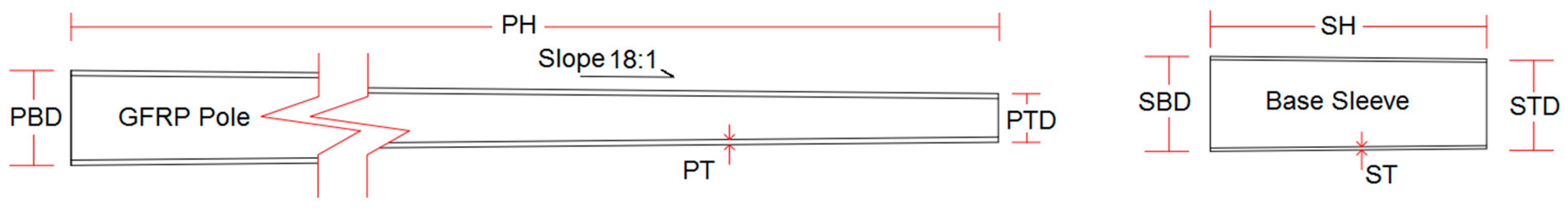
2.1. Geometry and Material Properties of the Tested Specimens

Each specimen consisted of three main parts: a GFRP hollow circular tapered pole, steel sleeve, and steel base plate, as illustrated in Figure 1 and Figure 2. The GFRP poles were fabricated using a tapered mold with a wall slope of 18 mm/m through the centrifugal casting process. Standard electrical glass fibers known as E-glass fibers and isophthalic polyester resin “Number 90” were used in the manufacturing process. The handle opening door was operated in the GFRP pole for electric maintenance purposes. The steel sleeves were fabricated as a hollow circular tapered section with the same wall slope of the GFRP pole (18 mm/m) to be inserted as the seat part of the GFRP pole and rejoined together by polyester resin. Each steel sleeve was welded to a rectangular steel base plate using a fillet weld. The base plate was fixed to a concrete base by four anchor bolts with a diameter of 28 mm, an embedment length of 600 mm, and end hooks to resist the splitting from concrete. Moreover, a handle door was fabricated and located on the compression side of the tested pole. Different parameters were investigated experimentally. These parameters included the pole wall and steel sleeve thicknesses, total length of the pole and steel sleeve, the top and bottom diameters of poles, the top and bottom diameters of the steel sleeve, and base plate dimensions. Table 1 presents the geometric configurations of each tested specimen. The mechanical and physical properties that were used for the E-glass fiber of poles, isophthalic polyester resin, and steel parts are listed in Table 2 and Table 3.

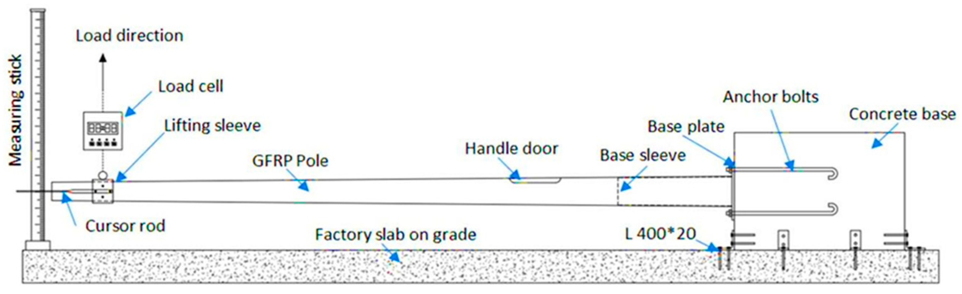
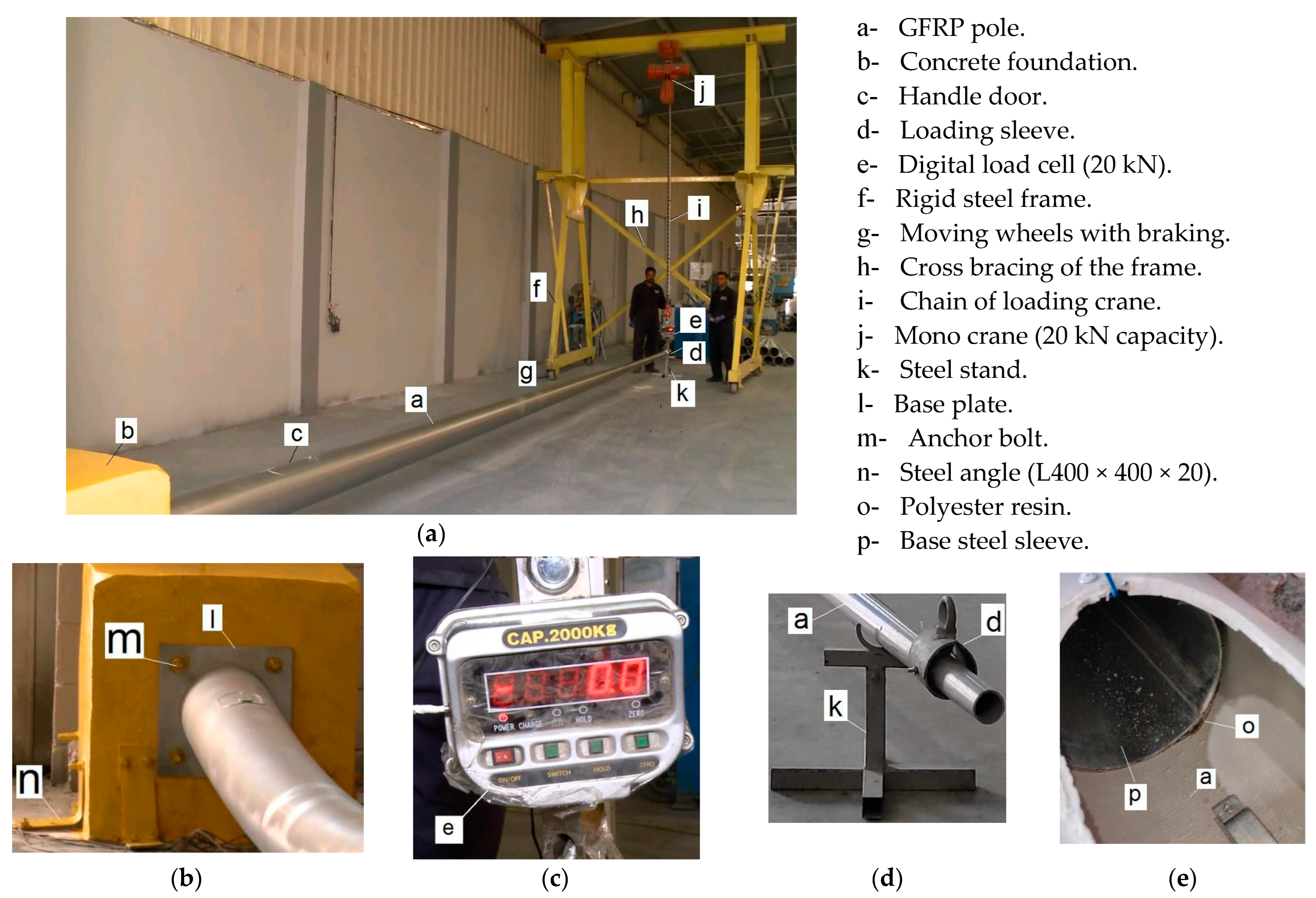
2.2. Test Setup and Instrumentation

The mechanical cantilever bending test setup was prepared and fabricated according to the specifications and recommendations of the standard ASTM D 4923 [24], as shown in Figure 2 and Figure 3. Plain concrete footings with a 28-day compressive strength of 25 MPa and a square cross-section of 800 mm × 800 mm side lengths and 1000 mm height was used as the fixed support for the tested poles. The concrete foundation was fixed to the ground by using anchored steel angles (L400 × 20 mm) to prevent any rotations or translations during the test (see Figure 3b). A lifting crane system was used as the loading system to apply the lateral load to the pole. The crane system consisted of an electrical mono crane with a capacity of 20 kN mounted on a movable steel crane bridge. To avoid any lateral sway during loading, the crane bridge was designed as a rigid steel frame, which consisted of cross bracing and wheels with a braking system to be suitable for many different pole lengths. A lifting sleeve was attached to the tested pole at a distance of 300 mm from the top to distribute the applied load on the pole surface. The crane bridge and its hook were centered above the lifting sleeve and connected with the lifting sleeve via a digital load cell to monitor the applied load during the test (Figure 3c). The tested pole was adjusted horizontally before loading by a steel stand and water balance to ensure the perpendicularity of the pole center line and the measuring stick.
The load was applied incrementally by lifting the crane with a rate of 0.3 mm/s until the failure occurred. The displacement at the top of the tested pole was measured by using a steel thin cursor rod that refers to a measuring stick that has a 3.0 m height, which was divided into millimeters (see Figure 2).

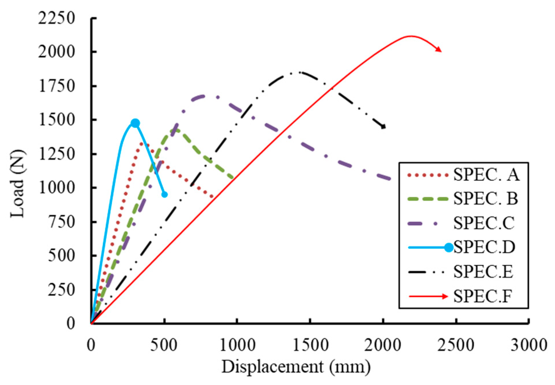
3. Experimental Results and Observations

Figure 4 shows the deformed shape of one of the tested specimens. A high flexibility behavior of the GFRP pole and then plastic behavior was observed when plastic hinges started to form at the handle door position of the poles. Subsequently, local buckling failure at the handle door position occurred for all specimens. Moreover, yielding was observed at the tension region of the base plate with a thickness of 10 mm. The results of both of the load–displacement curves and statistical values of toughness for all of the tested GFRP poles are shown in Figure 5 and Figure 6. The load–displacement curves exhibited a severe upward trend in the load progress until the specimens buckled and the failure occurred. The deformation and toughness results showed that the pole with the largest height (SPC.F) was more flexible than the other poles. The pole (SPC.C) also had a significant toughness because the base sleeve height allowed the pole to deform more easily.

4. Finite Element Analysis

Abaqus software [31] was employed to develop a three-dimensional nonlinear finite element (FE) model to include all of the nodes, elements, material characteristics, dimensions, boundary conditions, and loads into an effective technique of analysis. The developed FE model was used as an economic alternative tool instead of expensive experiments. Therefore, it was used to investigate the effect of a wide variety of parameters on enhancing the toughness of the GFRP poles.

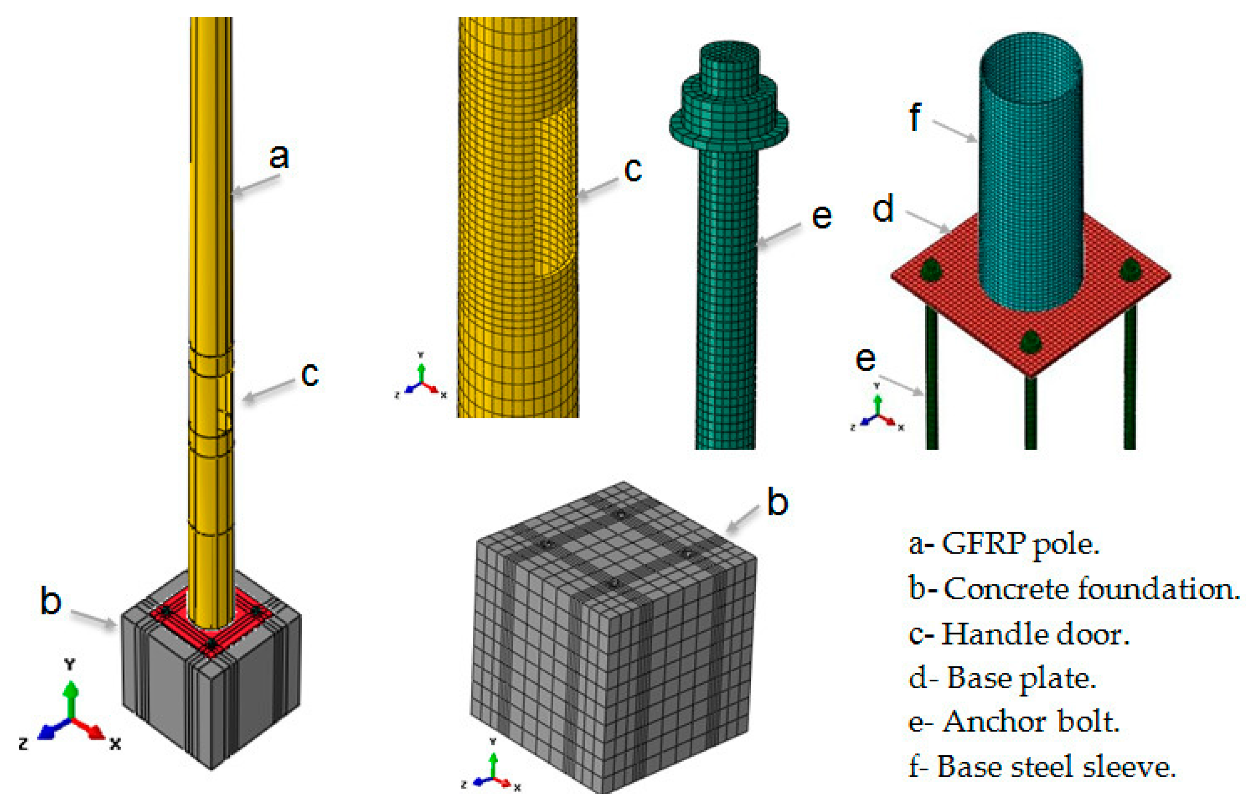
4.1. Elements Types, Meshing, and Material Modeling

A three-dimensional eight-nodded quadrilateral solid element (C3D8R) with a reduced integration algorithm was used to model the GFRP pole, steel sleeve, base plate, anchor bolts, and concrete foundation. The conical shape of the poles and steel sleeves were created by revolution and extruding the section with different diameters at the ends. The holes of the anchors’ bolts and electric cable entrances were modeled by creating circular holes in the concrete foundation and GFRP pole, while the type of suitable elements that were used in the conical GFRP pole, steel sleeve, and epoxy resin was the eight-node quadrilateral solid element (Q8) with a reduced integration algorithm. This element has curved sides to be able to study the effect of a thick layer of epoxy resin between the steel sleeve and GFRP pole. Figure 7 shows the FE configuration of the cantilever bending test of the GFRP pole.
A mesh sensitivity study was performed on three element sizes of 5 mm, 10 mm, and 20 mm to obtain accurate results with an optimal computational time of analysis. The component of the FE model was meshed with different divisions. To satisfy the convergence requirements, the mesh size of 10 mm was used for the first bottom part of the GFRP pole until 1.0 m after the handle door position whereas the mesh size of the remaining part of the GFRP pole and concrete foundation was taken as 20 mm. Moreover, the mesh around the holes of the anchor bolts and cable holes was refined.
Bi-linear relationships were used to model the stress–strain relationship of the steel reinforcement. The modulus of elasticity and yielding stress were used to define the linear elastic part. Otherwise, the ultimate stress and plastic strain were used to define the strain hardening part. On the other hand, a linear relationship was adopted in this study to model the stress–strain relationship of GFRP. The equivalent modulus of elasticity and ultimate stress were used to define this relationship. The mechanical and physical properties that were used for the E-glass fiber of poles, the isophthalic polyester resin, and steel parts, are listed in Table 2 and Table 3. For concrete material, the behavior was defined by the compressive strength, tensile strength, and modulus of elasticity to consider the concrete cracking and crushing.

4.2. Interaction Properties

Each component of the FE model was connected by appropriate interaction properties. To distribute the load acting on the whole cross-section, tie constraints of the reference point with a surface of the cross-section were assigned by rigid body tie formulation. Master and slave surface contact was assigned to simulate the contact of the epoxy resin between the internal surface of the conical steel sleeve and the external surface of the conical GFRP pole. Moreover, the contact between the bolt head and washer, bolt shank, and the holes of the base plate, washer, and the base plate, and base plate and foundation were assigned by surface-to-surface contact. The tangential and normal behavior of the surface-to-surface contact were simulated by penalty friction formulation with a value of 0.2 as a friction coefficient. The tie constraint was employed to connect each of the base sleeves with the base plate and the anchor bolt’s shank with the concrete foundation.

4.3. Loading and Boundary Conditions

The applied load was simulated by defining a lateral displacement over the lifting sleeve area at 300 mm from the end of the pole. To permit the occurrence of a small angle of deformation at the base plate, fixed boundary conditions were applied to the nodes of the external sides of the foundation to simulate the fixation between the concrete footing and the ground and the softening of the base plate. The translations and rotations in the X-, Y-, and Z-directions were constrained. The output reaction of the boundary conditions was used to develop the load–deflection curves of the analyzed GFRP poles.

4.4. Failure Criterion

According to AASHTO [32], the structural design of the GFRP lighting pole is performed based on the allowable stress method to support an equivalent point load (Pe), which was applied at 300 mm from the top. Therefore, the failure criterion of the pole was determined by sustaining a maximum point load of 2Pe or a maximum top displacement not greater than 15% of the pole height. The FE analysis was terminated when one of these criteria was approached.

4.5. FE Validations and Discussions

The numerical simulation results were compared to the experimental results to verify the reliability of the developed FE model to simulate the static response of the GFRP poles. The FE verifications showed reasonable predictions of the load–displacement relationships as well as the peak loads, as shown in Figure 8. Moreover, the same mode of failure was obtained numerically and experimentally, which was local buckling at the handle door, as shown in Figure 9. More perceptive verifications between the experimental and the FE results are provided in Table 4. The FE predictions of the failure load were generally 1.98–3.15% higher than the test values, while the maximum displacements ranged from 1.11% to 3.52% higher than the experimental results. These results indicate that there is a strong correlation between the FE and experimental results. Therefore, the developed FE model was used to run additional investigations on other parameters to evaluate the effect of various properties on the overall structural response of the GFRP pole.

5. Parametric Study

An extensive parametric study was performed using the verified FE model to obtain the most effective properties that increase the pole toughness. The investigated parameters included the geometric characteristics, GFRP pole wall thickness (PT), base plate dimensions (L and B), base plate thickness (T), electric cable hole diameter (HD), base plate material properties (SG), base sleeve height (SH), and base sleeve thickness (ST) (see Figure 1). Two lengths of 6 m and 10 m were analyzed based on the widest spread poles in both the urban and rural roads. Each analyzed pole was labeled with a unique name (pole group—pole thickness—base sleeve height—base sleeve thickness—base plate dimensions—base plate thickness –diameter of electric cable hole—base plate steel grade) to cover all of the studied parameters. Table 5 lists a summary of the geometric properties and toughness of the analyzed GFRP poles. The area under the load–deflection curve was used to express the GFRP pole toughness.

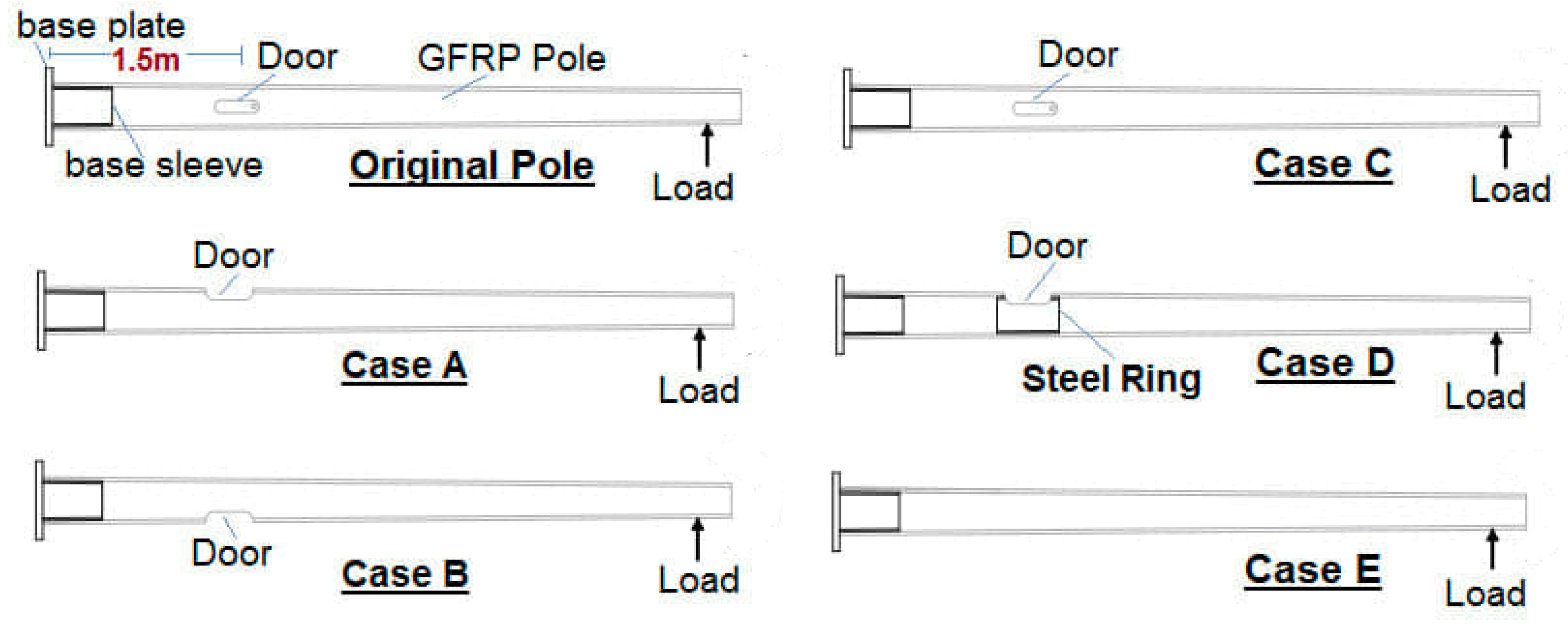
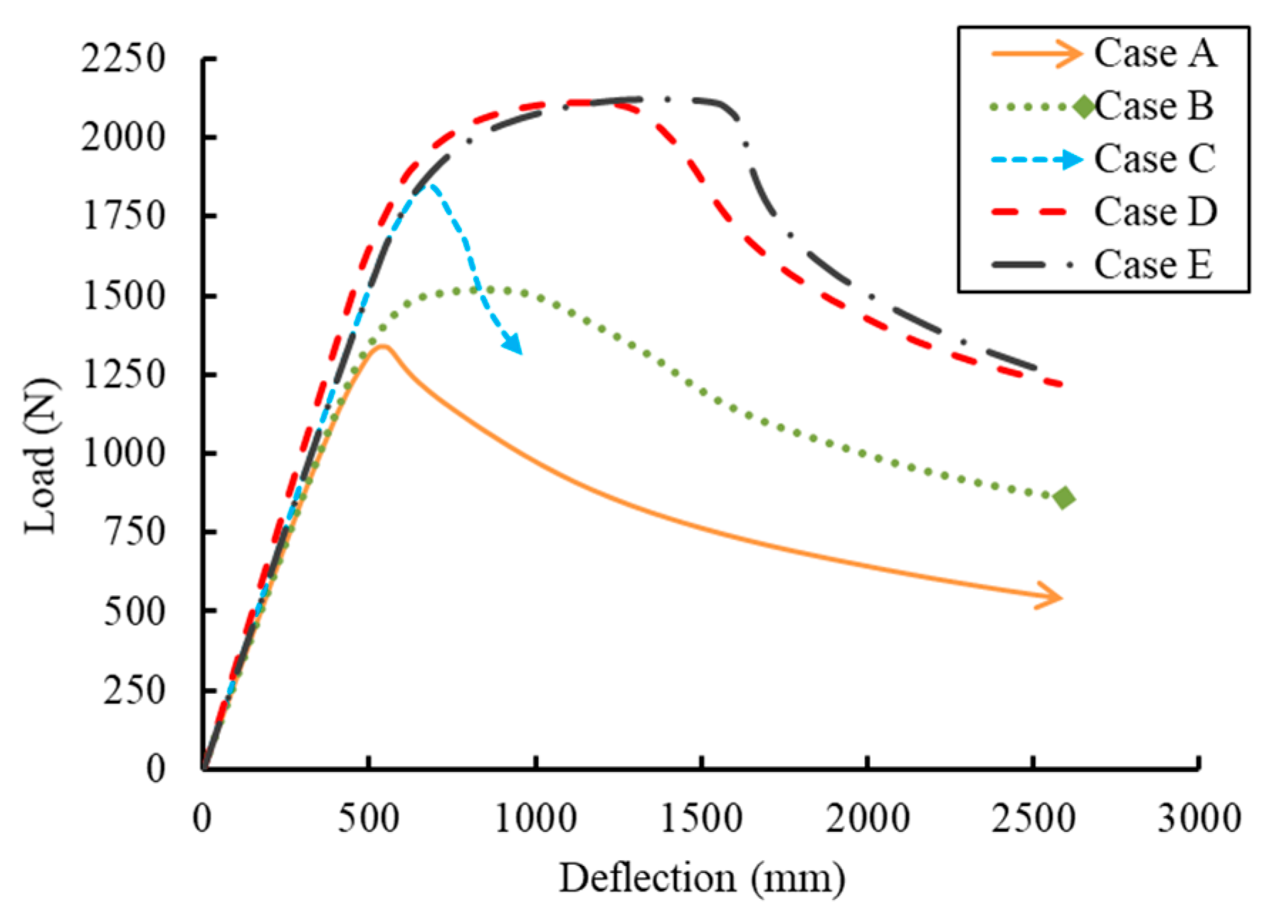
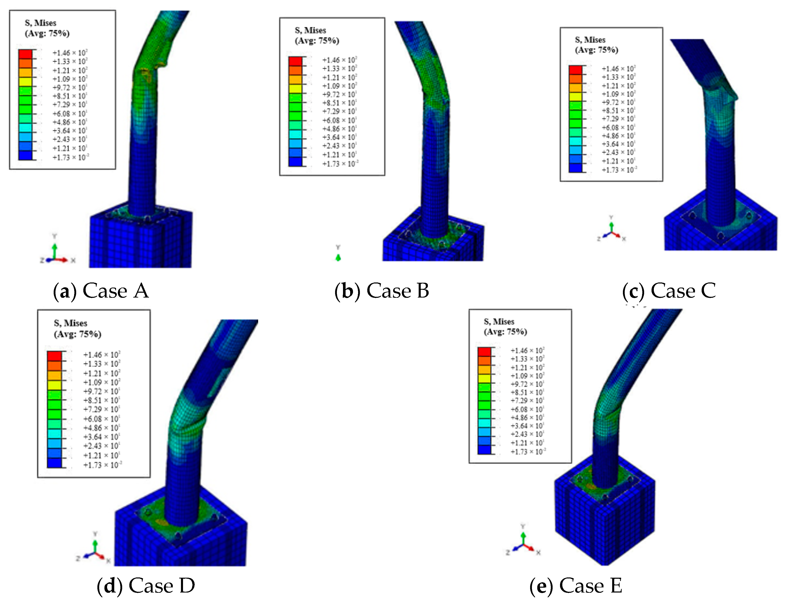
5.1. Effect of the Handle Door Opening Position

The effect of the position of the electric handle door was investigated in this section. Five cases were analyzed as follows (see Figure 10). Case A: the handle door was on the compression side of the pole; Case B: the handle door was on the tension side of the pole; Case C: the handle door was on a 90 degrees of the tension and compression sides; case D: the handle door was removed (without a handle door); and case E: the handle door was on the compression side and was strengthened with a steel ring. Figure 11 presents the load–deflection relationships of the analyzed poles with different positions of the electric handle door. The stiffness of the analyzed poles was the same until failure. These deformation relationships confirmed that the weakest scenario was case A, where the handle door was located on the compression side of the pole. Local buckling at the handle door was the mode of failure, which controlled the bending behavior of the GFRP poles as shown in Figure 12a. However, the two cases of no and strengthened handle doors (cases D and E) showed a similar behavior and peak load. The mode of failure in these two cases was also local buckling, but above the position of the handle door, as shown in Figure 12d,e.
These comparisons confirmed that the steel ring in case E, as a strengthening technique for the handle door, eliminated the weakness in the GFRP pole due to the existence of the handle door. Strengthening the handle door increased the ultimate capacity of the GFRP pole and prevented the fracture of this region. Moreover, the base system became the most effective for pole deformation. Therefore, the door opening effect was neglected and case D was considered in the remaining parametric study to explore the base system of this kind of pole.

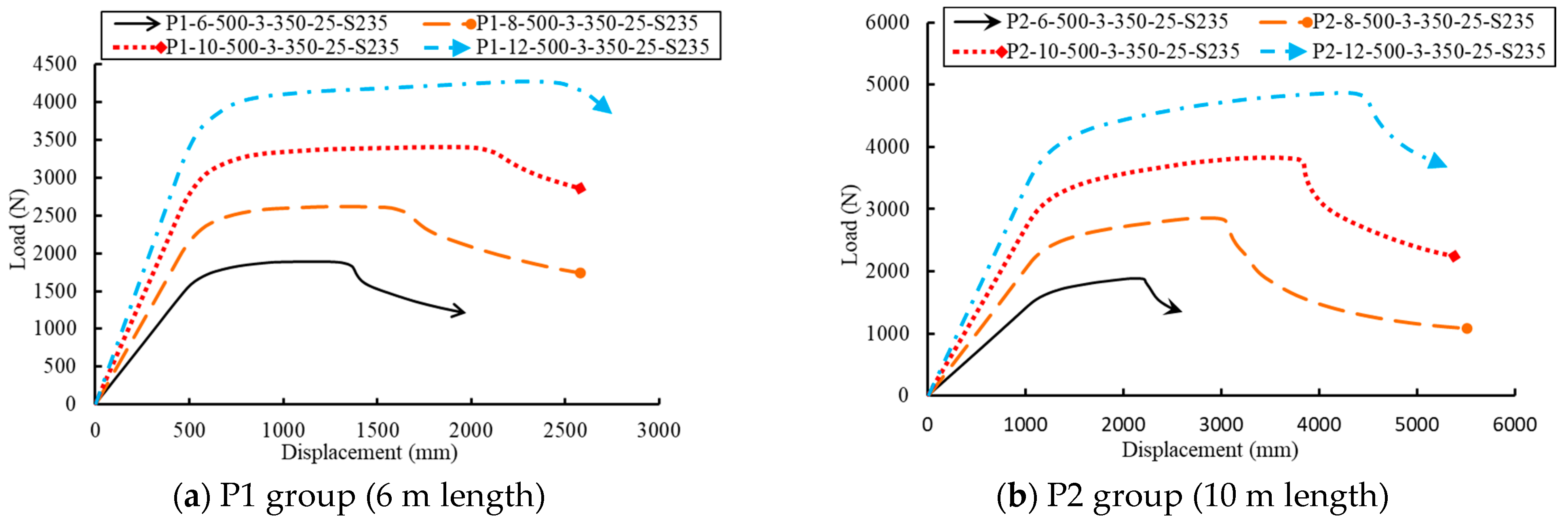
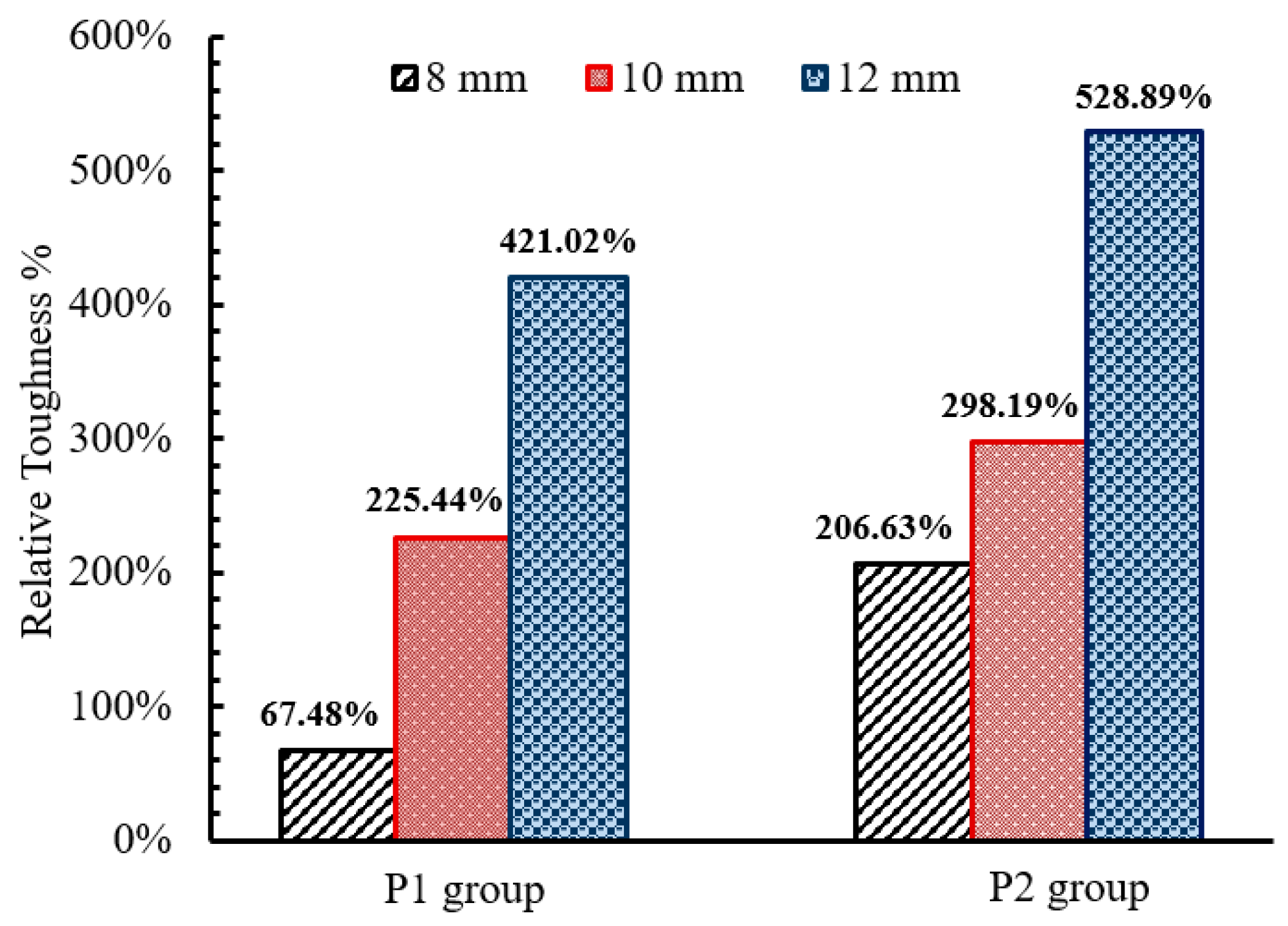
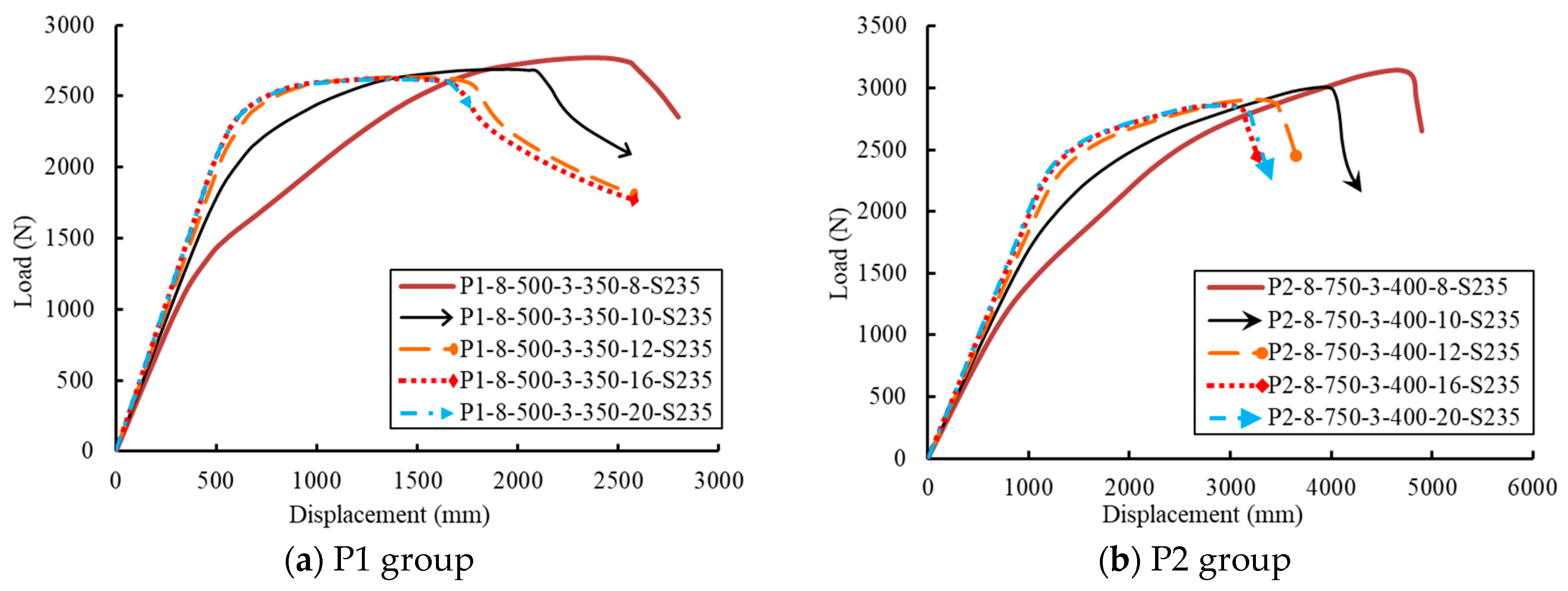
5.2. Effect of the GFRP Pole Wall Thickness (PT)

The effect of the GFRP pole wall thickness was investigated by modeling eight tapered GFRP poles with different wall thicknesses (6 mm, 8 mm, 10 mm, and 12 mm), as listed in Table 5. All other geometric and material properties were kept the same as the reference properties. Figure 13 shows the effect of the GFRP pole wall thickness through the load–displacement curves for each group. The results confirmed that the wall thickness provided significant improvements in the flexural stiffness and the ultimate strength of the GFRP pole. Therefore, the area under the load–deflection curve increased and subsequently enhanced the GFRP pole toughness. Figure 14 illustrates the effect of the GFRP pole wall thickness on the normalized toughness. The enhancements were addressed relative to the wall thickness of 6 mm. Increasing the pole wall thickness from 6 mm to 12 mm exhibited significant ductility where the normalized toughness percentage increased up to 421% and 529% for the first and second groups, respectively. According to Figure 14, the normalized toughness of the GFRP poles in the second group was higher than that of the poles in the first group because the longer height of the poles gave more displacement; besides, the wider cross-section of the second group gave a higher load capacity. The flexibility of the GFRP poles was directly proportional to their length.

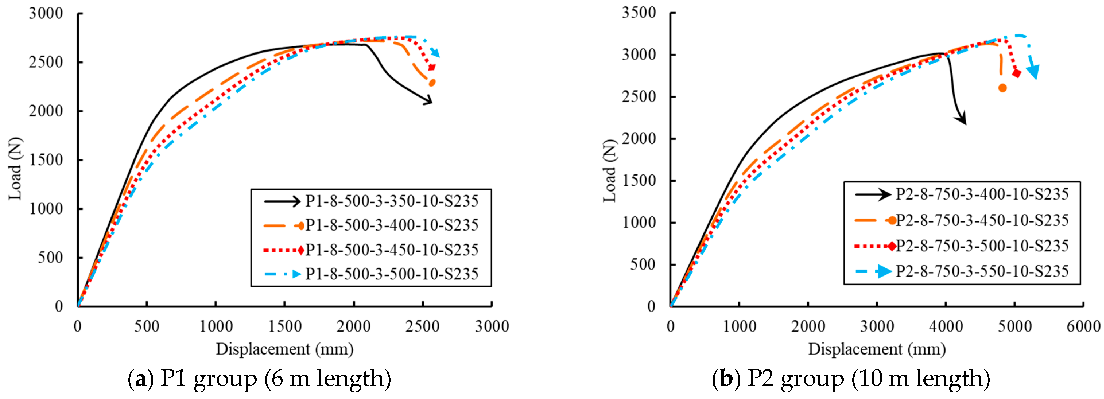
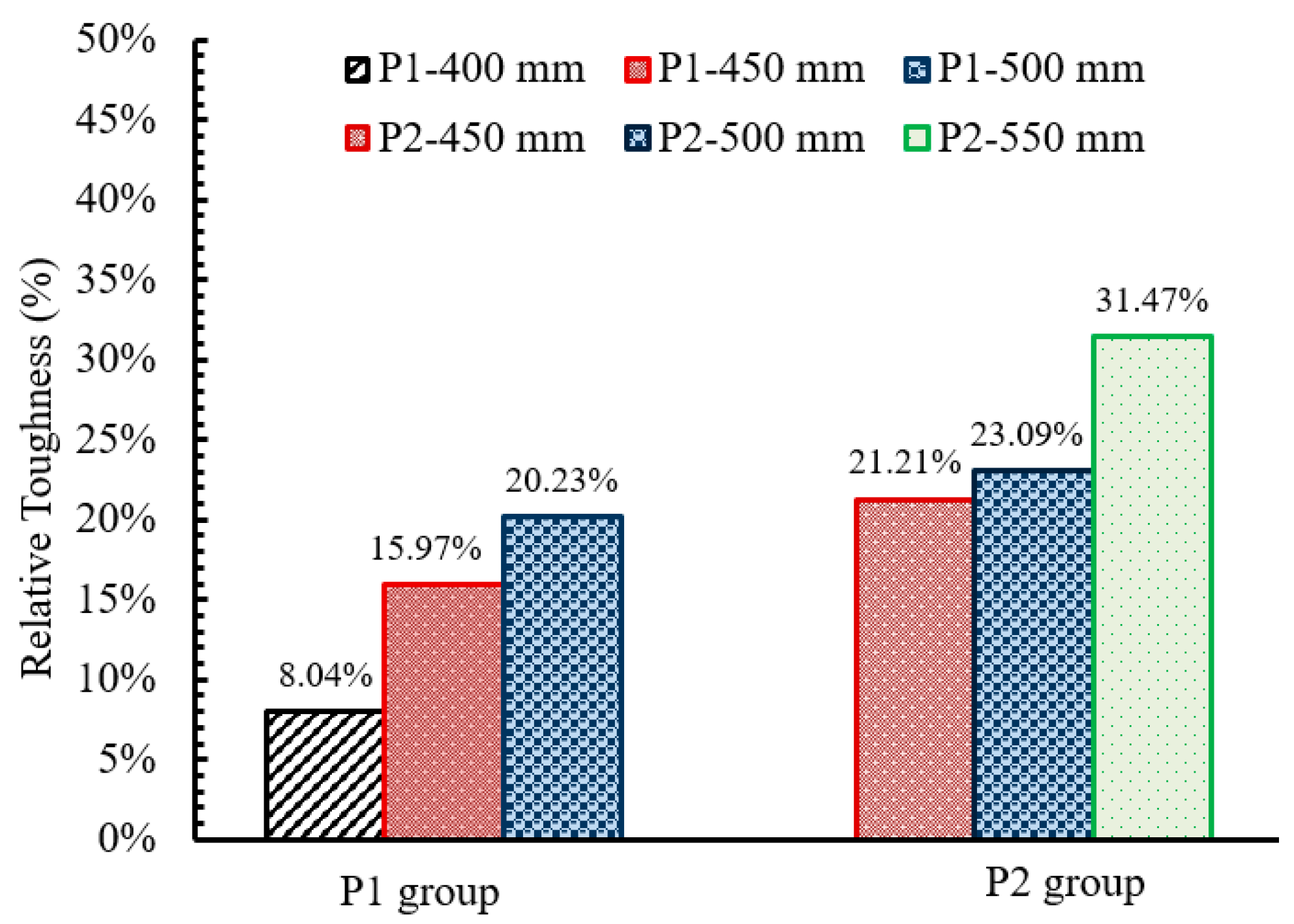
5.3. Effect of the Base Plate Dimensions (L and B)

The base plate dimensions (L and B) varied among the values of 350 mm, 400 mm, 450 mm, 500 mm, and 550 mm, as listed in Table 5. The von Mises stress for the deformed base plates of 350 mm and 500 mm of the GFRP poles with a 6 m length are shown in Figure 15. Increasing the base plate dimension helps the pole to deform plastically between the two tension anchor bolts at the tension side. Figure 16 emphasizes this behavior through the deformation curves. However, increasing the base plate dimensions decreased the pole stiffness, whereas the toughness and capacity of the GFRP poles were promoted as the base dimensions increased.
The normalized toughness in Figure 17 was determined for each studied group relative to the base plate dimensions of 350 mm and 400 mm for the first and second groups, respectively. Increasing the base plate dimensions provided significant improvements in ductility because the normalized toughness percentage increased up to 20% and 31.5% approximately when the base plate dimensions increased to 500 mm and 550 mm in the first and second groups, respectively.

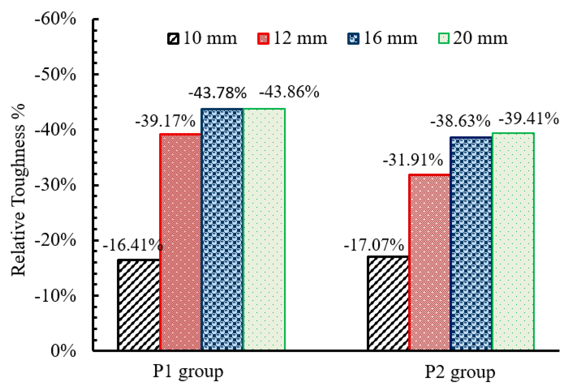
5.4. Effect of the Base Plate Thickness (T)

The base plate thicknesses of 8 mm, 10 mm, 12 mm, 16 mm, and 20 mm were investigated by modeling ten tapered GFRP poles with the two lengths of 6 m and 10 m. Figure 18 shows the effect of the base plate thickness on the load–displacement relationships. Increasing the base plate thickness reversely affects the deformation capacity and energy absorption before fracture. The thinnest base plate thickness exhibited high deformations and increased the overall pole toughness. Figure 19 illustrates the normalized toughness of the GFRP poles with different base plate thicknesses relative to the thickness of 8 mm for each group. A significant reduction in the normalized toughness was obtained when the base plate thickness increased from 10 mm to 16 mm. Moreover, a slight reduction was observed when the base plate thickness increased to 20 mm.

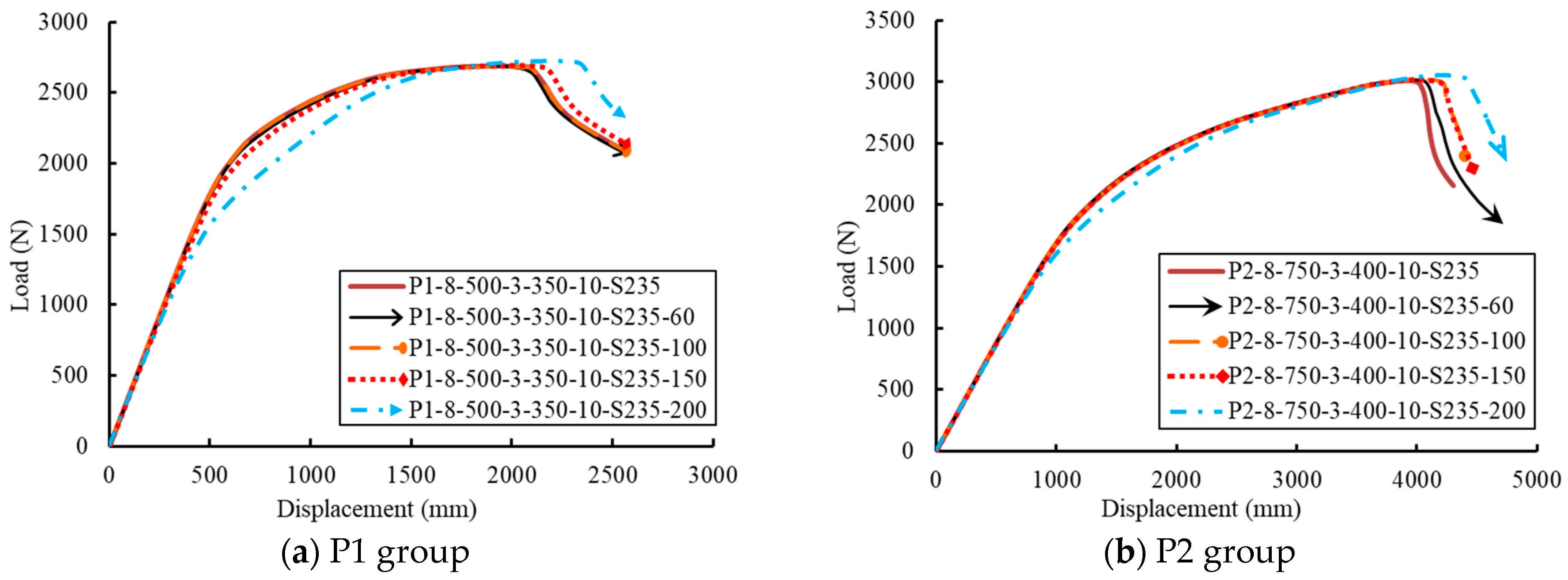
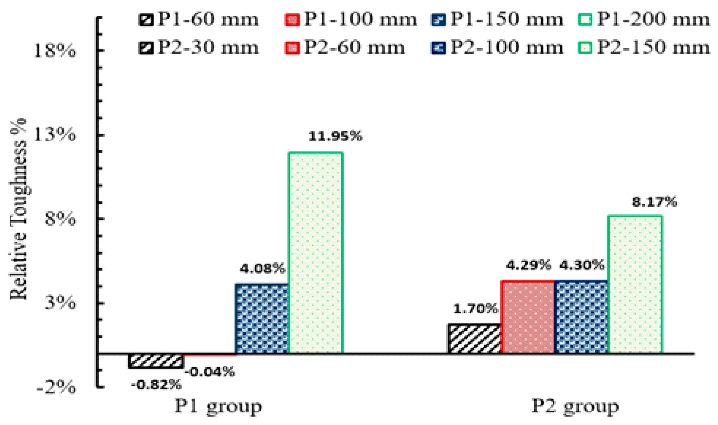
5.5. Effect of the Electric Cable Hole Diameter (HD)

The effect of the diameter of the electric cable hole was investigated through the values of 60 mm, 100 mm, 150 mm, and 200 mm. The diameter of the electric cable hole exhibited a slight effect on the deformation of the pole. However, higher deformation and smaller stiffness were observed when the diameter of the hole became 200 mm, as shown in Figure 20. The normalized toughness of the GFRP poles with different hole diameters is illustrated in Figure 21 relative to the toughness of the GFRP poles without an electric cable hole. The electric cable hole diameter provided significant improvements in the normalized toughness percentage, which increased by 12% and 8.2% when the diameter increased to 200 mm and 150 mm in the first and second groups, respectively.

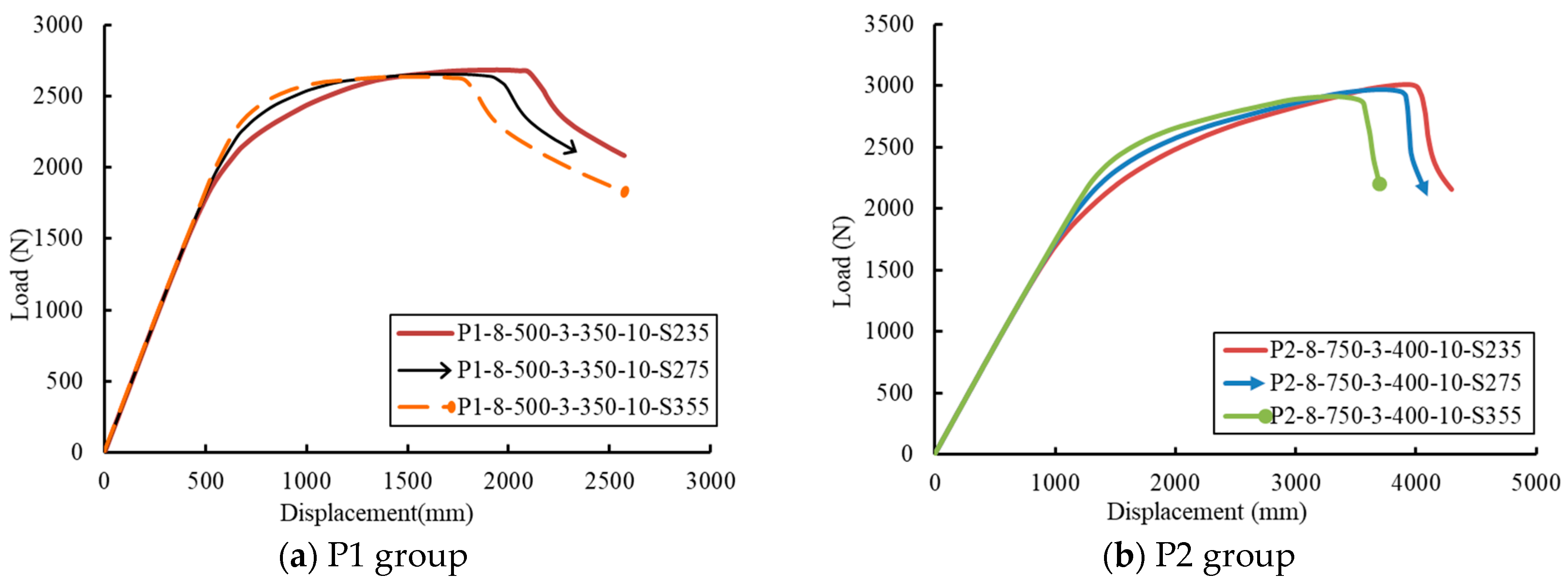
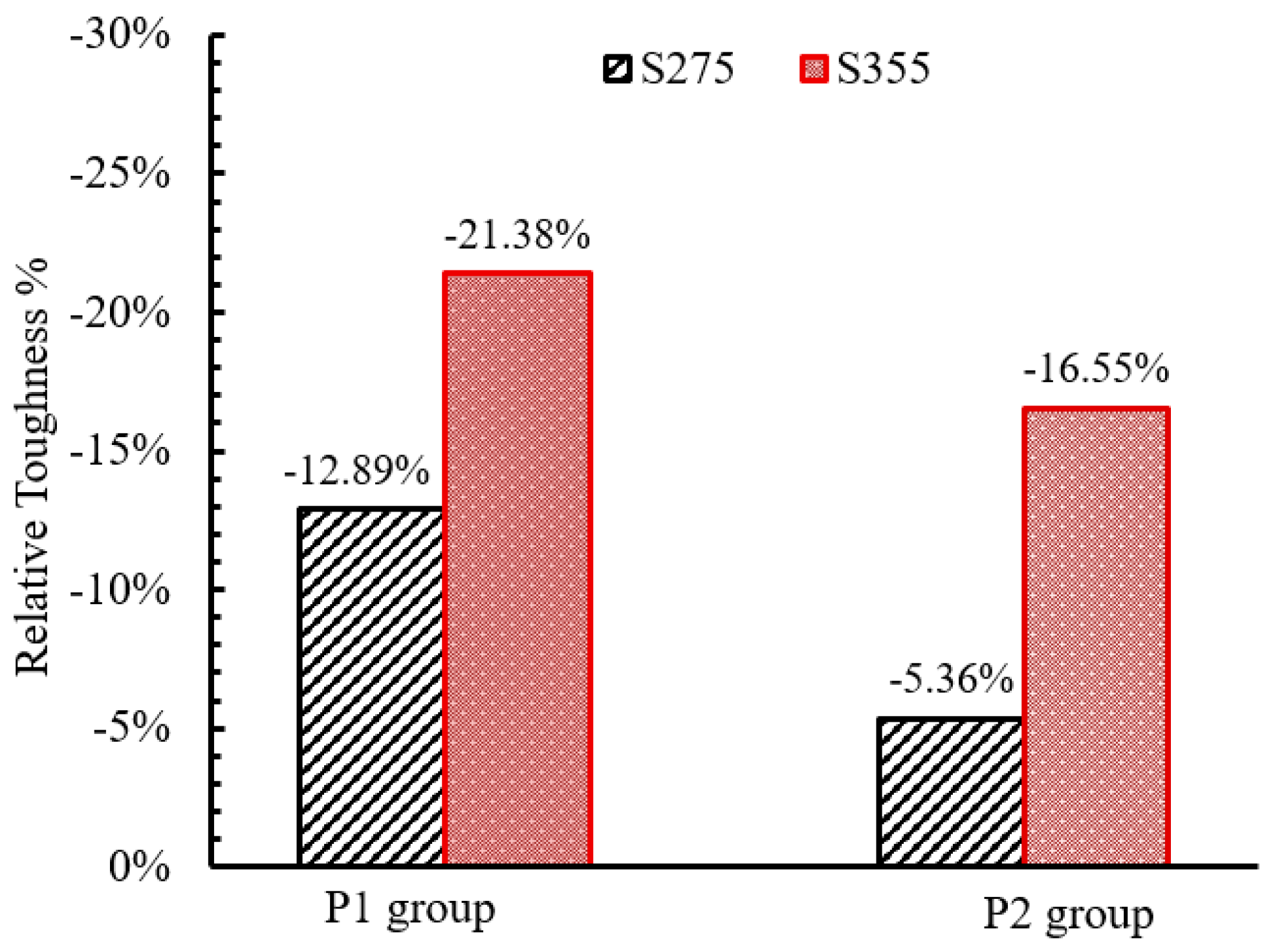
5.6. Effect of the Base Plate Material Properties (SG)

The steel grade of the base plate was explored by investigating the S235, S275, and S355 grades (European structural steel grade), as listed in Table 5. By changing the steel grade of the base plate from mild to high-strength steel, the same stiffness was exhibited. However, the mild steel showed higher capacity and ductility (see Figure 22). The normalized toughness of the analyzed GFRP poles with different base plate material properties is shown in Figure 23 relative to the toughness of the GFRP poles with the S235 grade. Significant reductions in the normalized toughness of 21% and 16.5% were obtained when the steel grade S355 was used for the first and second groups, respectively.

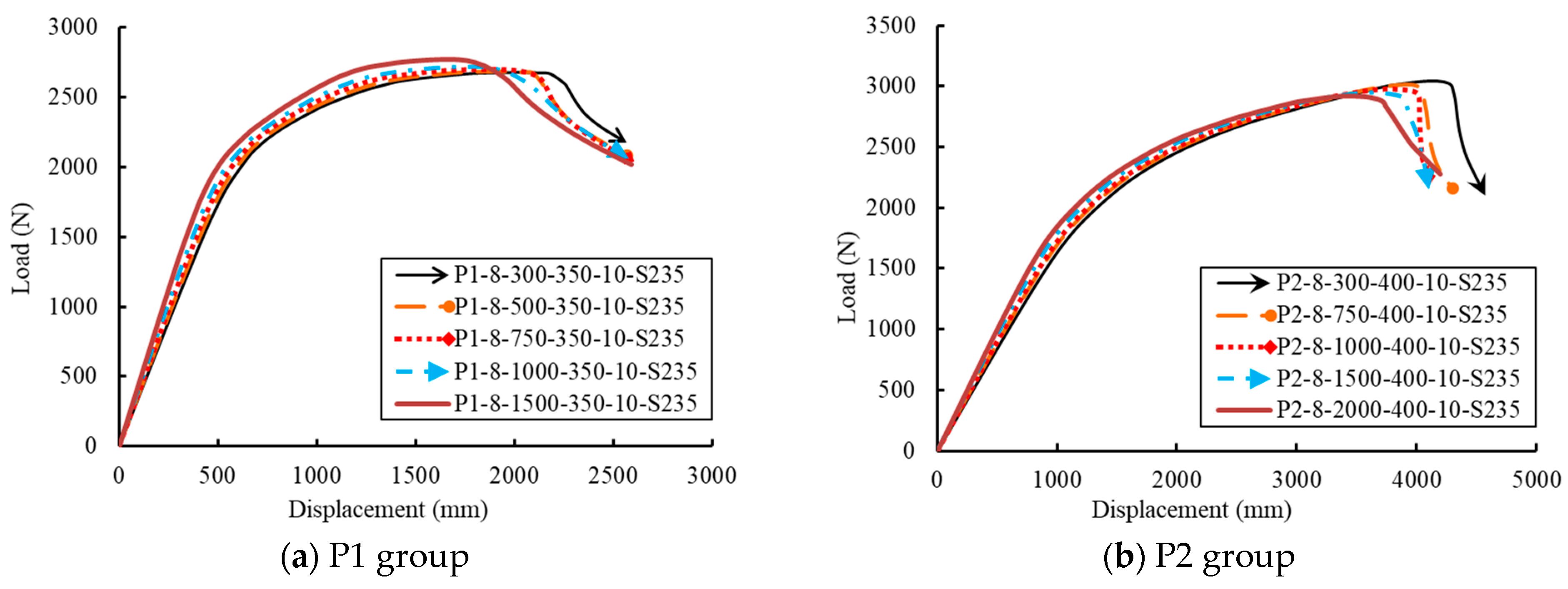
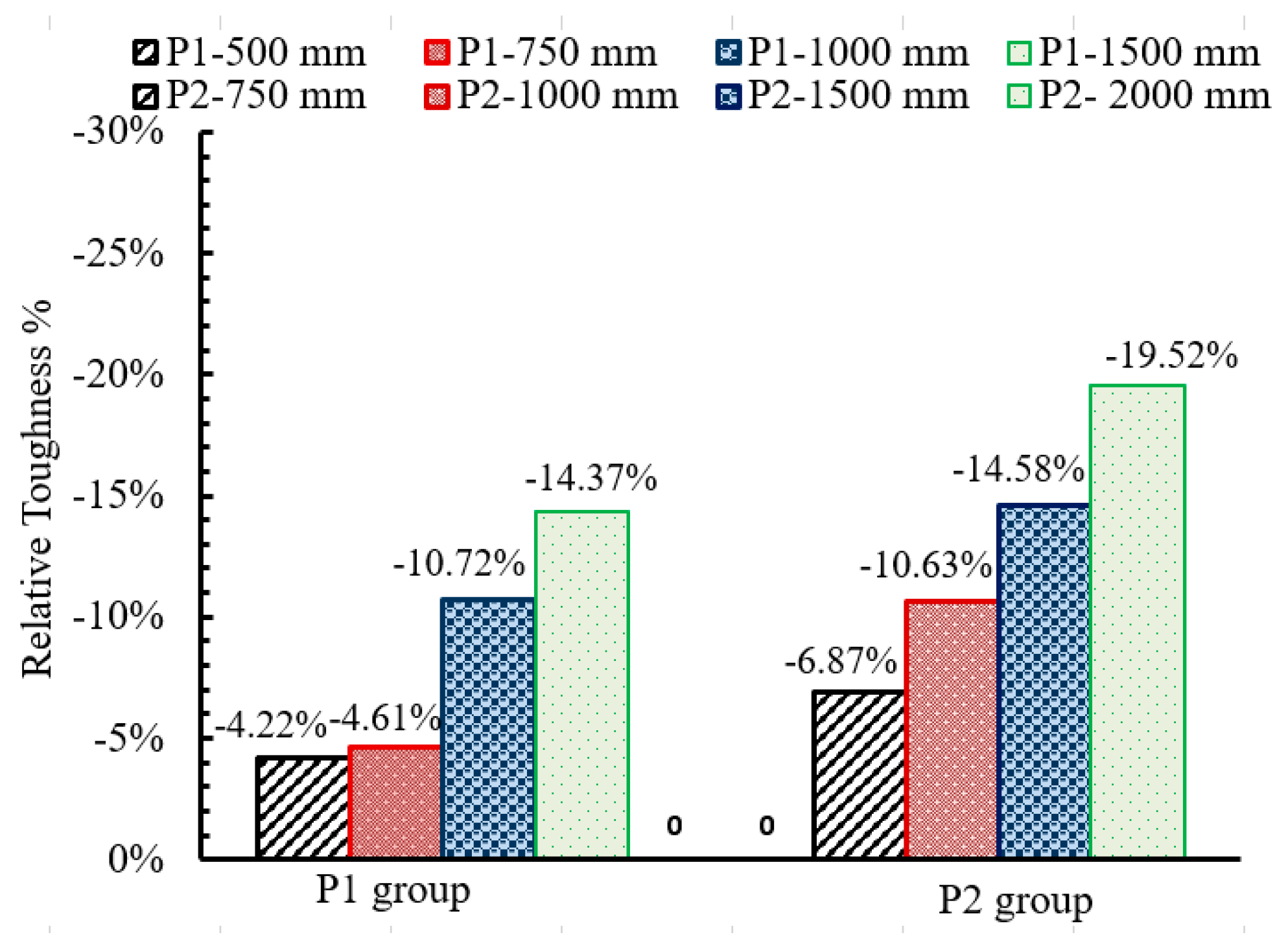
5.7. Effect of the Base Sleeve Height (SH)

The height of the base sleeve was investigated by modeling ten tapered GFRP poles, as listed in Table 5. A slight effect on the stiffness and ductility was exhibited by changing the base sleeve height (see Figure 24). Using a smaller height of 300 mm showed the highest deformation and capacity and increased the overall pole toughness. Increasing the base sleeve height prevented the pole rotation about its support. Figure 25 illustrates the normalized toughness of the analyzed GFRP poles relative to the toughness of the GFRP poles with a sleeve height of 300 mm. Increasing the base sleeve height caused significant reductions in the normalized toughness. These reductions were 14% and 19.5% approximately when the base sleeve heights increased to 1500 mm and 2000 mm for the first and second groups, respectively.

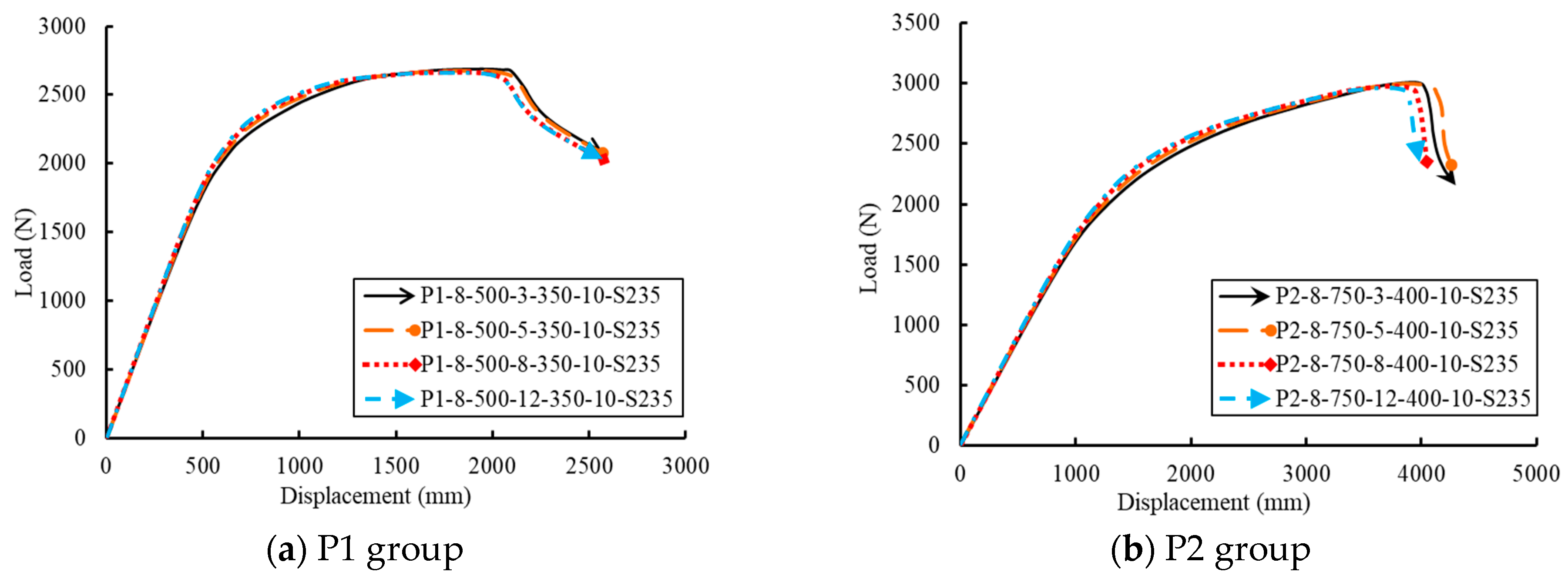
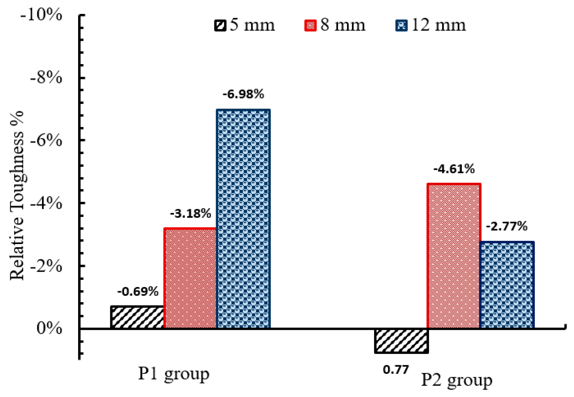
5.8. Effect of the Base Sleeve Thickness (ST)

The base sleeve thicknesses of 3 mm, 5 mm, 8 mm, and 12 mm were investigated in this study (Table 5). The thickness of the base sleeve did not affect the first group of GFRP poles with a 6.0 m length, as shown in Figure 26a. However, the thickness caused a slight effect on the deformation of the second group with a length of 10.0 m. Therefore, this parameter could become effective in the longer GFRP poles. Figure 27 emphasizes this small effect through the normalized toughness of the GFRP poles with different base sleeve thicknesses relative to the thickness of 3 mm for each group.

6. Significance of the Research

The purpose of this article is to promote the effect of the base steel sleeve on the flexural response and toughness of the lighting GFRP poles. Strengthening the handle door was investigated to eliminate the weakness in the GFRP pole. The experimental tests were followed by parametric studies to investigate the effect of GFRP pole wall thickness, base plate dimensions, base plate thickness, electric cable hole diameter, base plate material, base sleeve height, and base sleeve thickness on the ductility response of GFRP pole.

7. Conclusions

Six full-scale cantilever bending tests were carried out and used to verify a developed numerical simulation using Abaqus. An extensive parametric study was conducted to investigate the effects of the influential geometric parameters. The experimental and numerical studies came to the following conclusions:
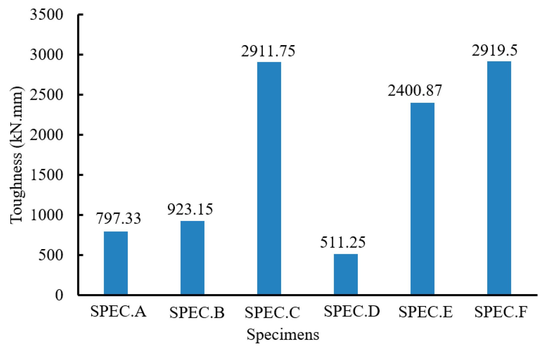
  • By increasing the pole’s height by two times, the toughness was promoted at least three and half times approximately.
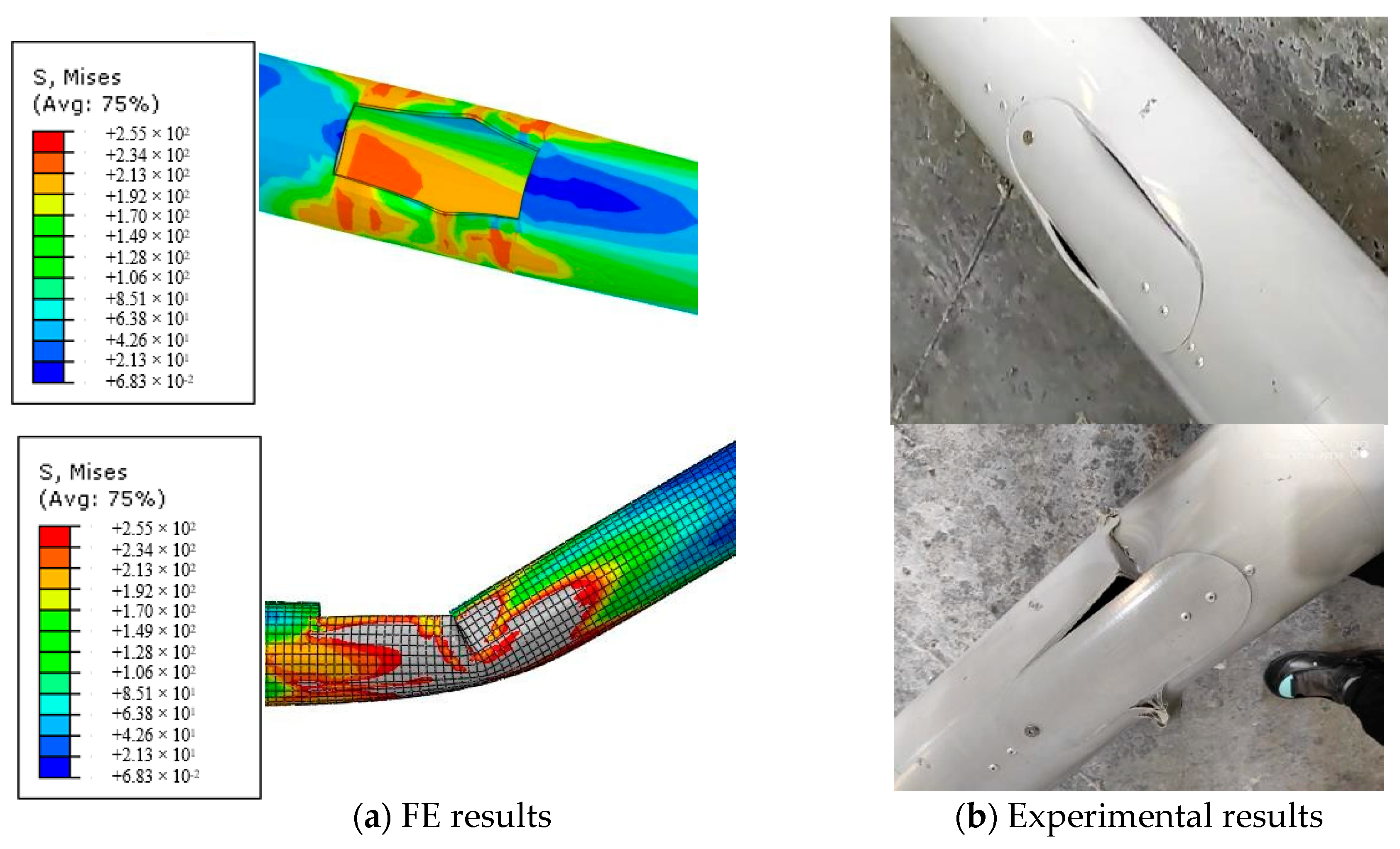
  • The dominant failure mode of the GFRP pole with an anchored base system was local buckling around the handle door.
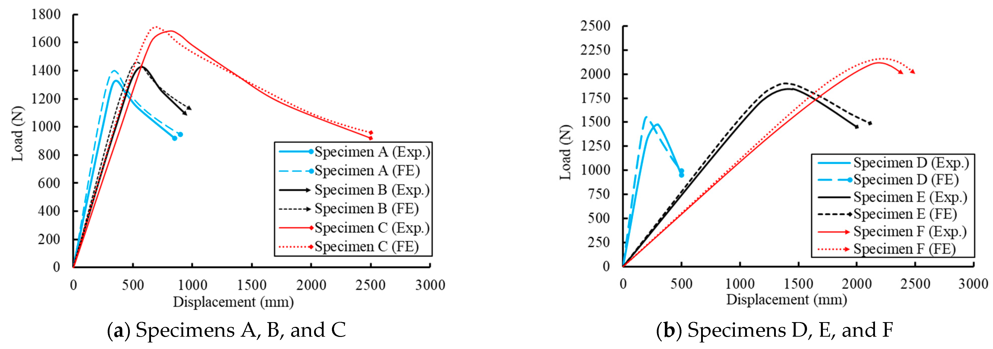
  • The FE predictions of the load–displacement curves relative to the experimental results were generally by values less than 3.5% approximately.
  • Strengthening the handle door with a steel ring increased the ultimate capacity of the GFRP pole and prevented the fracture of this region. Moreover, the base system became the most effective for pole deformation.
  • The wall thickness of the GFRP pole had the most effective parameter that affected the ductility and toughness of the GFRP pole, while the base sleeve thickness had a slight effect.
  • Using mild steel for the base plate promoted the toughness of the GFRP pole.
  • Increasing the thickness of the base plate had a reverse effect on the ductility and toughness of the GFRP pole, while the base sleeve thickness had a slight direct effect.
Future investigations are recommended to study the development of more reliable methods using full-scale static test specimens by strengthening the handle door using steel rings. Furthermore, the simulation of car collisions against GFRP poles can be evaluated numerically. Moreover, the failure criteria of both base sleeve and embedded base due to vehicle collisions will be evaluated.

Author Contributions

Conceptualization, M.T.N. and O.E.; Methodology, M.T.N.; Software, M.E.K. and I.T.A.; Validation, M.E.K. and I.T.A.; Formal analysis, A.E.-Z.; Investigation, M.E.K. and I.T.A.; Resources, M.T.N.; Data curation, A.E.-Z.; Writing—original draft preparation, M.E.K., I.T.A. and M.T.N.; Writing—review and editing, A.E.-Z.; Visualization, A.E.-Z.; Supervision, O.E. and M.T.N. All authors have read and agreed to the published version of the manuscript.

Funding

This research received no external funding.

Institutional Review Board Statement

Not applicable.

Informed Consent Statement

Not applicable.

Data Availability Statement

Not applicable.

Acknowledgments

The support from Elsewedy Electric is acknowledged. We also greatly acknowledge the industry support and thank the technicians at the Egy Plast Elsewedy Poles Factory for their assistance in conducting relevant experiments.

Conflicts of Interest

The authors declare no conflict of interest.

References

  1. Elmarakbi, A.; Fielding, N. A new design of roadside pole structure: Crash analysis of different longitudinal tubes using LS-DYNA. In Proceedings of the 7th European LS-DYNA Conference 2009, Salzburg, Austria, 14–15 May 2009. [Google Scholar]
  2. Bondok, D.H.; Salim, H.A. Numerical Modeling of Conventional Steel Stud Walls Static Resistance for Blast Response Predictions. Struct. Eng. 2014, 140, 04014035. [Google Scholar] [CrossRef]
  3. Nawar, M.T.; Arafa, I.T.; Elhosseiny, O.M.; El-Zohairy, A. Full static resistance of castellated steel beams with hexagonal web openings for blast response predictions. Eng. Struct. 2021, 245, 112844. [Google Scholar] [CrossRef]
  4. Verma, S.K.; Bhadauria, S.S.; Akhtar, S. Monitoring corrosion of steel bars in reinforced concrete structures. Sci. World J. 2014, 2014, 957904. [Google Scholar] [CrossRef] [Green Version]
  5. Mirsayapov, I.; Yakupov SHassoun, M. About concrete and reinforced concrete corrosion. IOP Conf. Ser. Mater. Sci. Eng. 2020, 890, 012061. [Google Scholar] [CrossRef]
  6. Polyzois, D.; Ibrahim, S.; Burachynsky, V.; Hassan, S.K. Glass fiber-reinforced plastic poles for transmission and distribution lines: An experimental investigation. In Proceedings of the 12th International Conference on Composite Materials, Paris, France, 5–9 July 1999; Available online: http://www.iccmcentral.org/Proceedings/ICCM12proceedings/site/papers/pap1201.pdf (accessed on 20 March 2022).
  7. Khayatazad, M.; De Pue, L.; De Waele, W. Detection of corrosion on steel structures using automated image processing. Dev. Built Environ. 2020, 3, 100022. [Google Scholar] [CrossRef]
  8. Ožbolt, J.; Balabanić, G.; Oršanić, F. Modelling corrosion of steel reinforcement in concrete. IOP Conf. Ser. Mater. Sci. Eng. 2019, 615, 012011. [Google Scholar] [CrossRef]
  9. Sathishkumar, T.P.; Satheeshkumar, S.; Naveen, J. Glass fiber-reinforced polymer composites—A review. Reinf. Plast. Compos. 2014, 33, 1258–1275. [Google Scholar] [CrossRef]
  10. Marzuki, H.F.A.; Jaafar, M. Laminate Design of Lightweight Glass Fiber Reinforced Epoxy Composite for Electrical Transmission Structure. Procedia Chem. 2016, 19, 871–878. [Google Scholar] [CrossRef]
  11. Farhangi, V.; Karakouzian, M. Effect of Fiber Reinforced Polymer Tubes Filled with Recycled Materials and Concrete on Structural Capacity of Pile Foundations. Appl. Sci. 2020, 10, 1554. [Google Scholar] [CrossRef] [Green Version]
  12. Gudonis, E.; Timinskas, E.; Gribniak, V.; Kaklauskas, G.; Arnautov, A.K.; Tamulėnas, V. FRP Reinforcement for Concrete Structures: State-of-the-Art Review of Application and Design. Eng. Struct. Technol. 2013, 5, 147–158. [Google Scholar] [CrossRef]
  13. Castiglioni, C.; Imbimbo, M. Experimental Results on Centrifugated GFRP Poles for Electric Lifelines. J. Compos. Constr. 1999, 3, 125–133. [Google Scholar] [CrossRef]
  14. Yen, H.C. Method of Manufacturing a Fiber Reinforced Plastic (FRP) Lighting Pole. U.S. Patent 12/314 800, 2010. [Google Scholar]
  15. Facultatis, A.; Zvolen, X. Investigation of modified wood as a material power transmission pole produced by self-pressing method. Acta Fac. Xylologiae Zvolen 2018, 60, 25–32. [Google Scholar] [CrossRef]
  16. Fouad, F.H.; Mullinax, E.C. FRC Poles for Distribution Power Lines. In Proceedings of the Structure Congress 2000, Philadelphia, PA, USA, 8–10 May 2000. [Google Scholar] [CrossRef]
  17. Metiche, S.; Masmoudi, R. Full-Scale Flexural Testing on Fiber-Reinforced Polymer (FRP) Poles. Open Civ. Eng. J. 2007, 1, 37–50. [Google Scholar]
  18. Metiche, S.; Masmoudi, R. Analysis and design procedures for the flexural behavior of glass fiber-reinforced polymer composite poles. J. Compos. Mater. 2013, 47, 207–229. [Google Scholar] [CrossRef]
  19. Desai, N.; Yuan, R. Investigation of bending/buckling characteristics for FRP composite poles. In Earth & Space 2006: Engineering, Construction, and Operations in Challenging Environment; 2006; Volume 146, pp. 1–18. [Google Scholar] [CrossRef]
  20. Ibrahim, S.; Polyzois, D. Ovalization analysis of fiber-reinforced plastic poles. Compos. Struct. 1999, 45, 7–12. [Google Scholar] [CrossRef]
  21. Polyzois, D.; Ibrahim, S.; Raftoyiannis, I.G. Performance of fiber-reinforced plastic tapered poles under lateral loading. Compos. Mater. 1999, 33, 941–960. [Google Scholar] [CrossRef]
  22. Urgessa, G.; Mohamadi, S. Structural Assessment of Fiber-reinforced Polymer Composite Electric Poles. Procedia Eng. 2016, 145, 707–714. [Google Scholar] [CrossRef] [Green Version]
  23. Masmoudi, R.; Mohamed, H.; Metiche, S. Finite element modeling for deflection and bending responses of GFRP poles. Reinf. Plast. Compos. 2008, 27, 639–658. [Google Scholar] [CrossRef]
  24. Broniewicz, M.; Broniewicz, F.; Broniewicz, E. A Full-Scale Experimental Investigation of Utility Poles Made of Glass Fibre Reinforced Polymer. Materials 2021, 14, 7398. [Google Scholar] [CrossRef] [PubMed]
  25. Si, J.; Qiu, S.; Feng, S.; Chen, J.; Wang, Z. Experimental Study on Axial Compression Buckling of Glass Fiber Reinforced Plastics Solid Pole with Circular Cross-Section. Adv. Struct. Eng. 2022, 25, 913–924. [Google Scholar] [CrossRef]
  26. Siringoringo, D.M.; Fujino, Y.; Nagasaki, A.; Matsubara, T. Seismic Performance Evaluation of Existing Light Poles on Elevated Highway Bridges. Struct. Infrastruct. Eng. 2021, 17, 649–663. [Google Scholar] [CrossRef]
  27. Altanopoulos, T.I.; Raftoyiannis, I.G.; Polyzois, D. Finite Element Method for the Static Behavior of Tapered Poles Made of Glass Fiber Reinforced Polymer. Mech. Adv. Mater. Struct. 2021, 28, 2141–2150. [Google Scholar] [CrossRef]
  28. Skender, A.; Domitran, Z.; Krokar, J. The Effective Flexural Modulus of Filament Wound GRP Tapered Poles. Teh. Vjesn. 2020, 27, 1894–1903. [Google Scholar] [CrossRef]
  29. D 4923; American Society for Testing and Materials, Standard Specification for Reinforced Thermosetting Plastic Poles. American Association of State Highway and Transportation: Washington, DC, USA, 2001.
  30. ANSI C 136; American National Standard Institute, Fiber-Reinforced Plastic (FRP) Lighting Poles. United States Department of Defense: Washington, DC, USA, 2005.
  31. Abaqus, Abaqus 6.11, Computer Software for Finite Element Analysis; Dassault Systems Simulia: Johnston, RI, USA, 2011.
  32. LRFDLTS-1-I2-OL; Standard Specifications for Structural Supports for Highway Signs, Luminaires and Traffic 500 Signals. American Association of State Highway and Transportation Officials: Washington, DC, USA, 2001.
Figure 1. The geometric parameters of the tested specimens.
Sustainability 14 12614 g001
Figure 2. The test setup and instrumentations.
Sustainability 14 12614 g002
Figure 3. Field details of the test setup (a) Cantilever bending test setup, (b) Concrete foundation, (c) Digital load cell, (d) Lifting sleeve attached to the tested pole, and (e) Base steel sleeve.
Sustainability 14 12614 g003
Figure 4. Deformation of the tested pole and local buckling of the handle door.
Sustainability 14 12614 g004
Figure 5. Load–deflection curves of the tested specimens.
Sustainability 14 12614 g005
Figure 6. The toughness values of the tested specimens.
Sustainability 14 12614 g006
Figure 7. The FE model configurations.
Sustainability 14 12614 g007
Figure 8. A comparison between the experimental and FE load–displacement relationships.
Sustainability 14 12614 g008
Figure 9. A comparison of the FE and experimental mode of failure.
Sustainability 14 12614 g009
Figure 10. Sketches of the different positions of the electric handle door.
Sustainability 14 12614 g010
Figure 11. Load–deflection relationships of the analyzed poles with different positions of the handle door.
Sustainability 14 12614 g011
Figure 12. Modes of failures of the analyzed poles with different positions of the handle door.
Sustainability 14 12614 g012
Figure 13. The effect of the GFRP pole wall thickness on the load–deflection relationship.
Sustainability 14 12614 g013
Figure 14. Normalized toughness of the GFRP poles with different wall thicknesses.
Sustainability 14 12614 g014
Figure 15. Deformed shape of the base plate.
Sustainability 14 12614 g015
Figure 16. Load–deflection relationships of the GFRP poles with different base plate dimensions.
Sustainability 14 12614 g016
Figure 17. Normalized toughness of the studied cases with different base plate dimensions.
Sustainability 14 12614 g017
Figure 18. The load–deflection relationships of the GFRP poles with different base plate thicknesses.
Sustainability 14 12614 g018
Figure 19. Normalized toughness of the studied cases with different base plate thicknesses.
Sustainability 14 12614 g019
Figure 20. The load–deflection relationships of the GFRP poles with different electric cable hole diameters.
Sustainability 14 12614 g020
Figure 21. Normalized toughness of the studied cases with different electric cable hole diameters.
Sustainability 14 12614 g021
Figure 22. The load–deflection relationships of GFRP poles with the different base plate material properties.
Sustainability 14 12614 g022
Figure 23. Normalized toughness of the studied cases with different base plate materials.
Sustainability 14 12614 g023
Figure 24. The load–deflection relationships of the GFRP poles with different base sleeve heights.
Sustainability 14 12614 g024
Figure 25. Normalized toughness of the studied cases with different base sleeve heights.
Sustainability 14 12614 g025
Figure 26. The load–deflection relationships of the GFRP poles with different base sleeve thicknesses.
Sustainability 14 12614 g026
Figure 27. Normalized toughness of the studied cases with different base sleeve thicknesses.
Sustainability 14 12614 g027
Table 1. The geometric configurations of the tested specimens.
SpecimenPH
(mm)
PTD
(mm)
PBD
(mm)
PT
(mm)
SH
(mm)
STD
(mm)
SBD
(mm)
ST
(mm)
Base Plate Dimensions (mm)
Specimen A40007614862501141183250 × 250 × 10
Specimen B6000761846.65001421603350 × 350 × 10
Specimen C8000942387.25001952133350 × 350 × 10
Specimen D10,000762568.67502142323400 × 400 × 15
Specimen E12,000762928.410002522704400 × 400 × 15
Specimen F16,000943648.712003173395500 × 500 × 20
PH: Total length of the pole.SH: Total height of the steel sleeve.
PTD: Top diameter of the pole.STD: Top diameter of the sleeve.
PBD: Bottom diameter of the pole.SBD: Bottom diameter of the sleeve.
PT: average wall thickness of the pole.ST: sleeve wall thickness.
Table 2. The mechanical properties of the E-glass fibers and number 90 isophthalic polyester.
PropertiesE-Glass# 90 Isophthalic Polyester ResinEquivalent GFRP
Density (gm/cm3)2.541.081.85
Poisson’s ratio (v)0.20.30.25
Tensile modulus (GPa)723.418
Shear modulus (GPa)301.374.8
Tensile strength (MPa)150079370
Flexural strength (MPa)----365
Percent of glass fiber by weight----45%
Table 3. The mechanical properties of the steel parts.
MaterialBase Sleeve, Base PlateAnchor Bolt
Density (gm/cm3)7.87.8
Poisson’s ratio (v)0.260.26
Tensile modulus (GPa)207207
Shear modulus (GPa)8080
Tensile strength (MPa)360520
Yield strength (MPa)240360
Table 4. A comparison between the experimental and FE results.
SpecimenMax. Deflection (mm)Failure Load (N)
∆Exp.∆FE% ChangePExp.PF.E% Change
A (4 m)4504551.11132013592.95
B (6 m)5505571.35142014562.54
C (8 m)8008283.52168017333.15
D (10 m)3003103.23147515172.85
E (12 m)145014681.23184518852.15
F (16 m)212021521.52210021421.98
Table 5. A summary of the geometric properties and toughness of the analyzed GFRP poles.
Case StudyFE pole
(P-PT-SH-ST-B-T-SG-HD)
GFRP PoleBase SleeveBase PlateToughness (kN·mm)
PH
(m)
PTD
(mm)
PBD
(mm)
PT
(mm)
SH
(mm)
STD
(mm)
SBD
(mm)
ST
(mm)
L
(mm)
B
(mm)
T
(mm)
HD
(mm)
SG
GFRP pole thicknessP1-6-500-3-350-25-S2356761846500142160335035025-S2351656
P1-8-500-3-350-25-S2356761848500142160335035025-S2352773
P1-10-500-3-350-25-S23567618410500142160335035025-S2355389
P1-12-500-3-350-25-S23567618412500142160335035025-S2358628
P2-6-750-3-400-30-S23510762566750214232340040030-S2352690
P2-8-750-3-400-30-S23510762568750214232340040030-S2358248
P2-10-750-3-400-30-S235107625610750214232340040030-S23510,711
P2-12-750-3-400-30-S235107625612750214232340040030-S23516,916
Base plate
dimensions
P1-8-500-3-350-10-S2356761848500142160335035010-S2354075
P1-8-500-3-400-10-S2356761848500142160340040010-S2354403
P1-8-500-3-450-10-S2356761848500142160345045010-S2354726
P1-8-500-3-500-10-S2356761848500142160350050010-S2354899
P2-8-750-3-400-10-S23510762568750214232340040010-S2358464
P2-8-750-3-450-10-S23510762568750214232345040010-S23510,260
P2-8-750-3-500-10-S23510762568750214232350050010-S23510,419
P2-8-750-3-550-10-S23510762568750214232355055010-S23511,128
Base plate
thickness
P1-8-500-3-350-8-S235676184850014216033503508-S2354875
P1-8-500-3-350-10-S2356761848500142160335035010-S2354075
P1-8-500-3-350-12-S2356761848500142160335035012-S2352965
P1-8-500-3-350-16-S2356761848500142160335035016-S2352741
P1-8-500-3-350-20-S2356761848500142160335035020-S2352737
P2-8-750-3-400-8-S2351076256875021423234004008-S23510,207
P2-8-750-3-400-10-S23510762568750214232340040010-S2358464
P2-8-750-3-400-12-S23510762568750214232340040012-S2356950
P2-8-750-3-400-16-S23510762568750214232340040016-S2356264
P2-8-750-3-400-20-S23510762568750214232340040020-S2356184
Diameter of the electric
cable hole
P1-8-500-3-350-10-S2356761848500142160335035010-S2354075
P1-8-500-3-350-10-S235-60676184850014216033503501060S2354042
P1-8-500-3-350-10-S235-1006761848500142160335035010100S2354074
P1-8-500-3-350-10-S235-1506761848500142160335035010150S2354241
P1-8-500-3-350-10-S235-2006761848500142160335035010200S2354562
P2-8-750-3-400-10-S23510762568750214232340040010-S2358464
P2-8-750-3-400-10-S235-601076256875021423234004001030S2358609
P2-8-750-3-400-10-S235-1001076256875021423234004001060S2358828
P2-8-750-3-400-10-S235-15010762568750214232340040010100S2358828
P2-8-750-3-400-10-S235-20010762568750214232340040010150S2359155
Steel grades of the base plateP1-8-500-3-350-10-S2356761848500142160335035010-S2354075
P1-8-500-3-350-10-S2756761848500142160335035010-S2753550
P1-8-500-3-350-10-S3556761848500142160335035010-S3553204
P2-8-750-3-400-10-S23510762568750214232340040010-S2358464
P2-8-750-3-400-10-S27510762568750214232340040010-S2758011
P2-8-750-3-400-10-S35510762568750214232340040010-S3557063
Base sleeve heightP1-8-300-350-10-S2356761848300142160335035010-S2354255
P1-8-500-3-350-10-S2356761848500142160335035010-S2354075
P1-8-750-3-350-10-S2356761848750142160335035010-S2354059
P1-8-1000-350-10-S23567618481000142160335035010-S2353798
P1-8-1500-3-350-10-S23567618481500142160335035010-S2353643
P2-8-300-400-10-S23510762568300214232340040010-S2359088
P2-8-750-3-400-10-S23510762568750214232340040010-S2358464
P2-8-1000-400-10-S235107625681000214232340040010-S2358122
P2-8-1500-3-400-10-S235107625681500214232340040010-S2357763
P2-8-2000-400-10-S235107625682000214232340040010-S2357314
Base sleeve
thickness
P1-8-500-3-350-10-S2356761848500142160335035010-S2354075
P1-8-500-5-350-10-S2356761848500142160535035010-S2354047
P1-8-500-8-350-10-S2356761848500142160835035010-S2353946
P1-8-500-12-350-10-S23567618485001421601235035010-S2353791
P2-8-750-3-400-10-S23510762568750214232340040010-S2358464
P2-8-750-5-400-10-S23510762568750214232540040010-S2358529
P2-8-750-8-400-10-S23510762568750214232840040010-S2358074
P2-8-750-12-400-10-S235107625687502142321240040010-S2358230
Publisher’s Note: MDPI stays neutral with regard to jurisdictional claims in published maps and institutional affiliations.

