Abstract
In this study, the effects of the ratio of a motor’s axial length to its pole pitch on efficiency, magnetic flux density distribution, torque, torque/weight, and motor volume were investigated in an outer-rotor (hub) brushless direct current motor. The weight and volume of an electrical machine affects the output power, efficiency and output torque, and it is advantageous to design an electric motor at an appropriate power and high efficiency with an appropriate weight and volume. Therefore, the aim of this study was to optimize the motor’s axial length and stator outer diameter, which affects the motor volume. Initially, the axial-length-to-pole-pitch ratio of the hub BLDC motor was taken at 0.75. According to this ratio, the dimensions of the rotor outer diameter, rotor inner diameter, stator outer diameter, stator inner diameter, slot height, motor axial length, and magnet thickness were optimally determined. Then, the axial-length-to-pole-pitch ratio was considered as 1, 1.50, 2, and 3, respectively. The effects of the change in the motor’s axial-length-to-pole-pitch ratio on the efficiency, torque, speed, torque/volume, torque/weight, and cogging torque were examined in a simulation environment. According to the motor’s axial-length-to-pole-pitch ratio, the torque value in the final state was 28.65% higher than the torque value in the initial state. In the last part, the motor axial length and the stator outer diameter were defined as variables in a genetic algorithm procedure and optimized. The number of poles and the number of slots were fixed parameters. Simulation studies were carried out using the finite element method via AN-SYS/Maxwell software.
1. Introduction
In recent years, automotive, aerospace, and major industrial automation applications have mostly used brushless direct current (BLDC) motors due to their high efficiency, high power density, good torque, easy control, and low maintenance. The BLDC motor is a PMSM driven by a DC source and is an electronically controlled commutation system that uses hall sensors. Electronic commutation removes the commutator and brush arrangement from the motor, making the motor more reliable and noise-free. This arrangement makes the BLDC motor run at a very high speed compared to other types of motors. The efficiency of the BLDC motor is usually higher than 85% [1]. There is a wide range of BLDC motors with small to large power ratings. These trends can be easily justified for many reasons since there are some important advantages of BLDC motors over their brushed counterparts, such as the higher efficiency, the higher torque per volume ratio, their inherent capability for higher driving speeds, and the use of an electronic commutation system that can be programmed for the desired performance and operational behavior [2]. However, problems associated with the optimization, analysis, and performance of BLDC motors have become obvious and drawn the attention of researchers over the last few decades. The overall topology (inner- or outer-rotor motors), the winding configuration combinations, the number of poles and the number and type of slot selections, the change effect of the magnet structure, the application of different soft and hard magnetic materials, the optimum pole-arc-to-pole-pitch ratio, torque ripple minimization, and efficiency maximization are some of the key operational elements that have been studied, with their key roles having been underlined and the need to solve their problem being significant [3,4,5,6,7]. The effects on the motor performance of the position of the magnets on the rotor surface have been investigated. The efficiency, torque, speed, and cogging torque parameters are affected by the pole arc change, which changes the magnet dimensions [8,9]. In the design of electrical machines, studies on the cost, rotor structure, and mutual influence of electromagnetics have been carried out [10,11,12,13,14]. Different optimization methods have been presented for the optimal design of the electrical machine. Values such as the boundary conditions, parameter definition, and constant function are realized by finite element analysis [15]. Since the aim is the optimal design of electrical machines, the magnetic flux density in the air gap can be accurately calculated using a genetic algorithm. There is no need for a finite element analysis with the genetic algorithm process [16]. When creating a reliable design model, it is important to reduce the necessary calculations and appropriately combine the parameters. Therefore, accurate models can be obtained with different algorithms in the design optimization process [17]. For hybrid electric vehicles, parameters such as power, high efficiency, volume, and weight are important in the design of electric machines. Values such as torque, power density, and weight can be compared by designing different models for hybrid electric vehicles [18]. There are different design methods used in the optimization of electric motors, and the genetic algorithm and particle swarm optimization are two that are commonly used in the literature [19,20,21,22,23,24].
In this study, the stator, rotor, and magnet dimensions of the hub motor were studied by considering the sizing conditions for the motor topology. Initially, the motor’s axial-length-to-pole-pitch ratio was calculated in relation to a sample run in Ansys Electronics Desktop software. Then, the effects of the change of this ratio on the efficiency, speed, torque, and cogging torque were mainly investigated. The stator outer diameter and axial length were optimized by a genetic algorithm. The number of magnet poles in the rotor is a constant parameter. The optimal values of the stator outer diameter and motor axial length, defined as variables, were obtained. As a result, the most appropriate length-to-pole pitch ratio was found. The outer-rotor (hub) BLDC motor main parts are shown in Figure 1.
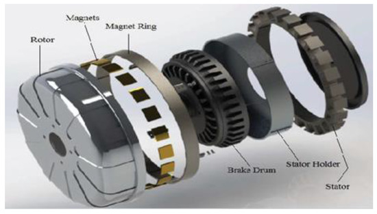
Figure 1.
Outer-rotor radial-type motor (hub motor) [7].
2. Materials and Methods
Hub Motor Design
In calculating the motor dimensions, the output power and nominal speed characteristics are decisive. The stator and rotor dimensions were calculated according to the boundary conditions in the design. In this study, to calculate the hub motor design parameters, the motor’s axial-length-to-pole-pitch (L/τ) ratio was taken as a reference. First, the motor output coefficient equation was used. The motor output power is given in Equation (1). is the motor output power (watt), E is the induced voltage (volt), and is the armature current (ampere).
In Equation (2), (Tesla) is the average air gap magnetic flux density, ac is the specific electrical loading (A/mm), is the stator outer diameter (mm), L is the motor axial length (mm), and n is the motor speed (rad/s).
In Equation (3), C0 is the motor output coefficient.
In Equation (5), τ is the pole pitch (mm) and is the circumferential distance corresponding to one pole, and P is the total number of poles.
The geometric parameters of the outer-rotor BLDC motor are shown in Figure 2.
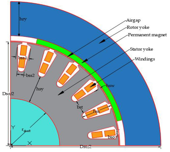
Figure 2.
Geometric parameters of the outer-rotor BLDC motor.
In Equation (6), δ is the air gap length (mm), is the magnet thickness (mm), and is the rotor yoke height (mm).
In Equation (7), is the tooth width (mm), is the air gap radius (mm), is the slot edge height (mm), is the stator slot number, and is the top slot width (mm).
In Equation (8), is the slot height (mm).
In Equation (9), is the stator yoke height (mm), and is the shaft radius (mm).
In Equation (10), is the flux density (Tesla) formed in the stator yoke.
The hub motor specifications, considering taken as the base, are given in Table 1.

Table 1.
Hub motor specifications (L/τ = 0.75).
The hub motor dimensions are given in Table 2.
Table 2.
Hub motor dimensions (L/τ = 0.75).
Since the saturation state of the ferromagnetic material used in the motor design is examined, the B-H curve for the M19_24G material is given in Figure 3. A linear increase extends up to approximately 1.6 Tesla, as seen in the M19_24G curve. After 1.6 Tesla, the curve begins to bend. It is observed that it passes into the saturation region, at a value of approximately 1.8 Tesla.
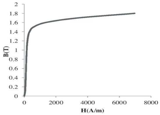
Figure 3.
M19_24G B-H curve [25].
There are four different slot types available for the user to examine in the Ansys software. Considering the maximum efficiency, the slot type shown in Figure 4a was selected for the motor. In this slot type, iron losses are due less to the slot edge height and geometric structure. A two-layer concentrated winding is preferred for the winding selection to achieve favorable operation parameters [6]. The two-layer winding connections are shown in Figure 4b.
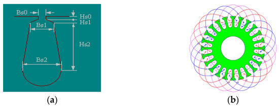
Figure 4.
(a) Slot type of hub BLDC motor, and (b) double-layer winding connection.
Figure 5 shows the B-H curve of the XG196/96 magnet. In the XG196/96 magnet, after being magnetized to the saturation point in a closed circuit when the magnetic field strength is zero, the flux density remaining in the magnet is 0.96 Tesla. After reaching saturation, the magnetic field strength that is required in order to bring the polarization back to zero is −690 kA/m [9].
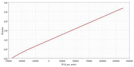
Figure 5.
XG196/96 B-H curve.
3. Results and Discussions
3.1. Hub Motor Analysis Results (L/τ = 0.75)
In this section, the rated torque, rated power, rated speed, and efficiency analysis were performed for the hub motor according to an axial-length-to-pole-pitch ratio of 0.75. The efficiency-speed characteristics and torque-speed characteristics of the hub motor were investigated. The obtained analysis results were compared for axial-length-to-pole-pitch ratios of 1, 1.5, 2, and 3, respectively. The hub motor simulation results are given in Table 3.
Table 3.
Hub motor simulation results (L/τ = 0.75).
According to the Ansys/RMxprt simulation results, the efficiency-speed and the torque-speed curves obtained for the rated speed and rated torque are shown in Figure 6a,b, respectively.
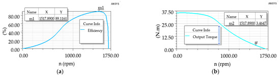
Figure 6.
(a) Efficiency vs. speed curve, and (b) torque vs. speed curve.
The hub motor flux distribution is shown in Figure 7.
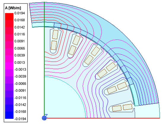
Figure 7.
Hub motor flux distribution.
3.2. Examination of Motor’s Axial-Length-to-Pole-Pitch Ratio (L/τ)
In this section, the effect of the change in the motor L/τ was examined for the motor parameters. The Dsi/Dso was taken as a constant (0.45). Initially, when this ratio was 1, the Dso was 90, and the L was 71 mm. The Dro, δ, air gap average flux density, ac, hm, number of poles, number of stator slots, number of conductors per slot, and conductor diameter were kept constant. The Dsi and magnet width (mm) were updated at each step according to the L/τ. The magnet width was also changed from 58 mm to 33.43 mm. Thus, the pole arc/pole pitch ratio was fixed at each step. In the second step, when the motor L/τ was 1.5, the Dso was 80 mm, and the L was 93 mm. Similarly, when the L/τ was 2, the Dso was 72 mm, and the L was 113 mm. Finally, when the L/τ was 3, the Dso was 63 mm, and the L was 147 mm. According to the simulation results obtained, the efficiency vs. speed curve is given in Figure 8a. The specific electric loading-ac vs. the airgap flux density curve is given in Figure 8b.
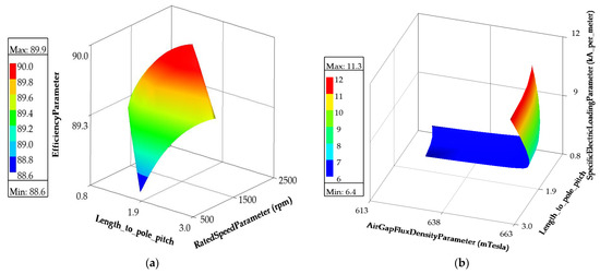
Figure 8.
(a) Efficiency vs. speed vs. length-to-pole-pitch-ratio curve, and (b) specific electric loading(ac) vs. airgap flux density vs. length-to-pole-pitch-ratio curve: L/τ = 0.75, L/τ = 1, L/τ = 1.5, L/τ = 2, L/τ = 3.
It was determined that the changes in the efficiency level were very small when the motor axi-al length increased. It was also observed that the speed change decreased from 1500 rpm to 1080 rpm.
In Figure 9, the effect of the ratio of the motor on some parameters is shown and represented by the rated speed vs. length to pole pitch, the total net weight vs. length to pole pitch, and the armature phase resistance vs. length to pole pitch a, b and c curves, respectively. The motor axial length value range is 65–150 mm, and the stator outer diameter value range is 63–110 mm. The number of magnet poles is fixed (p = 4). The parametric analysis was performed according to these value ranges. As the L/τ increased, the armature phase resistance increased, because when the axial length of the motor increased, the conductor length also increased. The total net weight increased from 6 to 16 kg due to the increase in axial length. The rated torque was also around 3 Nm at the beginning but exceeded 4 Nm in the final state. A very significant decrease in the rated speed was observed. The reference rate was observed dropping from 1500 to 1000 rpm.
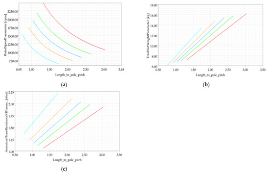
Figure 9.
Effect of L/τ.
In Figure 10a, the average flux density in the rotor yoke is 1.65 Tesla. The average flux density of the stator yoke is 1.30 Tesla. The stator tooth flux density is 1.40 Tesla, and the air gap flux density is 0.61 Tesla. In cases b–e, the stator yoke flux density, air gap flux density, and stator tooth flux density are approximate values. The rotor yoke flux density is 0.34 Tesla in the last case. Considering the magnetic circuit of the motor, the flux formed in the magnet passes through the stator and rotor yokes and completes its circuit. As the rotor yoke height increases, the length of the flux path increases. In this case, a lower flux density occurs because the flux path in the rotor is long.
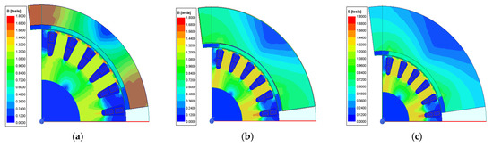
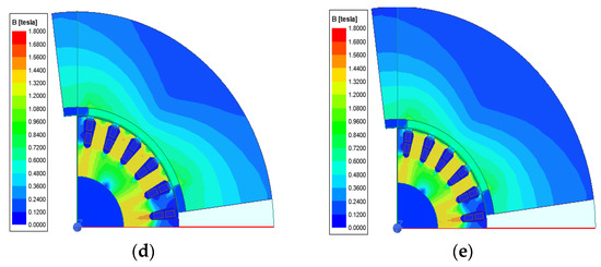
Figure 10.
Flux density: (B) (a) L/τ = 0.75, (b) L/τ = 1, (c) L/τ = 1.50, (d) L/τ = 2, (e) L/τ = 3.
Torque ripple in electrical machines is caused by factors including cogging torque, mechanical motion, air gap harmonics, and magnetomotor force [26,27]. The torque ripple is defined as the percentage of the difference between the maximum torque Tmax and the minimum torque Tmin compared to the average torque Tavg.
In Figure 11a, a torque ripple of 1 Nm occurs every 2 ms. The maximum torque is ob-served at 5.9 Nm. The torque ripple is at 137.37%. In Figure 11b, a torque ripple of 1 Nm occurs every 1.50 ms. The maximum torque is observed at 3.47 Nm. The torque ripple is at 152.47%. In Figure 11c, a torque ripple of 1.30 Nm occurs every 1.50 ms. The maximum torque is observed at 4.43 Nm. The torque ripple is at 166.63%. In Figure 11d, a torque ripple of 1.40 Nm occurs every 1.90 ms. The maximum torque is observed at 4.69 Nm. The torque ripple is at 161.71%. In Figure 11e, a torque ripple of 1.30 Nm occurs every 2 ms. The maximum torque is observed at 5.08 Nm. The torque ripple is at 150.49%.
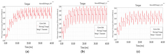
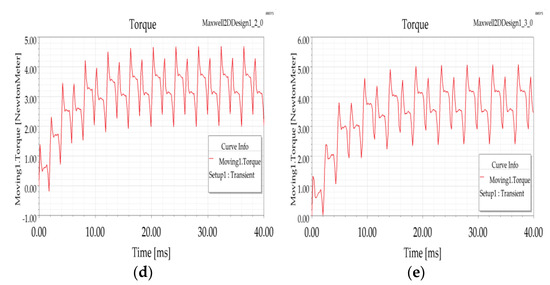
Figure 11.
Moving torque: (a) L/τ = 0.75, (b) L/τ = 1, (c) L/τ = 1.50, (d) L/τ = 2, (e) L/τ = 3.
High cogging torque causes the motor to vibrate, which is undesirable. Cogging torque is calculated by Equation (12). Reducing also reduces the cogging torque. Cogging torque curves obtained according to L/τ ratio are shown in Figure 12.
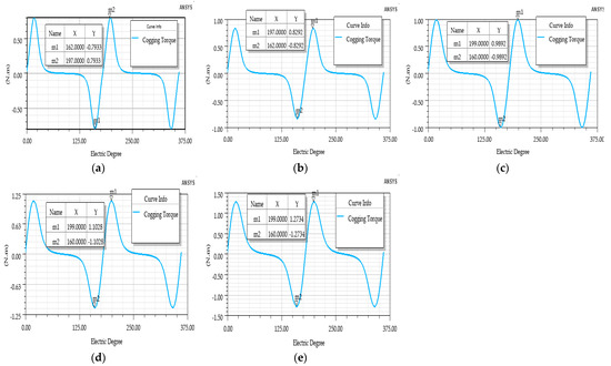
Figure 12.
Cogging torque: (a) L/τ = 0.75, (b) L/τ = 1, (c) L/τ = 1.50, (d) L/τ = 2, (e) L/τ = 3.
In Figure 12a, the cogging torque is 0.7933 Nm. In Figure 12b, the cogging torque is 0.8292 Nm. In Figure 12c, the cogging torque is 0.9892 Nm. In Figure 12d, the cogging torque is 11028 Nm. In Figure 12e, the cogging torque is 1.2734 Nm.
Table 4 shows the comparison of the hub motor results.
Table 4.
Comparison of hub motor results.
In Table 4, it is observed that the L/τ ratio changes with the motor parameters, such as the torque, the torque/weight ratio, motor volume, torque/volume, efficiency, and cogging torque. While the torque/weight is the highest and the volume is the smallest at 0.75, the torque is the highest at 3 and the efficiency is the highest at 1.50.
3.3. Optimization of Stator Outer Diameter and Axial Length by Genetic Algorithm
The genetic algorithm process basically consists of five stages. In the first step, the population of the problem is created. Then the fitness value of each individual is calculated. The selection is made using methods that include the roulette wheel and the tournament method. After the selection, the crossover operator is applied. In the last step, the individuals are obtained by applying the mutation operator from the new population. The genetic algorithm continues until it finds the criterion for the best solution to the problem [28,29].
The stator outer diameter and axial length were optimized by the genetic algorithm process according to the flowchart shown in Figure 13. The genetic algorithm process was carried out with the help of the optimization tool in Ansys Electronics Desktop software. The lower and upper limit values for the stator outer diameter and axial length were determined. While determining these limit values, the initial physical dimensions of the motor were taken as the reference. In the genetic algorithm optimization tool, the population size was chosen to be 50, the selection method was chosen to be the roulette wheel, two-point crossover, and the mutation probability was chosen to be 0.05. The stator outer diameter and axial length values that provided the maximum efficiency were obtained.
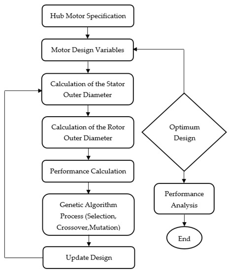
Figure 13.
Flow chart for genetic algorithm process.
The lower limit value of the stator outer diameter was chosen to be 100 mm, and the upper limit value was chosen to be 120 mm. The lower limit value of the motor axial length was chosen to be 55 mm, and the upper limit value was chosen to be 75 mm. The hub motor design variables are shown in Table 5.
Table 5.
Hub motor design variables.
At the end of the genetic algorithm process (see Figure 14), the highest efficiency (89.43%) was obtained in the 156th iteration. The stator outer diameter and the axial length that were formed at this efficiency point were 100.82 mm and 73.20 mm, respectively.
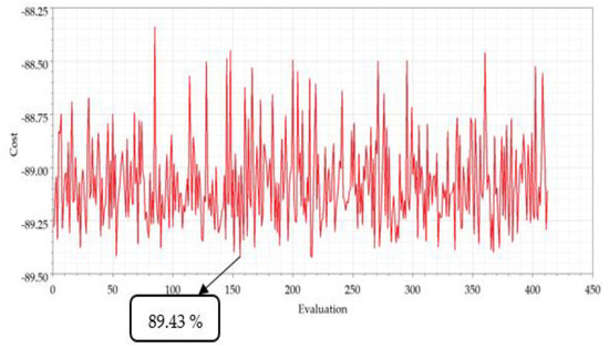
Figure 14.
Genetic algorithm process efficiency graph.
A 2D analysis was performed according to the RMxprt result obtained by the genetic algorithm. In Figure 15a, the stator teeth flux density is 1.5 Tesla, the stator yoke flux density is 1.4 Tesla, the rotor yoke flux density is 1.2 Tesla, and the air gap flux density is 0.65 Tesla. The flux density values are all within the limits. In Figure 15b, it was observed that the flux distribution was uniform.
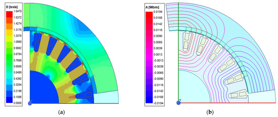
Figure 15.
(a) Genetic algorithm magnetic flux density; (b) genetic algorithm flux distribution.
At the end of the genetic algorithm process, the torque was 3.79 Nm, the torque/weight was 0.54 Nm/kg, the volume was 1126 cm3, the torque/volume was 0.00336 Nm/cm3, the efficiency was 89.43%, and the cogging torque was 0.93 Nm. Additionally, the optimal L/τ ratio was 1.84.
4. Conclusions
In this study, the motor L/τ ratio was investigated for the hub BLDC motor. The relationship between the motor axial length and diameter is very important for motor sizing. The weight and volume of the motor affect the efficiency, as they affect the material loss. Therefore, the most appropriate value for its axial length and diameter should be calculated. The hub motor’s performance analysis in terms of L/τ was an original work. The motor dimensions were determined by considering the motor sizing boundary conditions. According to these conditions, the ratio of L/τ was increased. As this ratio increased, the axial length increased. The rotor inner diameter, stator outer diameter, and stator inner diameter decreased. Iron losses decreased due to the smaller stator volume. The stator outer diameter and axial length of the hub motor were selected as variables in the genetic algorithm process. Then, the optimal axial-length-to-pole-pitch ratio was found. The consequences are listed below.
- The increase in phase resistance caused copper loss. There was a decrease in the efficiency performance (0.57%) when comparing the first case to the last case.
- The highest torque, volume, and cogging torque values were obtained at a ratio of 3.
- When the motor ratio was at 0.75, the lowest volume, torque, and cogging torque values were observed. In addition, the highest efficiency, torque/volume, and torque/weight values were obtained.
- It was observed that the torque, motor volume, cogging torque, specific electrical loading, and phase resistance increased as the ratio increased. The torque/weight, torque/volume, rated speed, and flux density in the rotor yoke decreased.
- When the first ratio and the last ratio were compared, the efficiency change increased by 0.35%, the torque change decreased by 28.65%, and the volume change increased by 55%.
- The efficiency value obtained by the genetic algorithm was 0.357% higher than the initial (L/τ = 0.75) efficiency value. The weight was 16.66% higher, the volume was 11.19% larger, and the torque was 8.70% higher.
This study was conducted in order to guide motor designers and researchers in the initial design of outer-rotor electric motors that are to be especially used in light electric vehicles.
Author Contributions
Conceptualization, O.T. and N.F.O.S.; methodology, N.F.O.S.; software, O.T.; validation, O.T. and N.F.O.S.; formal analysis, N.F.O.S. and O.T; investigation, O.T. and N.F.O.S.; resources, O.T. and N.F.O.S.; data curation, O.T.; writing—original draft preparation, O.T. and N.F.O.S.; writing—review and editing, N.F.O.S.; visualization, O.T.; supervision, N.F.O.S.; project administration, N.F.O.S.; funding acquisition, O.T. and N.F.O.S. All authors have read and agreed to the published version of the manuscript.
Funding
This research received no external funding.
Institutional Review Board Statement
Not applicable.
Informed Consent Statement
Not applicable.
Data Availability Statement
All research data used to assist in the findings of this work are included within the manuscript.
Conflicts of Interest
The authors declare no conflict of interest.
References
- Hao, H.; Shen, J.; Yuan, C.; Qu, Q. Influences of machine structure on high speed PM BLDC motor. In Proceedings of the 17th International Conference on Electrical Machines and Systems (ICEMS), Pune, India, 17 October 2014; pp. 3309–3312. [Google Scholar]
- Li, H.; Li, W.; Ren, H. Fault-Tolerant Inverter for High-Speed Low-Inductance BLDC Drives in Aerospace Applications. IEEE Trans. Power Electron. 2016, 32, 2452–2463. [Google Scholar] [CrossRef]
- Karnavas, Y.L.; Chasiotis, I.D.; Gkiokas, A.D. An Investigation Study Considering the Effect of Magnet Type, Slot Type and Pole-Arc to Pole-Pitch Ratio Variation on PM Brushless DC Motor Design. In Proceedings of the 2018 5th International Conference on Mathematics and Computers in Sciences and Industry (MCSI), Corfu, Greece, 25–27 August 2018; pp. 7–13. [Google Scholar] [CrossRef]
- Hwang, K.-Y.; Lin, H.; Rhyu, S.-H.; Kwon, B.-I. A Study on the Novel Coefficient Modeling for a Skewed Permanent Magnet and Overhang Structure for Optimal Design of Brushless DC Motor. IEEE Trans. Magn. 2011, 48, 1918–1923. [Google Scholar] [CrossRef]
- Wang, D.; Wang, X.; Kim, M.-K.; Jung, S.-Y. Integrated Optimization of Two Design Techniques for Cogging Torque Reduction Combined With Analytical Method by a Simple Gradient Descent Method. IEEE Trans. Magn. 2012, 48, 2265–2276. [Google Scholar] [CrossRef]
- Tosun, O.; Serteller, N.F.O. Analysis of Brushless Direct Current Motor Stator Slot Geometry and Winding Type with FEM. In Proceedings of the 3rd International Symposium on Multidisciplinary Studies and Innovative Technologies (ISMSIT), Ankara, Turkey, 20–22 October 2019; pp. 105–111. [Google Scholar]
- Uygun, D.; Selim, S. Design and dynamic study of a 6 kW external rotor permanent magnet Brushless DC motor for electric drivetrains. In Proceedings of the 2015 IEEE 5th International Conference on Power Engineering, Energy and Electrical Drives (POWERENG), Riga, Latvia, 20–22 October 2015; pp. 87–92. [Google Scholar]
- Chasiotis, I.D.; Karnavas, Y.L. A computer aided educational tool for design, modeling, and performance analysis of Brushless DC motor in post graduate degree courses. Comput. Appl. Eng. Educ. 2018, 26, 749–767. [Google Scholar] [CrossRef]
- Zhilichev, Y. Analysis of Permanent Magnet Demagnetization Accounting for Minor B–HB–H Curves. IEEE Trans. Magn. 2008, 44, 4285–4288. [Google Scholar] [CrossRef]
- Bernard, N.; Martin, F.; Zaïm, M.E.-H. Design Methodology of a Permanent Magnet Synchronous Machine for a Screwdriver Application. IEEE Trans. Energy Convers. 2012, 27, 624–633. [Google Scholar] [CrossRef]
- Uzhegov, N.; Kurvinen, E.; Nerg, J.; Pyrhonen, J.; Sopanen, J.T.; Shirinskii, S. Multidisciplinary Design Process of a 6-Slot 2-Pole High-Speed Permanent-Magnet Synchronous Machine. IEEE Trans. Ind. Electron. 2015, 63, 784–795. [Google Scholar] [CrossRef]
- Ismagilov, F.R.; Uzhegov, N.; Vavilov, V.E.; Bekuzin, V.I.; Ayguzina, V.V. Multidisciplinary Design of Ultra-High-Speed Electrical Machines. IEEE Trans. Energy Convers. 2018, 33, 1203–1212. [Google Scholar] [CrossRef]
- Messine, F. Deterministic global optimization using interval constraint propagation techniques. RAIRO-Oper. Res. 2004, 38, 277–293. [Google Scholar] [CrossRef][Green Version]
- Ki-Chan, K.; Ju, L.; Hee, J.K.; Dae, H.K. Multiobjective Optimal Design for Interior Permanent Magnet Synchronous Motor. IEEE Trans. Magn. 2009, 45, 1780–1783. [Google Scholar] [CrossRef]
- Stipetic, S.; Miebach, W.; Zarko, D. Optimization in design of electric machines: Methodology and workflow. In Proceedings of the 2015 Intl Aegean Conference on Electrical Machines & Power Electronics (ACEMP), 2015 Intl Conference on Optimization of Electrical & Electronic Equipment (OPTIM) & 2015 Intl Symposium on Advanced Electromechanical Motion Systems (ELECTROMOTION), Side, Turkey, 2–4 September 2015; pp. 441–448. [Google Scholar] [CrossRef]
- Ismagilov, F.R.; Vavilov, V.Y.; Ayguzina, V.V.; L’vov, N.Y.; L’vovskiy, T.A. Optimal design of electric machines by using genetic algorithms: Mathematical apparatus to determine machine parameters. In Proceedings of the 2019 International Conference on Electrotechnical Complexes and Systems (ICOECS), Ufa, Russia, 21 October 2019; pp. 1–5. [Google Scholar] [CrossRef]
- Bramerdorfer, G. Multiobjective electric machine optimization for highest reliability demands. CES Trans. Electr. Mach. Syst. 2020, 4, 71–78. [Google Scholar] [CrossRef]
- Finken, T.; Felden, M.; Hameyer, K. Comparison and design of different electrical machine types regarding their applicability in hybrid electrical vehicles. In Proceedings of the 2008 18th International Conference on Electrical Machines, Vilamoura, Portugal, 6–9 September 2008; pp. 1–5. [Google Scholar]
- Liu, X.; Slemon, G. AN improved method of optimization for electrical machines. IEEE Trans. Energy Convers. 1991, 6, 492–496. [Google Scholar] [CrossRef]
- Lukaniszyn, M.; Jagiela, M.; Wrobel, R. Optimization of Permanent Magnet Shape for Minimum Cogging Torque Using a Genetic Algorithm. IEEE Trans. Magn. 2004, 40, 1228–1231. [Google Scholar] [CrossRef]
- Le Besnerais, J.; Lanfranchi, V.; Hecquet, M.; Brochet, P. Multiobjective Optimization of Induction Machines Including Mixed Variables and Noise Minimization. IEEE Trans. Magn. 2008, 44, 1102–1105. [Google Scholar] [CrossRef]
- Pellegrino, G.; Cupertino, F. FEA-based Multi-Objective Optimization of IPM Motor Design Including Rotor Losses. In Proceedings of the IEEE Energy Conversion Congress and Exposition (ECCE), Atlanta, GA, USA, 12–16 September 2010; pp. 3659–3666. [Google Scholar]
- Bianchi, N.; Durello, D.; Fornasiero, E. Multi-Objective Optimization of a PM Assisted Synchronous Reluctance Machine, Including Torque and Sensorless Detection Capability. In Proceedings of the 6th IET International Conference on Power Electronics, Machines and Drives (PEMD 2012), Bristol, UK, 27–29 March 2012; pp. 1–6. [Google Scholar]
- Lee, C.-S.; Kim, H.-J. Harmonic Order Analysis of Cogging Torque for Interior Permanent Magnet Synchronous Motor Considering Manufacturing Disturbances. Energies 2022, 15, 2428. [Google Scholar] [CrossRef]
- Minaz, M.R.; Çelebi, M. Design and analysis of a new axial flux coreless PMSG with three rotors and double stators. Results Phys. 2017, 7, 183–188. [Google Scholar] [CrossRef]
- Havel, A.; Sobek, M.; Stepanec, L.; Strossa, J. Optimization of Permanent Magnet Parameters in Axial Flux Rotary Converter for HEV Drive. Energies 2022, 15, 724. [Google Scholar] [CrossRef]
- Bozkurt, A.; Baba, A.F.; Oner, Y. Design of Outer-Rotor Permanent-Magnet-Assisted Synchronous Reluctance Motor for Electric Vehicles. Energies 2021, 14, 3739. [Google Scholar] [CrossRef]
- Prasetio, K.D.; Yuniarto, M.N. Design and Performance Test of Axial Halbach Brushless DC Motor with Power Density 1.5 Kw/Kg. J. Tek. ITS 2017, 5, 2. [Google Scholar] [CrossRef]
- Çunkaş, M.; Akkaya, R. Design optimization of induction motor by genetic algorithm and comparison with existing motor. Math. Comput. Appl. 2006, 11, 193–203. [Google Scholar] [CrossRef]


Publisher’s Note: MDPI stays neutral with regard to jurisdictional claims in published maps and institutional affiliations. |
© 2022 by the authors. Licensee MDPI, Basel, Switzerland. This article is an open access article distributed under the terms and conditions of the Creative Commons Attribution (CC BY) license (https://creativecommons.org/licenses/by/4.0/).