Abstract
The deflection of the endplate under the clamping force has a vital effect on fuel cell performance. An optimal cross-sectional shape with a high moment of inertia of the endplate is significant to maximize the bending stiffness of the fuel cell stack. Five cross-sectional shapes (rectangular, round, parabolic, rectangular + round, and rectangular + parabolic) of the typical endplates are proposed. An analytical study on the moments of inertia of the endplates is introduced and analyzed. The maximum moments of inertia of the cross-sections are obtained and displayed in a matrix in thickness and length. The statistical results show that the “rectangular + parabolic” cross-section has the advantage of wide dimensional size while maintaining a high moment of inertia. Finally, the analytical studies are validated by a finite element method (FEM) and the corresponding trends are highly agreed upon. The maximum moment of inertia of the parabolic endplate is 85.71% higher than the rectangular endplate with a thickness of 80 mm, and the corresponding contact pressure variance is 6.15% less than the rectangular endplate. The presented analytical study is significant and effective to optimize the cross-sectional shape of the endplate and provide an endplate design direction for a large fuel cell stack.
1. Introduction
As environmental problems become more prominent, more and more attention is turning toward clean energy worldwide. The proton exchange membrane fuel cell (PEMFC) can directly convert chemical energy into electrical energy with high efficiency. Hydrogen is a raw material whose production is only water, which makes PEMFC a promising energy source [1,2,3].
PEMFC surpasses the efficiency limitation brought by the Carnot cycle with a high efficiency, which greatly reduces the waste of energy [4]. Meanwhile, PEMFC does not need a mechanical transmission mechanism, the structure is compact without working noise, and its life and reliability levels are high [5]. In addition, PEMFC also has the advantages of low operating temperature, and good cold start performance, which grant it potential in many fields, such as power stations, vehicles, and aviation [6]. The application of PEMFC is beneficial to sustainable development.
During the fuel cell stack assembly, there is inevitably a deflection of the endplates. The deflection will cause uneven contact pressure distribution on the membrane electrodes assembly (MEA), and lead to differences in the fuel cell electro-chemical reactions [7,8,9].
Improper contact pressure will affect the transfer of electrons [10,11] and the fuel supply [12,13]. Low contact pressure causes a small contact area and a large interfacial contact resistance, which brings ohmic voltage loss [14,15], a large contact pressure causes excessive gas diffusion layer (GDL) deformation, decreases its porosity and permeability, and leads to concentration voltage loss [16]. The uniform contact pressure distribution is of great significance to the high performance of a fuel cell stack.
Increasing the thickness of the endplates is an effective way to reduce the deflection of the endplates and improve the uniformity of contact pressure [17], but it will also increase the total mass and reduce the volume power density, which is important in the evaluation of the fuel cell stack. Therefore, it is necessary to properly design the fuel cell endplates before the assembly of the fuel cell stack.
Asghari et al. [18] designed and machined an endplate for a 5 kW fuel cell stack, and aluminum alloy was selected as the endplate material. The endplate thickness was optimized based on the evaluation of the tested deflection. The strain of the endplate with low mass is the optimization objective. The experiment did not consider the effect of the local dimensions of the endplate on the uniformity of the integrated force distribution inside the stack.
Lin et al. [19] proposed a multi-objective endplate optimization method to reduce the endplate mass and improve the uniformity of the contact pressure distribution in the steel strip-strapped fuel cell stack. The two-dimensional optimization of the endplate cross-section was divided into two steps: Shape optimization and topology optimization. Based on the two-dimensional optimization, the three-dimensional model of the endplate was optimized by the parametric modeling method. Lin et al. [20] used a multi-objective topology optimization method based on the finite element method to obtain the maximum stiffness of the endplate and ensure the integrated force is uniformly distributed inside the stack, while the material distribution under the maximum stiffness of the end plate was employed to make the pressure distribution inside the stack more uniform. The internal structure of the stack model established in this paper is replaced by rectangular plates, ignoring the influence of the bipolar plate ridge and flow channel, so the model has a large deviation.
Carral et al. [21] used experiments to study the deformation of the endplate under the action of the clamping force. A strain gauge was utilized to measure the strain of different parts of the endplate. The formula was deduced to fit the date. The experimental value and the theoretical value have a good consistency. Zhang et al. [22] designed a downwardly inclined endplate and optimized the structural size. After the optimization, the uniformity of contact pressure distribution was improved. Liu et al. [23] proposed a new pneumatic clamping device for the endplates where uniform pressure was applied on the endplate by nitrogen gas. Compared with the traditional clamping method, the new device can effectively improve the uniformity of stress distribution. Tests showed that the new device can effectively reduce the internal ohmic impedance by 18%. Alizadeh et al. [24] also proposed a similar device to obtain a more uniform pressure distribution. Qiu et al. [25] established an intelligent method to optimize the uniformity of pressure distribution inside the fuel cell stack. It can greatly simplify the limits of simulation and provide a novel idea. However, the trained model had certain shortcomings with not many data. It can only be used for a specific fuel cell stack. Chang [26] proposed a bendable fuel cell, where the degree of bending is controlled by the endplates. The test results show that the ohmic impedance and Faraday impedance of the fuel cell after bending are significantly reduced, which also brings about a significant improvement in performance.
Wei [27] studied the compression effect on GDL through FEM. A simulated annealing algorithm was used then to optimize the endplate shape and topology. Zhang et al. [28] used the FEM to obtain three topology structures of lightweight endplates. A comparison was made between those endplates before and after optimization. The results showed that the optimized endplates can reduce the mass of the endplates and improve the uniformity of the contact pressure. Jiang [29] established a multi-objective fuel cell endplate topology optimization model based on topology optimization theory and finite element method considering several design indexes. The finite element analysis was performed on several groups of endplates with the same cross-sectional area and different cross-sectional forms to determine the optimal cross-sectional shape by the root mean square of the displacement of the contact surface between the endplate and the bipolar plate.
Usually, the maximum cross-sectional stiffness endplate should be selected by taking the strain energy at the contact surface of the endplate and the stack internal component as the minimum target, the root mean square of displacement as the minimum target, and the weighted value of both as the minimum target for the basic shape selection of the end plate, respectively. However, no corresponding relationship is built between the shape of the maximum cross-sectional stiffness and the endplate of different sizes. At the same time, the FEM needs a great deal of calculation time and resources, adding to the convergence difficulty, which will need enormous calculation resources.
To simplify the analysis process and obtain a reliable result, a theoretical method is needed to replace the FEM and experiment method. In this study, a theoretical calculation method is proposed to analyze different endplate cross-sectional shapes for optimization. The inertia moments of endplates with different cross-sectional shapes in the same area will be presented to evaluate the optimal endplate shapes of different sizes. The result is then validated by the FEM models. Through the theoretical method, the analysis process is simple and could save a great deal of time and resources.
2. Moment of Inertia Analysis of Different Cross-Sectional Endplates
In the case of the same cross-sectional area, under the clamping force of the fuel cell stack, the deflections of different cross-sectional shapes of the endplate are different. The cross-sectional stiffness and endplate deflection are inverse relations. The cross-sectional bending stiffness is shown as follows [30]:
where K is the cross-sectional bending stiffness, E is the material modulus of elasticity, I is the cross-sectional moment of inertia, M is the bending moment per unit cross-section, and is the cross-sectional curvature. It can be found that the cross-sectional moment of inertia can represent the bending stiffness to evaluate the endplate deflection.
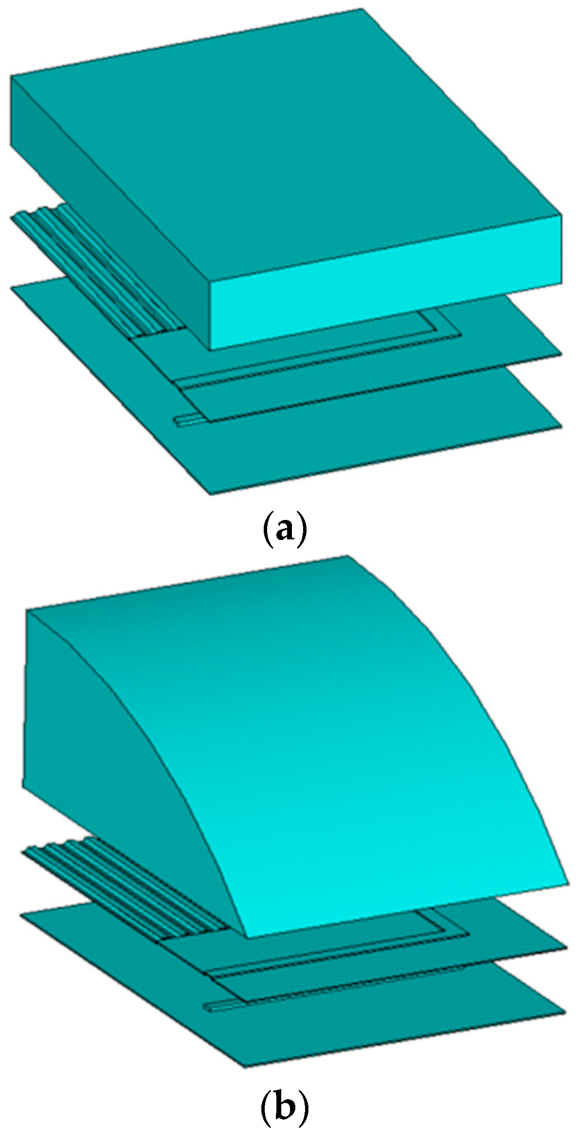
For the cross-section shape design of the fuel cell endplate, five typical cross-sectional shapes (rectangular, round + parabolic) and two combination shapes (rectangular + round and rectangular + parabolic) are proposed as shown in Figure 1. The center of coordinates in each endplate is the centroid of each shape. The moments of inertia are calculated to compare them with the same cross-sectional area based on the rectangular shape.

Figure 1.
Diagram of the endplates with different cross-sections: (a) Rectangular; (b) round; (c) parabolic; (d) rectangular + round; (e) rectangular + parabolic.
The length of the rectangular endplate is equal to the bipolar plate length which is constant in this study for comparison. So, the unique parameter that determines the area is the height of the endplate (i.e., the thickness of the endplates), which can be called the “characteristic parameter” of the different cross-sectional endplates. The characteristic parameter of the round cross-section is the radius . The characteristic parameter of the parabolic cross-section is the parabolic quadratic term coefficient . The characteristic parameter of the rectangular + round cross-section is the rectangular occupation factor () and the round radius . The characteristic parameter of the rectangular + parabolic cross-section is the rectangular occupation factor () and the parabolic quadratic term coefficient
According to Figure 1, the unique characteristic parameters of each cross-sectional shape can be determined. The area of each shape can be adjusted to be equal to the rectangle by the characteristic parameters. The thickness of the rectangular endplate is the “Equivalent thickness” of the rectangular endplate for all five endplates with the same cross-sectional area. The next step is to find the maximum moment of inertia.
- (1)
- Rectangular cross-section
The moment of inertia for the rectangular cross-section to its centroid is:
where is the length of the rectangle and is the height of the rectangle.
- (2)
- Round cross-section
The center angle of the round endplate is less than or equal to 180°, so the moment of inertia of the round cross-section to its centroid can be expressed as:
The center angle is:
The cross-sectional area of the endplate is:
The moment of inertia of the round endplate to the round center is:
The distance between the round center and the round centroid is:
The moment of inertia of the round endplate to the round centroid is:
- (3)
- Parabolic cross-section
Since the bottom length of the parabolic endplate is at as presented, the parabolic quadratic term parameter and the parabolic zero term parameter have the relationship as shown:
The area of the parabola is:
The moment of inertia of the parabolic endplate to the bottom edge is:
The distance between the bottom edge and the parabola centroid is:
The moment of inertia of the parabolic endplate to the parabola centroid is:
- (4)
- Rectangular + round cross-section
The center angle of the round part is:
The area of the round part is:
The area of the rectangular part is:
where is the height of the rectangular part.
The total cross-sectional area of the endplate is:
The moment of inertia of the rectangular part to the rectangle centroid is:
The moment of inertia of the round part to the round centroid is:
where is the moment of inertia of the round part to the round centroid, is the moment of inertia of the round part to the round center, and is the distance between the round center and the round centroid.
The distance between the endplate centroid to the bottom edge is:
where the is the distance between the endplate centroid to the bottom edge, is the distance between the round part centroid to the bottom edge, is the distance between the rectangular part centroid to the bottom edge, and is the distance between the round part round center to the round part centroid.
The distance between the rectangular part centroid to the endplate centroid is:
The distance between the round part centroid to the endplate centroid is:
The moment of inertia of the endplate to the endplate centroid is:
- (5)
- Rectangular + parabolic cross-section
Since the bottom length of the parabolic end plate is , the parabolic quadratic term parameter and the parabolic zero term parameter have the relationship as shown:
The area of the parabolic part is:
The area of the rectangular part is:
where is the height of the rectangular part.
The cross-sectional area of the endplate is:
The moment of inertia of the parabolic part to the parabola centroid is:
where is the moment of inertia of the parabolic part to the bottom edge of the parabolic part, and is the distance between the parabola centroid to the bottom edge of the parabolic part.
The moment of inertia of the rectangular part to the rectangle centroid is:
The distance between the endplate centroid to the endplate’s bottom edge is:
where is the distance between the endplate centroid to the endplate’s bottom edge, is the distance between the parabola centroid to the endplate’s bottom edge, and is the distance between the rectangle centroid to the endplate’s bottom edge.
The distance between the rectangle centroid to the endplate centroid is:
The distance between the parabola centroid to the endplate centroid is:
The moment of inertia of the endplate to the endplate centroid is:
The moment of inertia obviously depends on the size of the endplate. With different thicknesses and widths, the optimal cross-sectional shape is also different. It is necessary to take the size into consideration when the endplate has the maximum moment of inertia with different cross-sectional shapes.
Figure 2 shows the cross-sectional shape with the maximum moment of inertia with different sizes. The horizontal coordinate is the cross-sectional width, which corresponds with the bipolar plate size. The vertical coordinate is the equivalent thickness of the cross-section shape.
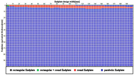
Figure 2.
The maximum moment of inertia with five different cross-section sizes.
It can be found that the parabola endplate has the maximum moment of inertia in different sizes (thickness and length), i.e., the parabola cross-section, which has a high proportion of the moment of inertia, is effective in the wide range design of the endplate. However, the endplate with a parabolic cross-section is difficult to manufacture. On the other hand, as the equivalent thickness of the endplate increases, the parabolic cross-section will approach a similar triangular shape and forms a sharp peak, which will result in concentration stress during the fuel cell stack assembly. Therefore, the parabolic endplate is better to be evicted for these reasons.
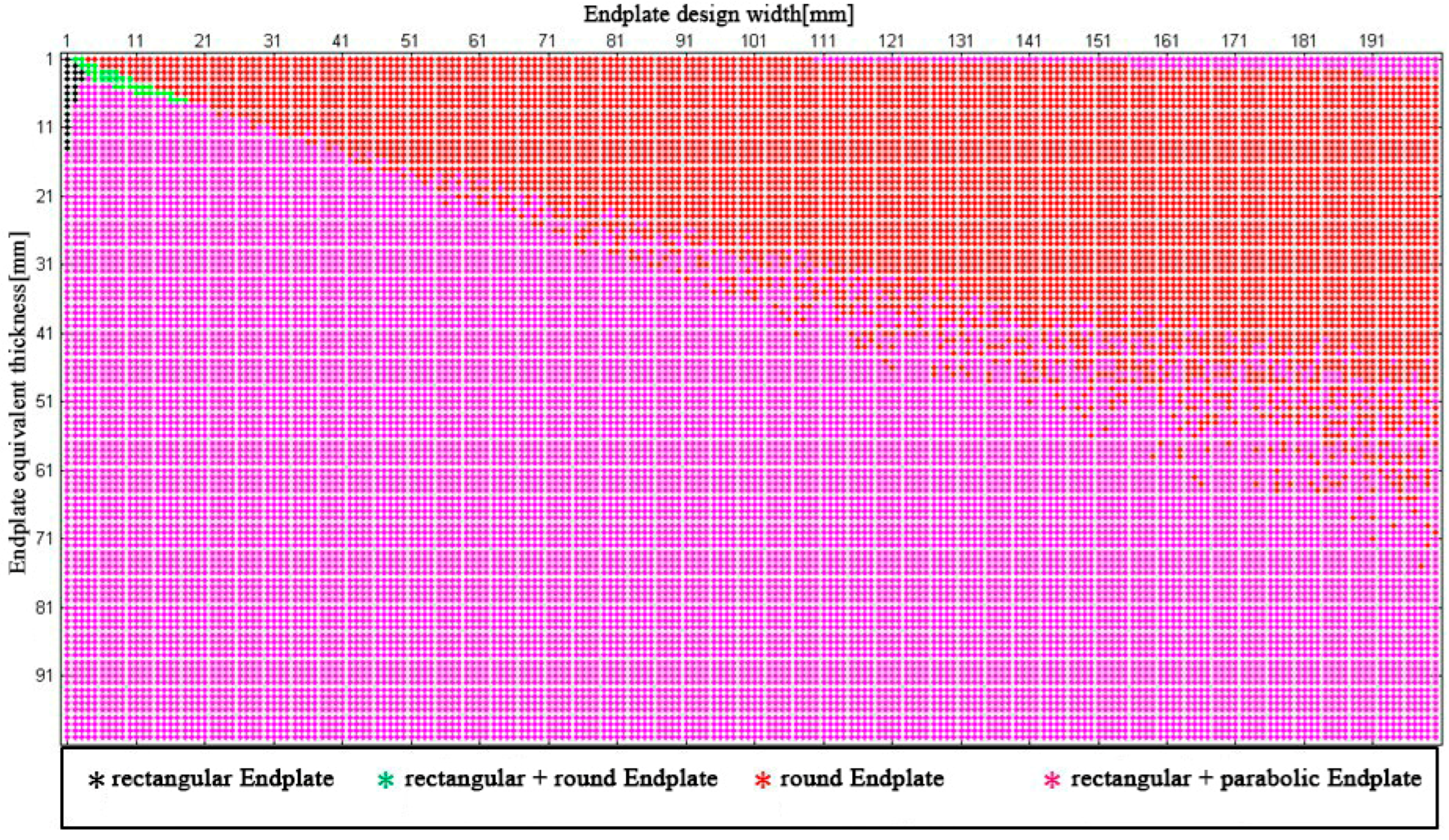
Figure 3 shows that the “rectangular + parabolic” endplate with the maximum moment of inertia has a large, occupied proportion in the wide dimensional size of the endplate, and then the round endplate. The rectangular endplate and the “rectangular + round” endplate only have a small specific region. Therefore, the “rectangular + parabolic “cross-section is suitable for a large length and width endplate design while maintaining a high moment of inertia.
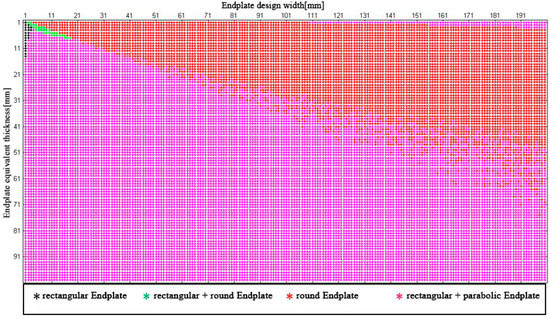
Figure 3.
Maximum moment of inertia with different sizes (thickness and width) of four different endplate cross-sectional shapes.
In these different cross-sectional shapes, the rectangular proportion factor of the “rectangular + parabolic” cross-section shape is set at 0.5, i.e., half rectangle and half parabolic. However, factor may also have an important effect on the maximum moment of inertia distribution.
Figure 4 shows the maximum moment of inertia matrix in the thickness and the length size when the factor varies between 0.1 and 0.9. It can be found that as the proportion of the rectangle in the “rectangular + parabolic” cross-section increases, the occupied region of the round endplate increases, but it is not obvious. The “rectangular + parabolic” cross-section still has the advantage in the endplate design with large thickness.
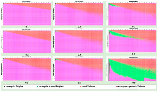
Figure 4.
Maximum moment of inertia occupation proportion under different sizes with different values of endplate cross-sectional shape.
On the other hand, at the value of 0.9, the “rectangular + round” endplate almost substitutes the “rectangular + parabolic” cross-section. For the endplate with a small thickness and large length, the round endplate is suitable; for endplates with a certain large thickness and length, the “rectangular + round” has an obvious advantage.
At present, the fuel cell stacks have a large active electro-chemical reaction area and endplates with small thickness; for the increasing requirements of high working current and high volumic power density, the round endplates are suitable for certain power of the fuel cell stack, e.g., 100 kW. However, if the fuel cell stack power is over 100 kW, the clamping force is relatively high. In order to avoid the leakage of the high-pressure fuel and air, the endplate has a large thickness, and then the “rectangular + round” endplate is preferred in the pre-design.
3. Validation with Finite Element Method (FEM)
The optimal cross-sectional shape of the endplate could be selected according to the presented matrix including the maximum moment of inertia distribution, then a finite element model will be developed to validate the moment of inertia of different cross-sectional shapes, and the corresponding contact pressure variance will also be analyzed.
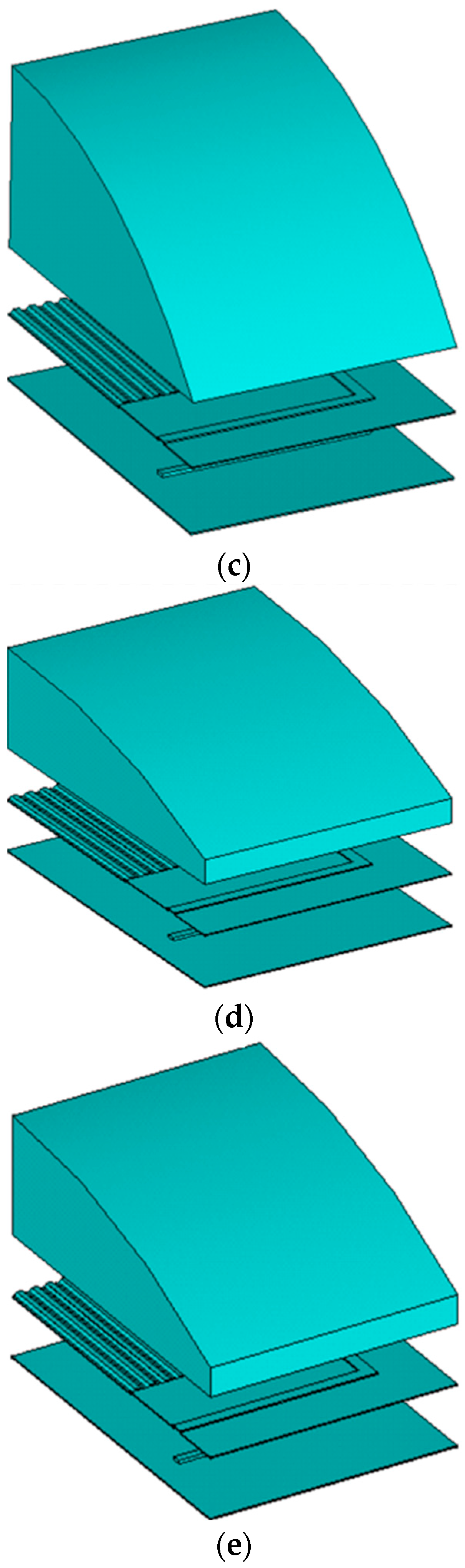
Five fuel cell stack models with different cross-sectional endplates are shown in Figure 5. The materials are shown in Table 1. According to the symmetry, the 1/4 models are developed to reduce the calculation resource and improve the calculation efficiency. In the discretization of the model, the sealant, bipolar plate, MEA, and endplates all use the Solid95 mesh. The mesh shape is tetrahedral, and the free mesh is adopted. The contact between the MEA and the sealant is bonded. The contact behavior between the bipolar plate and the endplate is also bonded to simulate the boundary condition after the assembly of the fuel cell stack. The contact behavior between the sealant and the bipolar plate and MEA and the bipolar plate is frictional.

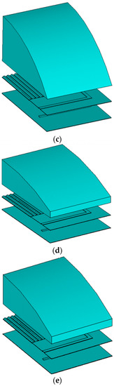
Figure 5.
Five fuel cell stack models with different endplates: (a) Rectangle; (b) round; (c) parabola; (d) rectangle + round; (e) rectangle + parabola.

Table 1.
Materials used in the simulation.
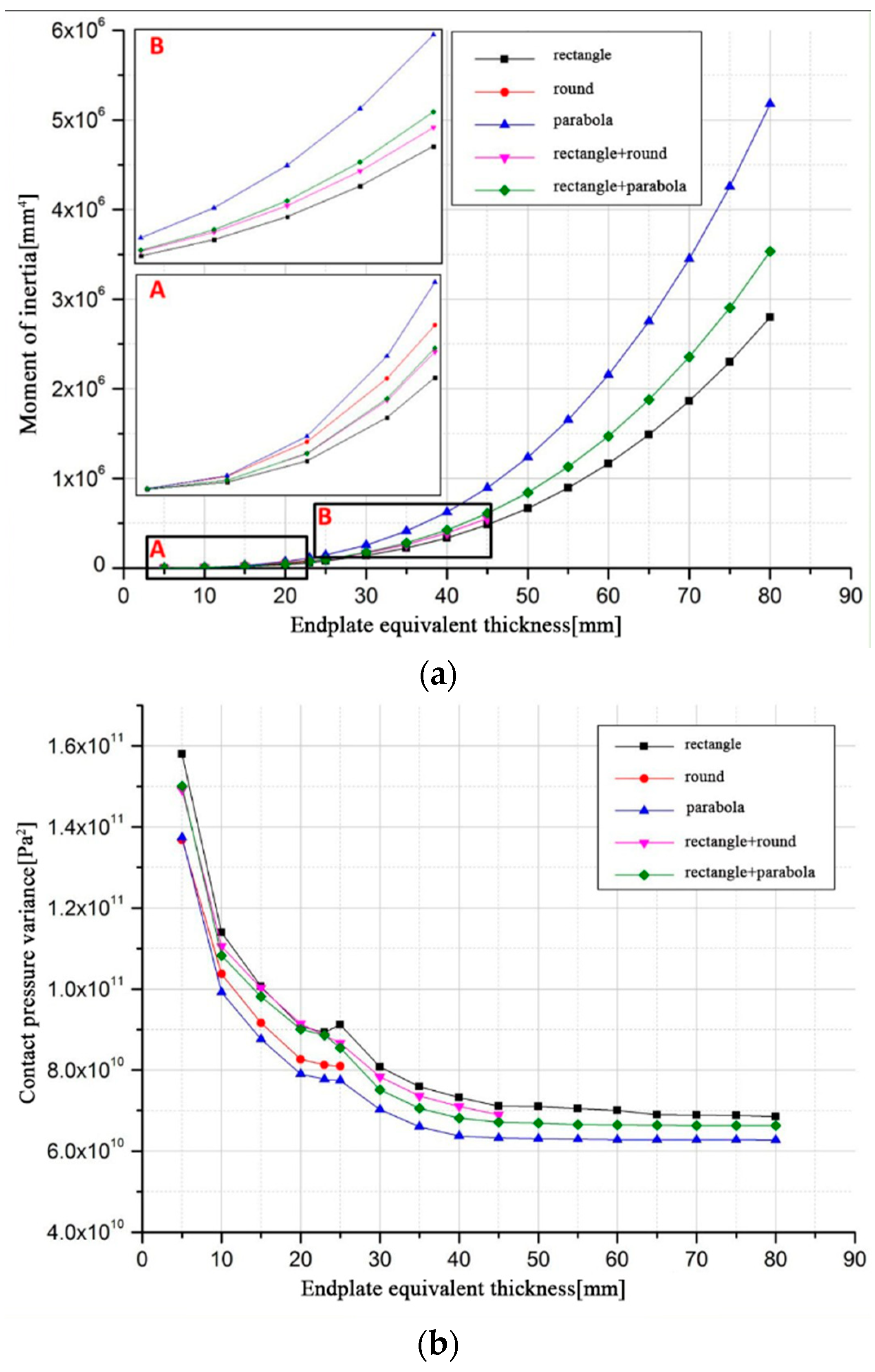
Based on the models, the moments of inertia and the contact pressure distribution with five cross-sectional shapes are analyzed and the numerical results are shown in Figure 6. Figure 6a shows the moments of inertia with increasing equivalent thickness for different cross-sectional shapes of the endplates. For the same thickness and area of the endplate, the parabolic cross-section has the maximum moment of inertia, and then there is the “rectangular + parabola” cross-section, which corresponds with the analytical results as presented. Furthermore, with an endplate thickness of 80 mm, the moment of inertia of the parabolic cross-section is 85.71% higher than the rectangular cross-section.
Figure 6.
The moment of inertia and contact pressure variance of five different cross-sectional endplates: (a) Moment of inertia; (b) contact pressure variance.
Figure 6b shows the uniformity of contact pressure distribution between the MEA and bipolar plate with increasing equivalent thickness for different cross-sectional shapes. The contact pressure variance is defined as the value of standard deviation divided by the mean, which can be used to indicate uniformity. The smaller the contact pressure variance, the better the uniformity. For the parabola cross-section of the endplate, the contact pressure variance is minimum, and then there is the “rectangular + parabola”, which corresponds with the analytical results as presented. With an endplate thickness of 80 mm, the contact pressure variance of the parabola cross-sectional shape is 6.15% less than the rectangular shape.
With the endplate equivalent thickness increasing, the moment of inertia for different shapes increases greatly. When the thickness is larger than 40 mm, the contact pressure variance almost remains the same although the moment of inertia increases. The reason is that when the endplate is thick enough, the thickness is not an important factor for uniformity. To further decrease the contact pressure variance, other factors such as the material and the position of the belt should be considered.
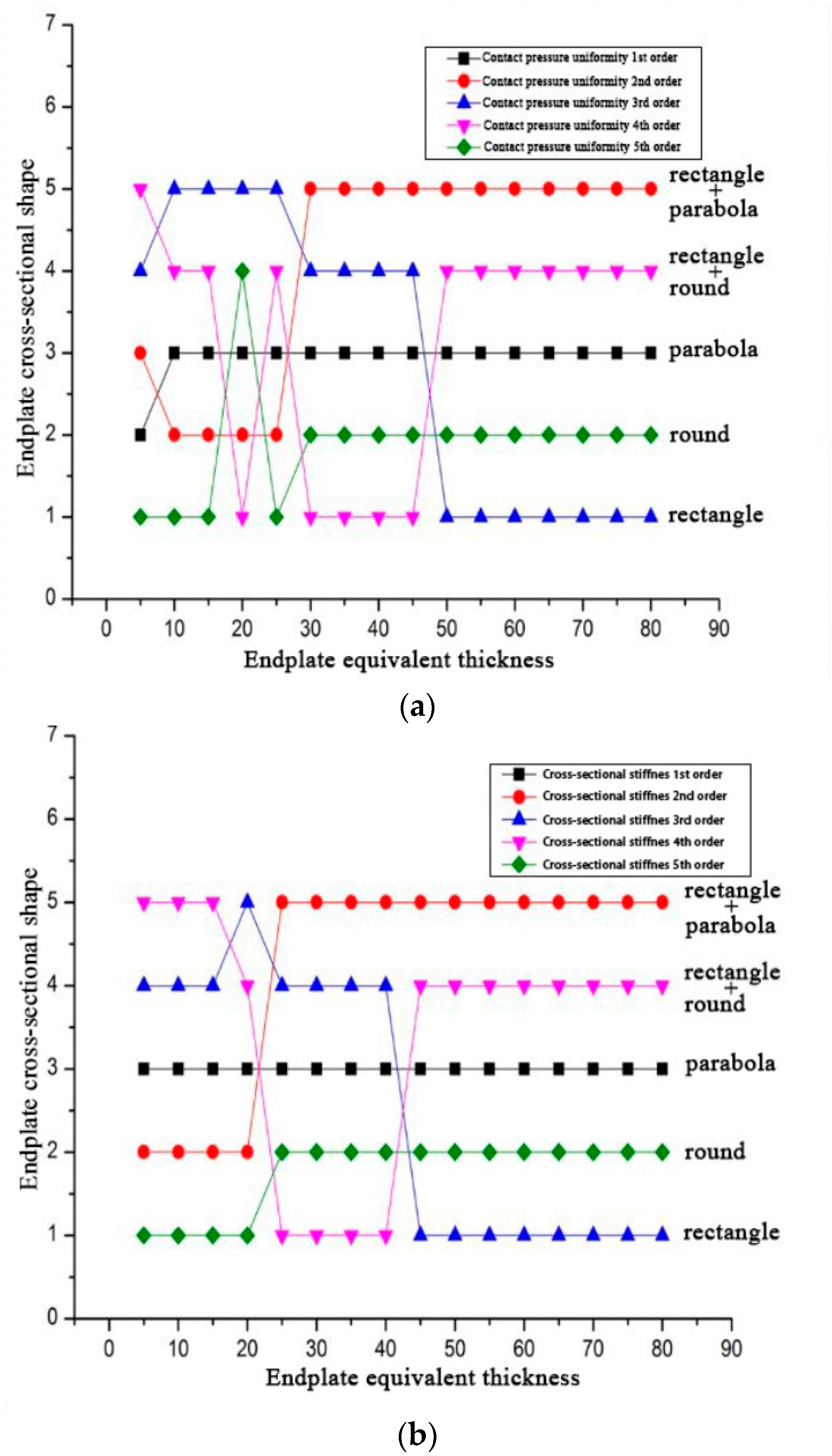
Therefore, it can be found that with the same cross-sectional area, the endplates with different cross-sectional shapes have different moments of inertia, which lead to the different uniformity of the contact pressure inside the fuel cell stack. The larger the moment of inertia of the endplate, the more uniform the contact pressure distribution. The contact pressure variance of each shape is in the opposite order of the moment of inertia. The order is further analyzed, as shown in Figure 7.
Figure 7.
Comparison of different orders: (a) Ordered by contact pressure uniformity; (b) ordered by cross-sectional stiffness.
In Figure 7a, five endplate cross-sectional shapes are ordered by contact pressure uniformity. The shape in the first order of the contact pressure uniformity is the one with the minimum contact pressure variance, which means the uniformity is the best among all shapes. In Figure 7b, five endplate cross-sectional shapes are ordered by the cross-sectional stiffness. The shape in the first order of cross-sectional stiffness is the one with the maximum moment of inertia.
These trends of each cross-sectional shapes as shown in Figure 7a,b are almost the same, especially when the equivalent thickness is larger than 30 mm. When the thickness is less than 30 mm, there is a certain difference due to the influence of the existing installation grooves of the steel belts on the endplate. When the equivalent thickness of the endplate is large, the effect of the installation groove of the steel belts will gradually decrease, and then tends to be consistent.
From the presented analysis, the results of the analytical study regarding the moment of inertia and the numerical results of FEM models correspond with each other. In particular, in the field of the optimal cross-sectional shape study of the endplate, the analytical study is recommended thanks to the reliability and the economic calculation cost for a large fuel cell stack.
4. Discussion and Conclusions
The uniform contact pressure is crucial to the performance of a PEMFC stack. The deflection of the endplate will significantly cause the inhomogeneity of contact pressure. Therefore, the endplate should have enough stiffness to minimize its deflection. A cross-sectional shape with a high moment of inertia is desirable to improve the endplate bending stiffness.
Firstly, five typical different cross-sectional shapes of the endplates were proposed, and their moments of inertia were introduced and analyzed based on a theoretical method.
Then, the thickness and width of the endplate in a wide dimensional size were considered in the calculation of the moment of inertia. For the different cross-sectional shapes of the endplate, the proportion of the maximum moments of inertia with the different thicknesses and widths was different. The “rectangular + parabola” endplate is advantageous in the wide dimensional size of the endplate. The distribution matrix is therefore developed so that the optimal shape can be selected more easily and quickly in engineering design.
Finally, the 3D FEM models were developed to validate the analytical study. The cross-sectional shape did not influence the contact pressure unevenness along the stack assembly direction, while it had an important influence on the uniformity of contact pressure distribution on the multi-contact interface. The results of the analytical study and the FEM were in high agreement. With a larger moment of inertia of the endplate, the uniformity of the contact pressure is better.
This study confirms that we could adopt this effective theoretical method for the optimal cross-sectional shape design and evaluate the fuel cell endplate design, which will be economical regarding the huge calculation resource and the convergence difficulty of using FEM for a large fuel cell stack.
Author Contributions
Conceptualization, Z.Z. and J.Z.; methodology, Z.Z. and Y.S.; software, J.Z. and Y.S.; validation, Z.Z. and J.Z.; resources, Z.Z.; writing—original draft preparation, Z.Z. and J.Z.; writing—review and editing, Z.Z.; funding acquisition, Z.Z. and T.Z. All authors have read and agreed to the published version of the manuscript.
Funding
This research was funded by the Natural Science Foundation of Shanghai, grant number 22ZR1466800.
Institutional Review Board Statement
Not applicable.
Informed Consent Statement
Not applicable.
Data Availability Statement
Not applicable.
Conflicts of Interest
The authors declare no conflict of interest.
References
- Wang, Y.; Yuan, H.; Martinez, A.; Hong, P.; Xu, H.; Bockmillera, F.R. Polymer Electrolyte Membrane Fuel Cell and Hydrogen Station Network for Automobiles: Status, Technology, and Perspectives. Adv. Appl. Energy 2021, 2, 100011. [Google Scholar] [CrossRef]
- Xu, X.; Zhao, J.; Zhao, J.; Shi, K.; Dong, P.; Wang, S.; Liu, Y.; Guo, W.; Liu, Z. Comparative study on fuel saving potential of series-parallel hybrid transmission and series hybrid transmission. Energy Convers. Manag. 2022, 252, 114970. [Google Scholar] [CrossRef]
- Hu, D.; Wang, Y.; Li, J.; Yang, Q.; Wang, J. Investigation of optimal operating temperature for the PEMFC and its tracking control for energy saving in vehicle applications. Energy Convers. Manag. 2021, 249, 114841. [Google Scholar] [CrossRef]
- Zhou, J.; Feng, C.; Su, Q.; Jiang, S.; Fan, Z.; Ruan, J.; Sun, S.; Hu, L. The Multi-objective Optimization of Powertrain Design and Energy Manegement Strategy for Fuel Cell-Battery Hybrid Electric Vehicle. Sustainability 2022, 14, 6320. [Google Scholar] [CrossRef]
- Luo, M.; Zhang, J.; Zhang, C.; Chin, C.S.; Ran, H.; Fan, M.; Du, K.; Shuai, Q. Cold start investigation of fuel cell vehicles with coolant preheating strategy. Appl. Therm. Eng. 2022, 201, 117816. [Google Scholar] [CrossRef]
- Zhang, C.; Cao, X.; Bujlo, P.; Chen, B.; Zhang, X.; Sheng, X.; Liang, C. Review on the safety analysis and protection strategies of fast filling hydrogen storage system for fuel cell vehicle application. J. Energy Storage 2022, 45, 103451. [Google Scholar] [CrossRef]
- Millichamp, J.; Mason, T.J.; Neville, T.P.; Rajalakshmi, N.; Jervis, R.; Shearing, P.R.; Brett, D.J.L. Mechanisms and effects of mechanical compression and dimensional change in polymer electrolyte fuel cells—A review. J. Power Source 2015, 284, 305–320. [Google Scholar] [CrossRef]
- Shi, Q.; Feng, C.; Ming, P.; Tang, F.; Zhang, C. Compressive stress and its impact on the gas diffusion layer: A review. Int. J. Hydrogen Energy 2022, 47, 3994–4009. [Google Scholar] [CrossRef]
- Peng, L.; Shao, H.; Qiu, D.; Yi, P.; Lai, X. Investigation of the non-uniform distribution of current density in commercial-size proton exchange membrane fuel cells. J. Power Source 2020, 453, 227836. [Google Scholar] [CrossRef]
- Park, T.; Chang, I.; Jung, J.H.; Lee, H.B.; Ko, S.H.; O’Hayre, R.; Yoo, S.J.; Cha, S.W. Effect of assembly pressure on the performance of a bendable polymer electrolyte fuel cell based on a silver nanowire current collector. Energy 2017, 134, 412. [Google Scholar] [CrossRef]
- Weng, L.F.; Jhuang, J.W.; Bhavanari, M.; Lee, K.R.; Lai, Y.H.; Tseng, C.J. Effects of assembling method and force on the performance of proton Exchange membrane fuel cells with metal foam flow field. Int. J. Energy Res. 2020, 44, 9707–9713. [Google Scholar] [CrossRef]
- Zhang, T.; Li, J.; Li, Q.; Yu, M.; Sun, H. Combination effects of flow field structure and assembly force on performance of high temperature proton exchange membrane fuel cells. Int. J. Energy Res. 2021, 45, 7903–7917. [Google Scholar] [CrossRef]
- Han, I.S.; Park, S.K.; Chung, C.B. Effect of gas diffusion layer compression on the polarization curves of a polymer electrolyte membrane fuel cell: Analysis using a polarization curve-fitting model. Korean J. Chem. Eng. 2016, 33, 3121. [Google Scholar] [CrossRef]
- Bhosale, A.C.; Rengaswamy, R. Interfacial contact resistance in polymer electrolyte membrane fuel cells: Recent developments and challenges. Renew. Sustain. Energy Rev. 2019, 115, 109351. [Google Scholar] [CrossRef]
- Shinde, U.; Koorate, P.K. Numerical investigation on the sensitivity of endplate design and gas diffusion material models in quantifying localized interface and bulk electrical resistance. Int. J. Hydrogen Energy 2021, 46, 17358–17373. [Google Scholar] [CrossRef]
- Chen, C.Y.; Su, S.C. Effects of assembly torque on a proton exchange membrane fuel cell with stamped metallic bipolar plates. Energy 2018, 159, 440–447. [Google Scholar] [CrossRef]
- Habibnia, M.; Shirkhani, M.; Tamami, P.G. Optimization of proton exchange membrane fuel cell’s end plates. SN Appl. Sci. 2020, 2, 1380. [Google Scholar] [CrossRef]
- Asghari, S.; Shahsamandi, M.H.; Khorasani, M.R.A. Design and manufacturing of end plates of a 5kW PEM fuel cell. Int. J. Hydrogen Energy 2010, 35, 9291–9297. [Google Scholar] [CrossRef]
- Lin, P.; Zhou, P.; Wu, C.W. A high efficient assembly technique for large proton exchange membrane fuel cell stacks: Part II. Applications. J. Power Source 2009, 195, 1383–1392. [Google Scholar] [CrossRef]
- Lin, P.; Zhou, P.; Wu, C.W. Multi-objective topology optimization of end plates of proton exchange membrane fuel cell stacks. J. Power Source 2011, 196, 1222–1228. [Google Scholar] [CrossRef]
- Carral, C.; Charvin, N.; Trouve, H.; Mele, P. An experimental analysis of PEMFC stack assembly using strain gage sensors. Int. J. Hydrogen Energy 2014, 39, 4493. [Google Scholar] [CrossRef]
- Zhang, Z.; Shang, Y.; Zhang, J. Optimization of the size and shape of the end plate of the fuel cell stack with steel straps. J. Tongji Univ. (Nat. Sci. Ed.) 2017, 45, 575–581. (In Chinese) [Google Scholar]
- Liu, J.; Tan, J.; Yang, W.; Li, C.; Wang, C. Better electrochemical performance of PEMFC under a novel pneumatic clamping mechanism. Energy 2021, 229, 120796. [Google Scholar] [CrossRef]
- Alizadeh, E.; Ghadimi, M.; Barzegari, M.M.; Momenifar, M.; Saadat, S.H.M. Development of contact pressure distribution of PEM fuel cell’s MEA using novel clamping mechanism. Energy 2017, 131, 92–97. [Google Scholar] [CrossRef]
- Qiu, Y.; Wu, P.; Miao, T.; Liang, J.; Jiao, K.; Li, T.; Lin, J.; Zhang, J. An Intelligent Approach for Contact Pressure Optimization of PEM Fuel Cell Gas Diffusion Layers. Appl. Sci. 2020, 10, 4194. [Google Scholar] [CrossRef]
- Chang, I.; Park, T.; Lee, J.; Lee, H.B.; Ko, S.H.; Cha, S.W. Flexible fuel cell using stiffness controlled endplate. Int. J. Hydrogen Energy 2016, 41, 6013. [Google Scholar] [CrossRef]
- Wei, M.Y. Optimum Design of End Plate for Steel Tape Encapsulated Fuel Cell. Master’s Thesis, Dalian University of Technology, Dalian, China, 2016. (In Chinese). [Google Scholar]
- Zhang, Z.; Zhang, J.; Zhang, T. Endplate Design and Topology Optimization of Fuel Cell Stack Clamped with Bolts. Sustainability 2022, 14, 4730. [Google Scholar] [CrossRef]
- Jiang, H.N. Research on the Optimization Design and Impact Resistance of Proton Exchange Membrane Fuel Cell End Plates. Master’s Thesis, Dalian University of Technology, Dalian, China, 2014. (In Chinese). [Google Scholar]
- Liu, H.W. Mechanics of Materials, 5th ed.; Higher Education Press: Beijing, China, 2011. (In Chinese) [Google Scholar]

Publisher’s Note: MDPI stays neutral with regard to jurisdictional claims in published maps and institutional affiliations. |
© 2022 by the authors. Licensee MDPI, Basel, Switzerland. This article is an open access article distributed under the terms and conditions of the Creative Commons Attribution (CC BY) license (https://creativecommons.org/licenses/by/4.0/).