Abstract
Renewable energy implementation in residential-scale grid-connected systems is already popular, and the growth of such systems is increasing every year. Grid-connected solar systems are relatively simple to install and operate; in addition, such power plants are relatively inexpensive compared to other renewable sources and grid-connection options. However, most residential grid-connected system owners believe that they will become independent from a distribution system operator (DSO) once a renewable energy source (RES) becomes available. As a rule, after installation, without DSOs, grid-connected systems are typically shut down due to a faulty grid, despite RES availability; therefore, such RES grid-connected system owners at later phases aim to become at least partially independent of DSOs. After such a change, the importance of developing a grid-tied inverter connection to an off-grid system will increase. While developing such a system connection the main issue analyzed in this paper is to control the excess power without affecting the accumulated energy levels in a system. As a result, a solution for such a system structure is presented with its main advantage to control excess power without affecting the accumulated energy level.
1. Introduction
The topic of climate change is becoming more sensitive each year, and a growing amount of attention has been devoted to renewables that could drive the world’s energy supply. In this way, renewable energy sources (RESs) are being used on a larger and wider scale every day [1]. Small electricity consumers have a choice of generating electricity by themselves, and as electricity market prices rise and fluctuate [2] unpredictably, they become cost efficient even without subsidies. Becoming a prosumer is even more convenient if the local utility network is not stable. Recently, the number of consumers installing RESs has increased exponentially [3], but the majority of new residential-scale installations are prosumers with grid-connected systems. Taking small residential power plants into consideration, it is believed that after RES installation, there will be no subsequent electricity shortage as long as the RES is available, even if the utility grid is not available. However, after installing a grid-connected system, it is usually realized that if the utility grid is off, the RES and its grid-tied inverter [4] are switched off as well due to an under-voltage requirement.
In most cases, the social responsibility related to considering environmental change as a reason for investing in RES is a secondary priority. In addition to all global environmental change [5], the majority of consumers are trying to install the system considering the best economical and financial solution to reduce the investment and payback time of the installed system, which usually is the primary priority. There is a possibility of having hybrid, battery or back-up ready inverters [6] with different storage technologies [7] and different penetration levels in batteries and renewables [8,9,10]; if such a configuration is chosen in the first place, there will be no issues with that connection type when a system upgrade to off-grid is needed in the future. However, this is not the most beneficial price-based solution; the cheaper solution is a grid-connected system with a grid-tied inverter and photovoltaic panels [11,12]. Due to the need for uninterruptable power and the independency of DSO, the next step for developing grid-connected systems involves an upgrade to off-grid systems with a utility grid only as a reserve generator. This article is an overview of the issues and possible solutions for the scenario in which a residential-scale grid-tied inverter with no possibility of controlling its generating power is connected to an off-grid system. The experimental prototype device is presented, which adopts the grid-tied inverter to an off-grid system fulfilling the main goal of controlling the excess power without affecting the off-grid system’s battery state of charge (SOC) level. All other types of inverters, to the best of the authors’ knowledge, have no issues with connecting to an off-grid system, and these cases are not included in the article.
Because the prosumer’s choice is based on cost-saving when installing the grid-connected system in the first place, it will likely be necessary to maintain a currently owned grid-tied inverter in a new system that is being designed; again, the purpose of this is to save expenses. The main issue, as described in more detail below in Section 2, is the excess power and how to control it without affecting the system’s battery SOC, a few alternative types of possible solutions are given in Table 1.

Table 1.
Excess power control options.
In Table 1, excess power control options are presented according to the main comparison topics: non-affected battery SOC level; the implementation of such a control type versatility; and whenever excess power utilization is ensured. Off-grid system reserve power depends on the accumulated energy, and when controlling the excess power, it is important not to affect the accumulated energy quantity; therefore, this comparative is added to the table. As a simplified example, excess power could be only 0.1 kW, but if the additional load which utilizes the excess power is 2 kW, the difference will have to be covered by batteries, which will lead to a negative effect on battery SOC level. Implementation versatility is selected as one of the comparative subjects to compare the power control options in terms of how easy it is to install or adopt to different systems. Therefore, the solutions presented in Table 1 are analyzed as follows:
- Thermal storage and dump load—both options ensure excess power control at any time. Thermal storage, either controlled based on cold or heat [13] during peak times [14,15], can eliminate the excess power issues. On the other hand, it might also affect the comfort of consumers [16]; furthermore, this is not a straightforward installation in all cases. A similar scenario for the use of excess power is the dump load [34]; in this case, the versatility is high because of the simplicity of the system [35]. Nevertheless, the excess power can be controlled in the designed steps, which leads to a negative effect on the accumulated energy [33] (SOC level);
- Pump storage, V2G/G2V, and fuel cell—pump storage is not a versatile solution in the first place [18], and the control of the variable pump storage power is available; however, such versatile availability is compatible only for large-scale solutions [17] and is complicated for residential solutions [19,20]. Fuel cells have a low cycle efficiency [31] and complicated versatility [28,30], possibly because of the lack of solution supply for such a system. The G2V solution is a versatile and simple option for controlling excess power implementation while only scheduling with fixed power [29]; however, in this case, the off-grid systems battery SOC level is affected. Controlling the EV’s charging power in a grid-connected system [32,33] is a simple solution, but implementing the same in an off-grid system is not a versatile option. These options, especially V2G/G2V, for controlling the excess power expand the quantity of accumulated energy but do not solve the excess power issue in an off-grid system; nevertheless, the versatility of such an implementation would not be achieved in all cases;
- Scheduling—this is a versatile solution to control the excess energy in an off-grid system or to simply control the demand [21,27] in a timeline by using the predicted [22] excess energy, but consumer comfort [25,26] is affected and a system must be smart with a one-of-a-kind control algorithm [23,24]. Therefore, this is not a versatile solution and the accumulated energy might be affected anyway;
- Inverter control—is a solution that would not affect the accumulated energy [40,41]; it would always control the excess power [37], but every inverter brand excess power control device would be different, as the control algorithm would be different [37,39]. This means that this option is not a versatile solution.
- Variable average power load (VAPL)—experimental prototype is suggested by the authors of this article, as described in Section 4. The experimental prototype utilizes the excess power while not affecting the systems battery SOC level and, on the other hand, is a versatile solution to implement in any off-grid system, or any grid-tied inverter.
The off-grid system is dependent on the accumulated energy level, and a solution for grid-tied inverter connection to such a system, which would be convenient, would have no effect on the battery SOC level, be easy to use, and be easy to implement (versatile), is not found. Therefore, the main motivation and aim of this research is to find and adopt a new solution which would fulfill the requirement of controlling the excess power in an off-grid system, caused by the grid-tied inverter without affecting the battery SOC level.
In Section 2, the excess power issue is analyzed and underlined. Section 3 describes the test system’s structure—an off-grid system in combination with RES connected via a grid-tied inverter. In Section 4, an experimental VAPL prototype device is presented. In Section 5 the test results of VAPL device are analyzed. In Section 6 and Section 7, the results are revised and summarized.
2. Issues Involved in Connecting a RES to an Off-Grid System via a Grid-Tied Inverter
The grid-tied inverter control algorithm is programmed in such a way to convert all the possible direct current (DC) power to alternating current (AC) power. Therefore, when the inverter is connected to a distribution system operator (DSO) (utility) grid, the inverter exports all the excess power to the grid. However, when such an inverter is connected to an off-grid or island system, the supply and demand power balance dramatically changes and becomes a major problem.
The experimental off-grid system described in Section 3 is unique, although the working principle and issues are the same for all off-grid or island systems; the supply and demand power balance issue is relevant for all grids. The RES in an off-grid system should be designed and connected via off-grid type inverters; in this way, when the consumption is low and the RES generates power, off-grid type inverters control their producing power according to the off-grid system power demand. Such a design is not efficient (because the excess power is spilled), but it works in balanced harmony with the other system components. As an example, in Figure 1, the off-grid system with RES connected to the system via off-grid type inverter operation is shown. Figure 1 visualizes a case when excess power is detected, at the detection of excess power off-grid type inverter limits its power production, even when irradiance (as well as the possible to produce power) is not changed.
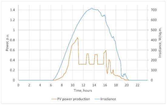
Figure 1.
RES connected to an off-grid system via an off-grid type inverter.
In the same system, simply adding a grid-tied inverter creates a completely different situation. Under the same conditions in the microgrid system, the consumption is low, the RESs generate power, and their inverter is the grid-tied type; therefore, the constant switching of the inverter on and off occurs because of a supply and demand power mismatch in a system power balance. Figure 2 illustrates the switching periods, in which the period time is dependent on the system demand level. To illustrate the constant on and off switching, the time frame in Figure 2 is reduced because the constant switching is monitored.
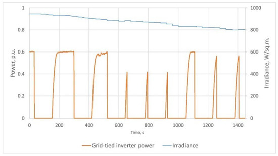
Figure 2.
RES connected to an off-grid system via a grid-tied type inverter.
The off-grid system with RES connected via a grid-tied inverter leads to unacceptable operating parameters. Not only does the grid-tied inverter switch on and off simultaneously as long as the excess power is monitored, but the quality of electricity is also affected and is usually not within the EN 50160 standard ranges.
As illustrated in Figure 2, the grid-tied inverter switches on and off as fast as the grid-tied inverter is capable of restarting after grid failure error. During the measurements, it is observed that the on and off switching lasts as long as excess power is detected; when excess power is not detected, the system works in balance. To emphasize this issue and understand it in detail, the time frame is expanded to monitor the time when excess power is detected and the switching is analyzed in detail, as shown in Figure 3.
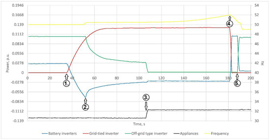
Figure 3.
A RES connected to an off-grid system via a grid-tied type inverter, where the problem is shown in detail.
The main events, as illustrated in Figure 3, are:
- In the first few seconds, the grid-tied inverter starts up and does not produce any power. Off-grid type and battery inverters supply the appliances until the grid-tied inverter starts. After the start of the grid-tied inverter, the off-grid inverter still produces as much power as possible, and the battery inverters charge the batteries with all the excess power until reaching the start of the battery float-charge mode;
- The grid-tied inverter produces as much power as possible. Off-grid inverters limit their power to balance the demand and supply. Battery inverters reduce the charging current due to the float-charge mode. The operation is balanced until the power of the load decreases;
- The power demand drops slightly. The off-grid type inverter stops producing power. The grid-tied inverter still produces as much as possible. Battery inverters charge the batteries with all the excess power, which is more than that of the battery float-charge mode. Because of the excess power, the frequency starts to rise in a system above 50.75 Hz. The off-grid inverter has a programmed upper limit of frequency where its power is reduced to 0 if the frequency reaches 50.75 Hz or above. Because of this excess power, the frequency rises until it reaches 52 Hz, which is the maximum allowed frequency set limit for the grid-tied inverter;
- The grid-tied inverter switches off due to grid-over frequency error. The battery inverters start to generate power simultaneously to supply the appliances. The off-grid inverter does not yet start producing because the frequency is still higher than 50.75 Hz;
- The frequency drops below 50.75 Hz, and the off-grid inverter starts to produce power. Accordingly, battery inverters produce less in order to balance the demand and supply power. The grid-tied inverter switches off until grid failure is no longer detected, and a restart procedure is initialized. Therefore, the grid-tied inverter starts again, and switching repeats as long as excess power is still detected in the system.
For Steps 1 to 5, as shown in Figure 3, the switching continues repeating as long as the demand power rises or the renewables supply power drops. All appliances or other generating units that are connected to such an off-grid system suffer from a low-quality electricity supply; therefore, their operating conditions are also affected due to the excess power caused by the grid-tied inverter. Because of a fluctuating RES and the excess power, supply and demand power balancing problems occur not only in an off-grid system but also in large electricity systems; with a sufficiently large penetration level of renewable power in a system, the same problem occurs on another scale.
The main problem of a grid-tied inverter connection to an off-grid system is a supply and demand power balance because the supply power via a grid-tied inverter cannot be limited or controlled. Furthermore, the solution for a grid-tied inverter supply power control is presented, which fulfils both goals by not affecting the battery SOC level and versatility.
3. Experimental Off-Grid System Structure
A microgrid with a peak power of 18 kW that is powerful enough to cover more than an annual household’s power demand was created. The experimental system consists of the equipment, the principal scheme of which is visualized in Figure 4.
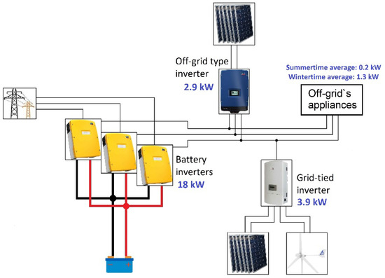
Figure 4.
Experimental off-grid system scheme.
The described off-grid system consists of the equipment listed in Table 2 and supplies electricity for the renewable energy sources laboratory at the Kaunas University of Technology Department of Electric Power Systems, located in Lithuania.
Table 2.
Experimental system equipment list.
The sunniest period of time in Lithuania’s region is from the beginning of June through the end of August; in addition, due to holidays, the consumption of the laboratory is at its minimum during this time. On the other hand, during the winter, the consumption is at its maximum because of the need for electrical heating. Due to the highest RES supply during summer coincides with the lowest demand, the experimental off-grid system faces excess power in the summer and a shortage of electricity in winter. Figure 5 is used to visualize the demand of solar and wind power potential distribution throughout the year.
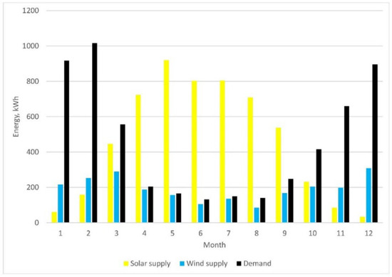
Figure 5.
Experimental off-grid systems monthly supply and demand balances.
The experimental off-grid usable battery energy is:
where Vnom is the nominal battery voltage [V] and C10 is the nominal battery capacity [Ah] when the discharge time is 10 h and the coefficient of 0.6 is the value of the acceptable discharge level because of valve-regulated lead-acid (VRLA) batteries used in the system. The real and usable energy of batteries is calculated to be 3.8 kWh, which is not a significant number compared to a nominal system power of 18 kW but is enough to balance the peaks in the RES supply and demand power.
Eusable = Vnom × C10 × 0.6,
Therefore, considering the battery capacity, the autonomous time for the experimental system is calculated. During the summer, demand is at its minimum: the average power is only 195 W, and the usable battery energy can cover the demand for 19.5 h. Meanwhile, in winter, the battery capacity can cover the demand for only 2.9 h.
T = Eusable/Eavg,
The battery capacity for the experimental off-grid system sufficiently covers the needs in summer because even if no RES is available, the battery capacity would cover the demand for nearly 20 h. In winter, when heating is the main demand, battery capacity can cover the demand for nearly 3 h only. However, the battery discharges even faster in reality because the discharge time of 10 h C10 changes to nearly C3, and the capacity of 2–3 h of discharge time further decreases [42].
Low battery capacity means that the experimental off-grid system has more available energy than the batteries can handle during the summer, which leads to RES power spillage. However, in the winter, the battery capacity is too low to cover the demand needs, so the reserve generator must be used frequently. The microgrid’s usable battery energy capacity is small and designed to balance power peaks, but it fully meets the requirements for the grid-tied inverter to be tested in the off-grid system.
4. VAPL Experimental Prototype with a PWM Algorithm Implemented
The investigation of the constant switching issue based on the excess power in an off-grid suggests that a variable power load is needed to ensure the off-grid system power balance and stability when a grid-tied type inverter with RES is connected to it. A VAPL experimental prototype for the excess power disbalance problem that fulfils the versatility requirements and has no effect on the battery SOC level is created and tested in an experimental system. For experimental device simplicity, a single-level pulse width modulation (PWM) method is designed and implemented in a VAPL experimental prototype. The main task for the VAPL device is to control its demand power at a rate of excess power. For the VAPL experimental prototype, any load that would not be damaged as a result of high-speed permanent switching, for example, a boiler for water heating, thermal storage, etc., could be used.
The Atmega 328P programmable board is used to create a PWM and make a VAPL device. The Atmega 328P digital pins produce either 5 V (when HIGH is selected) or 0 V (when LOW is selected), and the output is a square wave signal. Therefore, the voltage is never between 0 and 5 V, but the 5 V time might change according to the need. The example duty cycles of the PWM signal are illustrated in Figure 6.
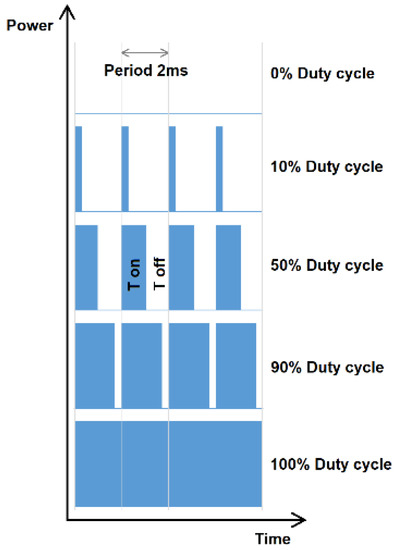
Figure 6.
Example duty cycles of PWM control.
If the ON and OFF times are changed fast enough, the average power of the load also changes. In this case, the program algorithm code is created, where the main calculated parameter is the duty cycle, representing the percentage of time when the signal is high (5 V) during the period.
For example, at a 50% duty cycle, a load of half-average power is achieved. A changing duty cycle that is dependent on the system’s frequency is created. The Atmega 328P programmable board has a built-in function of “analogWrite()”, which can be used to generate a PWM signal. The frequency of this generated signal for most of the output pins is approximately 490 Hz (with a period of approximately 2 ms), and a duty cycle value split from 0 to 255 using this function can be used:
- AnalogWrite(0) equals a 0% duty cycle signal;
- AnalogWrite(127) equals a 50% duty cycle signal;
- AnalogWrite(255) equals a 100% duty cycle signal.
Therefore, the power of a VAPL device can be controlled by a step of 0.4% of the initial power and controlled dependently by the amount of excess power to fulfil the no effect condition on the target battery SOC level. As already mentioned, an Atmega 328P programmable board is used to identify the excess power and to create a PWM control signal.
First, the excess power is identified. The 50 Hz system positive voltage wave of a period is converted to a square form signal wave by a transistor. Using the optocoupler transistor, the nonharmful square signal of the half sine wave is created. The programmable board measures the time when a wave signal is HIGH (ON) and the signal is LOW (OFF). With these measured times, the system frequency is calculated:
where f is the frequency in Hz, T is the period in s, and tON and tOFF are the signal HIGH and signal LOW times, respectively.
f = 1/T = 1/(tON + tOFF),
Second, the PWM value is generated. Depending on the measured period and calculated frequency in each phase of a three-phase system, the PWM duty cycle is calculated, and an average power might be achieved through various values. For the Atmega 328P programmable board to control the VAPL, the control algorithm code illustrated in Figure 7 is created. In this case, the versatility target of implementing a VAPL device for different systems with different primary loads as the VAPL load is fulfilled.
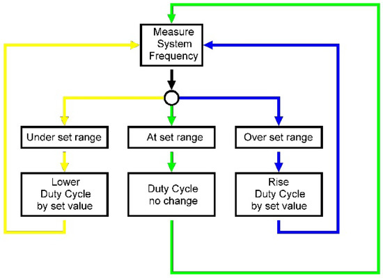
Figure 7.
VAPL experimental prototype control algorithm.
In an experimental off-grid system, the noncontrolled renewable source (RES connected via a grid-tied inverter) is a single phase, and the whole off-grid is a three-phase system. In the process of creating the VAPL device, a versatile device capable of controlling both single- and three-phase grid-tied inverter types was created, as illustrated in Figure 8.
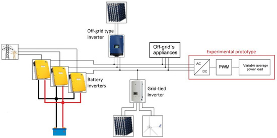
Figure 8.
Scheme of the VAPL experimental prototype connection to an off-grid system.
Because of the VAPL device idea, the PWM must complete a permanently high-speed switching of the rectified (in this case three-phase) voltage and current. The only requirement for such a device is to identify the highest possible excess power in a system and to select the primary load for the VAPL device that is at least slightly more powerful than the identified possible excess power. The prototype’s primary load resistance was calculated based on the maximum possible excess power in the system. The grid-tied inverter has two non-controllable RESs connected: a horizontal axis wind turbine (HAWT) of 1 kW of nominal power and solar panels with a peak power of 2.88 kWp. Therefore, in total, the system has 3.88 kW of noncontrolled peak power, which might be equal to the maximum excess power in various scenarios. The VAPL resistance is calculated as:
where Rmax is the VAPL optimal resistance [Ω], U is the rectified voltage [V], and Pmax is the maximum possible excess power [W].
Rmax = U/I = U × U/Pmax,
The experimental off-grid system has a 230/400 V three-phase system, and after the three-phase rectifier bridge, 620 VDC is achieved. The calculated Rmax of the VAPL device is 96.1 Ω and 6.45 A of current, and the total designed power of a device is 4.00 kW, which is enough to utilize the maximum possible excess power. The VAPL experimental prototype must be able to permanently switch 620 VDC and at least 6.5 A of current. Because of the voltages and currents, a VAPL device with an electric circuit scheme, as illustrated in Figure 9, is created. Energy dissipation is achieved through the created 97 Ω heater designed for maximum 5 kW electric power. In this scheme, there is a frequency-measuring loop, Atmega 328P programmable board, transistor driver, and power electronics loops.
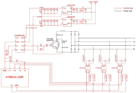
Figure 9.
VAPL experimental prototype scheme design.
5. Experimental Prototype Test Results
The testing of the VAPL experimental prototype was carried out in sunny day conditions when excess power could have been expected. A windy day with only 1 kW of available nominal power was foreseen to be insufficient to achieve excess power in the system. The test values were measured with five synchronized analyzers, and the power flow of each component was obtained simultaneously. As mentioned in Section 2, the main issue of such a grid-tied inverter connected to an off-grid system is the excess power caused by the grid-tied inverter, which is a destabilizing factor in the system.
During the period of excess power detection, the frequency rises, and the VAPL experimental prototype increases the duty cycle along with the average power of the primary load. Then, the frequency decreases the VAPL also reduces the duty cycle along with the average power of the primary load. To illustrate and describe the successful operation of VAPL in a system with detected excess power in detail, an enlarged time frame of a working system is shown in Figure 10.
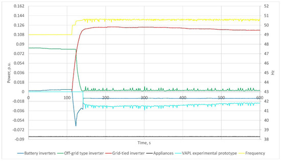
Figure 10.
Off-grid system with a grid-tied inverter and VAPL experimental prototype in use.
As shown in Figure 10, the off-grid system frequency is close to the set frequency of 50.75 Hz; the grid-tied inverter produces as much power as possible; the battery inverters charge the batteries in a float-charge mode; the off-grid capable inverter reduces its power to almost 0; and no more frequency rise or switching periods of the grid-tied inverter are observed. The VAPL experimental prototype has therefore been used to successfully demonstrate its dedicated task in such a system. The time lapse shown in Figure 10 is 600 s long to enlarge the time period when excess power is detected.
- At approximately the 100-s time stamp, the noncontrollable grid-tied inverter (red line) begins to produce power;
- A few seconds later, the off-grid type inverter (green line) reduces its power because the frequency (yellow line) reaches its operating set limit of 50.75 Hz;
- At approximately 140 s, the VAPL experimental prototype (cyan line) kicks into action;
- The entire time lapse is relatively short, and the battery inverters are in a float-charge mode; therefore, the battery SOC remains the same at 80%, representing the battery float-charge mode;
- Some frequency and power variation is monitored due to the control loop of the VAPL prototype device and the system reaction to the control loop step.
It is important to mention that each piece of equipment in the system frequency ranges must be set to work within a desired selectivity, including the battery inverters, grid-tied and off-grid inverters, and the VAPL prototype itself. Changing the frequency ranges of the equipment induces different system working scenarios.
During testing, few drawbacks were observed, such as an increase in the current and voltage harmonics, which changed the power quality in the system; and the VAPL prototype control loop and the system’s reaction to the change in power were found to slightly affect each other. However, such a problem might be reduced by adding filters to the design. Harmonics are not the main aim of this paper, furthermore, in the experimental off-grid system, there were no appliances that were sensitive to harmonics, so this issue was not studied deeply here, but the authors do not underestimate the issues; therefore, further research will be carried out regarding the drawbacks.
6. Discussion
A conceptual VAPL device was created in a straightforward way, but all the component inter-compatibility was developed in a complex way because each component affects each other. However, an experimental VAPL device prototype was created as a result. The device has demonstrated that it is capable of controlling excess energy without affecting the system reserve energy level. Despite it having achieved its designed goal, the device displayed a few drawbacks, such as increased current and voltage harmonics; therefore, further research will be carried out to analyze these drawbacks in combination with the testing of the system in different scale and design options.
7. Conclusions
The main issue analyzed in the article is the noncontrollable excess power in an off-grid system caused by the grid-tied inverter with RES connected to it. Excess power causes an increase in the frequency, which destabilizes the system’s supply and demand balance, and furthermore, affects the power quality in the system. Off-grid reserve energy depends on the battery SOC level; therefore, the main aim of the research was to find a versatile solution to control the excess power without affecting the accumulated energy level. A solution to this, a VAPL device, is presented, implemented in an experimental off-grid system, and tested. During the test, the VAPL device did not make any impact on the battery SOC level and additionally assured the power outage elimination. Due to the simplicity of the prototype, it is a versatile solution able to be implemented into various system designs or different power generation units.
Author Contributions
Conceptualization and supervision, T.D.; methodology, M.Z. and T.D.; software, M.Z.; validation, S.G.; formal analysis and funding acquisition, A.G.; investigation, J.B. and A.B.; resources, J.B. and A.B.; data curation, M.Z.; writing—original draft preparation, M.Z.; writing—review and editing, M.Z.; visualization, M.Z.; project administration, S.G. and A.J. All authors have read and agreed to the published version of the manuscript.
Funding
This research was funded by the European Economic Area (EEA) and Norway Financial Mechanism 2014–2021 under grant number EMP474.
Institutional Review Board Statement
Not applicable.
Informed Consent Statement
Not applicable.
Data Availability Statement
Not applicable.
Conflicts of Interest
The authors declare no conflict of interest. The funders had no role in the design of the study; in the collection, analyses, or interpretation of data; in the writing of the manuscript; or in the decision to publish the results.
References
- Our World in Data. Renewable Energy. 2020. Available online: https://ourworldindata.org/renewable-energy (accessed on 24 December 2020).
- Nord Pool Group Electricity Market Data. Available online: https://www.nordpoolgroup.com/Market-data1/Dayahead/Area-Prices/ALL1/Monthly/?view=table (accessed on 21 December 2021).
- Lithuanian DSO Statistics on Grid-Connected Prosumer Numbers in Lithuania. Available online: https://www.eso.lt/download/430131/gaminan%C4%8Di%C5%B3%20vartotoj%C5%B3%20prijungimo%20statistika%202021-10-22.pdf (accessed on 3 November 2020).
- EN 50549-1-2019. Requirements for Generating Plants to be Connected in Parallel with Distribution Networks—Part 1: Connection to a LV Distribution Network—Generating Plants up to and Including Type B. Available online: https://view.elaba.lt/standartai/view?search_from=primo&id=1312510 (accessed on 30 September 2022).
- NASA, Global Climate Change, Vital Signs of the Planet. Available online: https://climate.nasa.gov/vital-signs (accessed on 22 January 2022).
- Konneh, K.V.; Masrur, H.; Othman, M.L.; Wahab, N.I.A.; Hizam, H.; Islam, S.Z.; Crossley, P.; Senjyu, T. Optimal Design and Performance Analysis of a Hybrid Off-Grid Renewable Power System Considering Different Component Scheduling, PV Modules, and Solar Tracking Systems. IEEE Access 2021, 9, 64393–64413. [Google Scholar] [CrossRef]
- Hebner, R.E.; Davey, K.; Herbst, J.; Hall, D.; Hahne, J.; Surls, D.D.; Ouroua, A. Dynamic Load and Storage Integration. Proc. IEEE 2015, 103, 2344–2354. [Google Scholar] [CrossRef]
- Oladigbolu, J.O.; Ramli, M.A.M.; Al-Turki, Y.A. Feasibility Study and Comparative Analysis of Hybrid Renewable Power System for off-Grid Rural Electrification in a Typical Remote Village Located in Nigeria. IEEE Access 2020, 8, 171643–171663. [Google Scholar] [CrossRef]
- Ishraque, F.; Shezan, S.A.; Rashid, M.M.; Bhadra, A.B.; Hossain, A.; Chakrabortty, R.K.; Ryan, M.J.; Fahim, S.R.; Sarker, S.K.; Das, S.K. Techno-Economic and Power System Optimization of a Renewable Rich Islanded Microgrid Considering Different Dispatch Strategies. IEEE Access 2021, 9, 77325–77340. [Google Scholar] [CrossRef]
- Muh, E.; Tabet, F. Comparative analysis of hybrid renewable energy systems for off-grid applications in Southern Cameroons. Renew. Energy 2018, 135, 41–54. [Google Scholar] [CrossRef]
- Memodo Wholesaler, Inverter e-Shop. Available online: https://www.memodo-shop.com/inverters/ (accessed on 23 January 2022).
- Solarity, S.R.O. Inverter e-Shop. Available online: https://solarity.cz/products/inverters/ (accessed on 23 January 2022).
- Lu, N.; Vanouni, M. Passive energy storage using distributed electric loads with thermal storage. J. Mod. Power Syst. Clean Energy 2013, 1, 264–274. [Google Scholar] [CrossRef]
- Tasdighi, M.; Ghasemi, H.; Rahimi-Kian, A. Residential Microgrid Scheduling Based on Smart Meters Data and Temperature Dependent Thermal Load Modeling. IEEE Trans. Smart Grid 2013, 5, 349–357. [Google Scholar] [CrossRef]
- Tahir, M.F.; Haoyong, C.; Mehmood, K.; Ali, N.; Bhutto, J.A. Integrated Energy System Modeling of China for 2020 by Incorporating Demand Response, Heat Pump and Thermal Storage. IEEE Access 2019, 7, 40095–40108. [Google Scholar] [CrossRef]
- Anvari-Moghaddam, A.; Monsef, H.; Rahimi-Kian, A. Optimal Smart Home Energy Management Considering Energy Saving and a Comfortable Lifestyle. IEEE Trans. Smart Grid 2014, 6, 324–332. [Google Scholar] [CrossRef]
- Nirmal, M.C.M.; Sruthi, M.; Jayaprakash, P. Control of a Pumped Hydro Storage Power Plant Supported Solar PV Generation System for Grid-Side Energy Management. In Proceedings of the 2021 IEEE 4th International Conference on Computing, Power and Communication Technologies (GUCON), Kuala Lumpur, Malaysia, 24–26 September 2021; pp. 1–6. [Google Scholar] [CrossRef]
- Abdalla, S.M.; Saad, S.M.; El Naily, N.; Bukra, O.A. Seawater Pumped Hydro Energy Storage in Libya Part I: Location, Design and Calculations. In Proceedings of the 2021 IEEE 1st International Maghreb Meeting of the Conference on Sciences and Techniques of Automatic Control and Computer Engineering MI-STA, Tripoli, Libya, 25–27 May 2021; pp. 181–186. [Google Scholar] [CrossRef]
- Black, M.; Strbac, G. Value of Bulk Energy Storage for Managing Wind Power Fluctuations. IEEE Trans. Energy Convers. 2007, 22, 197–205. [Google Scholar] [CrossRef]
- Tahir, M.F.; Haoyong, C.; Khan, A.; Javed, M.S.; Laraik, N.A.; Mehmood, K. Optimizing Size of Variable Renewable Energy Sources by Incorporating Energy Storage and Demand Response. IEEE Access 2019, 7, 103115–103126. [Google Scholar] [CrossRef]
- Nayanatara, C.; Divya, S.; Mahalakshmi, E. Micro-Grid Management Strategy with the Integration of Renewable Energy Using IoT. In Proceedings of the 2018 International Conference on Computation of Power, Energy, Information and Communication (ICCPEIC), Chennai, India, 28–29 March 2018; pp. 160–165. [Google Scholar] [CrossRef]
- Bao, Z.; Qiu, W.; Wu, L.; Zhai, F.; Xu, W.; Li, B.; Li, Z. Optimal Multi-Timescale Demand Side Scheduling Considering Dynamic Scenarios of Electricity Demand. IEEE Trans. Smart Grid 2018, 10, 2428–2439. [Google Scholar] [CrossRef]
- Karapetyan, A.; Khonji, M.; Chau, S.C.-K.; Elbassioni, K.; Zeineldin, H.H.; El-Fouly, T.H.; Al-Durra, A. A Competitive Scheduling Algorithm for Online Demand Response in Islanded Microgrids. IEEE Trans. Power Syst. 2020, 36, 3430–3440. [Google Scholar] [CrossRef]
- Koutsopoulos, I.; Tassiulas, L. Optimal Control Policies for Power Demand Scheduling in the Smart Grid. IEEE J. Sel. Areas Commun. 2012, 30, 1049–1060. [Google Scholar] [CrossRef]
- Qayyum, F.A.; Naeem, M.; Khwaja, A.S.; Anpalagan, A.; Guan, L.; Venkatesh, B. Appliance Scheduling Optimization in Smart Home Networks. IEEE Access 2015, 3, 2176–2190. [Google Scholar] [CrossRef]
- Li, D.; Jayaweera, S.K. Distributed Smart-Home Decision-Making in a Hierarchical Interactive Smart Grid Architecture. IEEE Trans. Parallel Distrib. Syst. 2014, 26, 75–84. [Google Scholar] [CrossRef]
- Latif, A.; Paul, M.; Das, D.C.; Hussain, S.M.S.; Ustun, T.S. Price Based Demand Response for Optimal Frequency Stabilization in ORC Solar Thermal Based Isolated Hybrid Microgrid under Salp Swarm Technique. Electronics 2020, 9, 2209. [Google Scholar] [CrossRef]
- Sanjari, M.J.; Karami, H.; Gooi, H.B. Analytical Rule-Based Approach to Online Optimal Control of Smart Residential Energy System. IEEE Trans. Ind. Inform. 2017, 13, 1586–1597. [Google Scholar] [CrossRef]
- Huang, Q.; Jia, Q.-S.; Guan, X. Robust Scheduling of EV Charging Load With Uncertain Wind Power Integration. IEEE Trans. Smart Grid 2016, 9, 1043–1054. [Google Scholar] [CrossRef]
- Patterson, M.; Macia, N.F.; Kannan, A.M. Hybrid Microgrid Model Based on Solar Photovoltaic Battery Fuel Cell System for Intermittent Load Applications. IEEE Trans. Energy Convers. 2014, 30, 359–366. [Google Scholar] [CrossRef]
- Agbossou, K.; Kolhe, M.; Hamelin, J.; Bose, T. Performance of a Stand-Alone Renewable Energy System Based on Energy Storage as Hydrogen. IEEE Trans. Energy Convers. 2004, 19, 633–640. [Google Scholar] [CrossRef]
- Tushar, M.H.K.; Assi, C.; Maier, M.; Uddin, M.F. Smart Microgrids: Optimal Joint Scheduling for Electric Vehicles and Home Appliances. IEEE Trans. Smart Grid 2014, 5, 239–250. [Google Scholar] [CrossRef]
- Singh, M.; Kumar, P.; Kar, I.; Kumar, N. A real-time smart charging station for EVs designed for V2G scenario and its coordination with renewable energy sources. In Proceedings of the 2016 IEEE Power and Energy Society General Meeting (PESGM), Boston, MA, USA, 17–21 July 2016; pp. 1–5. [Google Scholar] [CrossRef]
- Arun, S.L.; Selvan, M.P. Intelligent Residential Energy Management System for Dynamic Demand Response in Smart Buildings. IEEE Syst. J. 2017, 12, 1329–1340. [Google Scholar] [CrossRef]
- Arriaga, M.; Cañizares, C.A.; Kazerani, M. Renewable Energy Alternatives for Remote Communities in Northern Ontario, Canada. IEEE Trans. Sustain. Energy 2013, 4, 661–670. [Google Scholar] [CrossRef]
- Nehrir, M.; Lameres, B.; Venkataramanan, G.; Gerez, V.; Alvarado, L. An approach to evaluate the general performance of stand-alone wind/photovoltaic generating systems. IEEE Trans. Energy Convers. 2000, 15, 433–439. [Google Scholar] [CrossRef]
- Ustun, T.S.; Hussain, S.M.S. Standardized Communication Model for Home Energy Management System. IEEE Access 2020, 8, 180067–180075. [Google Scholar] [CrossRef]
- Hirose, T.; Matsuo, H. Standalone Hybrid Wind-Solar Power Generation System Applying Dump Power Control Without Dump Load. IEEE Trans. Ind. Electron. 2011, 59, 988–997. [Google Scholar] [CrossRef]
- Abbey, C.; Li, W.; Joos, G. An Online Control Algorithm for Application of a Hybrid ESS to a Wind–Diesel System. IEEE Trans. Ind. Electron. 2010, 57, 3896–3904. [Google Scholar] [CrossRef]
- Manjarres, P.; Malik, O. Frequency regulation by fuzzy and binary control in a hybrid islanded microgrid. J. Mod. Power Syst. Clean Energy 2014, 3, 429–439. [Google Scholar] [CrossRef]
- Mahmood, H.; Michaelson, D.; Jiang, J. A Power Management Strategy for PV/Battery Hybrid Systems in Islanded Microgrids. IEEE J. Emerg. Sel. Top. Power Electron. 2014, 2, 870–882. [Google Scholar] [CrossRef]
- Chen, M.; Rincon-Mora, G.A. Accurate Electrical Battery Model Capable of Predicting Runtime and I–V Performance. IEEE Trans. Energy Convers. 2006, 21, 504–511. [Google Scholar] [CrossRef]


Publisher’s Note: MDPI stays neutral with regard to jurisdictional claims in published maps and institutional affiliations. |
© 2022 by the authors. Licensee MDPI, Basel, Switzerland. This article is an open access article distributed under the terms and conditions of the Creative Commons Attribution (CC BY) license (https://creativecommons.org/licenses/by/4.0/).