Article

Optimal Operational Planning of RES and HESS in Smart Grids Considering Demand Response and DSTATCOM Functionality of the Interfacing Inverters

1
Department of Electrical Engineering, South Valley University, Qena 83523, Egypt
2
Department of Electrical Engineering, American University of Sharjah, Sharjah 26666, United Arab Emirates
3
Electrical and Computer Engineering Department, King Abdulaziz University, Jeddah 21589, Saudi Arabia
*
Author to whom correspondence should be addressed.
Sustainability 2022, 14(20), 13209; https://doi.org/10.3390/su142013209
Submission received: 23 August 2022 / Revised: 4 October 2022 / Accepted: 10 October 2022 / Published: 14 October 2022

Abstract

:
With countries moving toward renewable energy sources (RES), the need for dispatchability and storage solutions has become more prevalent. The uncertainty associated with wind turbine (WT) units and photovoltaic (PV) systems further complex a system with a high level of intermittency. This work addresses this problem by proposing an operational planning approach to determine the optimal allocation of WT units, PV systems, and hybrid energy storage systems (HESS) in smart grids. The proposed approach considers the uncertainties of the RES and load demand, price-based demand response, and distribution static compensator (DSTATCOM) functionality of the RES interfacing inverters. The operational planning problem is divided into two subcategories: (1) optimal long-term planning and (2) optimal operation. In the first problem, probabilistic models of RES and load reflect on the sizes and locations of the used RES and storage technologies. This allocation is further optimized via the optimal operation of the smart grid. The proposed operational planning approach is formulated as a nested optimization problem that guarantees the optimal planning and operation of the RES and HESS simultaneously. This approach is tested on the IEEE 33-bus distribution system and solved using meta-heuristic and mathematical algorithms. The effectiveness of the proposed approach is demonstrated using a set of case studies. The results demonstrate that the proposed approach optimally allocates the RES and HESS with a 30.4% cost reduction and 19% voltage profile improvement.

1. Introduction

Nowadays, the energy crisis and environmental problems have become increasingly severe worldwide [1]. The literature shows that renewable energy sources (RES) power generation reduces carbon dioxide emission by 72% compared to a zero-renewable case [2]. Therefore, many countries have moved toward promoting RES in smart grids in recent years [3]. However, the intermittent nature of RES leads to many technical and operational challenges in the distribution systems, such as reverse power flow, fluctuation of the voltages, and the protection system’s malfunction [4], which limit the penetration of the RES.
The contribution of energy storage systems (ESS), such as lithium-ion batteries (Li-ion), supercapacitors (SC), and compressed air energy storage (CAES), in the distribution systems is an efficient way to mitigate the fluctuation of RES power generation. This, in turn, improves the power quality and increases the RES penetration in the distribution systems [5,6]. Moreover, the carbon dioxide emission could be reduced by 90% with the participation of ESS. Hence, coupling RES with ESS is substantial for realizing carbon-neutral [7,8]. Further, the optimal allocation of the RES and ESS can reduce resource waste (i.e., active power curtailment), minimize investment costs [9,10], and improve the voltage profiles [11]. Undeniably, the wind turbine (WT) units and photovoltaic (PV) systems represent the most widespread RES due to their flexibility and cost-benefit [12,13,14]. It is interesting that RES positively impacts distribution systems’ performance. Specifically, the distribution static compensator (DSTATCOM) functionality of RES interfacing inverters could improve supply reliability, improve voltage profiles, enhance power quality, reduce energy losses, and mitigate the encumbrance of conventional Var sources [15,16,17]. Nevertheless, the uncertainties of solar irradiance, wind speed, and load demand can lead to extensive practical and operational issues, making it quite challenging to achieve better-than-expected results, which is a severe problem to be considered in the planning of RES and ESS.
Consequently, several research studies have been conducted in the literature to cope with the effect of uncertainties on the optimal planning of RES and ESS. In [18], a probabilistic model for optimal allocation of several kinds of RES in distribution systems aims to minimize energy losses and meet system constraints. A two-stage stochastic model has been proposed in [19] to optimally allocate WT units in power systems considering the optimal planning strategy to mitigate the fluctuations of RES power generation. In [20], the authors have introduced an optimization model, based on the cost, using stochastic programming to optimally size the RES. The authors of [21] have proposed two iterative search-based methods to optimize the sizes of RES and the battery energy storage system (BESS). A probabilistic multiobjective model has been discussed in [22] to optimally allocate PV systems and WT units in distribution networks while minimizing costs and carbon emissions. In [23], a metaheuristic algorithm has been proposed to achieve the desired dispatch model of microgrid with electric vehicles and RES. This algorithm optimizes both the economic and emission cost of microgrids. Operational planning models have been proposed to enhance the hosting capacity of PV systems and WT units by using a coordinated control scheme and DSTATCOM functionality of RES [24,25,26].
Furthermore, the authors of [27] have proposed a scenario reduction algorithm based on k-means clustering and the principle of maximum entropy to determine the optimal capacity of the ESS in an isolated system considering the uncertainties of wind speed and load demand. The wind speed and load prediction errors have been managed by Monte Carlo-based stochastic programming for optimal allocation of ESS in [28,29]. In [30], chance-constrained stochastic optimization has been utilized to analyze the forecast error of uncertainties. In contrast, the uncertainties of load demand and wind speed are modeled in the objective function and constraints to optimally allocate the ESS. A robust co-optimization model has been discussed in [31] to cope with the impact of the high penetration of PV on distributed systems.
A set of research studies have been conducted considering the dynamic planning and optimal operation programs simultaneously to satisfy the needs of power systems. The authors of [32] have introduced a planning method for partitioning power systems into supply-sufficient areas with a particular emphasis on RES. In [33], a network partitioning algorithm has been developed to improve modern power systems’ static security regions. The authors of [34] have investigated an optimal day-ahead operational planning problem to attain adequate self-sufficiency utilizing RES and ESS in standard and emergency situations. To create supply-sufficient areas, an operational planning problem has been developed in [35] to compute the optimal allocation of WT units, PV systems, and ESS in power systems. In [2], the authors have developed a microgrid system integrating RES (i.e., PV and WT) and HESS. The confidence interval method has been employed to establish the power output of PV and WT, while the system’s annual cost has been considered an objective function to be minimized. In [36], a comprehensive review on technologies and control of inverter-based islanded microgrids has been introduced. In the scheduling of different ESS, the demand response (DR) programs significantly minimize the system’s operating cost [37]. The DR is a process consumers use to react to price signals implanted in tariffs by adjusting their consumption patterns [38]. Additionally, independent system operators can utilize DR programs to decrease price volatility during peak hours. Several DR programs can be categorized into two main categories: (1) incentive-based programs and (2) price-based programs [39,40].
Based on the literature discussed above, several approaches have been developed to optimally plan the RES and ESS in the distribution networks. However, to reduce the computational burden of the optimization model, most previous research has utilized battery and/or SC as storage technologies while their capital cost is high. The operational planning model needs to consider various ESS and their lifetime. Further, most of the developed approaches have been adopted to plan RES without considering the DSTATCOM functionality of their interfacing inverters. However, the influence of such functionality has a considerable impact on the operation planning problem of RES and HESS. Another vital pitfall of many other approaches is missing considering the demand response, in which the traditional electricity price policy cannot satisfy the requirements of load demand response. To cope with this gap, this work is focused on such vital shortcomings, whereas more analyses and innovations are essential for optimal operational planning of coupling RES and HESS.
This work proposes an operational planning approach to determine the optimal allocation of WT units, PV systems, and HESS (Li-ion battery, SC, and CAES) in distribution systems. The main merits of the proposed approach are that it considers the uncertainties of the RES and load demand, price-based demand response, DSTATCOM functionality of the RES interfacing inverters, and various distribution network constraints. The proposed approach is developed as a nested optimization problem that guarantees the optimal planning and operation of the RES and HESS simultaneously. This problem is solved by metaheuristic (non-dominated sorting genetic algorithm (NSGA-II) [41]) and mathematical (General Algebraic Modeling System (GAMS) [42]) algorithms to optimally allocate the RES (PV and WT) and HESS. In particular, the NSGA-II optimizer is employed for the planning level (outer layer). In contrast, the GAMS optimizer is nested within the NSGA-II (inner layer) for optimal distribution system operation. The total annual cost and total voltage magnitude deviation (VD) have been considered objective functions to be minimized. The proposed approach is tested on the IEEE 33-bus distribution system. The effectiveness of the proposed approach is demonstrated using a set of case studies. The results proved that the proposed approach optimally allocates the RES and HESS with minimum annual cost and best voltage profiles.

2. Problem Formulation

This Section presents the mathematical formulation of the multi-objective optimization model for capacity and location optimization of the RES and HESS. The main issues of the RES and HESS operational planning problem are the investment cost (INV), operation and maintenance (O&M) cost, and keeping the voltages of the distribution systems within limits. To tackle these issues, the total annual cost and VD are considered conflicting objective functions to be minimized. The following subsections describe the objective functions and constraints of the RES, HESS, and distribution network.

2.1. Objective Function

The multi-objective optimization model of two conflicting functions can be mathematically described as follows:
min θ f 1 , f 2
where f 1 and f 2 are the total annual cost and the total VD, respectively, while θ represents a vector that contains the control variables. This vector includes optimal locations of RES, optimal capacities of RES, optimal locations of HESS, optimal capacities of HESS, and optimal rated powers of HESS. To deal with the uncertainties of RES and load demand, the expected values of the objective functions are utilized in this work. Hence, each objective function is determined and weighted based on the occurrence probability of each state in the whole planning period. The general mathematical formulation of the expected objective function can be described as follows:
f exp = t T s f t , s × C t , s
where f exp is the expected objective function; the sets of the time segments and the states each time segment are denoted by T and , respectively, in which T = 1 , 2 , , N t , and = 1 , 2 , , N s ; N t and N s represent the number of time segments and number of states each time segment, respectively; C t , s is the joint probability of solar irradiance, wind speed, and load demand.
The proposed planning model’s objective is to minimize the investment cost, O&M cost, and VD subjected to the different constraints described below. The present work considers li-ion batteries, SC, and CAES as storage technologies along with the RES to be optimally allocated in the distribution network. The total annual cost (3), includes initial investment costs ((4) and (5)), O&M cost ((6) and (7)), and the cost of the electrical energy imported from the upstream grid (8). Hence, the total annual cost can be formulated as follows:
f 1 = C R E S , I N V + C E S S , I N V + C R E S , O & M + C E S S , O & M + C g r i d
in which:
C R E S , I N V = C R F ξ × i Φ P i P V , r × P b i P V + i Φ N i u n i t s × P i W T , r × P b i W T
C E S S , I N V = C R F ξ × i Φ E i E S S , r × P b i E S S , C + i Φ P i E S S , r × P b i E S S , P
C R E S , O & M = N d a y s × t T i Φ s ς i P V × P t , i , s P V × C t , s + t T i Φ s ς i W T × P t , i , s W T × C t , s
C E S S , O & M = 0.02 × C E S S , I N V
C g r i d = N d a y s × t T s ς t , s g r i d × P t , s g × C t , s
C R F ξ = r r + 1 N ζ r + 1 N ξ 1
where Equations (4)–(8) are i Φ , t T , and s ; C R E S , I N V , C E S S , I N V , C R E S , O & M , C E S S , O & M , and C g r i d are the investment cost of the RES, investment cost of the ESS, O&M cost of the RES, O&M cost of the ESS, and cost of electrical energy imported from the upstream grid, respectively. It is worth mentioning that the annual O&M cost of the ESS is considered to be 2% of the initial investment cost [2]. P i P V , r and P i W T , r are the rated capacity of the PV system and WT unit, respectively; N i u n i t s represents the number of WT units at bus i; P b i P V , P b i W T , P b i E S S , C and P b i E S S , P represent, respectively, the principal borrowed of the PV system, WT units, ESS capacity, and ESS power; E i E S S , r and P i E S S , r are the rated capacity and rated power of the ESS, respectively; N d a y s represents the number of days per year; ς i P V , ς i W T , and ς t , s g r i d are the O&M rates per kWh of the PV systems, WT units, and upstream grid, respectively; P i , t , s P V and P i , t , s W T are the generated power from the PV systems and WT units at bus i during the time segment t and state s, respectively; P t , s g is the electrical power imported from the upstream grid; C R F ξ is the capital recovery factor of ξ technology, including RES and ESS; Φ represents the set of buses; r and N ξ are the rate of interest and the loan term of the technology ξ , respectively. The rate of interest is considered to be 6% in this work.
The second objective function, which represents the total VD, can be mathematically formulated as follows:
f 2 = t T i Φ s V d , i V t , i , s , i Φ , t T , s .
where V d , i and V t , i represent, respectively, the desired voltage at bus i and the voltage magnitude at bus i during time segment t and state s.

2.2. Constraints

2.2.1. Distribution System Constraints

The active and reactive power balance are the most important constraints of the operational planning problem, which guarantees that the load is supplied at each hour. These constraints can be described as follow:
P t , i , s g + P t , i , s P V + P t , i , s W T + P t , i , s d c h , E S S P t , i , s c h , E S S V t , i , s j Φ V t , i , s G i j cos δ t , i j , s + B i j sin δ t , i j , s = P t , i , s D R , i Φ , t T , s ,
Q t , i , s g + Q t , i , s P V + Q t , i , s W T V t , i , s j Φ V t , i , s G i j sin δ t , i j , s + B i j cos δ t , i j , s = Q t , i , s D R , i Φ , t T , s .
where P t , i , s d c h , E S S and P t , i , s c h , E S S are the discharging and charging powers of the ESS, respectively; G i j and B i j are the real and imaginary parts of element i j in the bus admittance matrix, respectively; P t , i , s D R and Q t , i , s D R represent the active and reactive power demands after implementing DR program; Q t , i , s g , Q t , i , s P V , and Q t , i , s W T are the reactive power imported from the grid, reactive power of the PV interfacing inverter, and reactive power of the WT interfacing inverter, respectively. In this work, the test distribution system’s main substation is considered connected at bus i = 1. Therefore, the injected active and reactive powers of the grid can be described by,
P t , i , s g = 0 , Q t , i , s g = 0 , i 1 , t T , s ,
0 P t , i , s g P g , max , i Φ , t T , s ,
0 Q t , i , s g Q g , max , i Φ , t T , s .
where P g , max and Q g , max are the maximum active and reactive powers allowed to be imported from the grid, respectively. The voltage profiles at all buses of the distribution system should be kept within their minimum and maximum limits prescribed in the voltage regulations standards, which can be described mathematically as follows,
V min V t , i , s V max , i Φ , t T , s .
where V min and V max are the minimum and maximum limits of the voltage in the distribution system, respectively.

2.2.2. RES Constraints

The capacities of the PV systems and WT units should be kept within their prescribed limits as follow:
P i P V , min P i P V , r P i P V , max , i Φ ,
N i u n i t s , min N i u n i t s N i u n i t s , max , i Φ ,
i Φ P i P V , r P V , max , i Φ ,
i Φ N i u n i t s × P i W T , r W T , max , i Φ .
where P i P V , min and P i P V , max are the minimum and maximum limits of the PV capacity at bus i, respectively; N i u n i t s , min and N i u n i t s , max are the minimum and maximum number of WT units at bus i, respectively; P V , max and W T , max are, respectively, the maximum generated powers by PV systems and WT units.

2.2.3. Constraints of RES Interfacing Inverters

The voltages of the distribution system can be regulated by managing the reactive power capability of the RES inverters as described in the IEEE 1547:2018 standard [43]. The reactive power capability curve of a voltage source inverter is depicted in Figure 1. This figure shows that the operating range of the inverter is represented by a semicircle where its radius denotes the rated capacity of the inverter ( S r a t e d ), P o u t represents the active power output of the RES, and Q m a x denotes the maximum reactive power of the inverter. At mid-day time, the voltage source inverter operates to its full capacity for active power injection (i.e., P r a t e d = S r a t e d ), where P r a t e d represents the rated active power that the RES can inject. The reactive power injected/absorbed by the inverter depends on the rated capacity of the inverter and the output power of the RES. Hence, to satisfy the inverter capacity constraints, the maximum and minimum reactive power limits of the PV and WT inverters can be determined by,
Q t , i , s P V , max = S i P V , r a t e d 2 P t , i , s P V 2 Q t , i , s P V , min = S i P V , r a t e d 2 P t , i , s P V 2 , i Φ , t T , s ,
Q t , i , s W T , max = S i W T , r a t e d 2 P t , i , s W T 2 Q t , i , s W T , min = S i W T , r a t e d 2 P t , i , s W T 2 , i Φ , t T , s .
Therefore, the injected/absorbed reactive power of the PV systems and WT units must be kept within those limits as follows:
Q t , i , s P V , min Q t , i , s P V Q t , i , s P V , max , i Φ , t T , s ,
Q t , i , s W T , min Q t , i , s W T Q t , i , s W T , max , i Φ , t T , s .
where S i P V , r a t e d and S i W T , r a t e d are the rated capacities of the PV and WT inverters, respectively; Q t , i , s P V and Q t , i , s W T denote the reactive power injected/absorbed by PV and WT inverters, respectively; min and max indicate the minimum and maximum values, respectively.

2.2.4. ESS Constraints

The equations are employed here to model the ESS for optimal allocation in the distribution system. These equations are generalized in that they can be utilized for any energy storage technology [44]. In this work, three different types of energy storage technologies are considered, including battery energy storage (BES), supercapacitor energy storage (SCES), and CAES, to combine the different advantages of these technologies. The various constraints are given below:
The state of charge (SoC) is the total amount of energy stored in the battery at time t expressed as,
S O C t , i , s E S S = S O C t 1 , i , s E S S Δ t P t , i , s E S S , d c h η d c h P t , i , s E S S , c h × η c h , i Φ , t 1 T , s ,
S O C t , i , s E S S = S O C E S S , 0 Δ t P t , i , s E S S , d c h η d c h P t , i , s E S S , c h × η c h , i Φ , ( t = 1 ) T , s .
where S O C t , i , s E S S and S O C E S S , 0 are the current and initial SoC of the ESS at time segment t and state s, respectively; P t , i , s E S S , c h and P t , i , s E S S , c h are the charging and discharging powers of the ESS, respectively; η c h and η d c h denote the charging and discharging efficiencies of the ESS, respectively.
To prevent overcharging and over-discharging of the ESS, the charging and discharging powers of the ESS are constrained within a maximum charging and discharging value. This will improve the life-cycle of the ESS as over-charging and over-discharging can affect the battery’s lifetime.
0 P t , i , s E S S , c h U t , i , s E S S , c h × P E S S , c h , max , i Φ , t T , s ,
0 P t , i , s E S S , d c h U t , i , s E S S , d c h × P E S S , d c h , max , i Φ , t T , s .
in which:
U t , i , s E S S , d c h + U t , i , s E S S , c h 1 , i Φ , t T , s .
where P E S S c h , max and P E S S d c h , max are the maximum charging and discharging powers of the ESS, respectively; U t , i , s E S S , c h and U t , i , s E S S , d c h are binary variables to prevent simultaneous charging and discharging of the ESS.
The ESS capacity and retard power are constrained between the minimum and maximum bounds as follows:
E i E S S , min E i E S S , r E i E S S , max i Φ ,
P i E S S , min P i E S S , r P i E S S , max i Φ .
where E i E S S , min and E i E S S , max are the minimum and maximum rated capacity of the ESS at bus i, respectively; P i E S S , min and P i E S S , max denote, respectively, the minimum and maximum rated power of the ESS at bus i.
The SoC of the ESS is limited to the minimum and maximum values as follows:
S O C E S S max S O C t , i , s E S S S O C E S S max , i Φ , t T , s .
The initial and final SoC is kept the same with 50% of the rated energy capacity of the ESS as,
S O C i E S S , 0 = S O C i , τ E S S = 50 × E i E S S , r 50 × E i E S S , r 100 100 , τ = 24 T , i Φ .
where τ is the last time segment of the day. The depth of discharge (DoD) at each time segment which represents the total amount of discharged energy from the ESS, can be defined as,
D o D t , i , s E S S % = 100 E t , i , s E S S E i E S S , r × 100 , i Φ , t T , s .
In this work, the maximum DoD is limited to 80% of the rated capacity of the ESS and can be mathematically formulated as,
D o D t , i , s E S S , max % 80 × E i E S S , r 80 × E i E S S , r 100 , i Φ , t T , s . 100 , i Φ , t T , s .
It is important to mention that some ESS have DSTATCOM functionality. However, the utilized interfacing inverters of ESS are considered to work at a unity power factor in this work, so this functionality is not enabled. But, the DSTATCOM functionality of the ESS inverters can be considered in the same manner as RES.

2.2.5. Constraints of the DR Program

DR programs are developed to reduce the load demand during the peak period, which aids in reducing the investment cost of construction of new sources that are used only for a few hours throughout the year. Here, the combined RES and HESS operational planning problems are performed considering the price-based DR program. The model of the DR program can be mathematically described by,
P t , i , s D R = P t , i , s D + D R t , i , s , i Φ , t T , s ,
P t , i , s D × D R max D R t , i , s P t , i , s D × D R max , i Φ , t T , s ,
t T i Φ s D R t , i , s = 0 , i Φ , t T , s .
where P t , i , s D represents the base load demand of the distribution system at bus i for time instant t and state s; D R t , i , s denotes the DR factor at bus i for time instant t and state s; D R max represents the maximum value of the DR factor. It is worth mentioning that, in this work, D R max is considered to be 20% of the base load. However, any other values can be considered.

3. Uncertainty Modeling of RES and Load Demand

The uncertainty modeling of the RES and load is described in this Section. To model the uncertainty of solar irradiance, wind speed, and load demand, the Beta probability distribution function (pdf), Rayleigh pdf, and normal pdf are utilized, respectively. A more detailed formulation of the different pdf models is discussed in [18,45,46].
The joint probability model of the PV systems, WT units, and load demand is generated to be employed in the operational planning problem. This model contains an incorporated set of solar irradiance probability, wind speed probability, and load demand probability. The different probabilities can be defined as,
P t R χ γ = R χ 1 R χ 2 f t B R . d R ,
P t v χ w = v w 1 v w 2 f t R v . d v ,
P t D χ l = D l 1 D l 2 f t N D . d D .
where P t R χ γ , P t v χ w and P t D χ l are the probabilities of solar irradiance, wind speed, and load demand, respectively; f t B R , f t R v , and f t N D denote, respectively, the Beta pdf, Rayleigh pdf, and normal pdf; R χ 1 and R χ 2 are the thresholds of solar irradiance of state γ ; v w 1 and v w 2 are the thresholds of wind speed of state w; D l 1 and D l 2 are the thresholds of load demand of state l. Hence, the joint probability of the PV systems, WT units, and load demand can be formulated by combining their probabilities as,
C ( t ) = P t R χ γ × P t v χ w × P t D χ l , t T .
The joint probability model should be generated by considering the possible combination of PV, WT, and load demand. Hence, the entire probability can be given by,
κ = M , C t M : = 1 , 2 , , N s .
where M is a matrix of three columns that contains all potential combinations of the states for the PV, WT, and load demand; C t M represents a vector with one-row that represents the joint probability at time instant t.

4. Nested Optimization of RES and HESS

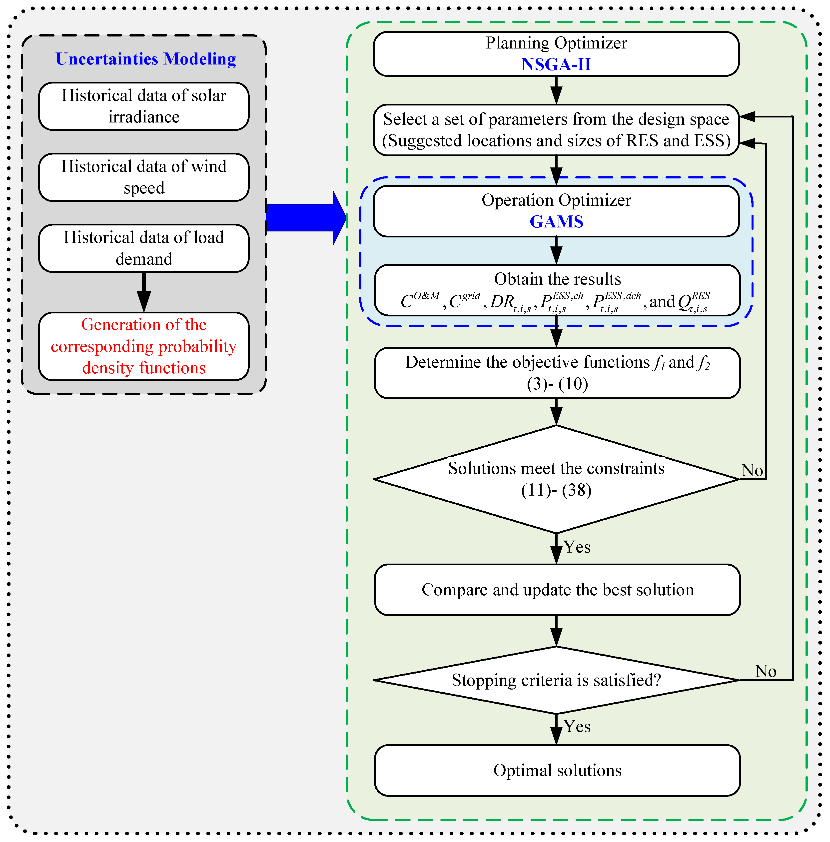
The locations and sizes of the RES and HESS are affected by their daily operation. Due to the complexity of the problem, it is not easy to solve it in one layer. Therefore, a nested, bi-level optimization framework is formulated to determine the optimal locations and capacities of the RES and HESS, as illustrated in Figure 2. The bi-level optimization framework is usually referred to as master-slave optimization, as it scales well with the size of the problem. In Figure 2, the uncertainties of the solar irradiance, wind speed, and load demand are modeled based on the Equations (39)–(43). The NSGA-II optimizer is employed for the planning level, while the GAMS optimizer is nested within the NSGA-II for optimal distribution system operation. This implies that every evaluation of the planning level requires the optimization of the operation level. At first, the limits of optimization variables are defined as the design space. These optimization variables of the planning level include the optimal locations and capacities of the PV systems, WT units, BES, SCES, and CAES. Then, NSGA-II is employed to find the optimal solution within the design space. The key steps of the bi-level optimization can be given as follows:
  • Take the suggested locations and sizes as the input of the inner optimizer from the design space of the NSGA-II;
  • GAMS optimizer is employed to evaluate the optimal charging/discharging power of the ESS, optimal reactive power of the RES interfacing inverters, and the DR factor to minimize the cost of the imported energy from the upstream grid and O&M costs of RES and ESS;
  • The obtained results by GAMS are used to determine the objective functions ( f 1 and f 2 ) based on the Equations (3)–(10);
  • Check if the current solutions meet the constraints (11)–(38) or not. If so, the best solutions are compared and updated. Otherwise, repeat the processes (1) to (3);
  • Repeat steps (1)–(4) until the stopping criteria are satisfied. Then, store the optimal obtained solutions.
It is important mentioning that the proposed approach can be applied for optimal operational planning of other energy storage devices such as hydrogen energy storage, hydro energy, etc.

5. Results and Discussion

5.1. Test System

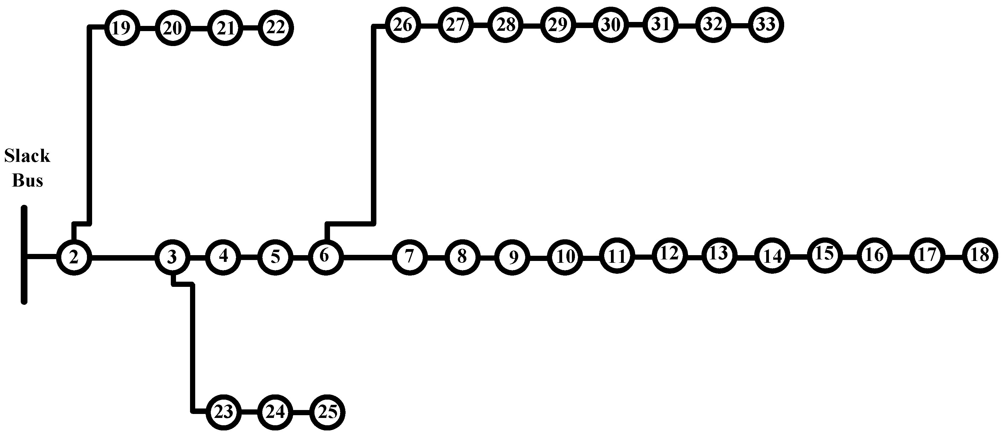
In this paper, the IEEE-33 bus test distribution system [47] is utilized to demonstrate the effectiveness of the proposed approach. The rated active power and reactive power of this system are, respectively, 3.72 MW and 2.3 MVar. On the other hand, it compromises one source with 12.66 kV, 33 buses, 32 branches, and three laterals, as shown in Figure 3. The active and reactive power losses for this radial distribution system in the base case are 210.998 kW and 143 kVar, respectively. Multiple RES and HESS should be optimally allocated in the distribution system while minimizing two conflicting objectives, including the total annual cost and VD. It is worth mentioning that the proposed approach is general. So, it can be applied to other higher complexity standard distribution systems.
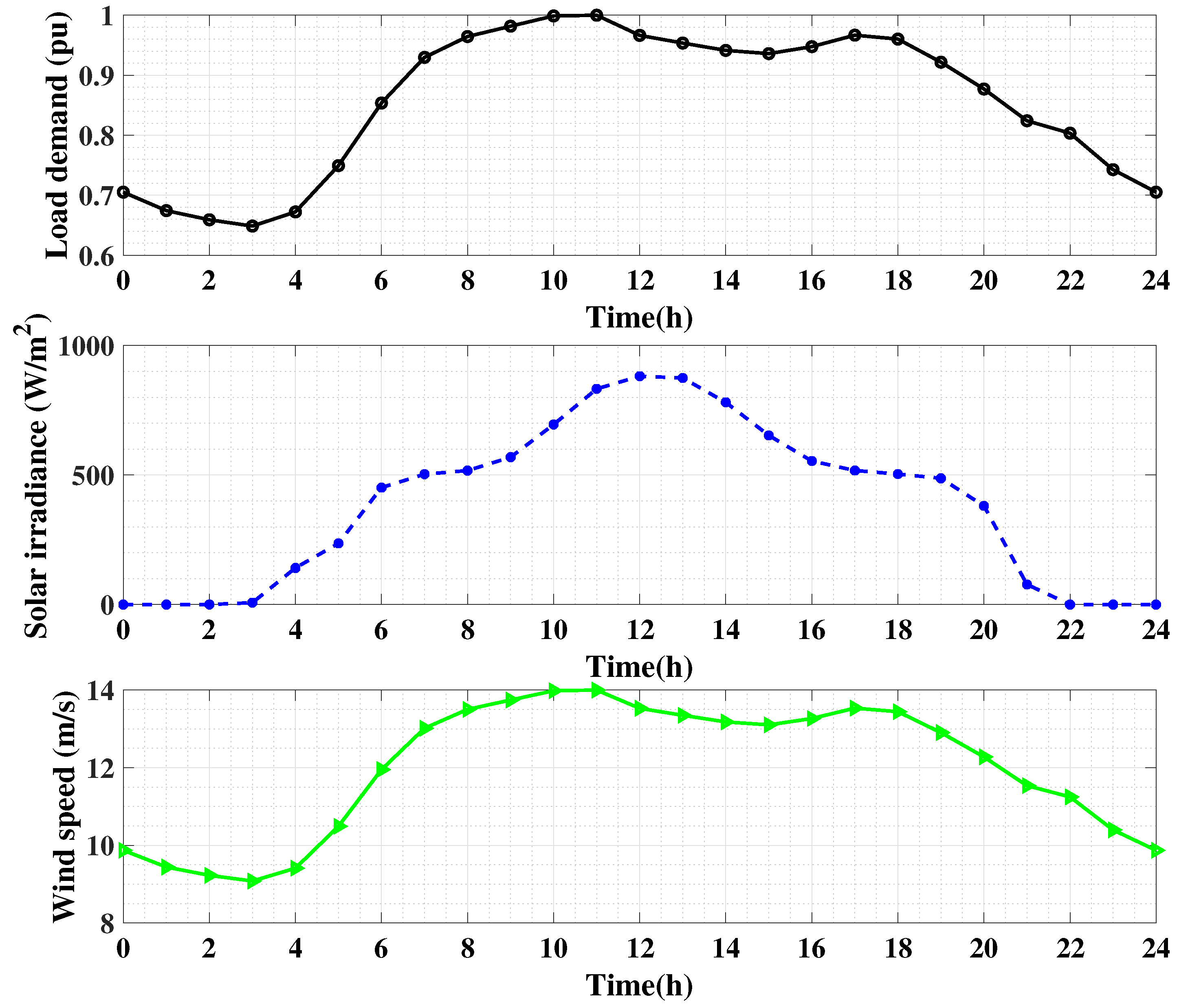
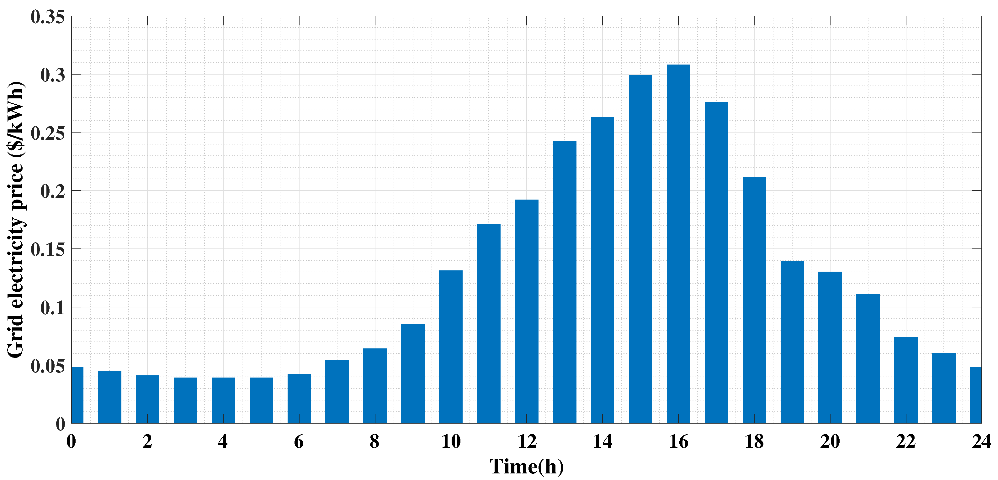
To demonstrate the effectiveness of the proposed operational planning approach, study cases are conducted based on historical wind speed data, historical solar irradiance data, and historical load demand data. Three years of recorded data sets are employed to determine the pdfs of the wind speed, solar irradiance, and load demand. Here, a day throughout the three years is used to represent them. This day is divided into 24-time segments, each time segment representing one hour. Hence, each time segment has a 1095 solar irradiance level, wind speed, or load demand ( 3 × 365 ). By utilizing these data, the mean and standard deviation for each time segment can be determined. Hence, the pdfs at each time segment can be generated. The historical data sets of the solar irradiance and wind speed are obtained from [48,49], while the historical load demand data are taken from [50]. The mean and standard deviation (SD) of the solar irradiance, wind speed, and load demand each time segment are given in Table 1. The expected hourly load profile, hourly solar irradiance, and hourly wind speed are shown in Figure 4. The main parameters used in this paper for WT, PV, Li-ion battery, SC, and CAES are shown in Table 2 and Table 3. The upper and lower limits of the control variables are taken from [2,51,52,53,54]. On the other hand, the hourly prices of the grid electrical energy are depicted in Figure 5. However, any other electricity pricing scheme can be used. The simulation results have been carried out in a MATLAB environment.

5.2. Case Studies

To study and evaluate the efficacy of the proposed operational planning approach to determine the optimal allocation of PV systems, WT units, and HESS (i.e., Li-ion battery, SC, and CAES), three different case studies have been conducted and compared considering the DR program and DSTATCOM functionality of the RES interfacing inverters. The three study cases can be described as follows:
  • Case 1: In this case, the RES are optimally allocated along with HESS without considering neither the DR program nor DSTATCOM functionality of the RES inverters;
  • Case 2: This case optimally allocates the RES and HESS considering the DR program only;
  • Case 3: This case is the proposed approach in which the RES and HESS (as in Case 2) are optimally allocated considering both the DR program and DSTATCOM functionality of the RES interfacing inverters.
In Case 1, the RES (i.e., WT units and PV systems) and HESS (i.e., Li-ion battery, SC, and CAES) are optimally allocated in the distribution system while the DR program and reactive power functionality of the inverters are disabled. On the other hand, only the DR program is enabled in Case 2, while both the DR program and reactive power functionality of the RES inverters are enabled in Case 3 in the planning approach.

5.3. Performance of the Suggested Approach

Here, the efficiency of the proposed approach for allocating hybrid RES and HESS is evaluated by employing the aforementioned three case studies is evaluated. Figure 6 shows the set of non-dominated solution points (Annual cost and VD) and the best-compromised solutions within these solutions based on the fuzzy logic theory for the different three case studies. The optimal capacities and locations of the RES and HESS obtained by the different case studies corresponding to these best-compromised solutions are given in Table 4. Figure 6 and Table 4 show that the annual cost and total VD are significantly decreased by employing the DR program and reactive power functionality of the RES interfacing inverters (i.e., Case 2 and Case 3) compared to Case 1. For instance, the annual cost and total VD are decreased by 9.78% and 4.8%, respectively, by applying Case 2, while they are decreased by 30.4% and 19%, respectively, by applying Case 3. On the other hand, the locations and capacities of the RES and energy storage systems vary based on the applied case study. Furthermore, Table 4 shows that the SC has a small rated capacity and larger rated power where the power cost of SC is low, and the capacity cost is high. The Li-ion battery has a medium-rated capacity and medium-rated power, while the CAES has a high-rated capacity and low-rated power. For instance, in Case 3, the rated capacities are 112 kWh, 14 kWh, and 143 kWh for the li-ion battery, SC, and CAES, respectively, while the rated powers are 22.4 kW, 2000 kW, and 14.3 kW, respectively.
Figure 7 illustrates the different case studies’ voltage profiles at different buses. This figure demonstrates that by applying the different case studies (Case 1–Case 3), the voltage profiles at all buses are kept within the thresholds of different case studies. One can observe that the voltage profiles in Case 2 are more leveled than those in Case 1 throughout the day. This levelization is due to employing the DR program in Case 2, which reduces the load demand in the peak period (peak shaving) and increases it in the off-peak period (valley filling), which, in turn, tries to level the load demand throughout the day. Furthermore, enabling the reactive power functionality of the interfacing inverters of RES in Case 3 provides further improvement and levelization in the voltage profiles. It makes all the voltages near unity at all buses due to the flexibility of reactive power injected/absorbed to/from the distribution system. This, in turn, leads to a significant decrease in the energy losses in the distribution system.
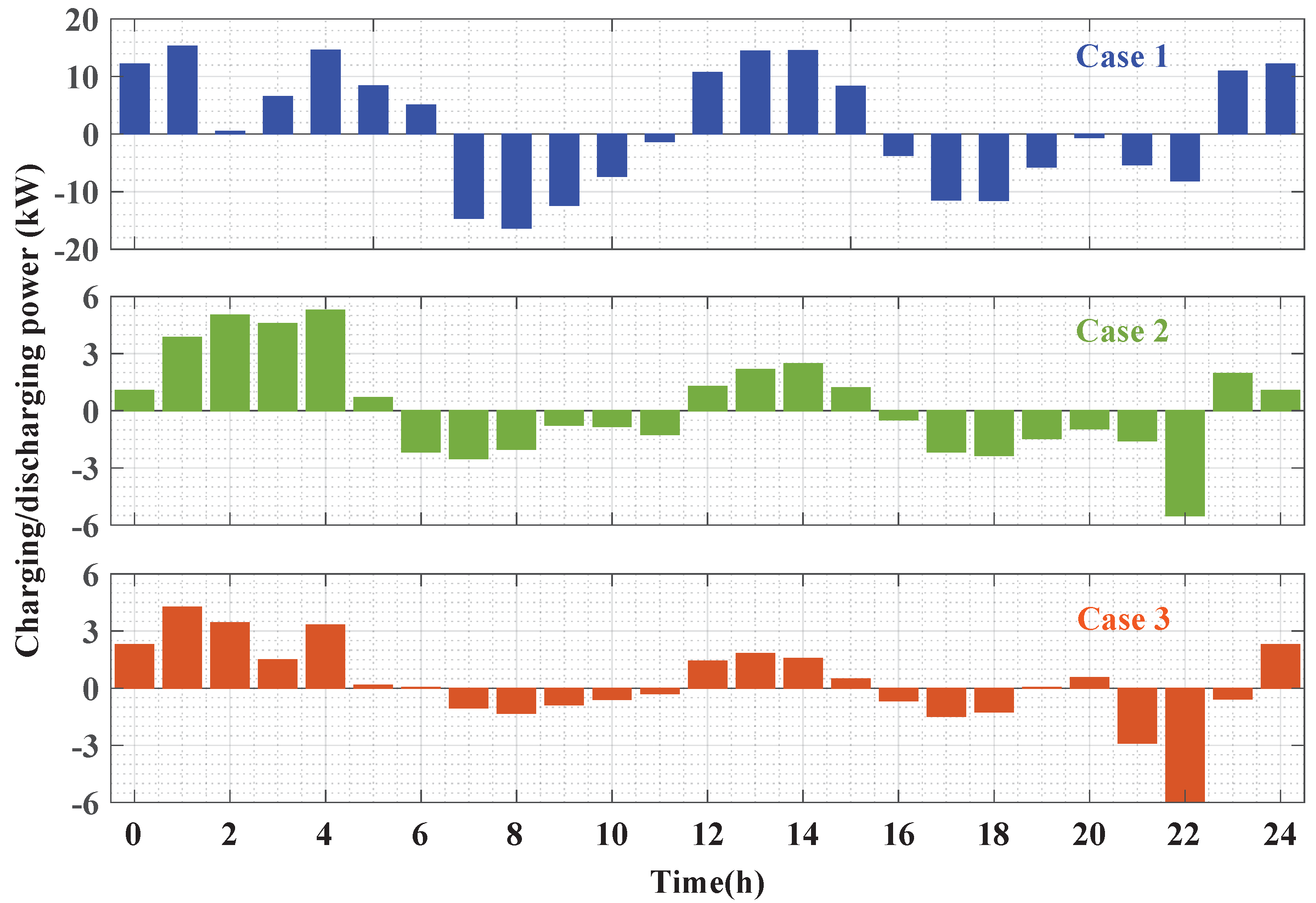
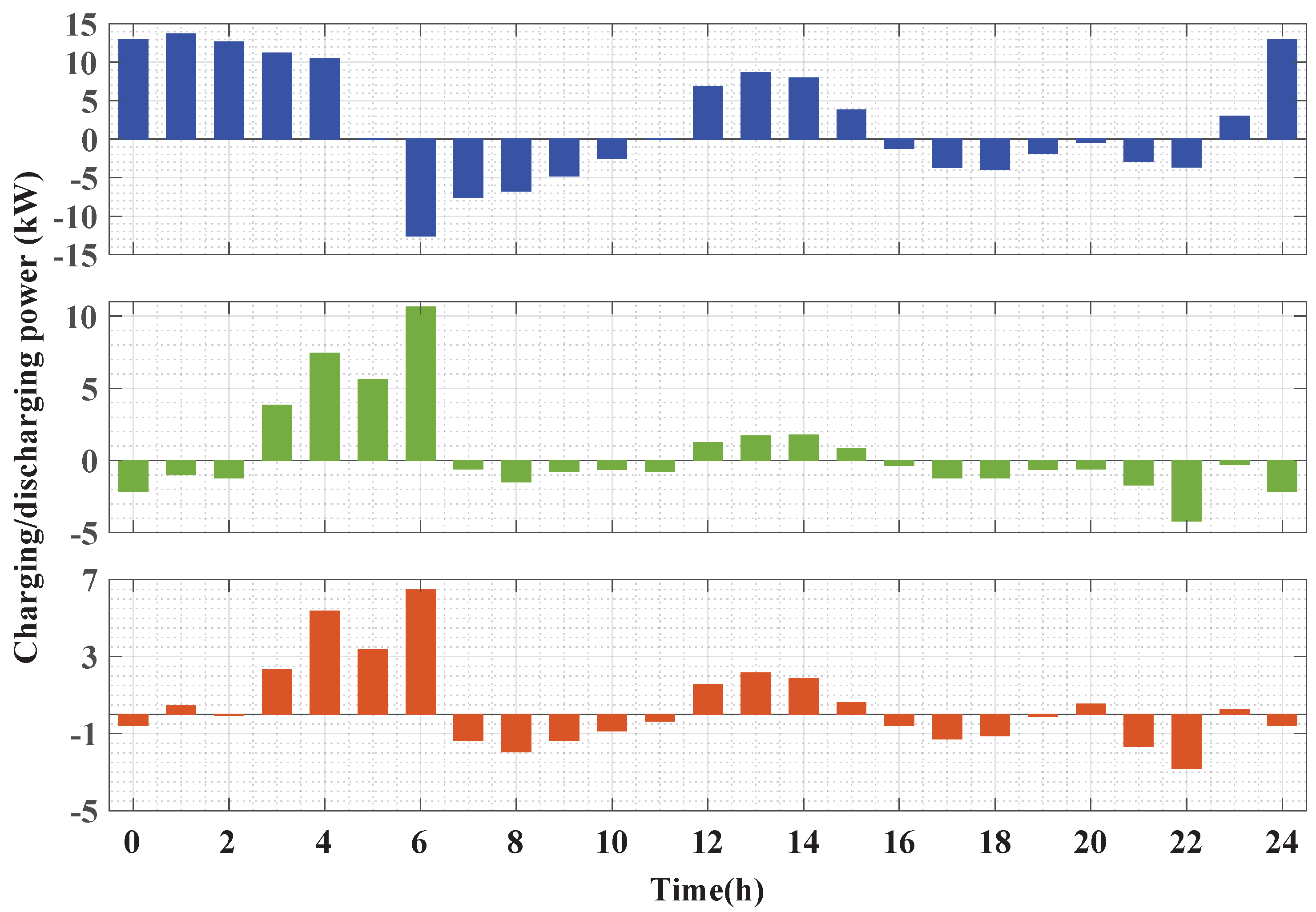
The charging and discharging powers of the different energy storage systems are depicted in Figure 8, Figure 9 and Figure 10. On the other hand, the corresponding SoC of these energy storage systems is given in Figure 11. These figures show that the energy storage systems tend to charge (positive values) during low electricity price periods or at high RES generation periods, while they tend to discharge (negative values) during periods of high electricity prices or low RES generation. This implies that the optimal allocation of HESS reduces the annual costs and increases the annual profits from selling the energy to the grid during the high prices periods. One can observe that the SoC of the BES, SCES, and CAES increase during charging and decrease during discharging, while they are kept at 50% of the rated capacity at the end of the day as constrained in (33). It is worth mentioning that employing the DR program (Case 2) decreases the stress on the ESS in terms of charging/discharging cycles and the amount of charging/discharging power which increases the lifetime of the ESS. A further decrease in charging/discharging cycles is observed in Case 3, in which the DR program and reactive power functionality of the RES interfacing inverters are enabled simultaneously. This indicates that the employing of the DR program and reactive power capability of the inverters not only decreases the annual cost and increases the profits, but also could increase the lifetime of the ESS.
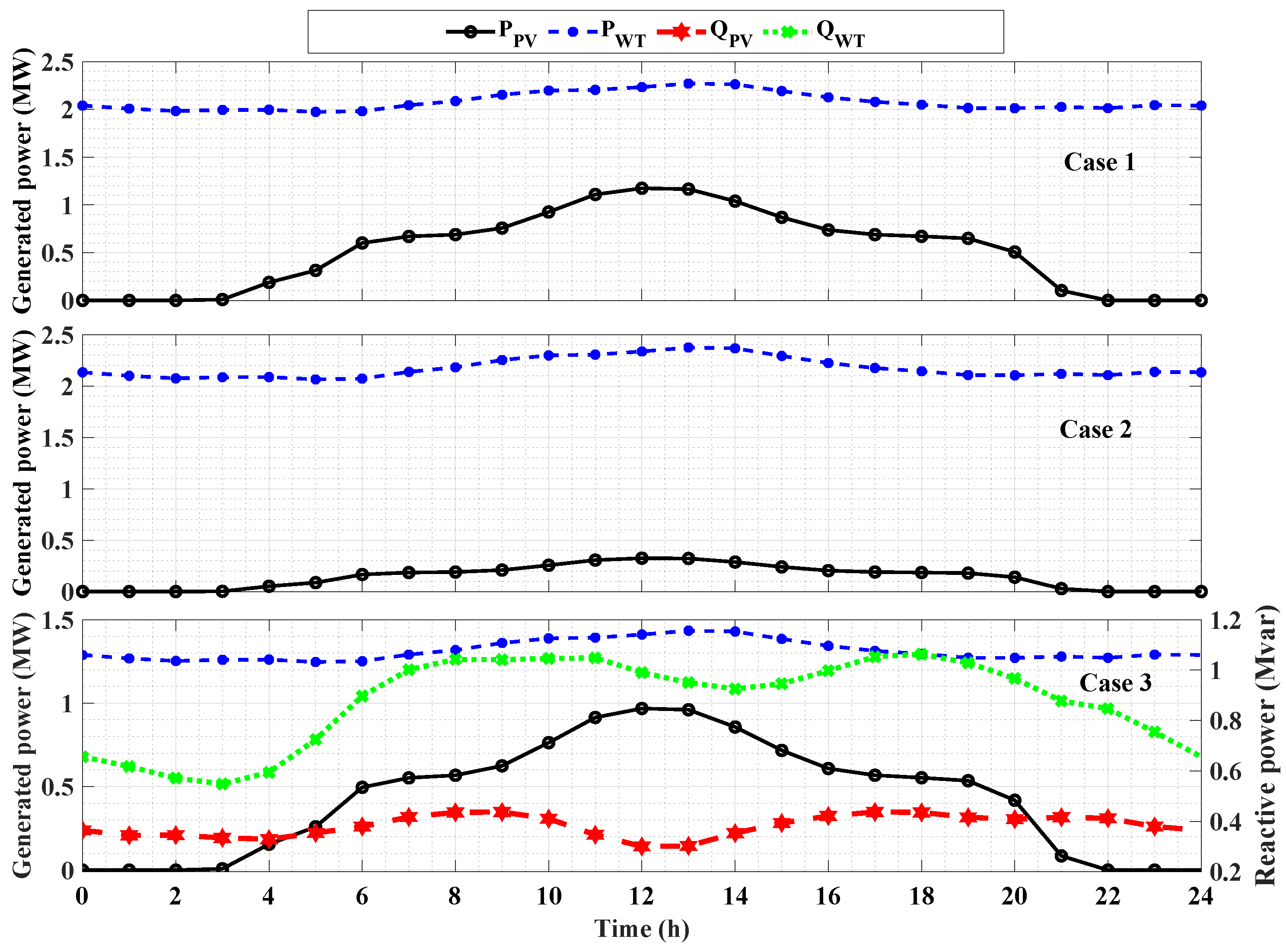
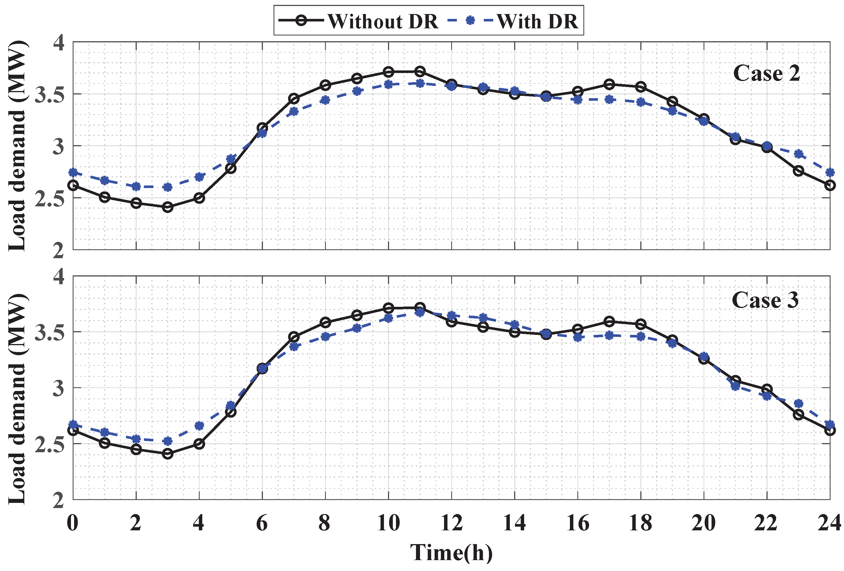
The hourly optimal active and reactive powers generated by PV systems and WT units are illustrated in Figure 12. These optimized reactive powers of the RES interfacing inverters greatly contribute to minimizing the annual cost and voltage profile improvements. The DR program is executed to shift the load demand from peak periods to off-peak periods, which reduces the system’s total operating cost. The hourly load demands with and without DR for Case 2 and Case 3 are shown in Figure 13. It is obvious that load demand has been shifted from the peak hours 7:00–12:00 and 16:00–19:00 to off-peak hours 0:00–5:00. The minimum amount of the load demand without applying the DR program is 2.4 MW at hour 3:00, while it is increased to 2.6 MW for Case 2 and 2.52 MW for Case 3 by applying the DR program. On the other hand, the maximum load demand without a DR program is 3.715 MW at hour 11:00, while it is decreased to 3.6 MW and 3.67 MW by applying the DR program for Case 2 and Case 3, respectively. The aforementioned results indicate that considering the DR program and reactive power functionality of the RES inverters in the planning problem of the RES and HESS have significant impacts on reducing the annual cost and improving the voltage profiles of the distribution systems.

6. Conclusions

In this paper, an operational planning approach has been proposed to determine the optimal sites and capacities of RES (PV and WT) and HESS (Li-ion battery, SC, and CAES) in distribution systems. The proposed approach’s advantages include: (1) the uncertainties of solar irradiance, wind speed, and load demand, (2) the price-based DR program, and (3) the DSTATCOM functionality of the RES interfacing inverters. The proposed approach has been formulated as a nested optimization problem to guarantee the optimal planning and operation of the RES and HESS simultaneously. Metaheuristic (NSGA-II) and mathematical (GAMS) algorithms have been employed to formulate the nested optimization solver for the operational planning problem. In particular, the NSGA-II optimizer has been utilized for the planning level. In contrast, the GAMS optimizer is nested within the NSGA-II for optimal operation of distribution systems. The total annual cost and total VD have been considered objective functions to be minimized. The proposed approach has been tested on the IEEE 33-bus distribution system. The effectiveness of the proposed approach has been demonstrated using a set of comprehensive case studies. The results demonstrate that the proposed approach optimally allocates the RES and HESS, simultaneously, with 30.4% cost reduction and 19% voltage deviation reduction compared to the base case without considering neither the DR program, nor the DSTATCOM functionality of RES. In the future, several aspects can be considered such as electric vehicles when acting as virtual power plants, how to meet the demand response, and what all strategies could be implemented.

Author Contributions

Conceptualization, A.A. and M.F.S.; Data curation, A.A. and H.F.S.; Formal analysis, A.A.; Investigation, A.A.; Methodology, A.A.; Project administration, M.F.S. and H.F.S.; Resources, A.A. and M.F.S.; Software, A.A.; Supervision, M.F.S. and H.F.S.; Validation, A.A.; Visualization, H.F.S.; Writing—original draft, A.A.; Writing—review & editing, A.A., M.F.S. and H.F.S. All authors have read and agreed to the published version of the manuscript.

Funding

This project was funded by the Deanship of Scientific Research (DSR), King Abdulaziz University, Jeddah, under grant No. (J: 54-135-1441). The authors, therefore, gratefully acknowledge DSR technical and financial support.

Institutional Review Board Statement

Not applicable.

Informed Consent Statement

Not applicable.

Data Availability Statement

Not applicable.

Conflicts of Interest

The authors declare no conflict of interest.

Abbreviations

BESBattery energy storage
BESSBattery energy storage system
CAESCompressed air energy storage
DoDDepth of discharge
DRDemand response
DSTATCOMDistribution static compensator
ESSEnergy storage systems
HESSHybrid energy storage systems
Li-ionlithium-ion batteries
GAMSGeneral algebraic modeling system
NSGA-IINon-dominated sorting genetic algorithm-II
O&MOperation and maintenance cost
pdfProbability distribution function
PVPhotovoltaics
RESRenewable energy sources
SCSupercapacitors
SCESsupercapacitor energy storage
SoCState of charge
VDTotal voltagemagnitude deviation
WTWind turbine

References

  1. Li, J.; Hu, D.; Mu, G.; Wang, S.; Zhang, Z.; Zhang, X.; Lv, X.; Li, D.; Wang, J. Optimal control strategy for large-scale VRB energy storage auxiliary power system in peak shaving. Int. J. Electr. Power Energy Syst. 2020, 120, 106007. [Google Scholar] [CrossRef]
  2. Feng, L.; Zhang, X.; Li, X.; Li, B.; Li, Y.; Xu, Y.; Guo, H.; Zhou, X.; Chen, H. Performance analysis of hybrid energy storage integrated with distributed renewable energy. Energy Rep. 2022, 8, 1829–1838. [Google Scholar] [CrossRef]
  3. Zhong, S.; Qiu, J.; Sun, L.; Liu, Y.; Zhang, C.; Wang, G. Coordinated planning of distributed WT, shared BESS and individual VESS using a two-stage approach. Int. J. Electr. Power Energy Syst. 2020, 114, 105380. [Google Scholar] [CrossRef]
  4. Alobaidi, A.H.; Khodayar, M.; Vafamehr, A.; Gangammanavar, H.; Khodayar, M.E. Stochastic expansion planning of battery energy storage for the interconnected distribution and data networks. Int. J. Electr. Power Energy Syst. 2021, 133, 107231. [Google Scholar] [CrossRef]
  5. Yan, N.; Zhang, B.; Li, W.; Ma, S. Hybrid energy storage capacity allocation method for active distribution network considering demand side response. IEEE Trans. Appl. Supercond. 2018, 29, 1–4. [Google Scholar] [CrossRef]
  6. Campos, R.A.; do Nascimento, L.R.; Rüther, R. The complementary nature between wind and photovoltaic generation in Brazil and the role of energy storage in utility-scale hybrid power plants. Energy Convers. Manag. 2020, 221, 113160. [Google Scholar] [CrossRef]
  7. Sepulveda, N.A.; Jenkins, J.D.; Edington, A.; Mallapragada, D.S.; Lester, R.K. The design space for long-duration energy storage in decarbonized power systems. Nat. Energy 2021, 6, 506–516. [Google Scholar] [CrossRef]
  8. Arbabzadeh, M.; Sioshansi, R.; Johnson, J.X.; Keoleian, G.A. The role of energy storage in deep decarbonization of electricity production. Nat. Commun. 2019, 10, 1–11. [Google Scholar] [CrossRef] [Green Version]
  9. Yacar, D.; Tejada-Arango, D.A.; Wogrin, S. Storage allocation and investment optimisation for transmission-constrained networks considering losses and high renewable penetration. IET Renew. Power Gener. 2018, 12, 1949–1956. [Google Scholar] [CrossRef]
  10. Tan, K.M.; Babu, T.S.; Ramachandaramurthy, V.K.; Kasinathan, P.; Solanki, S.G.; Raveendran, S.K. Empowering smart grid: A comprehensive review of energy storage technology and application with renewable energy integration. J. Energy Storage 2021, 39, 102591. [Google Scholar] [CrossRef]
  11. Wen, S.; Lan, H.; Fu, Q.; David, C.Y.; Zhang, L. Economic allocation for energy storage system considering wind power distribution. IEEE Trans. Power Syst. 2014, 30, 644–652. [Google Scholar] [CrossRef]
  12. Wang, X.; Li, Z.; Shahidehpour, M.; Jiang, C. Robust line hardening strategies for improving the resilience of distribution systems with variable renewable resources. IEEE Trans. Sustain. Energy 2017, 10, 386–395. [Google Scholar] [CrossRef]
  13. Ali, A.; Mahmoud, K.; Lehtonen, M. Optimization of photovoltaic and wind generation systems for autonomous microgrids with PEV-parking lots. IEEE Syst. J. 2021, 16, 3260–3271. [Google Scholar] [CrossRef]
  14. Lara, J.D.; Olivares, D.E.; Canizares, C.A. Robust energy management of isolated microgrids. IEEE Syst. J. 2018, 13, 680–691. [Google Scholar] [CrossRef]
  15. Du, Y.; Wu, J.; Li, S.; Long, C.; Onori, S. Coordinated energy dispatch of autonomous microgrids with distributed MPC optimization. IEEE Trans. Ind. Inform. 2019, 15, 5289–5298. [Google Scholar] [CrossRef]
  16. Xu, D.; Zhou, B.; Wu, Q.; Chung, C.Y.; Li, C.; Huang, S.; Chen, S. Integrated modelling and enhanced utilization of power-to-ammonia for high renewable penetrated multi-energy systems. IEEE Trans. Power Syst. 2020, 35, 4769–4780. [Google Scholar] [CrossRef]
  17. Ali, A.; Mahmoud, K.; Lehtonen, M. Multiobjective photovoltaic sizing with diverse inverter control schemes in distribution systems hosting EVs. IEEE Trans. Ind. Inform. 2020, 17, 5982–5992. [Google Scholar] [CrossRef]
  18. Atwa, Y.M.; El-Saadany, E.F.; Salama, M.M.A.; Seethapathy, R. Optimal Renewable Resources Mix for Distribution System Energy Loss Minimization. IEEE Trans. Power Syst. 2010, 25, 360–370. [Google Scholar] [CrossRef]
  19. Alismail, F.; Xiong, P.; Singh, C. Optimal wind farm allocation in multi-area power systems using distributionally robust optimization approach. IEEE Trans. Power Syst. 2017, 33, 536–544. [Google Scholar] [CrossRef]
  20. Kumar, M.; Tyagi, B. An optimal multivariable constrained nonlinear (MVCNL) stochastic microgrid planning and operation problem with renewable penetration. IEEE Syst. J. 2020, 14, 4143–4154. [Google Scholar] [CrossRef]
  21. Akram, U.; Khalid, M.; Shafiq, S. Optimal sizing of a wind/solar/battery hybrid grid-connected microgrid system. IET Renew. Power Gener. 2018, 12, 72–80. [Google Scholar] [CrossRef]
  22. Vahidinasab, V. Optimal distributed energy resources planning in a competitive electricity market: Multiobjective optimization and probabilistic design. Renew. Energy 2014, 66, 354–363. [Google Scholar] [CrossRef]
  23. Somakumar, R.; Kasinathan, P.; Monicka, G.; Rajagopalan, A.; Ramachandaramurthy, V.K.; Subramaniam, U. Optimization of emission cost and economic analysis for microgrid by considering a metaheuristic algorithm-assisted dispatch model. Int. J. Numer. Model. Electron. Netw. Devices Fields 2022, 35, 1–25. [Google Scholar] [CrossRef]
  24. Ali, A.; Mahmoud, K.; Lehtonen, M. Maximizing hosting capacity of uncertain photovoltaics by coordinated management of OLTC, VAr sources and stochastic EVs. Int. J. Electr. Power Energy Syst. 2021, 127, 106627. [Google Scholar] [CrossRef]
  25. Aleem, S.A.; Hussain, S.S.; Ustun, T.S. A review of strategies to increase PV penetration level in smart grids. Energies 2020, 13, 636. [Google Scholar] [CrossRef] [Green Version]
  26. Ali, A.; Mahmoud, K.; Lehtonen, M. Enhancing hosting capacity of intermittent wind turbine systems using bi-level optimisation considering OLTC and electric vehicle charging stations. IET Renew. Power Gener. 2020, 14, 3558–3567. [Google Scholar] [CrossRef]
  27. Nguyen-Hong, N.; Nguyen-Duc, H.; Nakanishi, Y. Optimal sizing of energy storage devices in isolated wind-diesel systems considering load growth uncertainty. IEEE Trans. Ind. Appl. 2018, 54, 1983–1991. [Google Scholar] [CrossRef]
  28. Hajipour, E.; Bozorg, M.; Fotuhi-Firuzabad, M. Stochastic capacity expansion planning of remote microgrids with wind farms and energy storage. IEEE Trans. Sustain. Energy 2015, 6, 491–498. [Google Scholar] [CrossRef]
  29. Zheng, Y.; Hill, D.J.; Dong, Z.Y. Multi-agent optimal allocation of energy storage systems in distribution systems. IEEE Trans. Sustain. Energy 2017, 8, 1715–1725. [Google Scholar] [CrossRef]
  30. Soltani, N.Y.; Nasiri, A. Chance-constrained optimization of energy storage capacity for microgrids. IEEE Trans. Smart Grid 2020, 11, 2760–2770. [Google Scholar] [CrossRef]
  31. Zhao, B.; Ren, J.; Chen, J.; Lin, D.; Qin, R. Tri-level robust planning-operation co-optimization of distributed energy storage in distribution networks with high PV penetration. Appl. Energy 2020, 279, 115768. [Google Scholar] [CrossRef]
  32. Barani, M.; Aghaei, J.; Akbari, M.A.; Niknam, T.; Farahmand, H.; Korpås, M. Optimal partitioning of smart distribution systems into supply-sufficient microgrids. IEEE Trans. Smart Grid 2018, 10, 2523–2533. [Google Scholar] [CrossRef]
  33. Monteiro, M.R.; Alvarenga, G.F.; Rodrigues, Y.R.; de Souza, A.Z.; Lopes, B.; Passaro, M.C.; Abdelaziz, M. Network partitioning in coherent areas of static voltage stability applied to security region enhancement. Int. J. Electr. Power Energy Syst. 2020, 117, 105623. [Google Scholar] [CrossRef]
  34. Hosseinnezhad, V.; Rafiee, M.; Ahmadian, M.; Siano, P. A comprehensive framework for optimal day-ahead operational planning of self-healing smart distribution systems. Int. J. Electr. Power Energy Syst. 2018, 99, 28–44. [Google Scholar] [CrossRef]
  35. Oskouei, M.Z.; Mohammadi-Ivatloo, B.; Erdinc, O.; Erdinç, F.G. Optimal allocation of renewable sources and energy storage systems in partitioned power networks to create supply-sufficient areas. IEEE Trans. Sustain. Energy 2020, 12, 999–1008. [Google Scholar] [CrossRef]
  36. Fani, B.; Shahgholian, G.; Alhelou, H.H.; Siano, P. Inverter-Based Islanded Microgrid: A Review on Technologies and Control. e-Prime-Adv. Electr. Eng. Electron. Energy 2022, 2, 100068. [Google Scholar]
  37. Albadi, M.H.; El-Saadany, E.F. A summary of demand response in electricity markets. Electr. Power Syst. Res. 2008, 78, 1989–1996. [Google Scholar] [CrossRef]
  38. Ferreira, R.d.S.; Barroso, L.; Carvalho, M.M. Demand response models with correlated price data: A robust optimization approach. Appl. Energy 2012, 96, 133–149. [Google Scholar] [CrossRef]
  39. Lee, M.; Aslam, O.; Foster, B.; Kathan, D.; Kwok, J.; Medearis, L.; Palmer, R.; Sporborg, P.; Tita, M. Assessment of Demand Response and Advanced Metering; Tech. Rep.; Federal Energy Regulatory Commission: Washington, DC, USA, 2013.
  40. Aalami, H.; Moghaddam, M.P.; Yousefi, G. Modeling and prioritizing demand response programs in power markets. Electr. Power Syst. Res. 2010, 80, 426–435. [Google Scholar] [CrossRef]
  41. Deb, K.; Pratap, A.; Agarwal, S.; Meyarivan, T. A fast and elitist multiobjective genetic algorithm: NSGA-II. IEEE Trans. Evol. Comput. 2002, 6, 182–197. [Google Scholar] [CrossRef] [Green Version]
  42. General Algebraic Modeling System (GAMS). 2022. Available online: https://www.gams.com/ (accessed on 13 July 2022).
  43. IEEE Std. 1547-2018 (Revis. IEEE Std 1547-2003); IEEE Standard for Interconnection and Interoperability of Distributed Energy Resources with Associated Electric Power Systems Interfaces. IEEE: Piscataway, NJ, USA, 2018.
  44. Gangwar, T.; Padhy, N.P.; Jena, P. Storage Allocation in Active Distribution Networks considering Life-cycle and Uncertainty. IEEE Trans. Ind. Inform. 2022, 1. [Google Scholar] [CrossRef]
  45. Ali, A.; Raisz, D.; Mahmoud, K. Optimal oversizing of utility-owned renewable DG inverter for voltage rise prevention in MV distribution systems. Int. J. Electr. Power Energy Syst. 2019, 105, 500–513. [Google Scholar] [CrossRef]
  46. Ali, A.; Mahmoud, K.; Raisz, D.; Lehtonen, M. Probabilistic approach for hosting high PV penetration in distribution systems via optimal oversized inverter with watt-var functions. IEEE Syst. J. 2020, 15, 684–693. [Google Scholar] [CrossRef]
  47. Baran, M.E.; Wu, F.F. Network reconfiguration in distribution systems for loss reduction and load balancing. IEEE Power Eng. Rev. 1989, 9, 101–102. [Google Scholar] [CrossRef]
  48. Andreas, A.; Stoffel, T. Nevada Power: Clark Station; Las Vegas, Nevada (Data). 2006. Available online: https://midcdmz.nrel.gov/npcs/ (accessed on 1 June 2022).
  49. Historical Climate Data—Climate—Environment and Climate Change Canada. 2019. Available online: http://climate.weather.gc.ca/ (accessed on 1 June 2022).
  50. European Network of Transmission System Operators for Electricity. 2019. Available online: https://www.entsoe.eu/ (accessed on 1 June 2022).
  51. Wind Turbine Models. Available online: https://en.wind-turbine-models.com/turbines/1682-hummer-h25.0-100kw (accessed on 20 June 2022).
  52. Biswas, P.P.; Suganthan, P.; Amaratunga, G.A. Optimal power flow solutions incorporating stochastic wind and solar power. Energy Convers. Manag. 2017, 148, 1194–1207. [Google Scholar] [CrossRef]
  53. Blumsack, S. Basic economics of power generation, transmission and distribution. Energy Mark. Policy Regul. Course Pennstate Coll. Dep. Energy Miner. Eng. 2018, 13. Available online: https://www.e-education.psu.edu/eme801/node/530 (accessed on 20 June 2020).
  54. Peng, C.; Xiong, Z.; Zhang, Y.; Zheng, C. Multi-objective robust optimization allocation for energy storage using a novel confidence gap decision method. Int. J. Electr. Power Energy Syst. 2022, 138, 107902. [Google Scholar] [CrossRef]
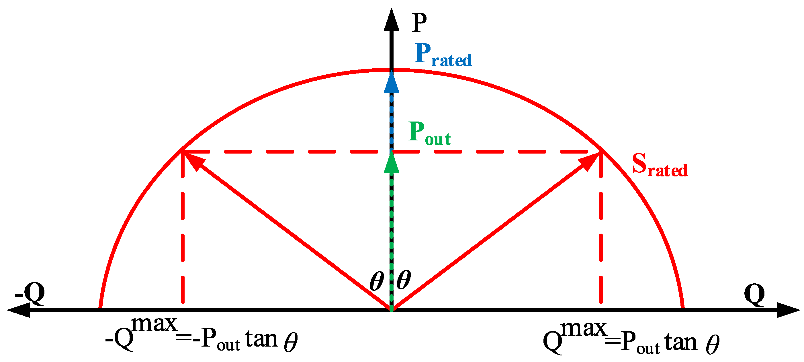
Figure 1. Reactive power capability curve of a voltage source inverter.
Sustainability 14 13209 g001
Figure 2. Structure of the nested optimization framework.
Sustainability 14 13209 g002
Figure 3. Single line diagram of the IEEE 33-bus distribution test system.
Sustainability 14 13209 g003
Figure 4. Hourly expected load profile, solar irradiance, and wind speed.
Sustainability 14 13209 g004
Figure 5. Hourly electricity price of the grid.
Sustainability 14 13209 g005
Figure 6. Pareto-optimal solutions were obtained for the different case studies.
Sustainability 14 13209 g006
Figure 7. Voltage profiles of different buses for different case studies (Each line (color) represents the voltage profile at a respected bus).
Sustainability 14 13209 g007
Figure 8. Charging and discharging powers of the Li-ion batteries for different case studies.
Sustainability 14 13209 g008
Figure 9. Charging and discharging powers of the SC for different case studies.
Sustainability 14 13209 g009
Figure 10. Charging and discharging powers of the CAES for different case studies.
Sustainability 14 13209 g010
Figure 11. SoC of the different ESS for different case studies.
Sustainability 14 13209 g011
Figure 12. Hourly active and reactive powers generated by PV systems and WT units.
Sustainability 14 13209 g012
Figure 13. The hourly load demands with and without DR for Case 2 and Case 3.
Sustainability 14 13209 g013
Table 1. Hourly mean and SD of the solar irradiance, wind speed, and load demand.
TimeSolar Irradiance (kW/m2)Wind Speed (m/s)Load Demand (%)
MeanSDMeanSDMeanSD
10.0000.0007.6804.77965.1774.698
20.0000.0007.4874.92762.0184.410
30.0000.0007.2674.88258.7585.230
40.0000.0007.3164.77957.7564.220
50.0000.0007.3554.84758.7764.614
60.0020.0127.2204.95562.2236.212
70.0250.0477.2634.91470.7839.278
80.1080.1057.7144.79076.0109.321
90.2550.1487.9814.65078.1158.115
100.4160.1718.4844.67179.9697.260
110.5650.1988.7544.59281.1746.852
120.6590.2108.8474.67281.9496.811
130.7130.2299.1594.81582.1037.116
140.7030.2379.3174.66181.0377.444
150.6370.2319.1134.41280.5397.616
160.5290.2288.7664.68280.6407.944
170.4160.2208.3954.87481.1148.291
180.2780.1918.0374.88281.0938.775
190.1490.1427.7504.77381.0508.558
200.0600.0827.5584.96781.5097.702
210.0140.0287.5124.89080.6616.040
220.0000.0017.6454.94377.8765.348
230.0000.0007.4834.80873.6895.373
240.0000.0007.7434.84869.9795.167
Table 2. The main parameters of RES [2,51,52,53].
Wind Turbine ParametersPV Parameters
Unit price ($/kW)1075Unit price ($/kW)615
Lifetime (years)20Lifetime (years)20
Rated power(kW)100 R s t d (W/m 2 )1000
Cut-in speed (m/s)2.5 R c (W/m 2 )120
Rated speed (m/s)10O&M cost ($/kWh)0.01
Cut-off speed (m/s)20
O&M cost ($/kWh)0.01
Table 3. The main parameters of the energy storage systems [2].
IndexLi-Ion BatterySupercapacitorCAES
Unit price of power770 ($/kW)70 ($/kW)920 ($/kW)
Unit price of capacity385 ($/kWh)1765 ($/kWh)230 ($/kWh)
Lifetime10 (years)10 (years)30 (years)
S o C m a x 100 (%)100 (%)100 (%)
S o C m i n 20 (%)5 (%)10 (%)
Charging efficiency90 (%)95 (%)75 (%)
Discharging efficiency90 (%)95 (%)75 (%)
Table 4. Obtained best-compromised solutions by applying different case studies.
IndexCase 1Case 2Case 3
PV locations7 & 218 & 218 & 21
PV capacities (MW)1.16 & 0.170.19 & 0.170.58 & 0.51
WT locations12 & 2915 & 3114 & 30
WT capacities(unit)22 & 1519 & 2112 & 12
Battery location161117
Battery capacity (kWh)134110112
Battery power (kW)26.802222.4
SC location222021
SC capacity (kWh)10.51014
SC power (kW)8803882000
CAES location272128
CAES capacity (kWh)180227143
CAES power (kW)1822.714.3
Annual cost (M$/yaer)0.6850.6180.477
Total VD (pu)6.466.155.24
Cost reduction (%)-9.7830.4
Reduction of VD (%)-4.8019
Publisher’s Note: MDPI stays neutral with regard to jurisdictional claims in published maps and institutional affiliations.