Article

Waste Heat Driven Integrated Membrane Distillation for Concentrating Nutrients and Process Water Recovery at a Thermophilic Biogas Plant

1
HVR Water Purification AB, Vasagatan 7, 111 20 Stockholm, Sweden
2
Department of Energy and Technology, SLU-Swedish University of Agricultural Sciences, 750 07 Uppsala, Sweden
3
Uppsala Vatten och Avfall AB, 751 44 Uppsala, Sweden
*
Author to whom correspondence should be addressed.
Sustainability 2022, 14(20), 13535; https://doi.org/10.3390/su142013535
Submission received: 2 September 2022 / Revised: 14 October 2022 / Accepted: 17 October 2022 / Published: 19 October 2022
(This article belongs to the Special Issue Wastewater Treatment and Sustainability of Development)

Abstract

:
To efficiently utilize low-concentrate digestate nutrients, further treatment is needed to decrease their volume, recover process water, and increase nutrient concentrations. Membrane distillation (MD) is a thermally driven process that is advantageous due to its ability to harness low-grade waste heat to treat highly complex wastewater streams. This study assessed the techno-economic performance of integrating MD for two-fold concentrations of nutrients and the recovery of process water from digestate at a thermophilic biogas plant. Thermal assessment showed that the recovered waste heat from flue gas and digestate fully met the thermal energy demand of MD and saved 20% of boiler energy by heating incoming slurry. The permeate flux from MD was 3.5 L/(m2h) and 3.1 L/(m2h) at 66 °C and 61 °C digestate inlet temperatures during winter and summer, respectively. With internal heat recovery, the specific heat demand for MD was 80 kWh/m3 and 100 kWh/m3 in winter and summer, respectively. The unit cost of MD permeate was estimated to be 3.6 €/m3 and 4.1 €/m3 at a digestate feed temperature of 66 °C and 61 °C (with heat recovery), and 7.6 €/m3 and 9.1 €/m3 (without heat recovery) in winter and summer, respectively. However, cost sensitivity analyses showed that waste heat recovery and thermal energy cost variations had a significant impact on the MD permeate production cost. Nevertheless, the economic assessment indicated that the thermal integration of a biogas plant with industrial-scale MD digestate treatment capacity could be economically feasible, with winter being more economically favorable due to higher waste heat recovery.

1. Introduction

Anaerobic co-digestion (AD) of organic waste is progressively being used to supply renewable energy, for the production of combined heat and power (CHP) or transport fuel, and effluent digestate as a liquid fertilizer for farming [1]. The digestate is rich in plant nutrients, but its fertilizer value is usually low due to its high water content (90–95%) [2], leading to high costs for transportation, storage, and spreading on farmland [3,4]. To overcome this problem, the digestate can be processed for volume reduction, i.e., concentrating the nutrients and obtaining a process water, which can be recycled and used for the dilution of the incoming solid substrate. Phase separation of the digestate with a decanter centrifuge or screw press is a commonly applied technologies [5]. However, the separation process does not always eliminate the desired amount of total solids (TS) from the digestate [5,6,7]. For more comprehensive processing, complicated methods and technologies are required, but those currently available have various degrees of technical development, high energy inputs, and high investment and operating costs [5]. Membrane technologies have been recommended for the recovery of nutrients from slurries [8,9]. However, the nano-filtration (NF), membrane filtration (MF), and reverse osmosis (RO) processes are prone to membrane fouling, and the formation of a polarization film in wastewater nutrient recovery, where the feed stream has high TS and nutrient content [2,10]. Moreover, other existing technologies run into limitations (such as high electricity demand, high pressure, and corrosion in evaporators).
Membrane distillation (MD) is a heat-driven membrane separation/purification technology whereby water vapor molecules are transported through a hydrophobic microporous membrane by temperature gradient-induced vapor pressure [2,11,12,13,14]. MD operates at below 90 °C on the hot feed side, which makes it appropriate for thermal integration with different heat sources [2,11,15,16]. Utilization of MD has been investigated for multiple applications, such as digestate reject water treatment in mesophilic conditions [2,17], food and beverage processing [18,19,20,21], concentration of sucrose solution [22], textile industry effluent recycling [23,24,25], and municipal wastewater treatment [26,27]. However, a commercial breakthrough for MD technology in wastewater treatment on an industrial scale has not been accomplished so far.
Thermophilic anaerobic digestion (AD) can increase the rate of biogas production by 41–144% compared with mesophilic digestion [28]. However, the heat demand accounts for 70–80% of the total energy consumption [29]. The heat losses from the substrate sanitization and digester units depend on the reactor design and on the difference between the reactor temperature and outside temperature [30,31]. Internal waste heat recovery can be a cost-effective solution for the utilization of waste heat and for improving the overall energy efficiency in existing industrial systems such as biogas plants. Previous studies have shown that considerable amounts of energy can be recovered when the feed is preheated by an effluent digestate [32,33]. However, a substantial amount of waste heat in exhausted flue gases from the sanitation steam boiler usually remains unused in the biogas plant due to the limited applicability [15,16]. Moreover, the quantitative contribution of waste heat recovery from digestate and flue gases to the net energy output is unclear [34]. Thus, further information is needed about the mass, nutrients, and overall energy balances of an AD plant with integrated digestate liquid treatment. The integrated approach brings advantages related to matching resource availability with demand for the concentrated nutrients, process water, and energy services, while integration between components ensures high conversion efficiencies and hence low costs [15]. A preceding study has established the benefits of integrated energy schemes for power and heat generation [15,16,32,34]. To the best of the authors’ knowledge, thermophilic AD with integrated MD treatment for digestate has not been assessed previously.
The overall objective of the study was to assess the techno-economic performance of digestate separation and concentration at a full-scale thermophilic biogas plant integrated with MD technology. For the proposed integrated AD–MD system, the mass, nutrients, and energy balances were calculated, and nutrient and process water recovery, mass reduction, waste heat recovery, and energy efficiencies were determined, based on typical thermophilic co-digestion Uppsala biogas plant values from full-scale studies. Economic assessment was performed for typical scenarios of a full-scale biogas plant at Uppsala Vatten och Avfall AB, Uppsala, Sweden, in order to assess the cost impacts of the thermal integration of AD with MD.

2. Materials and Methods

The current operating conditions in winter and summer at the Uppsala Vatten och Avfall AB biogas plant are described in Section 2.1. The characteristics of the digestate are presented in Section 2.2, and the method used to determine the energy consumption of the existing biogas plant is described in Section 2.3. The basic features of the plant and different unit operations in terms of mass and energy balance were evaluated to provide input data for calculations on the thermal integration of an industrial MD system (Section 2.4) into the AD biogas production system (Section 2.5). Assessment of heat integration was accompanied by applying the principle of energy and material balance for distinctive scenarios defined by the usual working conditions of both the AD and MD processes. The heat energy demand, separation efficiency, and permeate production rate (flux) of the MD unit were calculated based on the performance of a laboratory-scale unit in a previous study [2]. In order to assess whether waste heat recovery and the thermal integration of the AD–MD system is an economical alternative, a general cost analysis (including sensitivity analyses) was performed (Section 2.6).

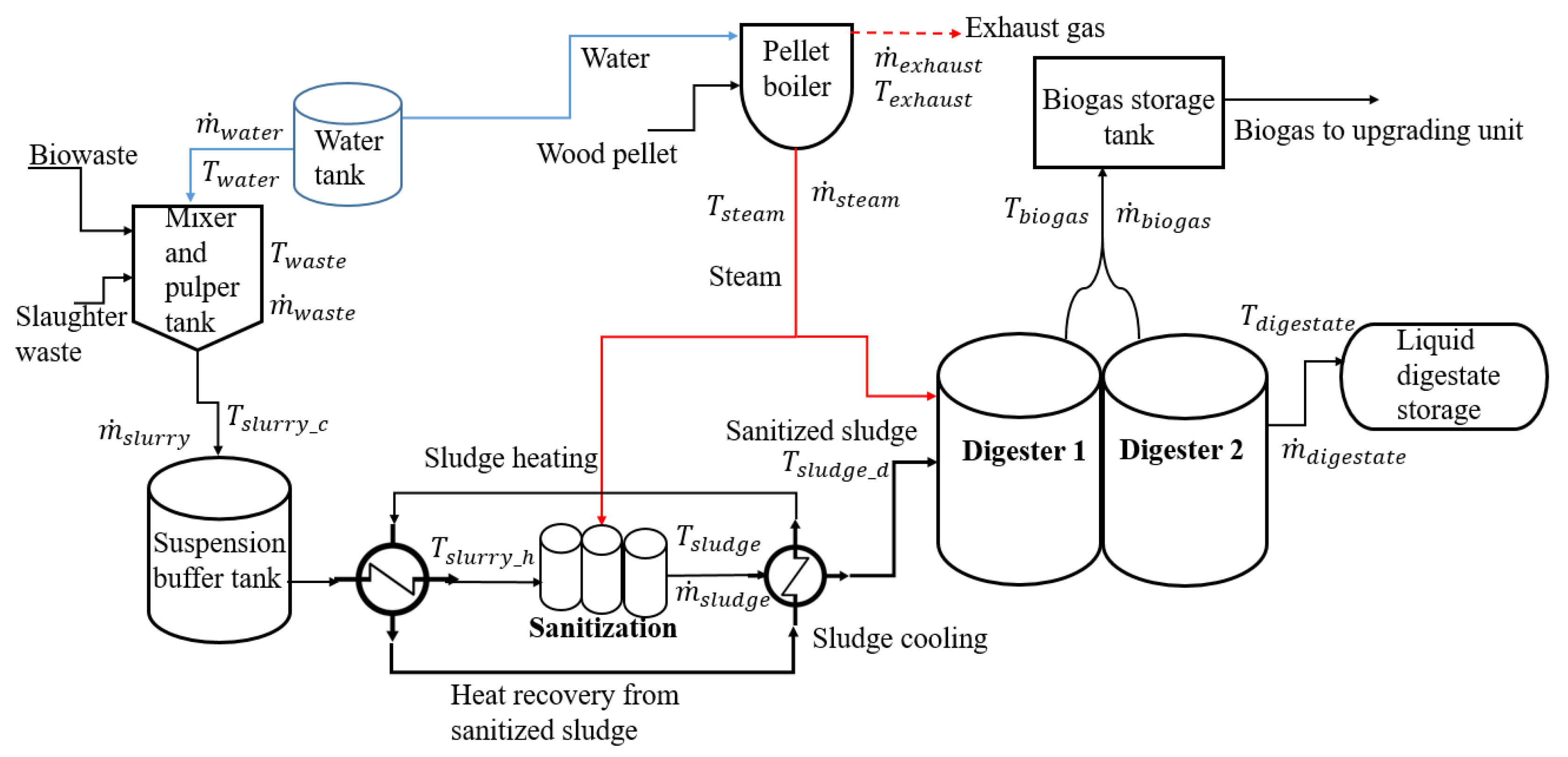
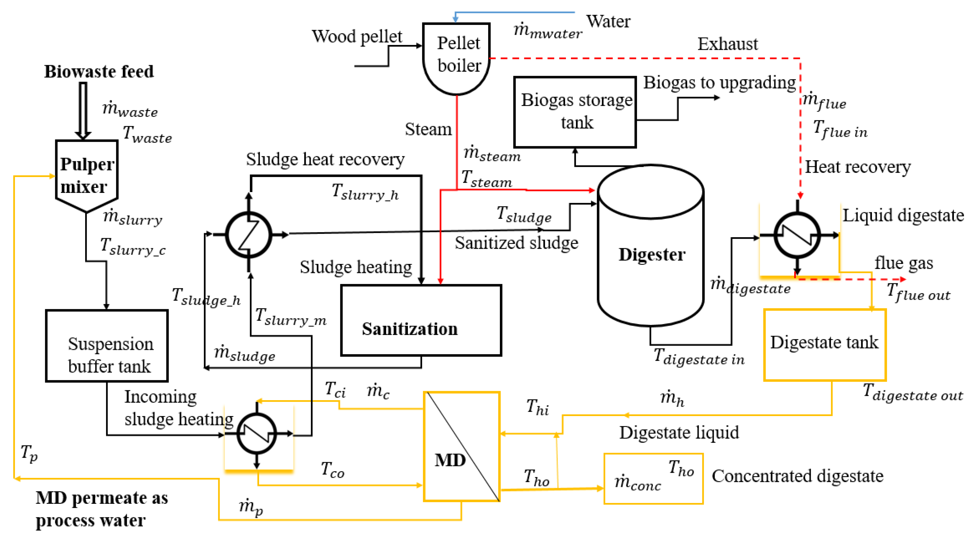
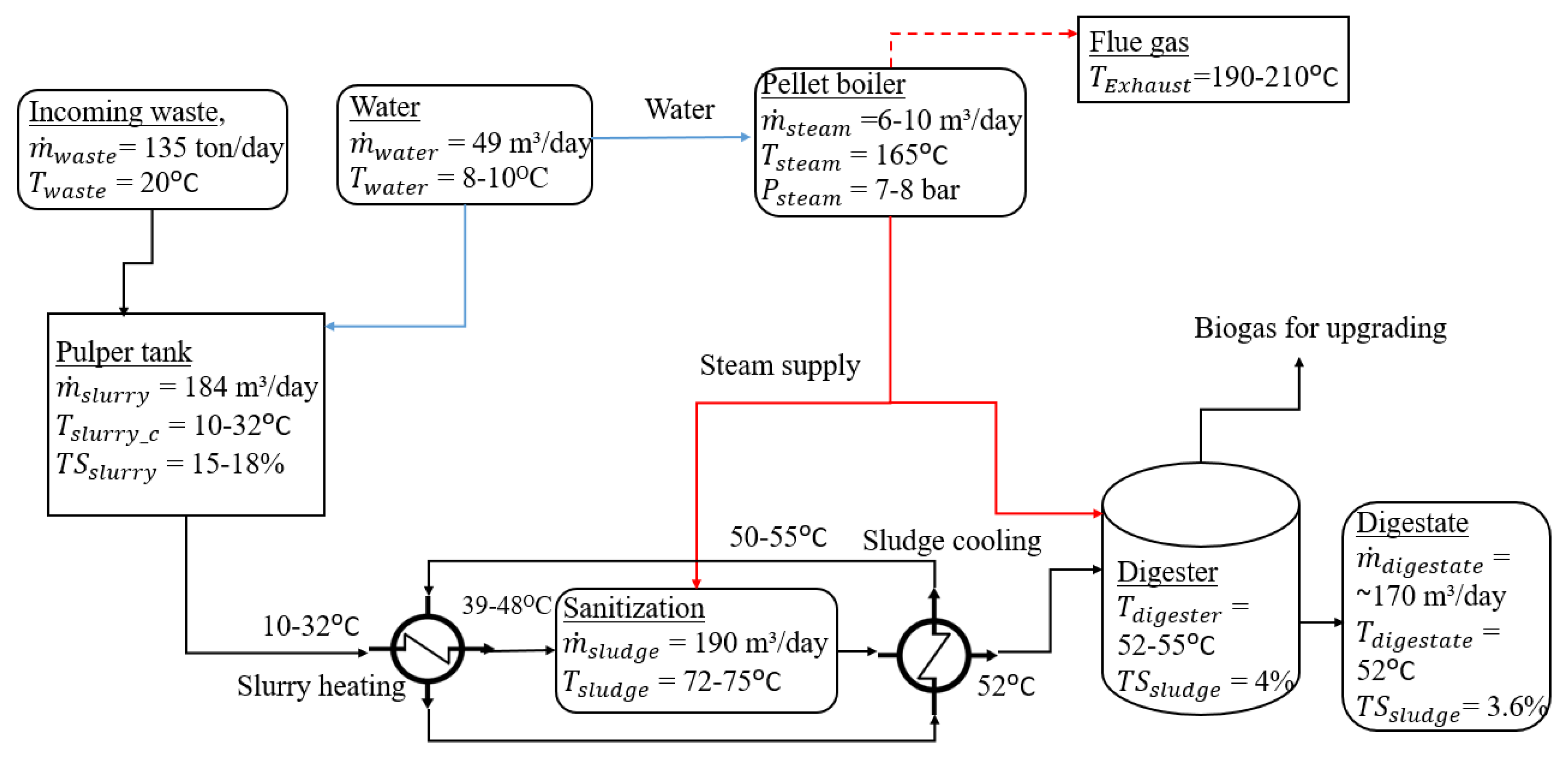
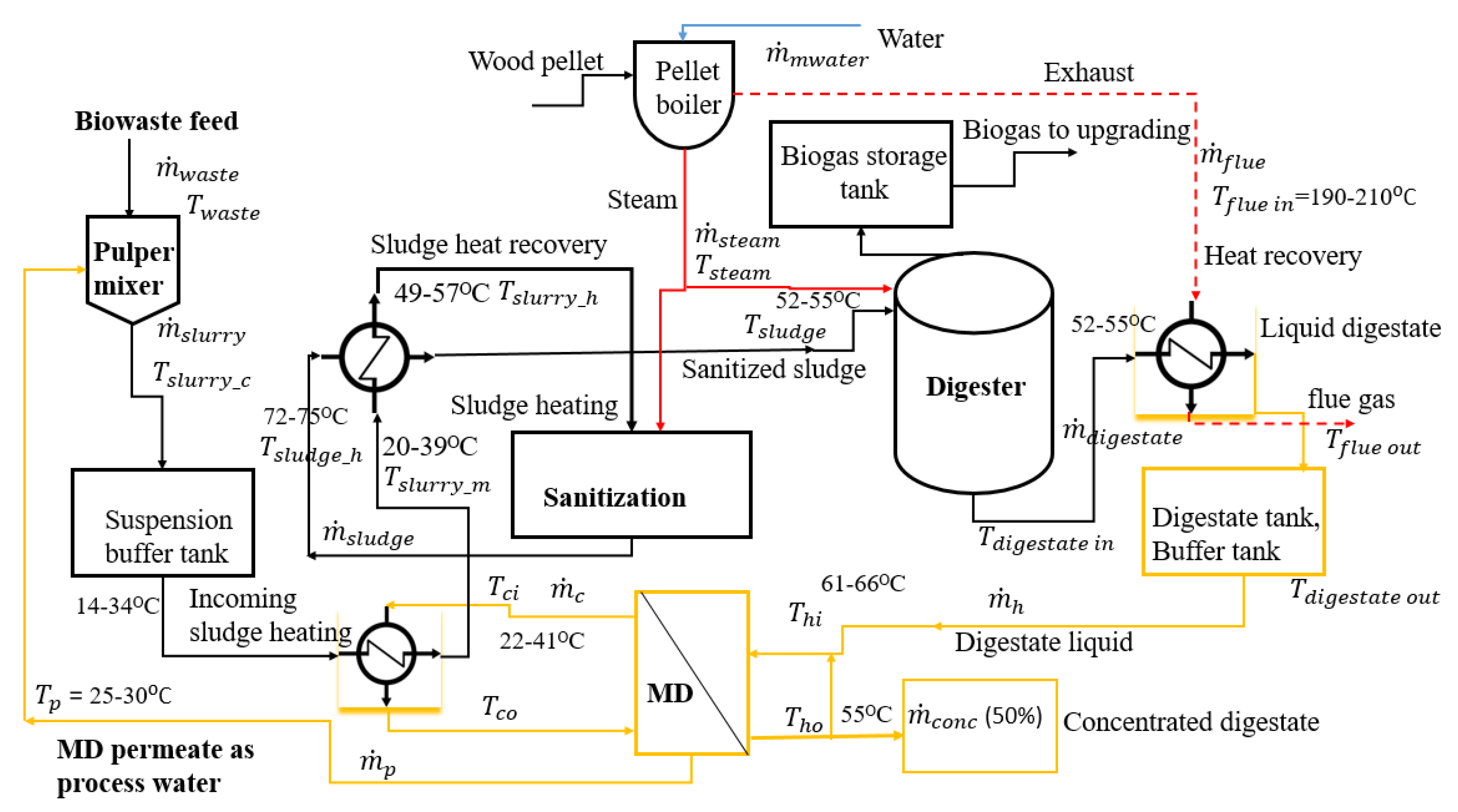
2.1. Uppsala Vatten och Avfall Biogas Plant

The biogas production system was defined based on a survey of commercial AD biogas plants, presented as a simplified flow diagram of the biogas production system (Figure 1). The AD plant, operated by Uppsala Vatten och Avfall AB, Sweden, produces biogas and digestate from mixed organic wastes consisting of source-sorted organic fractions of municipal solid waste (SS-OFMSW, ~82 wt%), food waste (~3 wt%), and slaughterhouse waste (~15 wt%), which is digested under thermophilic conditions (52 °C). The SS-OFMSW and food wastes are pre-treated in a Haarslev waste food de-packer for the removal of plastics and other inorganic wastes. The slaughterhouse waste is added and the substrate is passed through two pulpers, where water is added for dilution and the particle size is reduced to <10 mm. The pulped waste is stored in two holding tanks before passing through a disperser and a step screen, removing plastics and other contaminants. Thereafter, the substrate enters the buffer tank and then the sanitization (pasteurization) process (Figure 1). Heat is supplied by steam from a pellet boiler. Pathogenic microbes are eliminated in the sanitization process, by heating the suspension system to 72 °C for one hour. After sanitization, the outgoing suspension is heat-exchanged with the incoming substrate suspension to achieve 52 °C. The suspension sludge is then pumped into the two parallel digesters with working volume 2200 and 2400 m3. The temperatures of the digesters are kept at 52–55 °C through heat exchange and steam supplied by the pellet boiler. The major characteristics of the existing biogas plant are shown in Table 1.

2.2. Digestate Characteristics

The effluent digestate passes directly to the digestate storage and does not undergo any further treatment after digestion (Figure 1). The average TS content in the digestate is 4.0%, while the average nutrient content of the digestate during the study period is shown in Table 2. The digestate has an N:P:K ratio of 9:1:3, and is used as an organic fertilizer in agriculture.
The mass of digestate produced was calculated by subtracting the mass of biogas from the incoming feedstock. The mass of biogas was calculated based on the biogas composition (60% CH4, 40% CO2) and densities (CH4 0.72 kg/m3, CO2 1.96 kg/m3).

2.3. Overall Thermal Energy Demand Assessment of the Existing Biogas Plant

To map the energy demand of the existing biogas digester, the system was considered as a whole. The energy supplied to the boiler is used in principle for two purposes, sludge sanitization and digester heating. Heat losses occur in heat exchangers, sanitization vessels, digesters, and pipelines, but these were not explicitly investigated. In order to calculate the amount of energy required to produce the steam, the steam flow rate, temperature, and pressure in the steam line were identified. In the thermal heat assessment, the heat demand of the biogas production system during both winter and summer conditions was considered. Based on previous findings [35], the major heat demands were expected to be for the sanitization process, digester heating, and heat losses.

2.3.1. Mass and Heat Balances

Mass balance was estimated for the AD biogas plant by taking account of all material flows shown in Figure 1. The mass balance is based on the fact that the total feedstock is equal to the total digestate and biogas. In the AD digester and biogas production process, it is critical to achieve a water balance. The water balance in the AD system was estimated using Equation (1), in which the incoming water in the AD plant, i.e., water confined in the raw substrates ( m ˙ s u b s t r a t e w a t e r ), from the make-up ( m ˙ m w a t e r ) and steam generated from the pellet boiler ( m ˙ s t e a m ), should equal the outgoing water from the digester, i.e., moisture leaving with raw biogas ( m ˙ b i o g a s   w a t e r ) and water in effluent digestate ( m ˙ d i g e s t a t e   w a t e r ):
m ˙ m w a t e r + m ˙ s t e a m + m ˙ s u b s t r a t e w a t e r = m ˙ d i g e s t a t e   w a t e r + m ˙ b i o g a s   w a t e r
where m ˙ is the mass flow for a specific material flow (kg/h).
The heat balance in the digestion process is required to maintain a constant temperature inside the digester, for substrate sanitation, and for the compensation of heat losses from the tanks and pipe system (Equation (2)). The heat balance of the AD system was stated as:
Q ˙ s a n i t i z a t i o n + Q ˙ d i g e s t e r + Q ˙ b i o r e a c t i o n = Q ˙ d i g e s t a t e + Q ˙ l o s s
where Q ˙ d i g e s t e r is the heat necessary for the digester (kW), Q ˙ s a n i t i z a t i o n is the heat from sanitization slurry (kW), Q ˙ b i o r e a c t i o n is the digestion reaction heat (kW), Q ˙ l o s s is the system heat loss (kW), and Q ˙ d i g e s t a t e is the digestate effluent heat loss (kW).
The five main sub-steps (suspension, heating and heat recovery in the heat exchangers, sanitization, digestion, and water recycle) were assessed for the thermal energy loss from the AD biogas plant. The general thermal energy loss was exemplified by Equation (3):
Q ˙ l o s s = Q ˙ b i o g a s + Q ˙ l o s s d i g e s t e r
where Q ˙ l o s s is the total thermal energy loss from the AD plant.
The heat energy ( Q ˙ b i o g a s ) loss of moist biogas was calculated as (Equation (4)):
Q ˙ b i o g a s = m ˙ b i o g a s ( c p , b i o g a s ( T + 273 ) + x w a t e r h s t e a m )
where m ˙ b i o g a s is the flow rate of biogas,   x w a t e r is the mass percentage of wetness in the biogas, h s t e a m = 2505 − 2.388 T (where T is temperature (K)), and c p , b i o g a s is the specific heat of raw biogas ( c p , b i o g a s = 1.53 k J k g K).

2.3.2. Sanitization/Pasteurization Energy Demand

Sanitization/pasteurization is the main thermal energy-consuming stage in the AD process [36]. Incoming slurry is pumped from the buffer tank to the three parallel sanitization vessels via two heat exchangers. Each sanitized batch (8 m3) is divided between the digesters and fed consecutively with a flow rate of 7.8 m3/h and 8.3 m3/h. The batches are dispersed consistently over the day and each digester is fed approximately 65 m3/day, giving a complete feeding time of 8.3 h/day per digester. All heat is delivered by a pellet boiler (VEÅ Univex P16PD H-16, 1000 kW). For sanitization, steam is added directly to the sanitization tanks. In the first step, the slurry to the tanks is heat-exchanged with newly sterilized slurry before the latter is pumped into the digester. This is done to decrease the heating requirement for incoming slurry and also to avoid overheating the digesters. In this case, efficient heat exchange plays an important role in increasing the overall energy utilization performance. The heat exchangers are counter-current tube heat exchangers, where a water circuit transfers the heat from the warm to the cold side. Some of the steam is used to compensate for heat losses in the digesters and to keep the temperature stable at 52 °C. Total heat supply to the sanitization tank is calculated by Equation (5):
Q ˙ s a n i t i z a t i o n = m ˙ s l u d g e c p s l u d g e ( T s l u d g e T s l u r r y _ h )
Heat recovery from sanitized sludge through incoming substrate is calculated by Equation (6):
Q ˙ r e c o v e r y = m ˙ s l u r r y c p s l u r r y ( T s l u r r y _ h T s l u r r y _ c ) = m ˙ s l u d e c p s l u d g e ( T s l u d g e _ h T s l u d g e )
where c p s l u d g e is the specific heat of sludge and c p s l u r r y is the specific heat of slurry, equal to the specific heat of water ( c p s l u d g e and c p s l u r r y = 4.187 kJ/kgK).

2.3.3. Mapping Steam Supply to the Sanitization Tank

The steam used in the sanitization process is fed directly into the sanitization tanks and therefore cannot be returned to the process. Under the assumption that no leakage occurs, the only mass loss occurs to the sanitization process. The theoretical energy flow to the sanitization process was calculated as follows (Equations (7) and (8)):
Q ˙ s t e a m = m ˙ w a t e r _ b c p w a t e r ( T 165 T w a t e r ) + m ˙ s t e a m ( h 165 h s t e a m )
and
Q ˙ h y g e n i s a t i o n = Q ˙ s t e a m
where T 165   and   h 165 are the boiler water temperature and enthalpy at 165 °C, respectively.

2.3.4. Digester Heating Demand

In calculating the amount of heat given to the digester, the heat supplies measured were the heat losses of the digesters ( Q ˙ l o s s d i g e s t e r ) and the heat required for increasing the incoming slurry temperature. The digester thermal energy losses were calculated based on [32], assuming losses from the slurry to the surroundings, using the following equation (Equation (9)):
Q ˙ l o s s d i g e s t e r = k o u t A o u t ( T d i g e s t e r T o u t ) + k c s A g r ( T d i g e s t e r T o u t ) + k c w A g r ( T d i g e s t e r T o u t )  
where A g r is the digester surface area in contact with the ground (m2),   A o u t is the digester surface from sludge to open air (m2), k c s is the heat transfer coefficient through the ground walls from the inside sludge to soil (W/m2K), k c w is the heat transfer coefficient from the inside sludge to groundwater (W/m2K), and k o u t is the heat transfer coefficient through the walls from the inside sludge to outdoor air (W/m2K).
The heat needed to raise the sludge temperature to the operating temperature (in our case, ~55 °C) was calculated as Equation (10):
Q ˙ d i g e s t e r = m ˙ s l u d g e c p s l u d g e ( T d i g e s t e r T s l u d g e )

2.3.5. Waste Heat Available in Effluent Digestate and Boiler Flue Gases in the Biogas Plant

Considerable amounts of waste heat (energy) could be recovered from the digestate, although the quantitative contribution is unclear. Heat transfer performance depends on the properties of the internal working fluid, i.e., the higher the viscosity, the lower the heat transfer efficiency. For the digestate slurry, the apparent viscosity depends on its mass flow rate [34]. The waste heat available in effluent digestate sludge ( Q ˙ h e a t   d i g e s t a t e   s l u d g e ) was calculated as:
Q ˙ h e a t   d i g e s t a t e   s l u d g e = m ˙ d i g e s t a t e c p d i g e s t a t e ( T d i g e s t a t e   i n T d i g e s t a t e   o u t )
Up-to-date pellet boilers reach efficiencies of 85–89% and wood chip boilers reach 73–81% based on the gross calorific value [37]. However, the annual efficiency of the pellet boiler in the Uppsala Vatten och Avfall AB plant is only approximately 60%. The combustion efficiency, which is around 80%, only describes the efficiency at combustion, and thus does not take into account heat losses to the environment [36]. Nonetheless, pellet boilers have such losses, which mainly originate from the heat energy of the flue gas, which leaves the pellet boiler at temperatures of up to 210 °C (at full load operation), depending on the boiler type [38]. The boiler in the Uppsala Vatten och Avfall plant operates under a constant pressure of 7–8 bar and supplies steam. The pellet boiler’s efficiency, including flue gas sensible heat loss, was measured in this study. In this study, it was assumed that the available sensible heat in the flue gas was recovered via a heat exchanger. A key component in waste heat recovery is the heat exchanger, which captures unused heat from flue gases. The hot exhaust flue gases flow on the exterior of the heat exchanger and transfer heat to relatively cold water. A counterflow heat exchanger is simple in design and provides the most thermally effective arrangement for the recovery of heat from exhaust flue gases. In the present analysis, a B5/Dx36 SWEP brazed plate heat exchanger is considered [16]. Flue gas heat recovery ( Q ˙ f l u e   g a s ) was determined by Equation (12) as:
Q ˙ f l u e   g a s = m ˙ f l u e c p f l u e g a s ( T f l u e   i n T f l u e   o u t )
where m ˙ f l u e   g a s is the flue gas flow rate, c p f l u e g a s is the specific heat of flue gas, and T f l u e   i n and T f l u e   o u t are the flue gas inlet and outlet temperatures, respectively.

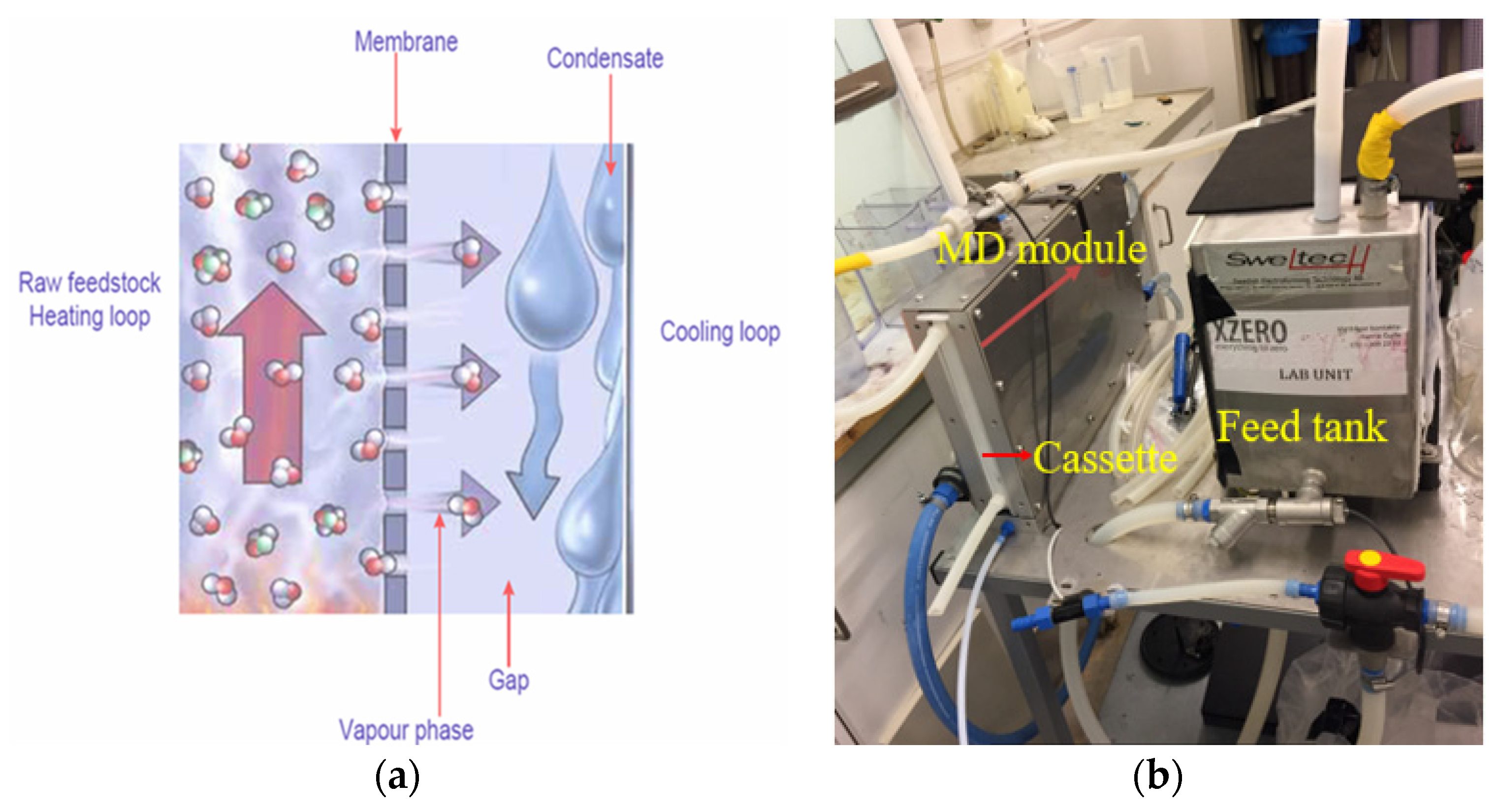
2.4. Membrane Distillation and Its Performance

The permeate (product water) yield in the MD process increases with the increasing difference in temperature between the module feed and cooling channel. An increase in flow rate increases the permeate yield in a linear trend [2,11]. Laboratory-scale MD unit performance data (Figure 2) (such as the separation efficiency, permeate production rate, and specific thermal energy demand) used in the present calculations were taken from previous studies [2,11]. The experiment was run for three consecutive days in order to obtain the small-scale lab unit MD’s performance results. The total amount of permeate production for a given heat recovery level in the AD system integrated with the MD unit was estimated by using the reported performance data [2,11].
At the Uppsala Vatten och Avfall biogas plant, the sizing of the full-scale MD module was based on the available waste heat recovery achieved. The MD permeate flux estimation was considered from previous experimental studies [2,11].
Experimental data from a laboratory-scale MD unit and pilot-scale study were used to analyze the specific thermal energy demand (STED) of the MD [2,11,40]. The MD coolant side (Figure 2) heat recovery through incoming slurry was considered in the net heat energy calculation. Moreover, there is a small amount of convection and conduction heat loss via the MD permeate and module surfaces to the surroundings. A minor amount of MD pump electricity (kWh) is necessary for feed digestate and coolant flow. Detailed calculation procedures for the MD heat losses and pump electricity consumption were considered in this study.

2.5. Thermal Integration of AD–MD (Use of Available Low-Grade Waste Heat for MD, Process Integration, and Mass and Energy Calculation)

The integrated AD–MD approach was intended to improve the thermal energy efficiency and the water balance at the biogas plant by:
(1)
Utilizing the potential of waste heat available from the existing biogas system (thermal characteristics of waste heat sources) for MD operation;
(2)
Assessing the thermal characteristics of the AD biogas production system (sink for waste heat);
(3)
Recovering flue gas heat from the pellet boiler via a heat exchanger, to heat the digestate from an initial 52 °C to 66 °C and 61 °C in the winter and summer season, respectively, before MD;
(4)
Recovering waste heat from the MD cooling channel via a heat exchanger to preheat the substrate suspension;
(5)
Replacing the tap water used for substrate dilution with permeate from the MD unit, which has a higher temperature than tap water;
(6)
Concentrating the effluent digestate two-fold through MD.
In the integrated AD–MD system, waste heat recovered from the digestate and the pellet boiler flue gas system is re-used in an MD unit, and the permeate from the MD unit is used as process water for the AD system, thus replacing the feedstock dilution water and boiler make-up water (tap water) (Figure 3). The digestate sludge heat recovery unit mainly comprises a heat exchanger, which is attached to the boiler exhaust gas line to capture the waste heat. Incoming feedstock is pre-heated by the MD cooling side through the heat exchanger, and further heated in the sanitization and digester. This reduces boiler energy consumption and increases net energy production in the system. The digestate sludge is separated by the MD unit and the liquid fraction (permeate) is sent to the water tank, which is recirculated into the pulper mixer. The retentate, as concentrated digestate from the MD unit, leaves the system for storage before application to agricultural land.
Two seasonal cases (winter and summer) were defined here for the calculation of thermal integration, to represent the different thermal energy capacities of AD plants. It was assumed that the waste heat generated from the outgoing digestate only depends on the digestate flow rate and temperature, and not on the season, while the heat recovery from boiler flue gases depends on seasonal temperature variations. The heat features of the MD process (sink for waste heat) and the anticipation of waste heat recovery were evaluated by the temperature differences for the key streams (such as feed digestate and flue gas) of the processes described in this study. It was considered that the minimum temperature necessary for waste heat utilization should be higher than the available temperature in the MD inlet feed digestate.
A pinch point study [41] is the most commonly used approach for internal thermal integration to recover waste heat and improve the overall thermal efficiency of a process. Therefore, it was applied in this study, and the pinch temperature for heat exchangers was set to 5 °C. The MD feed digestate temperature after the heat exchanger may vary, depending on the available waste heat from the digestate sludge line and the flue gas flow rates and temperatures.
In the present study, the two-stage cascaded MD module arrangement presented elsewhere [42,43] was considered for scaled-up performance, with 10 cassettes per module (two or more cassettes placed in parallel), with total heat energy input, feed digestate, and coolant (incoming slurry) flow rates adjusted proportionately. For a specified temperature difference across the MD module, the total number of cassettes was estimated by the amount of waste heat available. The scaling-up method for the integrated MD module for an industrial biogas plant was considered in this analysis.

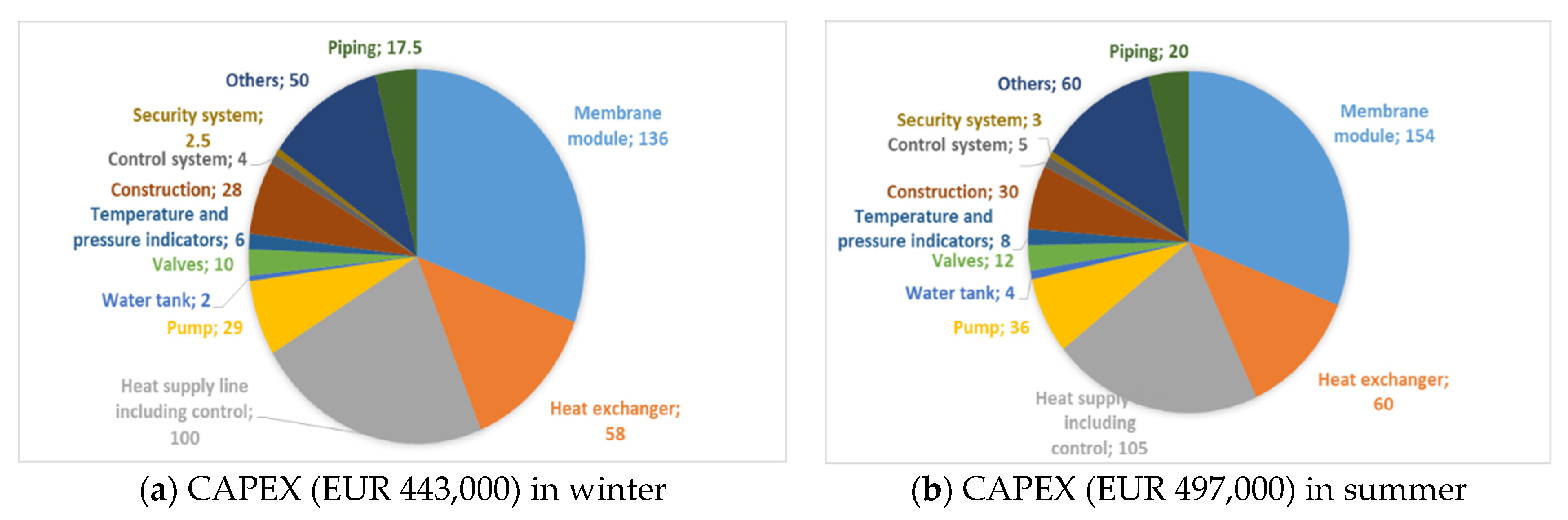
2.6. Technical Requirements and Cost Determination for the Integrated MD System

The cost of AD–MD thermal integration is a critical issue, especially for heat recovery from low-temperature heat sources. Both the technical and cost-effective aspects must be taken into account, for the assessment of the viability of the integrated AD–MD technology at an industrial scale. For estimating the costs for a full-scale AD–MD integrated system, the capacity method was used in [44]. This cost estimation methodology was also used in our study. For the projected commercial-scale MD system in this study, the cost estimations were provided by Xzero AB (subsidiary company of Scarab Development AB) [39], based on the economics of pilot-scale MD plants used in preceding studies [17,42].
At this point, the cost and benefit changes due to the thermal integration of MD were considered, including waste heat utilization, recovered water recycling in the biogas plant for feedstock dilution, and the concentration of nutrients from the digestate (reducing the volume by 50%).
The major parameters applied during the economic assessments of MD were capital expenditure (CAPEX), operating and maintenance expenditure (OPMEX), and MD product water (permeate) cost. The economic lifetime of the capital investment in the full MD unit was set to 20 years. These CAPEX costs were then distributed over the amortization period n of the MD plant, assuming a fixed interest rate z and capital expenditure, to give the annual C A P E X ( Σ C A P E X ):
Σ C A P E X = z ( 1 + z ) ( 1 + z ) 1 C A P E X
An interest rate of 5% was assumed for the planned economic model, since this interest rate is stated for conventional desalination plants in the literature [42,45].
The OPMEX of the MD unit comprises the energy requirement, chemicals for membrane cleaning, maintenance, insurance, and replacement of the membranes. No external heat energy is needed if the recovered waste heat is sufficient to run the full-scale MD. However, the unit cost of heat energy was 0.05 €/kWh. Moreover, the cost of the electricity required for the pumps was set to 0.06 €/kWh [6,46] in this study.
In order to decrease the pH of the feed inlet digestate from 8.0 to 5.0, and to clean the membrane surface to prevent fouling, diluted acid is necessary [2]. The total annual operating and maintenance expenditure, Σ O P M E X , is the sum of all annual costs listed above. Finally, the specific cost ( C p w ) of MD permeate (€/m3) includes all the yearly expenditures (CAPEX and OPMEX) divided by the total annual MD permeate production ( M ˙ p ):
C p w = ( Σ C A P E X + Σ O P M E X ) / M ˙ p
Different cost data (mainly internal energy cost, maintenance costs, and transportation costs) were assessed based on data for a Swedish biogas plant [47].
In this study, laboratory and pilot-scale MD results were used for predicting the techno-economic performance in a full-scale integrated AD–MD plant, so some uncertainty obviously exists. Therefore, a sensitivity analysis was performed on the most significant cost variables identified, to evaluate the impact of changes in these on the economic consequences.

3. Results and Discussion

3.1. Mass and Heat Balance for the Existing Biogas Plant

The mass and heat flow of each stream during summer and winter are shown in Table 3 and Figure 4. There was a significant difference in the heat requirement between summer and winter (Equation (10)) (Table 3). The influent slurry temperature range varies significantly between winter (approximately 10 °C) and summer (approximately 32 °C), which obviously has a substantial effect on the thermal energy consumption of the plant (Figure 4). The thermal energy required for raising the influent slurry to the working temperature accounts for around 75% and 85% of the total heat requirement during summer and winter, respectively (see Table 3). This resulted in variations in waste heat recovery between summer and winter. Obviously, the feeding heating load is a key part of the total digester heat demand. Hence, it is necessary to pay more attention to the feedstock heating load, to ensure that the working temperature remains stable. Apparently, in the digestion process, there are some heat losses that occur, and the estimated thermal energy losses were as follows: thermal energy losses from the sanitization and digester units were estimated (Equation (3)) to be 15% of the total heat demand [30,31] of the digestion process. These thermal heat losses are dependent on the digester scheme and the temperature difference between the inside of the digester and the outside surroundings. In the mass analysis, it was considered that the volume of the effluent digestate from the digester accounts for 87% of the incoming substrate to the biogas AD plant, whereas 13% of the substrate is converted into biogas.
In the sanitization tank, the temperature is raised from ~ 45 °C to ~ 72 °C by means of water vapor (see Equations (5) and (7)). The sanitization process moves between the three tanks. When the first tank is ready, the next is filled and heat exchange can take place between the two tanks (Equation (6)). The sequence continues between the three tanks and excess heat is utilized in this way. The data in Table 3 suggest that the energy demand was nearly constant for the entire period, but that the energy consumption depended strongly on the season. The total slurry flow rate was also higher in winter than in summer, because the steam supply to the sanitization tank and digester was higher in winter. The energy calculation showed that the net heat energy needed for sanitization in winter was 40% higher than in summer. Moreover, it showed that the seasonal variation was more significant for the pellet boiler energy supply (66% higher in winter).
The energy balance calculation demonstrated, for the existing thermophilic digester, that the course of energy consumption has a higher dynamic than the course of energy production. The sanitization process and the digester itself consume the majority of the heat produced.
There is a significant amount of waste heat in the flue gases and effluent digestate (Equations (11) and (12)), but the amount available varies between winter and summer operation depending on the thermal energy consumption by the plant (Figure 4 and Table 3).

3.2. Integrated Performance of AD–MD Assessment

The results presented below for AD–MD thermal integration are based on steady state conditions of the system. The heat energy consumption of the sanitization process for the reference biogas plant currently requires approximately 12,790 kWh/day in winter and 8324 kWh/day in summer (see Table 3). Thermal energy analysis showed that, conceivably, 90% of the available waste heat from the effluent digestate and flue gas can be recovered (Figure 5). The heat energy calculation showed that the MD unit thermal energy consumption could be fully met by the recovered waste heat. Table 4 summarizes the energy flow for the main streams of the integrated AD–MD system under the conditions of sanitization at 72–75 °C for one hour in both summer and winter, and the main characteristics and results of thermal integration. Two factors were found to have significant impacts on thermal integration, namely the sanitization operation conditions and ambient conditions. Net thermal energy consumption was reduced by up to 17% due to the reduction in internal energy consumption through thermal integration. The integrated AD–MD system significantly increased water utilization through (1) recycling the raw digestate water and (2) sharing the process water.
The most encouraging outcome was the high waste heat recovery rates attained from comparatively low-quality waste heat sources through AD–MD thermal integration. This was mainly due to the heat characteristics of the biogas digestate and the working temperatures of the MD technology, i.e., the temperature range of the waste heat complemented the heat demand of the MD. The heat recovery rate from the integrated system was found to be highly dependent on the sanitization and ambient conditions. During winter, the waste heat from digestate and flue gases was mostly (90–95%) utilized by the MD unit. During summer, the waste heat recovery rate fell to 64–85%, depending on the sanitization situation (see Table 4 and Figure 5). The higher waste heat recovery rates in winter were obtained because more heat was necessary for sanitization at 72 °C for one hour. A significant amount of the heat in flue gases was recovered, with the recovery rate being 44% higher in winter than in summer. The energy saving from biogas production with thermal integration was reflected by the lower internal use of steam from the pellet boiler for heating (Table 4).
The mass balance calculations were based on the mass flow of incoming feedstock (food and slaughterhouse wastes, diluting water, and boiler make-up water) and added chemicals, the biogas flow rate, and the effluent digestate flow and its characteristics. Since dilution water is needed to dilute the incoming feedstocks to the plant, and make-up water is needed for the pellet boiler for steam production, in this analysis, the digestate liquid was separated out by the MD, and this MD permeate was assumed to be recycled as dilution water and make-up water in the digestion process. The permeate recovery from effluent digestate by MD through the thermal integration of AD–MD can provide a better water mass balance for the overall system (see Figure 5), and fully replaced the dilution and make-up water for incoming substrates’ dilution and pellet boiler steam production purposes. On the other hand, recycling the MD permeate for substrate dilution had a significant impact on the influent slurry temperature, especially in winter conditions (see Figure 5). The digestate separation/concentration MD technology concentrated the effluent digestate by two-fold (Table 5). Concentration of the digestate feed with MD by 50% of the primary incoming substrates, nitrogen was converted into ammonium nitrate (approximately 6000 mg/kg). Moreover, in the MD feed side digestate retentate, the nitrogen concentration was approximately 9000 mg/kg, compared with 4500 mg/kg in the effluent digestate, while the phosphorus concentration was 1000 mg/kg in the MD concentrated digestate and 500 mg/kg in the effluent digestate, and the potassium concentration was 3000 mg/kg in the MD concentrated digestate and 1500 mg/kg in the effluent digestate.
The temperature of the MD permeate varied from 25 to 30 °C in winter and summer conditions. Therefore, the temperature of the MD permeate is higher than that of municipal piped water (10 °C). Therefore, the heat energy contribution through MD permeate water was significant. The thermal energy analysis (Table 4) showed that the permeate water heat energy input was 1155 kWh/day (15% of total recovered waste heat contribution) and 834 kWh/day (12% of total recovered waste heat contribution) during winter and summer, respectively. The flue gas heat recovery was higher in winter because the pellet boiler was working in full load operation due to high-energy consumption by the sanitization process. Based on Equations (11) and (12), the heat energy required for total slurry heating in the sanitization process after introducing MD was approximately 10,658 kWh/day in winter and 6756 kWh/day in summer (see Table 4), i.e., an approximately 17% reduction compared with the reference Uppsala Vatten och Avfall plant. The sanitization heat demand was 58% higher in winter than in summer. Heat analysis also exhibited that most of the accessible low-grade waste heat (7633 kWh/day in winter, 7067 kWh/day in summer; 8% higher than summer) was recovered by the effective integration of the AD–MD process (Figure 5).
The heat energy calculation showed that 77% and 83% of recovered waste heat added to the MD process in winter and summer (Equations (11) and (12)), respectively (see Table 4), which demonstrates the significance of AD–MD thermal integration and waste heat recovery. Moreover, the heat energy assessment showed that the thermal integration of the AD–MD not only improved waste heat utilization, but also reduced the internal thermal energy consumption (1568 kWh/day in winter and 2133 kWh/day in summer).
The variations in the MD water production rate estimated as permeate at different feed inlet temperatures are shown in Figure 6. It was assessed that the permeate production rate increased significantly with increasing feed inlet temperature. The maximum digestate and flue gas exhaust temperatures can be obtained in winter conditions compared to summer (Figure 6). Thus, the permeate production rate varied with the feed inlet temperature and it is higher in winter conditions (Figure 6).

Specific Thermal Energy Demand by Membrane Distillation

Heat energy values obtained in a previous study on a laboratory-scale MD unit [2] were scaled up for a full-scale MD unit in the thermal integration method for continuous digestate feed and coolant (sludge) flow rates, as summarized in Table 5. The specific thermal energy demand (STED) of MD is in the order of ~800 kWh/m3 and 1050 kWh/m3 at a feed digestate inlet temperature of 66 and 61 °C in winter and summer, respectively, if no heat recovery is obtained from the MD cooling side via incoming slurry heating, but the STED is reported to be relatively lower with a higher feed inlet temperature [2,11,48]. In the present analysis, the average STED (including MD coolant heat recovery) value was considered to be 80 kWh/m3 in winter and 100 kWh/m3 in summer. The electrical energy (see Table 5) needed for the pumps in a full-scale MD process depends on the number of membrane modules, feed and coolant flow rates, and pressure drop, etc. The average pump electricity demand considered in this study was 1.60 kWh/m3. The overall thermal energy balance showed that the recovered waste heat was sufficient to run the full-scale MD. Thus, additional heat would not be required if MD was integrated in full-scale operation. Furthermore, the total heat loss assessment found that more heat transfer to the MD module shields and permeates at a higher MD feed and coolant temperatures. Some recent studies have shown that, by reducing the overall heat losses of MD, a lower specific heat demand can be achieved [42,49,50].
Using the comprehensive data about thermal energy demand and supply provided in Figure 5, the overall performance (feed digestate inlet and outlet temperatures, digestate feed flow, coolant flow, and permeate production rate, etc.) of the full-scale MD was calculated (Table 5). However, the total specific thermal energy demand for MD was still 5500 kWh/day in summer and 3500 kWh/day in winter. The maximum capacity of feed digestate flow for the MD was 2.7 m3/h/module and the total number of modules was 234 in winter, but 264 in summer (as the MD feed digestate temperature was lower in summer). The total permeate production rate was approximately 55 m3/day with the full-scale operation of MD. If the digestate feed flow rate to the MD module is fixed, permeate production can be optimized to increase the temperature difference between feed digestate and coolant temperature and adjust the number of membrane modules required, thereby also decreasing the total energy demand.

3.3. Economic Assessment of the Integrated AD–MD System

In low-grade heat-driven MD applications, both capital expenditure (CAPEX), and operating and maintenance expenditure (OPMEX) costs are largely influenced by waste heat utilization, product water recovery, and the effective integration of MD. The costs of detailed components and other essential parameters of the integrated AD–MD system are shown in Figure 7. The cost analysis calculations showed that the CAPEX was approximately EUR 443,000 and EUR 497,000 for the full-scale installation of integrated MD for winter and summer conditions, respectively. The CAPEX values of MD were 12% higher in summer because of the need for a larger MD capacity, due to the lower waste heat recovery from the existing biogas plant in summer. It can be observed from the CAPEX estimation that the MD module costs (around 31% of total CAPEX in both winter and summer) and the AD–MD integrated heat supply line including control (around 22% and 21% of total investment in winter and summer, respectively) contributed the highest share of the total CAPEX costs, followed by other investment expenditures (as can be seen from Figure 7). The heat exchangers’ investment cost also represented a significant share of the CAPEX costs.
The OPMEX values for the integrated MD system ( Σ O P M E X ) are summarized in Figure 8 for winter and summer. The previous studies [17,42] reported that the thermal energy cost made the highest contribution to the total OPMEX for the integrated MD system. As can be seen from above the energy balance, the MD can run with recovered waste heat from the biogas plant, so no thermal energy cost was considered in the OPMEX cost calculation. In this study, it was estimated that the MD module replacement costs made the highest contribution, around 41% for both winter and summer, to the total OPMEX. The costs analysis also exhibited that OPMEX values were lower in winter, when waste heat was utilized in the full-time operation, than in summer. As a result, it can be said that the OPMEX could be affected considerably by waste heat recovery. The heat cost calculation showed that the waste heat recovery could save EUR 58,000 and EUR 91,000 yearly in winter and summer, respectively, which signifies a substantial amount of the total OPMEX of the integrated AD–MD system. Furthermore, MD has emerged as a robust technology and is less likely to undergo severe scaling compared to RO and other membrane technologies; therefore, only light pretreatment of the feed digestate liquid has been considered in the analysis. On the contrary, due to the supplementary costs of the heat streamline, pumps, control system, and heat exchangers, the total CAPEX was higher for the integrated AD–MD system than for the system without heat recovery. Nevertheless, due to the overall lower OPMEX cost of the integrated AD–MD system, these added CAPEX costs can be reimbursed within less than one year. Moreover, the OPMEX of the integrated system can be influenced significantly by the operating parameters of the MD, membrane performance, and waste heat recovery rate.
In this study, the unit cost of MD permeate ( C p w ) for an integrated AD–MD unit with waste heat recovery was 3.6 €/m3 and 4.1 €/m3 at a digestate inlet feed temperature of 66 °C and 61 °C during winter and summer, respectively. Cost analysis showed that the permeate production cost was 14% higher in summer than in winter, due to the lower rate of heat recovery and lower digestate feed temperature in summer. The permeate production cost calculation exhibited that the unit permeate cost in this study was lower than the 5.6 €/m3 and 4.7 €/m3 reported by [17,42], respectively, for a pilot-scale test rig set up at Hammarby Sjöstadsverk, Stockholm, and higher than the 2.2 €/m3 stated by [43] for a test rig deployed at Idbäcken Cogeneration Facility, Nyköping, Sweden, perhaps because of the higher net specific thermal energy demand for MD and the operation and maintenance costs for a challenging digestate feed.

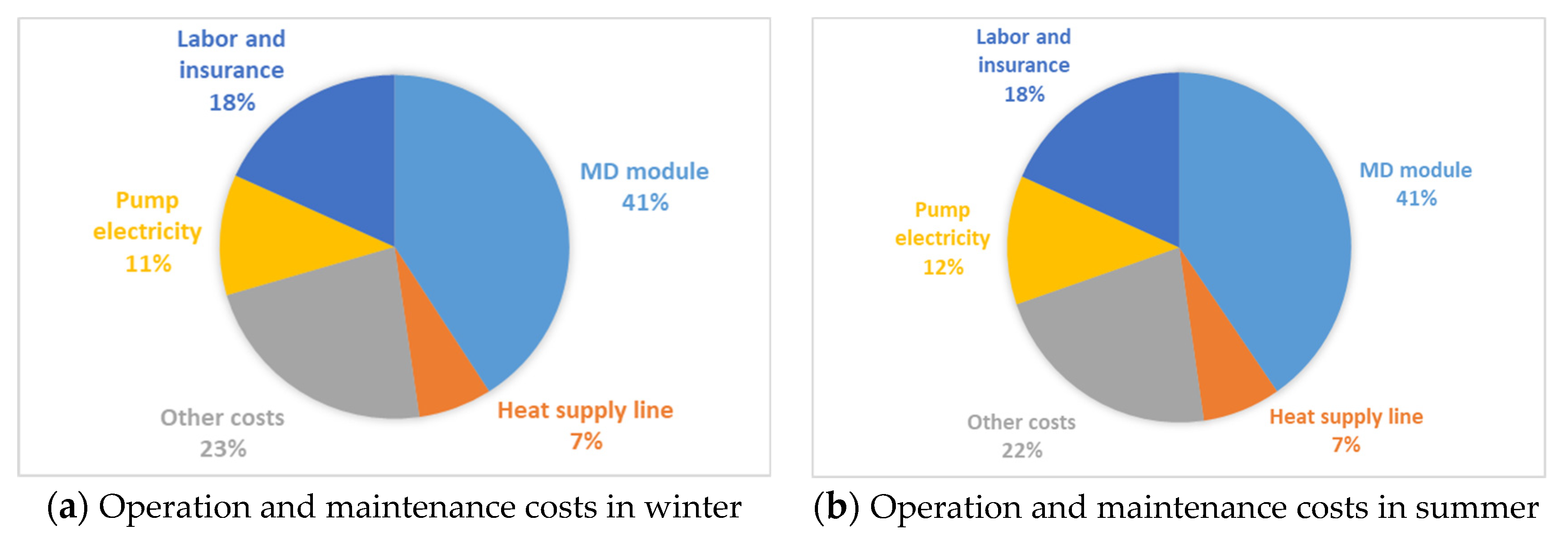
Overall Cost Performance and Sensitivity Analyses at the Integrated MD–AD Plant

The thermal energy analysis showed that the MD heat energy consumption could be met by the available waste heat in the biogas plant. The thermal energy cost analysis showed that it had a significant impact on the permeate production cost for the cases with and without heat recovery, even though the case without heat recovery showed higher sensitivity (Figure 9). The cost of heat energy change of ±15% (keeping all other cost variables constant) would give an MD permeate production cost of 3.6 ± 0.5 €/m3 and 4.1 ± 0.6 €/m3 for the AD–MD integrated system with waste heat recovery in winter and summer, respectively (Figure 9). Moreover, the cost analysis showed that the permeate production cost without heat recovery would be significantly higher, 7.6 ± 1.0 €/m3 (110% higher than with heat recovery) in winter and 9.1 ± 1.1 €/m3 (122% higher than with heat recovery) in summer.
The total costs and benefits for the integrated AD–MD system at the Uppsala Vatten och Avfall plant are shown in Figure 10. Aside from the costs associated with the CAPEX and OPMEX of the integrated AD–MD unit, the total yearly cost would range between 105,000 and 125,000 €/year, taking into account a difference in the heat energy cost of ±20% during summer and winter, respectively.
The concentration of digestate by the integrated MD can considerably decrease the costs for storage facilities, transportation, digestate management, and spreading on the land. The cost saving from concentrating digestate nutrients can thus be substantial, particularly for the biogas plant in Sweden. It was assessed that the annual revenue would range between EUR 350,000 and EUR 210,000, considering the variation between seasons. In the AD plant, feed substrate dilution and boiler make-up water is supplied by the Uppsala municipality, but in the integrated AD–MD system, the MD permeate is recycled for dilution and make-up water purposes. Therefore, additional water costs can be saved by using MD permeate water.
The thermal integration of AD–MD can be a viable alternative in terms of expenditures and benefits. However, available cost data for CAPEX and OPMEX for full-scale integrated MD are limited. However, it is possible to further improve the cost and benefit performance by adopting a thermal energy and MD size optimization approach in the integrated system. It was estimated that a net annual profit of around EUR 85,000 in summer and EUR 250,000 in winter (for the base case situation, i.e., no variation in heat energy cost) could be achieved at the Uppsala Vatten och Avfall biogas plant through the thermal integration of an MD unit.

4. Overall Discussion

The integrated AD–MD process offers the possibility to recycle concentrated nutrients from highly diluted digestate (>90% water content) back to arable land as fertilizer, reducing the storage requirement and transportation costs. A high low-grade waste heat recovery rate was achieved in this study, mainly due to the thermal characteristics of the available waste heat in digestate and boiler flue gas, and the MD unit. Moreover, the MD module cost reduction in the future will contribute to the cost and benefit outcomes. Furthermore, the addition of sulfuric acid to the MD feed digestate during the treatment for pH reduction, and the effects on concentrated nutrients, have to be explored.
However, MD faces some drawbacks, such as low permeate production and high conduction heat loss. Moreover, scale formation (fouling) is witnessed in membrane surfaces when applied to normally challenging feed characteristics, but is significantly lower than in other membrane processes [14,51]. Laboratory-scale MD tests showed that the membrane surface could be cleaned with highly diluted sulfuric acid with good results [2]. The actual membrane and module lifetime should be investigated on at least a pilot scale in long-term testing. In future work, the assumptions made in this study must be validated in practice. Ultimately, detailed engineering of an AD–MD system as described in this work is needed to validate all assumptions made.

5. Conclusions

In this work, cost and performance analyses were conducted for a waste-heat-driven integrated MD for the treatment of digestate liquid, in order to recycle process water, recover low-grade waste heat, and concentrate (by two-fold) the nutrients for bio-fertilizer use. It was found that the waste-heat-driven MD membrane effectively rejected nutrients, which led to their enrichment in the digestate sludge (MD retentate). The following conclusions can be drawn from the current study.
-
Thermal energy analysis of the existing biogas plant showed that the heat energy requirement for bringing the influent slurry to the working temperature accounted for around 75–85% of the total heat requirement. The analysis also showed that the net heat energy needed for substrate sanitization was 40% higher in winter than in summer.
-
The performance of an AD system with thermal integration of MD would thus mainly depend on the operating conditions of the integrated process, especially the substrate sanitization process and ambient conditions (summer or winter).
-
The recovered waste heat from the effluent digestate and boiler flue gas (around 7633 kWh/day in winter and 7063 kWh/day in summer) could meet the total thermal energy demand of MD and can save around 20% of pellet boiler energy by heating incoming slurry.
-
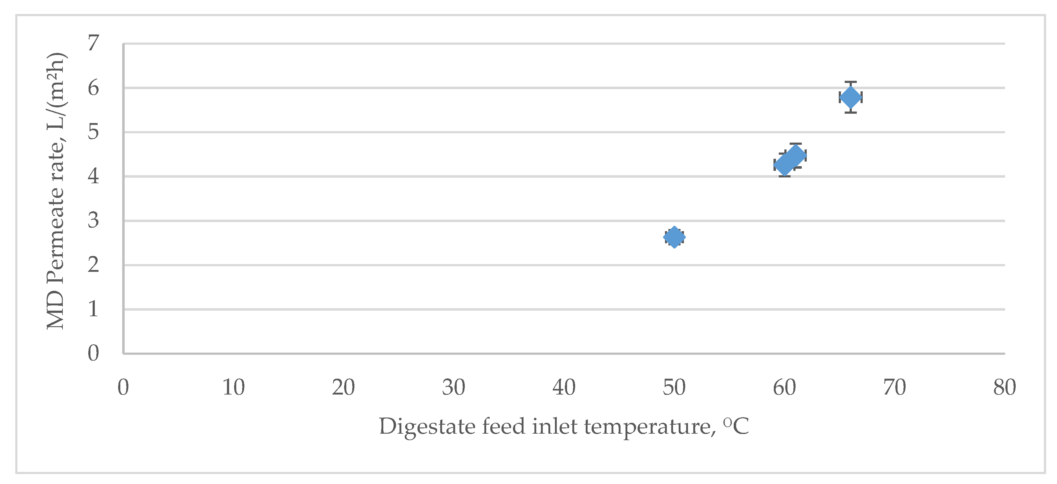
The MD permeate production rate was 3.5 L/(m2h) at 66 °C and 3.1 L/(m2h) at 61 °C digestate inlet temperature, during winter and summer conditions, respectively.
-
When the available heat was recovered from the coolant side of the MD through the incoming slurry, the net specific thermal energy consumption for the MD system was estimated to be 100 kWh/m3 and 80 kWh/m3 permeate during summer and winter, respectively.
-
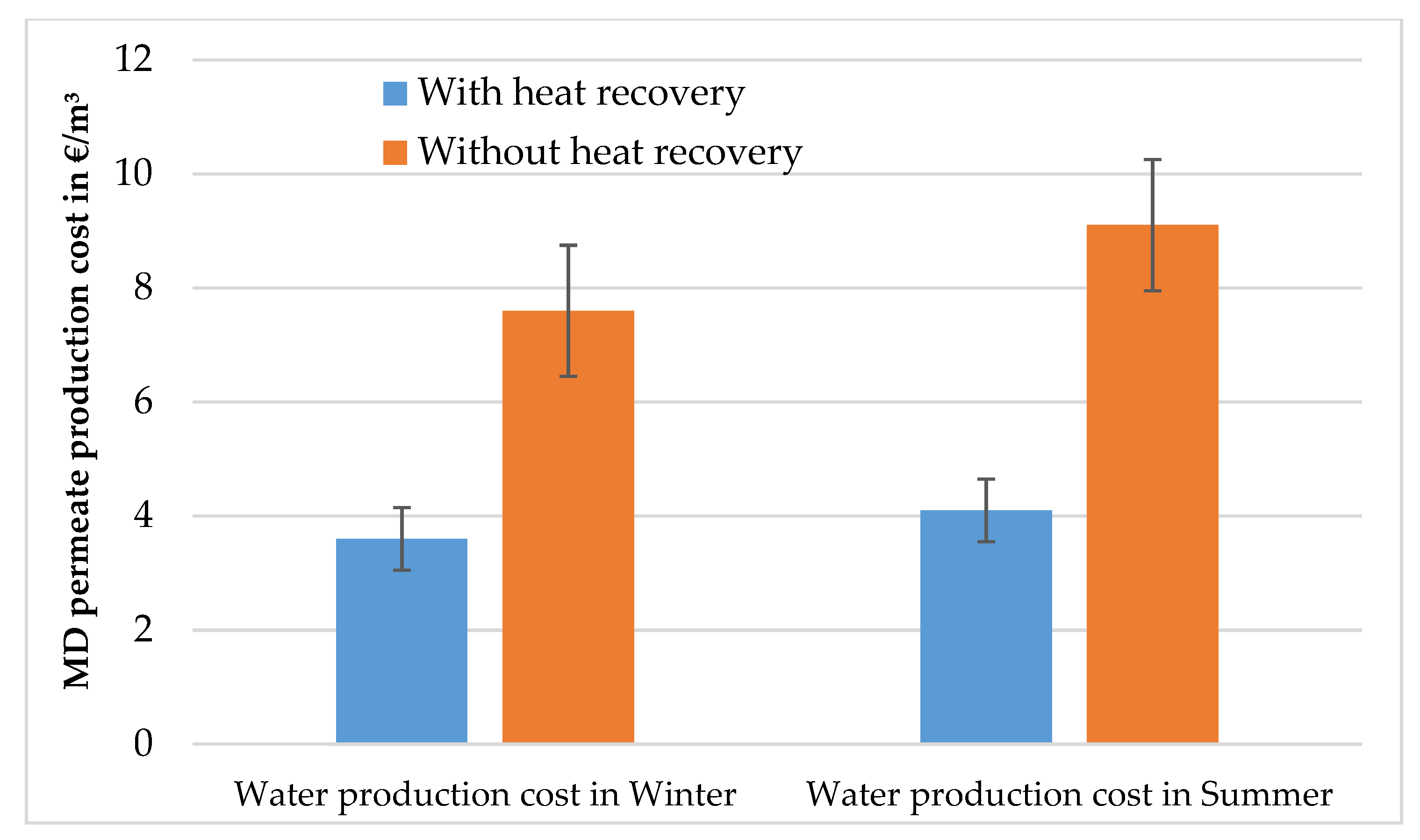
Cost assessments showed that with waste heat recovery, the unit cost of MD permeate production waste heat recovery was 3.6 €/m3 and 4.1 €/m3 at a digestate feed temperature of 66 °C and 61 °C (including waste heat recovery) during winter and summer, respectively. Without heat recovery, the cost was 7.6 €/m3 and 9.1 €/m3 in winter and summer, respectively.
-
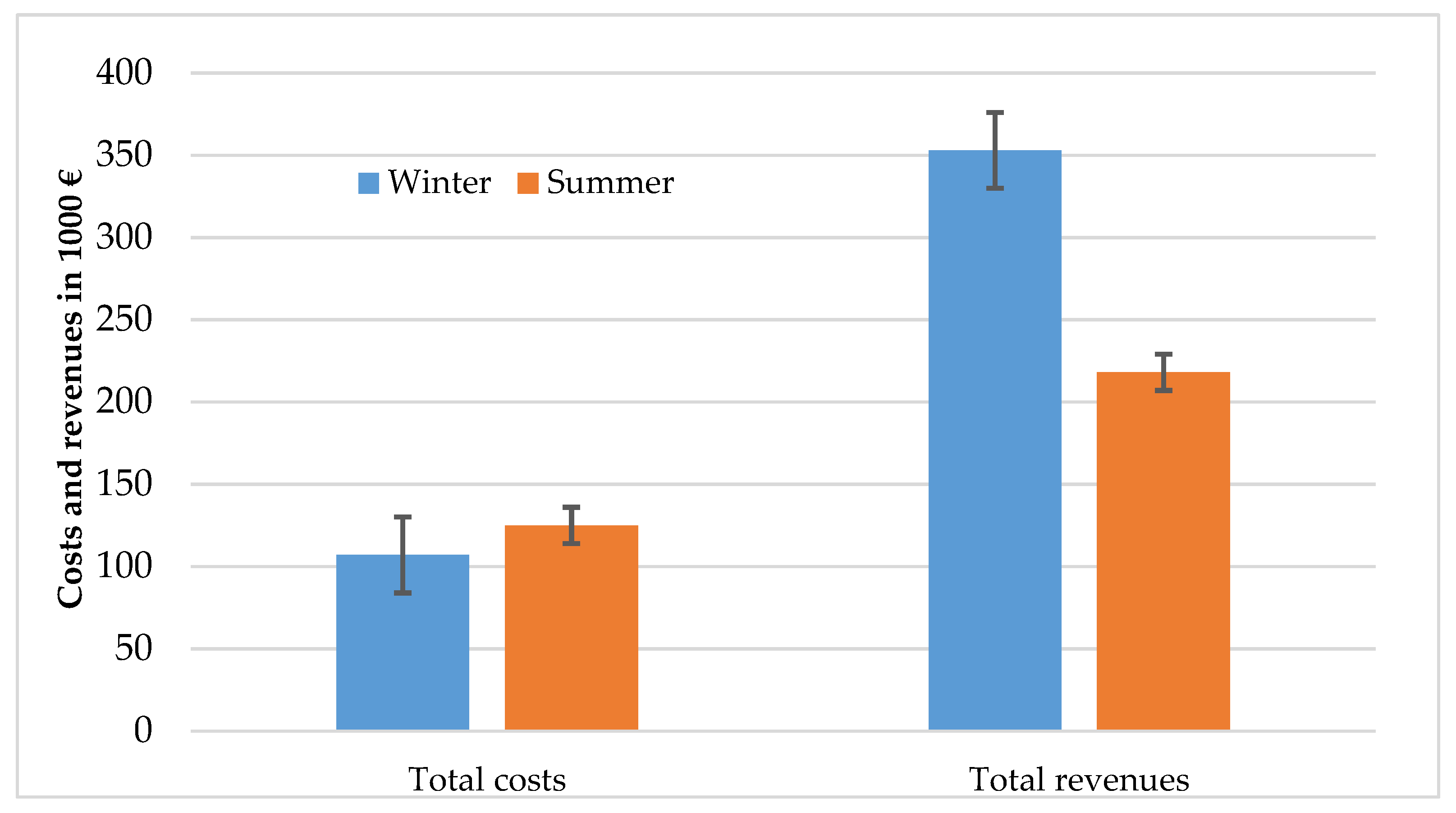
The economic assessment also indicated that the revenues could exceed the total costs, mainly because the MD could be operated using only recovered heat.
-
A net annual profit of approximately EUR 250,000 and EUR 85,000 was achieved for the base case scenario (i.e., no variation in thermal energy cost) in summer and winter conditions, respectively.
-
In order to determine the impact of membrane fouling on MD performance, long-term studies are needed.

Author Contributions

Conceptualization, E.U.K. and Å.N.; methodology, E.U.K.; data curation, E.U.K. and P.M.; formal analysis, E.U.K.; investigation, E.U.K.; resources, E.U.K. and Å.N.; supervision, Å.N.; validation, E.U.K., P.M. and Å.N.; visualization, E.U.K.; writing—original draft, E.U.K.; writing—reviewing and editing, E.U.K. and Å.N. project administration, Å.N. and E.U.K.; funding acquisition, Å.N. All authors have read and agreed to the published version of the manuscript.

Funding

This paper was written within the scope of the BRC (Biogas Research Center, Sweden) research program “Department of Research and Innovation” Project No. 35624-3, funded by the Swedish Energy Agency.

Institutional Review Board Statement

Not applicable.

Informed Consent Statement

Not applicable.

Data Availability Statement

Not applicable.

Acknowledgments

Many thanks to the BRC (Biogas Research Center, Sweden) and the Department of Energy and Technology, SLU-Swedish University of Agricultural Sciences, Sweden, for their partnership in the project. The authors are grateful to Uppsala Biogas Plant, Uppsala Vatten och Avfall AB, Sweden, for helping in the collection of operational data and for kindly allowing us access to their facility.

Conflicts of Interest

The authors declare no conflict of interest.

References

  1. Laureni, M.; Palatsi, J.; Llovera, M.; Bonmatí, A. Influence of pig slurry characteristics on ammonia stripping efficiencies and quality of the recovered ammonium-sulfate solution. J. Chem. Technol. Biotechnol. 2013, 88, 1654–1662. [Google Scholar] [CrossRef]
  2. Khan, E.U.; Nordberg, Å. Membrane distillation process for concentration of nutrients and water recovery from digestate reject water. Sep. Purif. Technol. 2018, 206, 90–98. [Google Scholar] [CrossRef]
  3. Chiumenti, A.; da Borso, F.; Chiumenti, R.; Teri, F.; Segantin, P. Treatment of digestate from a co-digestion biogas plant by means of vacuum evaporation: Tests for process optimization and environmental sustainability. Waste Manag. 2013, 33, 1339–1344. [Google Scholar] [CrossRef] [PubMed]
  4. Berglund, M.; Borjesson, P. Assessment of energy performance in the lifecycle of biogas production. Biomass Bioenergy 2006, 30, 254–266. [Google Scholar] [CrossRef]
  5. Drosg, B.; Fuchs, W.; Al Seadi, T.; Madsen, M.; Linke, B. Nutrient Recovery by Biogas Digestate Processing; IEA Bioenergy: Vienna, Austria, 2015. [Google Scholar]
  6. Lindmark, J.; Thorin, E.; Kastensson, J.; Pettersson, C.M. Membrane filtration of process water at elevated temperatures—A way to increase the capacity of a biogas plant. Desalination 2011, 267, 160–169. [Google Scholar] [CrossRef]
  7. Thorin, E.; Lindmark, J.; Nordlander, E.; Odlare, M.; Dahlquist, E.; Kastensson, J.; Leksell, N.; Pettersson, C.M. Performance optimization of the Växtkraft biogas production plant. Appl. Energy 2012, 97, 503–508. [Google Scholar] [CrossRef] [Green Version]
  8. Mehta, C.M.; Khunjar, W.O.; Nguyen, V.; Tait, S.; Batstone, D.J. Technologies to recover nutrients from waste streams: A critical review. Crit. Rev. Environ. Sci. Technol. 2015, 45, 385–427. [Google Scholar] [CrossRef] [Green Version]
  9. Schwantesa, R.; Chavana, K.; Winterd, D.; Felsmann, C.; Pfafferottc, J. Techno-economic comparison of membrane distillation and MVC in a zero liquid discharge application. Desalination 2018, 428, 50–68. [Google Scholar] [CrossRef] [Green Version]
  10. Pangarkar, B.L.; Sane, M.G.; Guddad, M. Reverse osmosis and membrane distillation for desalination of groundwater: A Review. ISRN Mater. Sci. 2011, 2011, 523124. [Google Scholar] [CrossRef]
  11. Khan, E.U.; Martin, A.R. Water purification of arsenic contaminated drinking water via air gap membrane distillation (AGMD). Period. Polytech. Mech. Eng. 2014, 58, 47–53. [Google Scholar] [CrossRef]
  12. Pangarkar, B.L.; Sane, M.G. Performance of air gap membrane distillation for desalination of ground water and seawater. Int. J. Geol. Environ. Eng. 2011, 51, 756–760. [Google Scholar]
  13. Khayet, M.; Matsuura, T. Membrane Distillation: Principles and Application; Elsevier: Oxford, UK, 2011. [Google Scholar]
  14. Alkhudhiri, A.; Darwish, N.; Hilal, N. Membrane distillation: A comprehensive review. Desalination 2012, 287, 2–18. [Google Scholar] [CrossRef]
  15. Khan, E.U.; Martin, A.R. Optimization of hybrid renewable energy polygeneration system with membrane distillation for rural households in Bangladesh. Energy 2015, 93, 1116–1127. [Google Scholar] [CrossRef]
  16. Khan, E.U.; Mainali, B.; Martin, A.; Silveira, S. Techno-economic analysis of small scale biogas based polygeneration systems: Bangladesh case study. Sustain. Energy Technol. Assess. 2014, 7, 68–78. [Google Scholar] [CrossRef]
  17. Khan, E.U.; Nordberg, Å. Thermal integration of membrane distillation in an anaerobic digestion biogas plant—A techno-economic assessment. Appl. Energy 2019, 239, 1163–1174. [Google Scholar] [CrossRef]
  18. Bandini, S. Concentration of must through vacuum membrane distillation. Desalination 2002, 149, 253–259. [Google Scholar] [CrossRef]
  19. Hilal, N.; Gunko, S.; Verbych, S.; Bryk, M. Concentration of apple juice using direct contact membrane distillation. Desalination 2006, 190, 117–124. [Google Scholar]
  20. Macedonio, F.; Quist-Jensen, C.; Coindi, C.; Cassano, A.; Aljlil, S.; Alharbi, O.; Drioli, E. Direct contact membrane distillation for the concentration of clarified orange juice. J. Food Eng. 2016, 187, 37–43. [Google Scholar]
  21. Hausmann, A.; Sanciolo, P.; Vasiljevic, T.; Weeks, M.; Schroen, K.; Grey, S.; Duke, M. Fouling of dairy components on hydrophobic polytetrafluoroethylene (PTFE) membranes for membrane distillation. J. Membr. Sci. 2013, 442, 149–159. [Google Scholar] [CrossRef] [Green Version]
  22. Al-Asheh, S.; Banat, F.; Qtaishat, M.; Al-Khateeb, M. Concentration of sucrose solutions via vacuum membrane distillation. Desalination 2006, 195, 60–68. [Google Scholar] [CrossRef]
  23. Dow, N.; García, J.V.; Niadoo, L.; Milne, N.; Zhang, J.; Graya, S.; Duke, M. Demonstration of membrane distillation on textile waste water: Assessment of long term performance, membrane cleaning and waste heat integration. Environ. Sci. Water Res. Technol. 2017, 3, 433. [Google Scholar] [CrossRef]
  24. Grzechulska-Damszel, J.; Tomaszewska, M.; Morawski, A. Integration of photocatalysis with membrane processes for purification of water contaminated with organic dyes. Desalination 2009, 241, 118–126. [Google Scholar] [CrossRef]
  25. Li, H.; Huo, Y.; Xie, Z.; Hoang, M.; Caruso, R.; Wang, X. Methyl orange removal by combined visible-light photocatalysis and membrane distillation. Dye. Pigment. 2013, 98, 106–112. [Google Scholar]
  26. Ding, Z.; Liu, L.; Li, Z.; Ma, R.; Yang, Z. Experimental study of ammonia removal from water by membrane distillation (MD): The comparison of three configurations. J. Membr. Sci. 2006, 286, 93–103. [Google Scholar] [CrossRef]
  27. Ma, R.; El-Bourawi, M.; Khayet, M.; Ding, Z.; Li, Z.; Zhang, Z. Application of vacuum membrane distillation for ammonia removal. J. Membr. Sci. 2007, 301, 200–209. [Google Scholar]
  28. Lettinga, G.; Rebac, S.; Zeeman, G. Challenge of psychrophilic anaerobic wastewater treatment. Trends Biotechnol. 2001, 19, 363–370. [Google Scholar] [CrossRef]
  29. Silvestre, G.; Illa, J.; Fernández, B. Thermophilic anaerobic co-digestion of sewage sludge with grease waste: Effect of long chain fatty acids in the methane yield and its dewatering properties. Appl. Energy 2014, 117, 87–94. [Google Scholar] [CrossRef]
  30. Smyth, B.M.; Murphy, J.D.; O’Brien, C.M. What is the energy balance of grass biomethane in Ireland and other temperate northern European climates? Renew. Sust. Energ Rev. 2009, 13, 2349–2360. [Google Scholar] [CrossRef]
  31. Rapport, J.L.; Zhang, R.; Jenkins, B.M.; Hartsough, B.R.; Tomich, T.P. Modeling the performance of the anaerobic phased solids digester system for biogas energy production. Biomass Bioenergy 2011, 35, 1263–1272. [Google Scholar] [CrossRef]
  32. Zupančič, G.D.; Roš, M. Heat and energy requirements in thermophilic anaerobic sludge digestion. Renew. Energy 2003, 28, 2255–2267. [Google Scholar] [CrossRef]
  33. Wu, B.; Gooch, C.; Wright, P. Heat transfer model for plug flow anaerobic digesters. Trans. ASAE 2005, 48, 777–785. [Google Scholar]
  34. Chen, J.; Wua, J.; Ji, X.; Lu, X.; Wanga, C. Mechanism of waste-heat recovery from slurry by scraped-surface heat exchanger. Appl. Energy 2017, 207, 146–155. [Google Scholar] [CrossRef]
  35. Zhang, X.; Jinying, Y.; Hailong, L.; Shabnam, C.; Loncheng, L. Investigation of thermal integration between biogas production and upgrading. Energy Convers. Manag. 2015, 102, 131–139. [Google Scholar] [CrossRef]
  36. Grim, J.; Malmros, P.; Schnürer, A.; Nordberg, Å. Comparison of pasteurization and integrated thermophilic sanitation at a full-scale biogas plant—Heat demand and biogas production. Energy 2015, 79, 419–427. [Google Scholar] [CrossRef]
  37. Hebenstreit, B.; Schnetzinger, R.; Ohnmacht, E.; Lundgren, H.J.; Toffolo, W.J. Techno-economic study of a heat pump enhanced flue gas heat recovery for biomass boilers. Biomass Bioenergy 2014, 71, 12–22. [Google Scholar] [CrossRef]
  38. Nordin, L. Personal Communication; Uppsala Vatten och Avfall Biogas Plant: Uppsala, Sweden, 2019. [Google Scholar]
  39. Membrane Distillation (MD) Unit. HVR Water Purification AB, Scarab Development AB, Sweden. 2018. Available online: https://hvr.se/en/technology/ (accessed on 1 September 2022).
  40. Woldemariam, D.; Kullab, A.; Khan, E.U.; Martin, A. Recovery of ethanol from scrubber-water by district heat-driven membrane distillation: Industrial-scale techno-economic study. Renew. Energy 2017, 128, 484–494. [Google Scholar] [CrossRef]
  41. Dimian, A.C.; Bildea, C.S.; Kiss Anton, A. Pinch point analysis. Comput. Aided Chem. Eng. 2014, 35, 525–564. [Google Scholar]
  42. Woldemariam, D.; Kullab, A.; Fortkamp, U.; Magner, J.; Royen, H.; Martin, A. Membrane distillation pilot plant trials with pharmaceutical residues and energy demand analysis. Chem. Eng. J. 2016, 306, 471–483. [Google Scholar] [CrossRef]
  43. Kullab, A.; Martin, A. Membrane Distillation and Applications for Water Purification in Thermal Cogeneration—Pilot Plant Trials, MATERIAL-OCH KEMITEKNIK.; Report No. M06-611, VÄRMEFORSK. 2007. Available online: https://kipdf.com/membrane-distillation-and-applications-for-water-purification-in-thermal-cogener_5affdb878ead0e1d228b4635.html (accessed on 1 September 2022).
  44. Winter, D. Membrane Distillation—A Thermodynamic, Technological and Economic Analysis. Ph.D. Thesis, University of Kaiserslautern, Kaiserslautern, Germany, 2014. [Google Scholar]
  45. Cipollina, A.; Miceli, A.D.; Koschikowski, J.; Micale, G.; Rizzuti, L. CFD simulation of a membrane distillation module channel. Desalination Water Treat. 2009, 6, 177–183. [Google Scholar] [CrossRef] [Green Version]
  46. District Heat (DH) Price in Sweden, Statista. Available online: https://www.statista.com/ (accessed on 4 July 2019).
  47. Svensk Växtkraft. Växtkraft—Process Description of the Biogas Plant in Västerås. 2006. Available online: http://www.vafabmiljo.se (accessed on 20 December 2021).
  48. Guan, G.; Yang, X.; Wang, R.; Fane, A.G. Evaluation of heat utilization in membrane distillation desalination system integrated with heat recovery. Desalination 2015, 366, 80–93. [Google Scholar] [CrossRef]
  49. Kullab, A. Desalination Using Membrane Distillation-Experimental and Numerical Study. Ph.D. Thesis, Department of Energy Technology, KTH Royal Institute of Technology, Stockholm, Sweden, 2011. [Google Scholar]
  50. Khan, E.U. Renewables Based Polygeneration for Rural Development in Bangladesh. Ph.D. Thesis, Department of Energy Technology, KTH Royal Institute of Technology, Stockholm, Sweden, 2017. [Google Scholar]
  51. Drioli, E.; Ali, A.; Macedonio, F. Membrane distillation: Recent developments and perspectives. Desalination 2015, 356, 56–84. [Google Scholar] [CrossRef]
Figure 1. Simplified schematic diagram of a thermophilic anaerobic digestion (AD) plant, Uppsala Vatten och Avfall AB. The steam flow is shown by the red line, water flow is shown by the blue line, exhaust gas flow is shown by the red dashed line, and sludge flow is shown by the black line.
Sustainability 14 13535 g001
Figure 2. (a) Membrane distillation working principle (Adapted with permission from Ref. [39]). (b) Membrane distillation lab unit at SLU (Adapted with permission from Ref. [2]).
Sustainability 14 13535 g002
Figure 3. Proposed thermal integration of Uppsala Vatten och Avfall AB biogas plant with membrane distillation (MD). The steam flow is shown by the red line, sludge flow is shown by the black line, exhaust gas flow is shown by the red dashed line, water flow is shown by the blue line, and the new MD process integration set-up is shown by the yellow line.
Sustainability 14 13535 g003
Figure 4. Mass and energy balance of the existing Uppsala Vatten och Avfall AB thermophilic biogas plant during winter and summer. The steam flow is shown by the the red line, water flow is shown by the blue line, exhaust gas flow is shown by the red dashed line, and sludge flow is shown by the black line.
Sustainability 14 13535 g004
Figure 5. Thermal integration of membrane distillation (MD) with the existing thermophilic biogas plant. The steam flow is shown by the red line, sludge flow is shown by the black line, exhaust gas flow is shown by the red dashed line, and the new MD process integration set-up is shown by the yellow line.
Sustainability 14 13535 g005
Figure 6. MD permeate production rate variation estimation with digestate feed inlet temperature.
Sustainability 14 13535 g006
Figure 7. Capital expenditure (CAPEX) contribution (in EUR 1000) of different components of the integrated biogas plant–membrane distillation (MD) system in winter (a) and summer (b).
Sustainability 14 13535 g007
Figure 8. Annual maintenance and operating costs (total 44,000 €/year in winter (a) and 55,000 €/year in summer (b)) for membrane distillation (MD).
Sustainability 14 13535 g008
Figure 9. Change in permeate production cost as a function of thermal energy cost variation in the system with and without heat recovery system during winter and summer.
Sustainability 14 13535 g009
Figure 10. Yearly costs and benefits of the integrated system, depending on membrane distillation (MD) module and thermal energy cost variations.
Sustainability 14 13535 g010
Table 1. Main characteristics of Uppsala Vatten och Avfall biogas plant, Sweden.
ParameterUnitValue
Household wasteton/day107.0
Liquid food wasteton/day11.0
Slaughterhouse wasteton/day18.0
Digester sizem32400 and 2200
Annual operating timeday330
Feedstock supply rateton/day180–190
Maximum feedstock handling capacityton/day230
Total solids in incoming slurry%15–18
Digester inside temperature°C52–55
Biogas production ratem3/day18,500
Liquid digestate rateton/day150–160
Table 2. Main characteristics of effluent digestate in Uppsala Vatten och Avfall biogas plant.
ParameterUnitValue
Total solids (TS)g/kg36.0
pH 8.11
Total organic carbon (TOC)g/kg14.0
NH4-Ng/kg3.0
Total Ng/kg4.5
Total Pg/kg0.5
Total Kg/kg1.5
Total Sg/kg0.3
Table 3. Materials and heat balance for the existing Uppsala Vatten och Avfall AB biogas process—water and heat demand.
Water and Heat DemandUnit WinterSummer
Total water supply (substrate mixing and boiler steam)m3/day5955
Slurry temperature (in pulper tank)°C1032
Digester slurry flow rateton/day184180
Heat supply for sanitizationkWh/day12,7908324
Heat recovery from sanitized sludgekWh/day58883350
Heat supply for digesterkWh/day2615705
Heat supply for steam productionkWh/day76724603
Pellet boiler energy supplykWh/day95035702
Digestate sludge flow rateton/day150–170145–165
Flue gas flow ratem3/s0.7080.638
Flue gas exhaust temperature°C210190
Table 4. Heat energy flow of the thermophilic biogas plant process with integrated membrane distillation (MD) system.
Stream DefinitionUnit WinterSummer
Total heat demand for sanitizationkWh/day10,6586756
Sanitization heat saved by adding heat from MD coolant and recycling MD permeatekWh/day15682133
Heat recovery from flue gaskWh/day17331202
MD cooling side heat recoverykWh/day978733
Additional heat input through dilution and make-up waterkWh/day1155834
Heat recovery from digestate kWh/day59005865
Total waste heat recoverykWh/day76337067
Table 5. Overall performance of the integrated biogas plant and full-scale membrane distillation (MD) unit.
Parameter UnitValue (Winter)Value (Summer)
Type of MD AGMDAGMD
MD feed digestate inlet temperature°C6661
MD feed digestate outlet temperature°C5551
MD cooling sludge inlet temperature°C1434
MD cooling sludge outlet temperature°C2241
MD permeate temperature°C3025
MD permeate production rateL/m2h3.53.1
Estimated MD feed flowm3/h/module2.72.7
Estimated MD cooling flowm3/h/module2.72.7
Total amount MD permeatem3/day5555
Total membrane aream2655739
Number of modules 234264
Total heat supplykWh/day35005500
Total electricity demand for pumpkWh/day8690
Publisher’s Note: MDPI stays neutral with regard to jurisdictional claims in published maps and institutional affiliations.

