Abstract
Crack propagation leads to rock instability and failure, which seriously influence the safe and efficient operation of coal mines. According to the characteristics of fracture development and expansion, this paper takes a fractured rock with different crack numbers as the research background and studies the effects of the grouted arrest measure, anchored crack arrest measure, and grouted anchored arrest measure on the mechanical properties, energy evolution, crack expansion, and progressive instability of the fractured rock. The sensitivity of different crack arrest measures to the peak strength, elastic modulus, total crack number, and impact tendency of the fractured rock are analyzed based on the sensitive percentage. The experimental results show that the more cracks in the rock, the greater the increase of peak stress of grouted rock and grouted anchored rock, and the smaller the increase of peak stress of anchored fractured rock. With the increase of the crack number, the total crack number in anchored fractured rock specimens gradually decrease, the total crack number in grouted rocks, and grouted anchored rock specimens gradually increase. The anchored fractured rock with more cracks produces a lower total crack number when it is destroyed. The grouted rock and grouted anchored rock with more cracks produce a higher total crack number when it is destroyed. The pre-peak energy of anchored single-fractured rock is larger, the pre-peak energy of grouting multi-fractured rock is larger, and the grouted rock has a strong impact tendency. The grouted arrest measure is an important sensitive parameter to the impact energy index; the anchored crack arrest measure is the primary sensitive parameter to the peak stress, elastic modulus, and total crack number; and the grouted anchored arrest measure is an important sensitive parameter to the elastic modulus. The research results of this paper provide some guidance on the selection of crack arrest parameters and scheme design in practical rock engineering.
1. Introduction
The holes and cracks in a rock seriously affect the mechanical properties of the rock [1,2,3,4]. The expansion of cracks leads to rock instability and damage, which ultimately affects the safe and efficient operation of coal mines [5,6,7,8,9]. Many scholars have done a lot of research on the crack arrest measures of fractured rock [10,11,12,13]. The main application of crack arrest measures for fractured rock are grouted arrest measures, anchored crack arrest measures, and grouted anchored arrest measures [14,15,16,17,18]. Grouted arrest measures can close the cracks in surrounding rock, improve the structure of rock mass, and increase the cohesion and internal friction angle of rock mass [19,20,21,22]. The anchored crack arrest measure uses an anchored bolt for reinforcement. The bolt, as a kind of reinforcement component, is buried in the middle of the rock. The bolt can improve the strength and self-stability of the fractured rock by transferring tension and shear force, delaying and controlling the development of the joint and crack in the rock mass, restricting the deformation of the fractured rock in the direction of the bolt, and improving the integrity of the rock mass [23]. Grouted anchored arrest measures integrate the advantages of grouting measures and anchoring measures. This crack arrest measure combines the characteristics of grouting to strengthen rock fissures and bolts to restrain the deformation of surrounding rock and achieves an effect that cannot be achieved by simple bolts or grouting reinforcement.
Brown and Warner [24] proposed that the grout produces a compaction effect on the surrounding soil in the process of grouting. Kelesh et al. [25] and Mostafa simulated the contact between grouting material and soil based on the theory of circular hole expansion. Graf [26] put forward the shear failure theory of soil cone above grouting body, which reflects the mechanism of compaction grouting. Stille et al. [27] and Indraratna and Kaiser [28] regard anchoring structure as a part of rock mass and put forward a type of characteristic curve that directly considers the influence of anchoring. Li et al. [29] established the grouting conceptual model and deduced the grouting diffusion control equation. Li [30] established an analytical model of bolt force acting on a single crack specimen. Grasselli [31] proved that shear displacement is positively related to the bolt. Chen et al. [32] conducted an experimental study on the mechanical properties and failure characteristics of anchored fractured rock. Li et al. [33] explored the influence of bolt material on the mechanical properties of the anchored fractured rock mass. Wu et al. [34] studied the deformation and failure characteristics of fractured rock mass using bolt reinforcement tests. Spang and Egger [35] carried out experiments on concrete specimens strengthened by bolts to obtain the optimal anchoring angle between 30° and 60°.
The above-mentioned studies on the effect of crack arrest and reinforcement of fractured rocks are all based on a single crack arrest measure, and there is no comparative analysis of different crack arrest measures for fractured rocks with different crack numbers. It is important to master the effect of the different crack arrest measures on the total crack number, the sensitivity of impact risk, and crack expansion characteristic to prevent the progressive instability failure of surrounding rock of roadway and the occurrence of rock burst.
Therefore, the research objective of this paper is to obtain the sensitivity of different crack arrest measures to the impact tendency of fractured rock, provide a theoretical basis for the rational selection of crack arrest measures for roadways, improve the support capacity of surrounding rocks, and ensure the stability of roadway-surrounding rocks. In addition, the research results of this paper provide some guidance for the selection of crack arrest parameters and scheme design in practical rock engineering.
2. Materials and Methods
PFC simulation software is widely used in the study of basic mechanical properties and fracture propagation of rock materials. PFC numerical simulation software’s medium is composed of rigid particles, which are connected by cohesive contact. The cohesive contacts between rigid particles are broken and separated from each other, which simulates the generation and propagation of cracks in the medium. PFC simulation software is suitable for analyzing the meso-characteristics (crack cracking, crack penetration) in the process of progressive rock failure. In essence, it can reflect the macroscopic mechanical behavior of rock and can make up for the drawback that it is impossible to study mesoscopic characteristics in laboratory tests. PFC simulation software is based on particle flow theory and uses the contact model between particles to abstract rock into a collection of discrete particles [36,37,38]. The contact models between particles mainly include pure friction, contact bonding, and parallel bonding models [39,40,41]. Because the parallel bonding model can transmit not only force but also bending moment, this paper chooses the parallel bonding model to simulate the rock failure process.
The rocks used in the experiment were taken from the southern No. 2 mining area of the DongRong Coal Mine in Heilongjiang Province, China. The rock is fine sandstone, dark gray, with a small amount of pyrite nodules and plant rhizome fossils. The grouting material is a mixture of cement and silicate. The mechanical properties of rock materials and grouting materials should be obtained before numerical simulation to facilitate the determination of numerical simulation parameters. The model size of rock specimens and grouting material specimens is φ50 × 100 mm. Displacement loading was used in the experiment, and the loading rate was 0.005 m/s.
Figure 1 is the comparison result of numerical simulation and experimentation of rock and grouting materials. The stress–strain curve of numerical simulation is similar to that of the experimental stress–strain curve, and the variation curve and failure modes of rock and grouting materials are similar. The results show that the parameters of numerical simulation of rock and grouting materials meet the experimental requirements. The micro parameters of rock and grouting materials are shown in Table 1.

Figure 1.
The results of numerical simulation and experimentation of rock and grouting materials.

Table 1.
Mechanical parameters of rock and grouting materials.
To study the effects of the grouted arrest measure, the anchored crack arrest measure, and the grouted anchored arrest measure on mechanical properties; crack propagation and crack arrest effect of fractured rock mass and the fractured rock model with different crack numbers made respectively. The model size is φ50 × 100 mm. The specimens of the numerical simulation tests and the specimens of the physical test have the same size to better analyze the influence of different crack numbers and crack arrest measures on the mechanical properties of rock specimen and crack arrest effect [42]. The model is shown in Figure 2, Figure 3 and Figure 4. Uniaxial compression experiments were carried out on fractured rock specimens with different crack arrest measures to explore the crack propagation law. Displacement loading was used in the experiment, and the loading rate was 0.005 m/s.
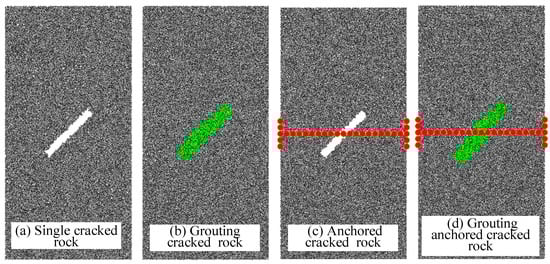
Figure 2.
Single-fractured rock.
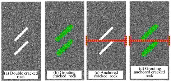
Figure 3.
Double-fractured rock.
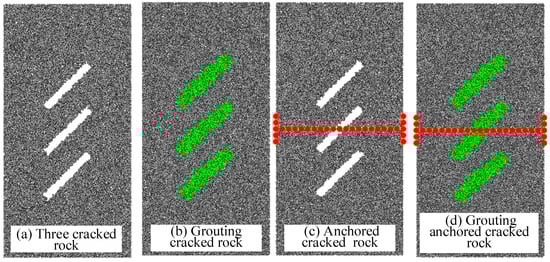
Figure 4.
Triple-fractured rock.
3. Experimental Results and Discussion
3.1. Mechanical Characteristics
Figure 5 is the stress–strain curve of fractured rock with different crack arrest measures. The greater the crack number, the lower the peak stress and the greater the peak strain of the fractured rock, the greater the peak stress and peak strain of the grouted rock. The greater the crack number, the lower the peak stress and the greater the peak strain of the anchored fractured rock. The greater the crack number, the greater the peak stress and the smaller the peak strain of the grouted anchored rock.
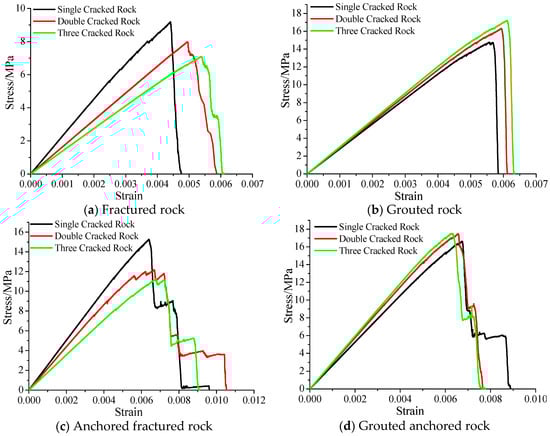
Figure 5.
Stress–strain curve.
Figure 6 is the variation curve of peak stress of the fractured rock with different crack arrest measures. The fracture reduces the peak stress of rock, the more the crack number, the greater the reduction of peak stress.
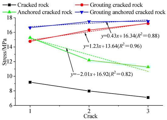
Figure 6.
Variation curve of peak stress.
When the crack numbers in the grouted rock are one, two, and three, the peak stresses are 14.76 MPa, 16.31 MPa, and 17.22 MPa, which are 5.58 MPa, 8.33 MPa, and 10.13 MPa higher than those of the fractured rock without crack arrest measures, respectively. The greater the crack number in the grouted rock, the greater the increase in peak stress. The main reason is that the peak stress of the grouting material is large, the greater the crack number, the greater the amount of grouting material used, the greater the effect of improving the strength of the fractured rock, so that the peak stress of the fractured rock with three cracks is high.
When the crack numbers in the anchored fractured rock are one, two, and three, the peak stresses are 15.27 MPa, 12.18 MPa, and 11.25 MPa, which are 6.09 MPa, 4.20 MPa, and 4.16 MPa higher than those of the fractured rock without crack arrest measures, respectively. The greater the crack number in the anchored fractured rock, the lower the increase in peak stress. The main reason is that the range of the effective reinforcement of the bolt is limited. When the crack number is 1, the bolt acting on the fractured rock can effectively prevent crack expansion and increase the peak stress of the fractured rock. When there are multiple cracks in the rock, some cracks are beyond the range of the effective reinforcement of the bolt, the bolt cannot effectively prevent the cracks from expanding so that the peak stress of the double-fractured rock is lower, the peak stress of the triple-fractured rock is the lowest.
When the crack numbers in the grouted anchored rock are one, two, and three, the peak stresses are 16.64 MPa, 17.48 MPa, and 17.51 MPa, which are 7.45 MPa, 9.50 MPa, and 10.41 MPa higher than those of the fractured rock without crack arrest measures, respectively. The greater the crack number in the grouted anchored rock, the greater the increase in peak stress. For fractured rocks with grouted anchored arrest measures, the peak stress of single-fractured rock is the smallest, and the difference between the peak stress of double-fractured rock and triple-fractured rock is small. It indicates that the effect of increasing peak stress of multi-fractured rock with the grouted anchored arrest measure is not obvious.
The peak stress of anchored single-fractured rock is greater than that of grouted single-fractured rock, and the peak stress of grouted anchored single-fractured rock is greater than that of anchored single-fractured rock. It shows that for improving the peak stress effect of single-fractured rock, grouted anchored arrest measure > anchored crack arrest measure > grouted arrest measure.
The peak stress of grouted multiple-fractured rock is greater than that of anchored multiple-fractured rocks, and the peak stress of grouted anchored multiple-fractured rock is greater than that of grouted multiple-fractured rocks. It is shows that for improving the peak stress effect of multiple fractured rocks, grouted anchored arrest measure > grouted arrest measure> anchored crack arrest measure.
The peak stress of the fractured rock with different crack arrest measures is fitted, and the fitting formula is as follows:
The grouted arrest measure,
y = 1.23x + 13.64 (R2 = 0.96)
The anchored crack arrest measure,
y = −2.01x + 16.92 (R2 = 0.82)
The grouted anchored arrest measure,
y = 0.43x + 16.34 (R2 = 0.88)
Figure 7 is the variation curve of the elastic modulus of the fractured rock with different crack arrest measures. The greater the crack number, the lower the elastic modulus of the anchored fractured rock, the greater the elastic modulus of the grouted rock and the grouted anchored rock. Filling the grouting material in the crack can change the rock properties and increases the elastic modulus of the fractured rock.
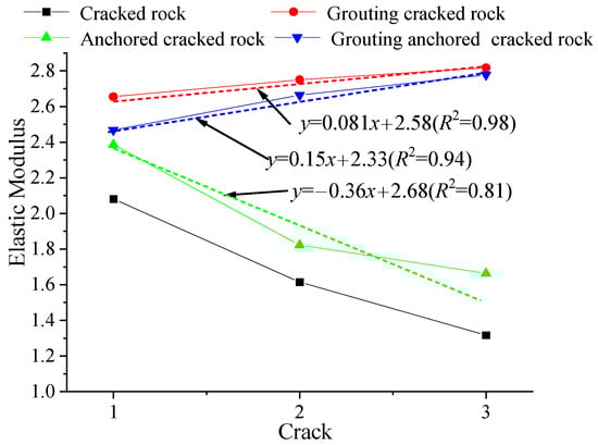
Figure 7.
Variation curve of elastic modulus.
When the crack number is constant, the elastic modulus of the grouted anchored rock is the largest, the elastic modulus of the grouted rock is second, and the anchored fractured rock is the smallest. It shows that the grouted anchored arrest measure can effectively improve the elastic modulus of the fractured rock.
The elastic modulus of the fractured rock with different crack arrest measures is fitted, and the fitting formula is as follows:
The grouted arrest measure,
y = 0.081x + 2.58 (R2 = 0.98)
The anchored crack arrest measure,
y = −0.36x + 2.68 (R2 = 0.81)
The grouted anchored arrest measure,
y = 0.15x + 2.33 (R2 = 0.94)
3.2. Fracture Propagation
Figure 8 is the variation curve of the crack number. The variation of the crack number can effectively reflect the fracture propagation of the fractured rock with different crack arrest measures. The cracks generated in the rock specimen grow in steps. The main reason is that fracture propagation is driven by energy. When the energy gathered at the crack tip meets the requirements of fracture propagation, the crack expands. At the initial stage of loading of coal–rock composite structure, the pores and cracks in the rock samples are gradually compacted, no cracks are produced in this process. With the increase of stress, the crack tip and the fragile part of the specimen first meet the fracture propagation conditions, and the cracks expand or produce small cracks, the cracks increase. With the development and expansion of small cracks, small cracks are gradually connected to form larger cracks, the cracks increase again. Large cracks continue to expand and develop, forming large macroscopic cracks, the phenomenon of specimen cracking, sidewall and spalling appears, the cracks increase sharply. As can be seen from the figure, the development and expansion of cracks can be divided into four stages.
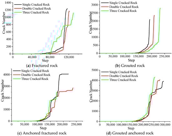
Figure 8.
Variation curve of the crack number.
In the first stage, the pores and cracks in the rock specimen are gradually compacted, and no new cracks are produced.
In the second stage, the stress is higher than the crack initiation stress, the micro-cracks in the rock specimen begin to develop, the crack number increases slowly.
In the third stage, the stress continued to increase, the cracks in the rock expanded rapidly, the crack number increased in steps, the large macro-cracks were generated inside the specimen.
In the fourth stage, the macro-cracks in the rock specimen are connected, the crack number increases rapidly in a straight line, and the rock specimen is destroyed at this stage.
Figure 9, Figure 10 and Figure 11 are the rose diagram of the direction of fracture propagation in the fractured rock under different crack arrest measures. The range of weak areas formed by different crack numbers in the fractured rock is different. The position and direction of crack expansion in the weak area are also different under the action of axial stress. The grouted arrest measure, the anchored crack arrest measure, and the grouted anchored arrest measure have different crack arresting mechanisms for the fractured rocks with different crack numbers, resulting in different fracture propagation directions and crack numbers in the fractured rocks with different crack arrest measures. It can be seen that the crack number is relatively large in the direction of 75–105°, indicating that the fracture propagation direction is mainly along the stress direction. The crack number generated in all directions of the fractured rock and the anchored fractured rock is smaller than that of the grouted rock and the grouted anchored rock. The greater the crack number, the greater the crack number generated in all directions in the grouted rock and the grouted anchored rock. It shows that the grouted arrest measure aggravated the crack number in each direction.
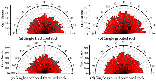
Figure 9.
Rose diagram of the fracture propagation direction of single-fractured rock.
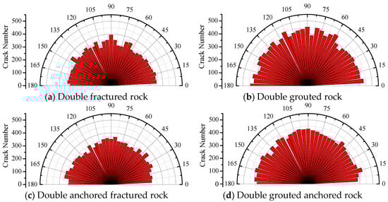
Figure 10.
Rose diagram of the fracture propagation direction of double-fractured rock.
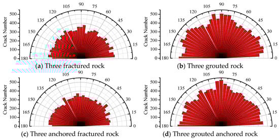
Figure 11.
Rose diagram of the fracture propagation direction of triple-fractured rock.
Figure 12 is the variation curve of the total crack number. The total crack number in the fractured rock with crack arrest measure is greater than that in the fractured rock without crack arrest measure. Because the crack arrest measures hinder crack expansion and development, the failure of the rock specimen needs more stress, the failure time of the rock specimen is prolonged, and the fracture has more time to develop. Thus, the total crack number of fractured rock specimens with crack arrest measures increases.
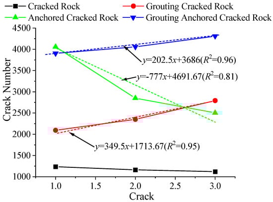
Figure 12.
Variation curve of total crack number.
The greater the crack number, the less the total crack number when the anchored fractured rock is damaged, and the greater the total crack number when the grouted rock and the grouted anchored rock are damaged.
The total crack numbers of single-grouted rock, double-grouted rock and triple-grouted rock are 2094, 2351, and 2793, which is 858, 1188, and 1673 more than the total crack number in the fractured rock without crack arrest measures, respectively. The total crack number of single-anchored fractured rock, double-anchored fractured rock, and triple-anchored fractured rock is 4058, 2851, and 2504, which is 2822, 1688, and 1384 more than the total crack number in the fractured rock without crack arrest measures, respectively. The total crack numbers of single-grouted anchored rock, double-grouted anchored rock and triple-grouted anchored rock are 3905, 4058 and 4310, which is 2669, 2895 and 3190 more than the total crack number in the fractured rock without crack arrest measures, respectively. The greater the crack number in the fractured rock, the greater the increase of the total crack number when the grouted rock and grouted anchored rock is damaged, the less the increase of the total crack number when the anchored fractured rock is damaged.
The total crack number of the fractured rock with different crack arrest measures is fitted, and the fitting formula is as follows:
The grouted arrest measure,
y = 349.5x + 1713.67 (R2 = 0.95)
The anchored crack arrest measure,
y = −777x + 4691.67 (R2 = 0.81)
The grouted anchored arrest measure,
y = 202.5x + 3686 (R2 = 0.96)
3.3. Failure Characteristics
Figure 13 shows the failure characteristics of fractured rocks with different crack arrest measures.
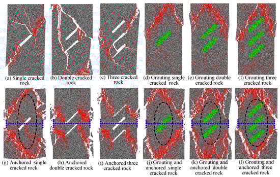
Figure 13.
Failure characteristics of fractured rocks with different crack arrest measures.
The anchored crack arrest measure forms a lateral constraint on the fractured rock, which prevents the development and expansion of cracks within the range of bolt reinforcement. However, a single anchor bolt only has a good anchoring effect on the fractures in the middle part of the fractured rock, and the fractures outside the anchoring range still develop and expand.
The grouted arrest measure fill the original cracks with grouting materials, improve the strength of the weak parts of the fractured rock, and increase the ability of the fractured rock to resist crack expansion. The more cracks, the greater the amount of grouting materials, the greater the strength of the fractured rock, and the stronger the ability to resist the crack expansion.
The grouted anchored arrest measure not only restrains the crack expansion, but also strengthens the weak parts of the fractured rock, effectively preventing the development and expansion of the crack.
The single-fractured rock specimen produces more cracks at both ends of the fracture and forms a wide crack zone. The crack zone extends to both sides along the original fracture to the edge of the specimen. The double-fractured rock specimens and triple-fractured rock specimens mainly produce large crack zones at the crack tip in the middle of the specimen.
There is no crack expansion at the crack tip of the grouted rock, but two intersecting crack zones are formed above the grouted, the angle between the two crack zones decreases gradually with the increase of the crack number. It indicates that the fractured rock with the grouted arrest measure can effectively prevent the fracture propagation at the original crack tip and change the crack propagation characteristics.
There is no crack expansion at the crack tip of the single-anchored fractured rock, the rhombic crack zone with a certain angle is formed above and below the original fracture. Because a certain range of anchoring area is formed around the crack and the bolt under the action of the bolt, which prevents the crack from expanding, especially the original crack tip. The double anchored fractured rocks produce a crack zone at the tip of the two original cracks, and the development direction of the crack zone is approximately perpendicular to the original crack. The triple-anchored fractured rocks produce a crack zone at the tip of the upper and lower original two original fractures, but there is no crack zone around the original fracture in the middle of the fractured rock. It indicates that the anchor belt has a certain anchoring effect on the intermediate original crack and effectively prevents crack expansion.
The grouted anchored rock produces diamond-shaped crack zones in the upper and lower parts of the original fracture, and no crack occurs at the tip of the original fracture. It indicates that the grouted anchored arrest measures form a certain range of anchoring area around the grouted and the bolt, the rock in the anchoring area has a higher ability to prevent the crack development.
3.4. Impact Energy Index
Impact tendency is an inherent property of rock, which can be expressed by impact energy index Ke. The impact energy index can be expressed by the ratio of pre-peak energy to post-peak energy in the process of rock uniaxial compression. The judgment basis of impact tendency is shown in Table 2.
Table 2.
The judgment basis of impact tendency.
3.4.1. Pre-Peak Energy and Post-Peak Energy
The pre-peak energy of fractured rocks with different crack arrest measures is calculated, the results are shown in Figure 14. The pre-peak energy of the fractured rock without crack arrest measure is the smallest, the pre-peak energy of the fractured rock with grouted anchored arrest measure is the largest. It shows that the grouted arrest measure and the anchored crack arrest measure are beneficial to the accumulation of pre-peak energy.
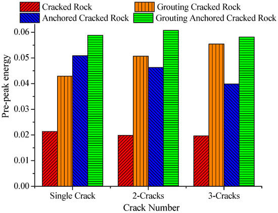
Figure 14.
Histogram of pre-peak energy.
When the crack number is one, the order of pre-peak energy of fractured rocks with different crack arrest measures is as follows, grouted arrest measure < anchored crack arrest measure < grouted anchored arrest measure. It shows that it is more advantageous to gather the pre-peak energy of a single fractured rock with a grouted anchored arrest measure. When the crack number is two or three, the pre-peak energy of fractured rocks with grouted anchored arrest measure is larger than that of fractured rocks with anchored crack arrest measure. Because the number of bolts used in multi-fractured rock is one, there is no effective crack arrest for more cracks. The grouted arrest measure of single fractured rocks is more beneficial to gathering the pre-peak energy.
Figure 15 is a histogram of post-peak energy of fractured rocks with different crack arrest measures. When the crack number is different, the post-peak energy of fractured rocks with anchored crack arrest measure is larger, indicating that the bolt can increase the post-peak energy of fractured rocks. With the increase of the crack number, the post-peak energy of the fractured rock without crack arrest measures gradually increased, and the post-peak energy of the fractured rock with a grouted arrest measure gradually decreased. Among them, when the crack number is two, the post-peak energy of the fractured rock with anchored crack arrest measure is the largest. When the crack number is two, the bolt can control the crack expansion and prolong the deformation of the fractured rock after the peak stress. When the crack number is three, the action range of the bolt can only prevent the central crack expansion, but cannot prevent the crack expansion of the upper and lower fractured rock.

Figure 15.
Histogram of post-peak energy.
3.4.2. Impact Energy Index
Figure 16 is a histogram of the impact energy index of fractured rocks with different crack arrest measures. The impact energy index of fractured rock without crack arrest measures decreases with the increase of the crack number. Because the stability of fractured rock with a higher crack number is poor, the capacity of bearing energy is smaller, and the impact energy index is smaller.
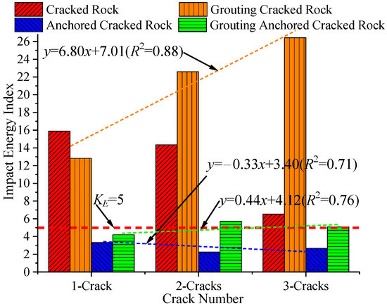
Figure 16.
Histogram of the impact energy index.
The impact energy index of fractured rock with grouted arrest measures increases with the increase of the crack number. Because the grouting material is filled into the crack, the mechanical properties of the fractured rock are changed. The more cracks there are, the more grouting materials are filled, and the larger the impact energy index is.
The impact energy index of the fractured rock without crack arrest measures and the fractured rock with grouted arrest measures are both greater than five, which has a strong impact tendency.
The impact energy index of the fractured rock with the anchored crack arrest measure and the grouted anchored arrest measure are significantly lower than that of the fractured rock without crack arrest measures. The anchored crack arrest measure makes the impact energy index of the fractured rock drop significantly, all of which are below five, and the impact energy index of the fractured rock is the minimum when the crack number is two. The impact energy of the fractured rock with anchored crack arrest measures and grouted anchored arrest measures is small. The post-peak energy of the anchored fractured rock is large, which makes the impact energy index of the anchored fractured rock small and reduces the impact risk.
The impact energy index of the fractured rock with different crack arrest measures is fitted, and the fitting formula is as follows:
The grouted arrest measure,
y = 6.80x + 7.01 (R2 = 0.88)
The anchored crack arrest measure,
y = −0.33x + 3.40 (R2 = 0.71)
The grouted anchored arrest measure,
y = 0.44x + 4.12 (R2 = 0.76)
4. Sensitivity Analysis
Sensitive factors can quantitatively analyze the sensitivity of influencing factors to target values [43,44]. This paper uses sensitivity factors to analyze the sensitivity of different crack arrest measures to the peak stress, elastic modulus, total crack number and impact energy index of fractured rock [45,46,47]. The expression of the sensitive factor is as follows,
where the Sxi is the sensitive factor, the g(x) is the relation function of parameter xi, the is the value when parameter xi takes the reference value .
Therefore, the sensitivity percentage γxi can be expressed as,
The larger the value , the more sensitive and dependent the indicator xi is on the parameter g(x). Hu et al. (2021) divided the design parameters into four levels according to the sensitivity percentage, important parameter, primary parameter, secondary parameter, and negligible parameter [44]. The sensitivity classification is shown in Table 3.
Table 3.
The sensitivity classification.
Based on the sensitivity analysis, the sensitivity percentages of grouted arrest measures, anchored crack arrest measures and grouted anchored arrest measures to the peak stress, elastic modulus, total crack number and impact energy index of fractured rock are calculated respectively. The results are shown in Figure 17.
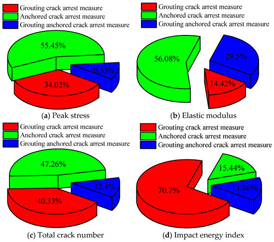
Figure 17.
Pie chart of the sensitive percentage.
The sensitivity percentages of peak stress of fractured rock with grouted arrest measures and anchored crack arrest measures are 38.56% and 37.83%, respectively, which are the primary parameters; the sensitivity percentage of grouted anchored arrest measures is 23.62%, which is a secondary parameter.
The sensitivity percentage of elastic modulus of fractured rock with grouted anchored arrest measures is 54.6%, which is the important parameter; the sensitivity percentage of anchored crack arrest measures is 32.17%, which is a primary parameter; the sensitivity percentage of grouted arrest measures is 13.23%, which is a secondary parameter.
The sensitivity percentages of total crack numbers of fractured rocks with grouted arrest measures, anchored crack arrest measures, and grouted anchored arrest measures are 42.50%, 31.14%, and 26.36%, respectively, which belong to the primary parameters.
The sensitivity percentages of the impact energy index of fractured rock with grouted arrest measures is 70.70%, which is an important parameter; the sensitive percentages of anchored crack arrest measures and grouted anchored arrest measures are 15.44% and 13.86% respectively, which belong to secondary parameters.
5. Conclusions
The greater the crack number, the greater the peak stress and peak strain of the grouted rock, the peak strain of the anchored fractured rock and the peak stress of the grouted anchored rock, and the smaller the peak stress of the anchored fractured rock and the peak strain of the grouted anchored rock. The effect of improving the peak stress of a single fractured rock is as follows, grouted anchored arrest measure > anchored crack arrest measure > grouted arrest measure. The effect of improving the peak stress of multi-fractured rock is as follows, grouted anchored arrest measure > grouted arrest measure> anchoring crack arrest measure.
With the increase of the crack number, the elastic modulus of fractured rock and anchored fractured rock decrease gradually, the elastic modulus of grouted rock and grouted anchored rock increase gradually. When the crack number is constant, the elastic modulus of grouted anchored rock is the largest, the elastic modulus of the grouted rock is the second, and the elastic modulus of the anchored fractured rock is the smallest.
The crack number generated in all directions of the fractured rock and the anchored fractured rock is smaller than that of the grouted rock and grouted anchored rock. The crack propagation direction is mainly along the stress direction. The original crack number is directly proportional to the total crack number when the grouted rock and anchored fractured rock breaks, and inversely proportional to the total crack number when anchored fractured rock breaks.
The pre-peak energy of single-anchored fractured rock and grouted rock is larger. The post-peak energy of the grouted rock decreases gradually with the increase of the crack number. The fractured rock and the grouted rock have a strong impact tendency. The anchored fractured rock and grouted anchored rock have a weak impact tendency.
Grouted arrest measures are important parameters for impact energy index, primary parameters for peak stress and total crack number, and secondary parameters for elastic modulus. Anchor crack arrest measures are the primary parameters for peak stress, elastic modulus and total crack number, and the secondary parameters for impact energy index. Grouted anchored arrest measures are important parameters for elastic modulus, primary parameters for total crack number, and secondary parameters for peak stress and impact energy index.
Author Contributions
S.L., project administration. F.X., data curation. T.L., software. B.Z., formal analysis. All authors have read and agreed to the published version of the manuscript.
Funding
This research was funded by Natural Science Foundation of Heilongjiang Province, grant number ZD2021E006.
Institutional Review Board Statement
Not applicable.
Informed Consent Statement
Not applicable.
Data Availability Statement
Not applicable.
Conflicts of Interest
The authors declare no conflict of interest.
References
- Ahmad, M.; Ahmed, N.; Khalid, P.; Badar, M.A.; Akram, S.; Hussain, M.; Anwar, M.A.; Mahmood, A.; Ali, S.; Rehman, A.U. Impact of pore fluid heterogeneities on angle-dependent reflectivity in poroelastic layers: A study driven by seismic petrophysics. Geomech. Eng. 2019, 17, 343–353. [Google Scholar] [CrossRef]
- Wang, J.; Ning, J.G.; Qiu, P.Q.; Yang, S.; Shang, H.F. Microseismic monitoring and its precursory parameter of hard roof collapse in longwall faces: A case study. Geomech. Eng. 2019, 17, 375–383. [Google Scholar] [CrossRef]
- Du, R.; Pei, X.; Jia, J.; Zhang, X.; Zhang, G. A novel observation method for determining the crack stress thresholds of rock based on Hooke’s law. Fatigue Fract. Eng. Mater. Struct. 2020, 43, 3050–3062. [Google Scholar] [CrossRef]
- Li, T.; Zhang, S.B.; Chen, G.B.; Qin, Z.C.; Li, Q.H. Study on energy dissipation and damage characteristic of coal-rock structural body under cyclic loading. J. Taiyuan Univ. Technol. 2022, 53, 649–659. [Google Scholar] [CrossRef]
- Xin, Z.H.; Moon, J.H.; Kim, L.S.; Kim, K.B.; Kim, Y.U. Effect of arbitrarily manipulated gap-graded granular particles on reinforcing foundation soil. Geomech. Eng. 2019, 17, 439–444. [Google Scholar] [CrossRef]
- Cao, K.; Khan, N.M.; Liu, W.; Hussain, S.; Liu, B.W. Prediction Model of Dilatancy Stress Based on Brittle Rock: A Case Study of Sandstone. Arab. J. Sci. Eng. 2020, 46, 2165–2176. [Google Scholar] [CrossRef]
- Wang, H.W.; Wu, Z.M.; Wang, Y.J.; Yu, R.C. Investigation on crack propagation perpendicular to mortar–rock interface: Experimental and numerical. Int. J. Fract. 2020, 226, 45–69. [Google Scholar] [CrossRef]
- Zhang, Z.S.; Wang, S.H.; Wang, C.G.; Wang, P.Y. A study on rock mass crack propagation and coalescence simulation based on improved numerical manifold method (NMM). Geomech. Geophys. Geo-Energy Geo-Resour. 2020, 7, 5. [Google Scholar] [CrossRef]
- Feng, H.; Zhang, X.M.; Zhou, X.S.; Ou, X.F. Experimental Study on the Compression Behavior of Grouted Rock with Bi-Directional Penetrating Crack. Appl. Sci. 2021, 11, 537. [Google Scholar] [CrossRef]
- Aliabadian, Z.; Zhao, G.F.; Russell, A.R. Failure, crack initiation and the tensile strength of transversely isotropic rock using the Brazilian test. Int. J. Rock Mech. Min. Sci. 2019, 122, 104073. [Google Scholar] [CrossRef]
- Spetz, A.; Denzer, R.; Tudisco, E.; Dahlblom, O. Phase-field fracture modelling of crack nucleation and propagation in porous rock. Int. J. Fract. 2020, 224, 31–46. [Google Scholar] [CrossRef]
- Taheri, A.; Zhang, Y.; Munoz, H. Performance of rock crack stress thresholds determination criteria and investigating strength and confining pressure effects. Constr. Build. Mater. 2020, 243, 118263. [Google Scholar] [CrossRef]
- Krykovskyi, O.; Krykovska, V.; Skipochka, S. Interaction of rock-bolt supports while weak rock reinforcing by means of injection rock bolts. Min. Miner. Depos. 2021, 15, 8–14. [Google Scholar] [CrossRef]
- Li, H.B.; Zhao, J.; Li, T.J. Micromechanical modelling of the mechanical properties of a granite under dynamic uniaxial compressive loads. Int. J. Rock Mech. Min. Sci. 2000, 37, 923–935. [Google Scholar] [CrossRef]
- Ghasemi, S.; Khamehchiyan, M.; Taheri, A.; Nikudel, M.R.; Zalooli, A. Crack Evolution in Damage Stress Thresholds in Different Minerals of Granite Rock. Rock Mech. Rock Eng. 2020, 53, 1163–1178. [Google Scholar] [CrossRef]
- Xiao, P.; Li, D.Y.; Zhao, G.Y.; Zhu, Q.Y.; Liu, H.X.; Zhang, C.S. Mechanical properties and failure behavior of rock with different flaw inclinations under coupled static and dynamic loads. J. Cent. South Univ. 2020, 2, 2945–2958. [Google Scholar] [CrossRef]
- Yan, Z.; Dai, F.; Liu, Y.; Du, H.B. Experimental investigations of the dynamic mechanical properties and fracturing behavior of cracked rocks under dynamic loading. Bull. Eng. Geol. Environ. 2020, 79, 5535–5552. [Google Scholar] [CrossRef]
- Jiang, Y.J.; Li, M.; Luan, H.J.; Shi, Y.C.; Zhang, S.H.; Yan, P.; Li, B.C. Discrete Element Simulation of the Macro-Meso Mechanical Behaviors of Gas-Hydrate-Bearing Sediments under Dynamic Loading. J. Mar. Sci. Eng. 2022, 10, 1042. [Google Scholar] [CrossRef]
- Xia, N.; Liang, R.Y.; Payer, J.; Patnaik, A. Probabilistic modelling of the bond deterioration of fully-grouted rock bolts subject to spatiotemporally stochastic corrosion. Struct. Infrastruct. Eng. 2013, 9, 1161–1176. [Google Scholar] [CrossRef]
- Makovetskiy, O.A. Application of Jet Grouting™ for Installation of Substructures of Estates. Procedia Eng. 2016, 150, 2228–2231. [Google Scholar] [CrossRef][Green Version]
- Shrivastava, N.; Zen, K.; Shukla, S.K. Modeling of Compaction Grouting Technique with Development of Cylindrical Cavity Expansion Problem in a Finite Medium. Int. J. Geosynth. Ground Eng. 2017, 40, 40. [Google Scholar] [CrossRef]
- Shrivastava, N.; Zen, K. Finite Element Modeling of Compaction Grouting on its Densification and Confining Aspects. Geotech. Geol. Eng. 2018, 36, 2365–2378. [Google Scholar] [CrossRef]
- Zhao, J.J.; Yan, H.Y.; Yang, C.X.; Bu, F.; Li, T. Laboratory research on anchorage effect of fractured rock mass under freezing and thawing. J. Eng. Geol. 2018, 26, 1257–1264. [Google Scholar] [CrossRef]
- Brown, D.R.; Warner, J. Compaction Grouting. ASCE Soil Mech. Found. Div. J. 1973, 99, 589–601. [Google Scholar] [CrossRef]
- Kelesh, A.M.; Mossaad, M.E.; Basha, I.M. Model of Compaction Grouting. J. Geotech. Geoenvironmental Eng. 2001, 127, 955–964. [Google Scholar] [CrossRef]
- Graf, E.D. Compaction Grouting Technique and Observations. ASCE J. Soil Mech. Found. 1969, 95, 1151–1158. [Google Scholar] [CrossRef]
- Stille, H.; Holmberg, M.; Nord, G. Support of weak rock with grouted bolts and shotcrete. Int. J. Rock Mech. Min. Sci. Geomech. Abstr. 1989, 26, 99–113. [Google Scholar] [CrossRef]
- Indraratna, B.; Kaiser, P.K. Analytical model for the design of grouted rock bolts. Int. J. Numer. Anal. Methods Geomech. 1990, 14, 227–251. [Google Scholar] [CrossRef]
- Li, S.C.; Zhang, W.J.; Zhang, Q.S.; Zhang, X.; Che, Z.Y. Research on advantage-fracture grouting mechanism and controlled grouting method in water-rich fault zone. Rock Soil Mech. 2014, 35, 9. [Google Scholar] [CrossRef]
- Li, C. Analytical models for rock bolts. Int. J. Rock Mech. Min. Sci. 1999, 36, 1013–1029. [Google Scholar] [CrossRef]
- Grasselli, G. 3D Behavior of bolted rock joints: Experimental and numerical study. Int. J. Rock Mech. Min. Sci. 2005, 42, 13–24. [Google Scholar] [CrossRef]
- Chen, L.; Tan, Y.L.; Zang, C.W. Test study of mechanical properties and failure characteristics of anchored rock. Rock Soil Mech. 2014, 2, 413–422. [Google Scholar] [CrossRef]
- Li, X.; Aziz, N.; Mirzaghorbanali, A. Behavior of fiber glass bolts, rock bolts and cable bolts in shear. Rock Mech. Rock Eng. 2016, 49, 2723–2735. [Google Scholar] [CrossRef]
- Wu, C.; Gong, F.; Luo, Y. A new quantitative method to identify the crack damage stress of rock using AE detection parameters. Bull. Eng. Geol. Environ. 2020, 80, 519–531. [Google Scholar] [CrossRef]
- Spang, K.; Egger, P. Action of fully-grouted bolts in jointed rock and factors of influence. Rock Mech. Rock Eng. 1990, 23, 201–229. [Google Scholar] [CrossRef]
- Liu, W.R.; Wang, X.; Li, C.M. Numerical Study of Damage Evolution Law of Coal Mine Roadway by Particle Flow Code (PFC) Model. Geotech. Geol. Eng. 2019, 37, 2883–2891. [Google Scholar] [CrossRef]
- Dehghan, M.; Mohammadi, V. The numerical simulation of the phase field crystal (PFC) and modified phase field crystal (MPFC) models via global and local meshless methods. Comput. Methods Appl. Mech. Eng. 2016, 298, 453–484. [Google Scholar] [CrossRef]
- Jiang, Y.J.; Zhang, S.H.; Luan, H.J.; Wang, C.S.; Wang, G.; Han, W. Numerical modelling of the performance of bolted rough joint subjected to shear load. Geomech. Geophys. Geo-Energy Geo-Resour. 2022, 8, 140. [Google Scholar] [CrossRef]
- Li, T.; Chen, G.B.; Li, Q.H. Experimental study on rock-coal-rock composite structure with different crack characteristics. Geomech. Eng. 2022, 29, 377–390. [Google Scholar] [CrossRef]
- Kim, A.R.; Cho, G.C.; Tran, A.T.P. Numerical modeling on the stability of slope with foundation during rainfall. Geomech. Eng. 2019, 17, 109–118. [Google Scholar] [CrossRef]
- Cheng, X.Z.; Luan, H.J.; Chen, L.J.; Jiang, Y.J.; Han, W. Numerical investigation on mechanical properties of inhomogeneous coal under uniaxial compression and the role of cleat distribution. Bull. Eng. Geol. Environ. 2021, 80, 7009–7027. [Google Scholar] [CrossRef]
- Skipochka, S.; Krukovskyi, O.; Palamarchuk, T.; Prokhorets, L. On the methodology for considering scale effect of rock strength. Min. Miner. Depos. 2020, 4, 2–30. [Google Scholar] [CrossRef]
- Filgueira, U.C.; Alejano, L.R.; Arzúa, J.; Ivars, D.M. Sensitivity Analysis of the Micro-Parameters Used in a PFC Analysis Towards the Mechanical Properties of Rocks. Procedia Eng. 2017, 191, 488–495. [Google Scholar] [CrossRef]
- Hu, Z.Q.; Ma, B.; Chen, X.Z.; Chen, L.L. Study on Sensitivity Parameters Analysis of Grouting Reinforcement Underpassing Existing Subway Tunnel by Numerical Modeling. Adv. Civ. Eng. 2021, 12, 1–13. [Google Scholar] [CrossRef]
- Wang, C.S.; Jiang, Y.J.; Wang, G.; Luan, H.J.; Zhang, Y.C.; Zhang, S.H. Experimental investigation on the shear behavior of the bolt-grout interface under CNL and CNS conditions considering realistic bolt profiles. Geomech. Geophys. Geo-Energy Geo-Resour. 2022, 8, 1–23. [Google Scholar] [CrossRef]
- Wang, C.S.; Liu, R.C.; Jiang, Y.J.; Wang, G.; Luan, H.J. Effect of shear-induced contact area and aperture variations on nonlinear flow behaviors in fractal rock fractures. J. Rock Mech. Geotech. Eng. 2022. [CrossRef]
- Chen, M.; Zang, C.W.; Ding, Z.W.; Zhou, G.L.; Jiang, B.Y.; Zhang, G.C.; Zhang, C.P. Effects of confining pressure on deformation failure behavior of jointed rock. J. Cent. South Univ. 2022, 29, 1−15. [Google Scholar] [CrossRef]
Publisher’s Note: MDPI stays neutral with regard to jurisdictional claims in published maps and institutional affiliations. |
© 2022 by the authors. Licensee MDPI, Basel, Switzerland. This article is an open access article distributed under the terms and conditions of the Creative Commons Attribution (CC BY) license (https://creativecommons.org/licenses/by/4.0/).