1. Introduction
Currently, distribution networks are prone to PQ issues such as interruptions, disturbances, flickering, sagging/swelling, harmonics, PF, and so on. This is due to a combination of inconsistent behaviors involving wind, the tides, the sun, and so on, as well as large nonlinear and unbalanced loads being used with electronic power equipment; however, increased usage of large nonlinear industrial loads leads to a decline in PF, and therefore, maintaining PQ has become the primary challenge for engineers who work in the power industry. Various configurations of single and three phase SUAPFs, using various control techniques, were suggested for three and four wire distribution systems, for balanced and unbalanced supply voltages, in order to attend to PQ issues. In addition, the most recent developments and applications of SUAPFs were also discussed [
1]. The novel controller, based on SRFT, was designed for the 3ⱷ-4 wire UPQC in order to effectively address the PQ issues for both the unbalanced and distorted loads of the distribution system [
2].
A hybrid controller with a combination of FLC and PIC properties was developed for SUAPFs with the aim of reducing THD so that it aligned with the standard. To show the superiority of the proposed controller, case study analysis was conducted for balanced and unbalanced loads [
3]. Moreover, a STF-based solar battery, which was connected to the SUAPF, was developed in order to efficiently regulate the reactive power and minimize the current harmonics. Additionally, the larger Kalman-type filter was used as a reference for the current assessment [
4]. Furthermore, the improved performance of artificial intelligence-based controllers such as FLC, ANNC, and so on, for use with SUAPFs, were able to address PQ problems effectively, even when dynamic load changes occurred [
5,
6,
7].
A solar integrated UPQC was developed, and its performance was tested on different load variations, using maximum power tracking, with the aim of diminishing THD and boosting the overall performance of UPQC [
8]. Moreover, the SRFT-based PIC was designed for the fuel cell that supported the SUAPF, with the goal of effectively suppressing the current harmonics and regulating voltage across the DC-link [
9]. A new controller, inspired by metaheuristic PSO and GWO-based algorithms, was suggested for the optimal tuning of the SUAPF, with the aim of managing the reactive power and minimizing the THD efficiently [
10]; however, to regulate the voltage, and to control the reactive power at the grid, a feed forward training-based ANNC was implemented on a wind/solar associated UPQC [
11].
A soccer league algorithm, based on the optimal tuning of a PI controller for a UPQC, was proposed to effectively address the PQ issues affecting the voltage and current [
12]. Moreover, a multilevel UPQC, which was associated with the PV/wind and fuel cell, was proposed with the aim of efficiently eliminating voltage distortions and current harmonics [
13]. The neuro-fuzzy-based hybrid controller was recommended for the UPQC in order to suppress the current harmonics and DC-link balancing in the distribution network for different loading conditions [
14]. The soccer league algorithm’s optimization-based load flow, which is suitable for both the transmission and distribution system, was formulated with the intention of minimizing the sum of the square of the active and reactive power mismatches for all of the buses [
15].
The STF-based SUAPF was designed to eliminate the requirement of LPF and PLL and to reduce THD; moreover, to prove its viability, an investigation was conducted to find out whether its practical performance could match its theoretical performance [
16]. The UPQC with a FL controller was suggested for non-linear R–L loads in order to suppress current harmonics, thereby reducing waveform imperfections. In addition, in order to gauge its superiority, analysis was undertaken on STF-based SUAPFs both with and without a UPQC [
17]. A Fourier transform was recommended for solar, wind, fuel-cell, and battery-connected UPQCs, with the aim of eliminating voltage distortions in the supply voltage and reducing imperfections in the load current [
18].
An adaptive, full order-based technique was suggested for the UPQC so that it could rapidly respond with a high accuracy for all dynamic load changes and grid conditions when faults were identified. Additionally, a BBO metaheuristic algorithm was used for optimally tuning the Kp/Ki of the PIC, with the goal of stabilizing the DC-link voltage oscillations [
19].
The UPQC was employed to eliminate the voltage imbalances and to reduce imperfections in current harmonics, in addition to improving how the network was utilized, by using an adaptive, neuro-fuzzy hybrid controller [
20]. A controller that used a hybrid of improved-bat and moth-flame algorithms was developed to deal with PQ issues, with the aim of reducing the power mismatch errors by appropriately tuning the Kp and Ki parameters [
21].
The FL controller was suggested for the series active power filter, for the grid connected to the distribution network, in order to attend to PQ problems such as voltage imperfections and current harmonics, and to maintain the DC-link capacitor voltage [
22].
The predator–prey-based firefly optimization technique was suggested for calculating the optimal Kp and Ki values of the PIC for the shunt active power filters, with the objective of minimizing THD and improving PF [
23]; however, conventional training algorithms, such as the back propagation (BP) and Levenberg–Marquardt (LM) algorithms, delivered solutions based on local optima. Hence, the neural network was trained by the lightning search algorithm (LSA), which was proposed with the aim of solving real time problems [
24]. The optimal tuning of PIC, based on the ant colony algorithm, was designed for the shunt active power filter, with the aim of minimizing THD under different loading conditions [
25]. A hybrid fuzzy back control scheme was proposed for the five-level UPQC, with the intention to minimize the THD and improve the PF [
26]. Ant–lion optimization-based training of feed forward ANNs was proposed to prevent solutions based on the local optima [
27]. In addition, training ANNs via back propagation (BP) has certain drawbacks in that it provides local, rather than global, minima. Grey wolf-based training of feed forward neural networks was proposed to solve real time problems [
28]. Moreover, an atom search optimization (ASO)-based UPQC was designed to solve PQ problems; this was achieved by integrating large renewable energy sources. In addition, a fractional order proportional integral derivative (FOPID) was introduced with ASO for solar-, wind-, and battery-integrated UPQCs, in order to effectively mitigate PQ issues [
29].
The main contributions of this paper are as follows. The S-ANNC was proposed for use with the SUAPF, and the FLC was proposed for use with the SEAPF of the UPQC that was associated with the SPV system and BS system. These proposals were based on the idea that the current THD would be minimized, thereby enhancing the PF, maintaining stable DC-link voltage during load/solar irradiation variations, and enabling compensation to occur during sagging/swelling and disturbances as the minimization of the MSE would be considered an objective function. In addition, the STF-UVGM generated SYP for both SEAPF and SUAPF instead of PLL; however, STF also eliminates the necessity of LPFs and HPFs when the FC and HC of the current are separated. The performance analysis of the proposed S-ANNC, which would be used with the FLC-based controller so that the UPQC could be used with SPV and BS (U-SPBS) systems, was carried out for five different test cases. A comparative study was also conducted to exhibit the supremacy of the S-ANNC over the GA, PSO, and GWO trained methods, and other methods that exist in the literature.
The remainder of the paper is organized as follows.
Section 2 details the construction of the proposed U-SPBS;
Section 3 details the proposed S-ANNC;
Section 4 presents the results and discussion; and
Section 5 concludes the paper.
3. Control Strategy of U-SPBS Using STF
When a fault or change in load occurs, the voltage across the capacitor of the DC-link varies; therefore, it is very important to ensure that the DC-link voltage is stable for a short period of time. In D-Q theory, currents and voltages are first transformed into a Clarke’s reference. In general, a conventional UPQC mechanism consists of a SUAPF, SEAPF, and PLL. Moreover, the purpose of a PLL is to separate the positively sequenced components from the supply voltage; however, in this proposed system, the STF-UVGM would be used to generate SYP, using the distorted supply voltages, so that it could perform the same role as HPFs and LPFs in terms of separating the FC and HC of currents. Ergo, the suggested system consists of a STF, SUAPF, and a SEAPF. The switching of the series and shunt VSCs occurs when the PWM voltage and PWM hysteresis current controllers are being used with the S-ANNC. The major parts of the proposed control structure are detailed below:
3.1. Design Procedure of the STF
The integral parts of the SRFT were designed by Hong-Sock, as shown in Equation (5).
where,
and
are the former and latter integral signals of the SRF. The transfer function
is shown in Equation (6), and it is found by implementing the Laplace transformation to Equation (6).
Ensuring that STF obtains a constant
value has already been established; thus,
is shown in Equation (7).
By exchanging
with
, and
with
, Equations (8) and (9) are obtained, as follows:
where,
is the required frequency, and
is the gain. If
decreases, the accuracy when obtaining the output decreases and vice-versa; therefore, by using a STF control, as shown in
Figure 3, distorted voltage/current signals can be obtained without any alteration to the magnitude or phase angle.
This section may be divided into subcategories. They should provide a concise and precise description of the experimental results, their interpretation, as well as any experimental conclusions that can be drawn.
3.2. STF-UVGM for the Proposed U-SPBS
The suggested STF-UVGM is a non-iterative method which can provide SYP from the supply voltage, as shown in
Figure 4 and
Figure 5. In Equation (10), the Clarke’s domain is used to transform the supply voltage from the
to the
domain.
The FC and HC are separated from the distorted grid voltages, as noted in Equation (11), by only considering the
domain.
Here,
indicates the FC, and
indicates the HC, in the
domain. The STF suppresses the HC in the distorted grid voltages and extracts the FC to produce SYP with high quality. The Laplace transformation of STF is expressed in Equation (12).
where,
is the chosen gain, with a value of 20, and
is the cut-off frequency, with a value is equal to the system’s frequency, at 50 Hz. The SYP’s
and
are generated from Equation (13) which omits PLL. STF-UVGM effectively generates SYP for distorted supply voltage of U-SPBS.
3.3. Shunt Controller
The main function of the SUAPF is to suppress the current harmonics by injecting the required amount of current and to regulate the DC capacitor in order to keep the voltage stable. The shunt controller adapts the (i)
-
,
-
,
-
, and
-
transformations; and (ii) S-ANNC is implemented to minimize the THD and regulate the DC-link voltage so that it remains stable. The proposed S-ANNC compares the actual voltage of the DC-link with the reference voltage, and it transfers the error (current output) into the axis. The controller of the S-ANNC is shown in
Figure 4. As the
-
,
-
,
-
, and
-
transformations are already available in the literature, the design of the S-ANNC is shown in
Figure 5.
Initially, in the SUAPF, the load currents are shifted to
coordinates by using the Clarke transformation. By performing the Laplace conversion, the STF splits the HC from the FC. As a result of the HC obtained from the
coordinates, and the SYP obtained from Equation (18), the HC in the d-frame is able to be obtained. The reference for the current generation and stable DC-link voltage plays a vital role in determining the performance of the SUAPF; however, if the load changes, the active power flow in the SUAPF may vary, which leads to voltage instability across the DC-link. To regulate the voltage across the DC-link, the active power in the SUAPF is made equal to the switching losses. The suggested S-ANNC injects an appropriate error current signal,
, which is obtained from the difference between the actual and reference DC-link voltages. The mathematical expression for the calculation of the DC-link voltage is shown in Equation (14).
The reference load current in the
d-axis can be calculated using Equation (15).
The reference load currents are transformed into an domain. Then, the reference shunt injected currents are transformed into an domain. The errors that the currents obtain from the comparison between the actual and reference signals are transferred to a hysteresis control in order to produce appropriate gating pulses.
3.3.1. Proposed S-ANNC
ANNs are featured among the more the famous artificial intelligence techniques. An ANN is a human-inspired mathematical model, and it is very adaptable in terms of its application to electronic power system controls. MLPs are familiar neural networks. The advantages of ANNs include its ability to self-learn, its fault tolerance, fast convergence, robustness, and so on. The architecture of an ANN consists of three layers, which are IL, HL, and OL. The most significant factor that affects the performance of an ANN is the learning algorithm that is selected for its training. Training is the process of searching for the best group of weights that links the neurons between the layers of the ANN to reduce error. Training methods for MLP networks mainly consist of two types: supervised and unsupervised. In general, these methods consist of two types, which are gradient search and meta-heuristic. BP is the most famous gradient-based conventional training method that is adopted for MLP networks. Even though the BP method is famous, it suffers from a few limitations: it provides a poor initial guess with regard to the weights, it has a slow convergence time, and its chances of getting trapped in local minima are high. Moreover, meta-heuristic algorithm-based search methods depend on the random selection of initial guesses during their optimization process. The benefit of using these methods is that they find the best global optimal solution rather than the local optimal solution; however, they do need prior information concerning the chosen problem, and their main limitation is the computational time. These algorithms can be applied for the weight, parameter, and architecture optimization of an ANN. The aim of supervised learning is to diminish the error between the desired and output values.
In MLP networks, neurons between the layers are interrelated via numerical weights, and each neuron consists of summation and activation functions. The purpose of a summation function is to sum up the product of inputs and weights, as well as bias, as shown in Equation (16), where
is the connection weight connecting
to neuron k,
is a bias term, and m is the total number of neuron inputs. Usually, a nonlinear activation function, such as a sigmoid function, is used; this is shown in Equation (17). Therefore, the output of neuron k can be described as per Equation (18).
In the proposed work, a single layer, feed-forward ANN is trained for DC-link balancing.
is compared with
, and its error is taken as the input data, whereas the desired output,
, is taken as the target data for the ANN.
Figure 5 shows the ANN structure for the DC-link with 100 neurons in the HL.
Figure 6 shows the architecture of the S-ANNC controller for the DC-link. It was proven in [
29] that a MLP network with a single hidden layer is adequate for the approximation of any function. The optimal selection of weights provides a much better performance than the selection of network architectures and activation functions. Overfitting is one major problem of neural networks, though it can be overcome by reducing the complexity of the network, ensuring that stopping early is used regularly, and so on. In this work, in order to reduce the complexity and number of parameters of the network, a single layer was used.
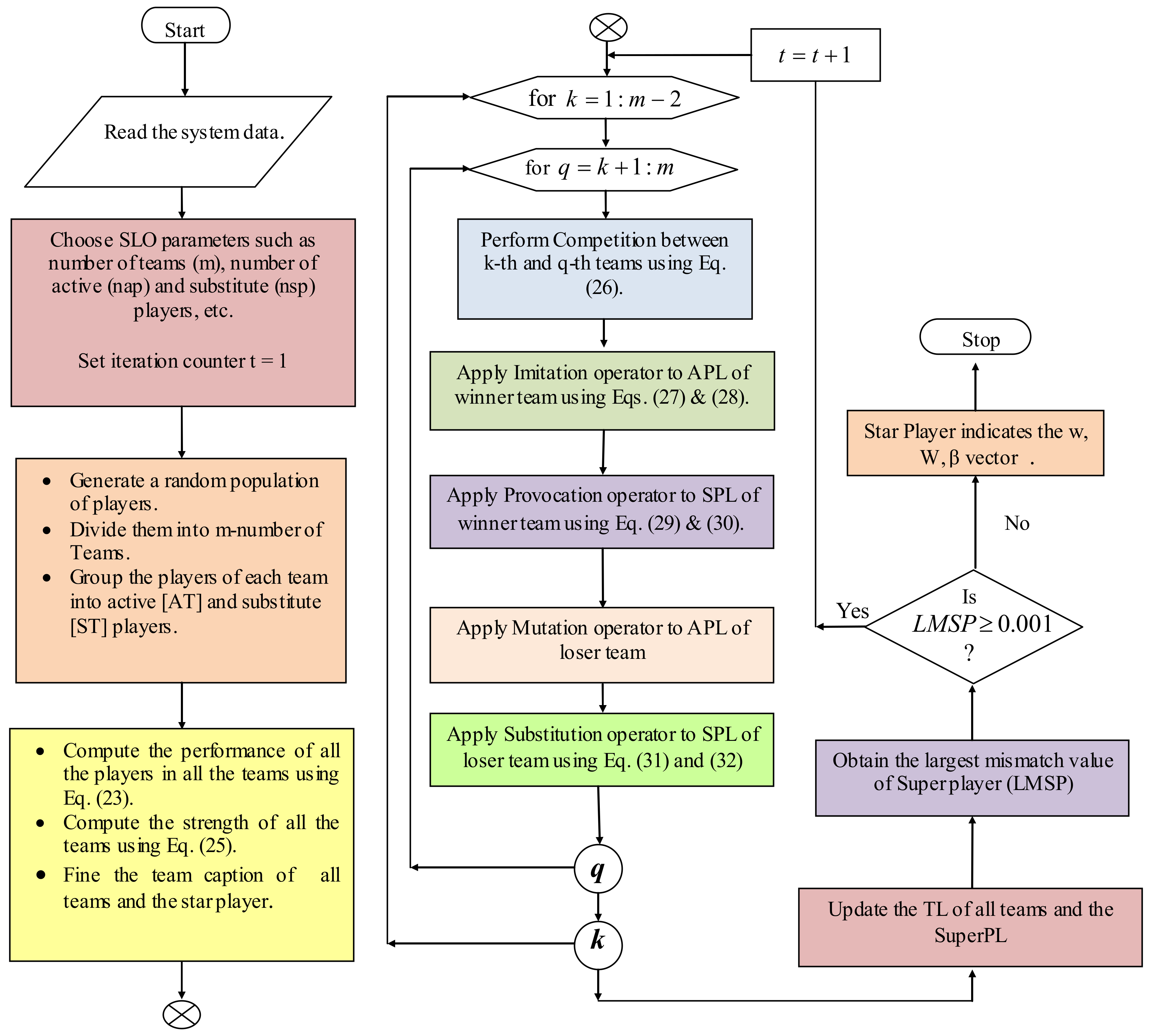
3.3.2. Soccer League Optimization (SLO)
SLO is a population-based sports algorithm that is derived from the competitive behavior within a team of players, and between other teams in the league. The performance of each player can be improved by competing with another player, thus improving the strength of the team. This paper provides an overview of a soccer league optimization-trained ANN.
The selection of weights can be treated as an optimization problem. Given that the aim is to minimize the value of the common mean squared error (MSE), the optimum parameters,
, are chosen, and the fitness function is formed. With this approach, each player (y) is treated as a selected design parameter (weights) that is represented in a vector form, as shown in Equation (19).
The constraints are represented as
where,
= number of design variables.
The total number of players is randomly produced and clustered into a certain number of teams. Each team consists of a set of active players (APLs), and substitute players (SPLs). In any team, each player has his/her own skills which are represented in Equation (21).
The total number of players (population) and their teams (T) are denoted as,
where,
is the jth APL of kth team.
is the jth SPL of kth team.
and denote the number of APLs and SPLs, respectively.
is the kth active team with nap.
is the kth substitute team with nsp.
denotes the total number of control variables.
denotes the number of teams.
In each team, the fitness of each player depends on his/her skills, which is calculated using a performance function (
) that is derived from the objective function (minimization of the
of the ANN), as shown below:
where the
is evaluated using Equation (24),
is the actual output,
indicates the predicted output, and
n is the total number of instances.
The likelihood of a team winning the league depends on the strength of the players. The strength of the kth team (
) can be calculated using Equation (25).
The player that has the best fitness value in each (kth) team is considered to be the team leader (
), and the best player among all team leaders, is called the super player (SuperPL) of the league. The probability of the kth team winning against the qth team is shown in Equation (26).
Once the match is completed, the players of winning team and losing team implement certain actions to enhance their performance. The mathematical representation of these actions may be shown as a series of operators, as detailed below.
Imitation operator: the APLs of the winning team try to imitate the TL and
SuperPL in order to enhance their own performance, as shown in Equations (27) and (28).
where,
,
,
, and
are random numbers.
If the performance of the APLs is improved, then the can perform large movements, in accordance with Equation (27). Alternatively, the player shifts towards medium movements, in accordance with Equation (28). If there is no improvement after the abovementioned actions have been taken, the player will remain in their previous position.
Provocation operator: The SPLs try to perform better than the APLs of the winning team. The SPLs move in accordance with the average direction of the APLs, using Equations (29) and (30).
where
, and
are random numbers.
is the mean direction of the APLs in the winning team.
is the jth substitute of kth team.
If the performance of the APLs is better than the old one, then the moves forward, in the average direction of APLs, using Equation (29). Alternatively, the player moves backwards, as per Equation (30). If there is no performance improvement after the abovementioned movements have been completed, he/she is replaced with a vector that has a random solution.
Mutation operator: The APLs of the losing team try to explore possible ways to enhance their performance. During this process, they randomly change their positions by adopting the mutation operator.
Substitution Operator: To escape from local traps, the losing team creates a fresh combination of substitutes (
j and
p) by integrating two of the existing members, as per Equations (31) and (32).
where,
is a random number. The chosen parameters of the soccer league algorithm are given in
Table 3. The flowchart of the proposed design method is shown in
Figure 7. An advantage of S-ANNC is its ability to quickly converge with fewer numbers of iterations that are used for both linear and nonlinear loads, and multi-objective problems.
3.4. Series Controller
The main purpose of the SEAPF is to eliminate voltage-related PQ issues by injecting an appropriate voltage through the interfacing transformer. As the source and load voltages transform from abc to
, and then to
, and as two such voltage transformations are already noted in the literature, the design of the FLC as a reference for voltage generation is discussed in this paper. The reference series injected a voltage that was obtained from the difference between the actual reference source and the load voltage. The injected series voltage passes through the PWM voltage controller in order to generate the required pulses for the SEAPF, as shown in
Figure 8.
FLC for Reference Voltage Generation
The FL is an intelligent controller which functions by using linguistic rules. The main components of an FL system are a fuzzifier, a rule base, knowledge base, an inference, and a defuzzifier. The fuzzifier converts numerical inputs into linguistic variables with the support of the MF. The knowledge base stores the updated information concerning all of the input–output relationships. Then, the inference determines the rule base and the MF of the fuzzifier. Lastly, the defuzzifier coverts the fuzzy variables into a crisp output. The flow of the FL is illustrated in
Figure 9. The Takagi–Sugeno method was considered for the proposed work, as it takes the E and CE as inputs for the system (where E is obtained from Equation (33)). The triangle MFs concerning the E, CE, and output are shown in
Figure 10,
Figure 11 and
Figure 12. The fuzzy variables are represented by a triangular MF, as shown in
Figure 10,
Figure 11 and
Figure 12. They include the HP, medium positive (MP), LP, Zero (ZO), HN, medium negative (MN), and LN. The load voltage values are considered to be in the range of these linguistic terms, with 49 sets of MFs, as shown in
Table 4.
4. Simulation and Results
To analyze the performance efficiency of the suggested controller of a U-SPBS, a 3ⱷ distribution system was selected. The U-SPBS and load specifications are shown in
Table 5. The proposed system’s model was created in MATLAB/Simulink version 2016, using the SPS toolbox, as shown in
Figure 13. The proposed algorithm was repeated 20 times, and the best output was represented as the optimal solution. Five test studies were considered in order to attest to the extraordinary performance of S-ANNC on the proposed U-SPBS, as shown in
Table 6. These studies included multiple combinations of balanced/unbalanced/non-liner loads, supply voltages, variable irradiation, and conditions such as swelling/sagging/disturbances, under constant irradiation conditions of 1000 W/m
2 and a temperature of 25 °C.
Figure 14 shows the convergence characteristics of the S-ANNC with those of the GA, PSO, and GWO trained controllers.
The supply voltage is balanced for case studies 1 to 3, and unbalanced for 4 and 5, respectively, with various combinations of swelling, sagging, and disturbance voltages, variable irradiation levels, and constant temperatures. In addition, the THD obtained for all of the case studies of the proposed S-ANNC is further compared with those GA, PSO, and GWO trained techniques, and with the methods that are available in the literature, as shown in
Table 7. The PF is calculated from the THD using Equation (34) for all considered case studies, as shown in
Figure 15.
Here, is the measured angle between the voltage and current, whereas represents the displacement factor.
The sag or swell in voltage (
) is calculated using Equation (35).
The voltage injected by the series compensator of the U-SPBS is shown in Equation (36).
The current injected by the shunt compensator is shown in Equation (37).
In case 1, the supply voltage was balanced, and it sagged by 30% during the interval 0.25–0.35 s, and it swelled by 30% during the period 0.40–0.50 s. In addition, a disturbance was also introduced between 0.7 and 0.8 s, as illustrated in
Figure 16a. The load current waveform was observed as being non-sinusoidal and balanced due to the nonlinear rectifier load, as presented in
Figure 16b; however, it is clear that the U-SPBS can effectively eliminate voltage-related and current-related PQ issues by injecting a suitable compensatory voltage and current. Such an improvement in terms of the shapes of waveforms were also seen in the THD and PF values; therefore, the current THD decreased from 27.87% to 2.40%, which is a smaller decrease than those of other methods, as shown in
Table 6, and the PF rose from 0.8536 to 0.9965 by injecting the required series voltages and shunt currents. In addition, the suggested controller provides a stable DC-link voltage, as shown in
Figure 16c.
In case 2, the supply voltage was balanced with voltage-related issues, as with case 1; this is shown in
Figure 17a. Here, the load current waveform was observed to be non-sinusoidal and unbalanced due to the non-linear balanced and unbalanced loads acting simultaneously, as presented in
Figure 17b. It is clearly visible from the waveforms that the U-SPBS was able to manage voltage-related PQ problems effectively, and reduce THD from 16.80% to 3.42%, thereby boosting the PF value from 0.8013 to 0.9896 by injecting suitable compensatory voltages and currents; however, as demonstrated in
Figure 17b, the suggested controller works efficiently in terms of maintaining a constant DC-link voltage, even when the load varies.
In case 3, the supply voltage was balanced using a combination of a 3ⱷ balanced rectifier load and an unbalanced and induction furnace load; these loads were simultaneously injected, and are shown in
Figure 18a. The load current was observed to be highly non-sinusoidal and balanced, as shown in
Figure 18b; however, the S-ANNC was able to successfully suppress the THD from 19.91% to 2.67%, improve the PF from 0.8587 to 0.9995, and balance the load voltage by injecting suitable appropriate currents and voltages into the network. In addition, it also stabilized the DC-link voltage after the introduction of the large non-linear load, as shown in
Figure 18c.
In case 4, the supply voltage and load were both unbalanced, as shown in
Figure 19a. The load current waveforms were observed to be sinusoidal, but unbalanced, as shown in
Figure 19b. The S-ANNC suppressed the harmonics in the current waveform and decreased the THD from 9.33% to 2.94%. The PF was boosted from 0.83872 to 0.9994.
Figure 19c shows its performance in terms of its ability to regulate the DC-link voltage when the load varies.
In case 5, the unbalanced supply voltage was considered using a combination of 3ⱷ rectifier and induction furnace loads, as shown in
Figure 20a. The load current was balanced with a non-sinusoidal structure, as shown in
Figure 20b. The suggested S-ANNC effectively diminished the THD level, from 21.89% to 3.43%, and boosted the PF from 0.7925 to 0.9889; however, the stability of the DC-link voltage was maintained, as shown in
Figure 21, during the dynamic variation in solar irradiation, under constant temperature and load conditions.
In
Figure 14, it can clearly be seen that the proposed controller converges to allow for a lower MSE, in a smaller number of iterations, when compared to other techniques.
Table 8 provides a comparison of MSEs, examining the proposed method with those used in other techniques.
Figure 21 also proves that the proposed controller can provide a constant DC-link voltage when irradiation levels vary under constant temperature conditions. The proof of accuracy for the proposed S-ANNC with a regression plot is shown in
Figure 22. The THD spectrum for all test cases is shown in
Figure 23.
5. Conclusions
The hybrid controller, which used a combination of FLC and optimally trained ANN properties, was proposed in this paper for use in a U-SPBS. The design of the controllers for the SPV and BS were also specified, in addition to the development of S-ANNC for SUAPF, and FLC for SEAPF. This was done with the aim of:
Attaining rapid action when stabilizing the DC-link capacitance voltage, with the intention of achieving a minimum settling time.
Eliminating swelling, sagging, and disturbances in the supply voltage.
Suppressing the harmonics in the source current and boosting the PF by aiming to minimize the MSE.
From the investigation of the five test cases, it is clear that the proposed method was able to reduce the THDs to 2.40%, 3.42%, 2.67%, 2.94%, and 3.43% for the five test cases, and the PF was also reduced to a similar level. Moreover, in accordance with the comparative analysis, it has been proven that the performance of the proposed controller was much better than the GA, PSO, and GWO controllers. It also effectively maintains a stable voltage across the DC-link when load and solar irradiation varies. The proposed system can be studied further in a future study, using a multi-level UPQC with a micro-grid in the distribution network.


 ,
, 


