Article

Study on the Effect of Pile Foundation Reinforcement of Embankment on Slope of Soft Soil

1
Henan JiaoYuan Engineering Technology Group Co., Ltd., Zhengzhou 450001, China
2
Henan Zhongtu Construction Engineering Co., Ltd., Zhumadian 463000, China
3
Henan Transport Investment Group Co., Ltd., Zhengzhou 450016, China
*
Author to whom correspondence should be addressed.
Sustainability 2022, 14(21), 14359; https://doi.org/10.3390/su142114359
Submission received: 12 September 2022 / Revised: 12 October 2022 / Accepted: 12 October 2022 / Published: 2 November 2022
(This article belongs to the Special Issue Civil and Hydraulic Engineering Safety)

Abstract

:
In order to study the working mechanisms of pile foundations applied to embankment engineering on weak slope foundations, a finite element model of embankment on weak slope foundation reinforced by a pile foundation is established. The influence of the position and the length of the pile foundation on the stability of the embankment is studied, and the mechanical response of the pile foundations are also studied. The results show that the different positions of the pile foundation have great influence on the safety factor and deformation of the embankment. The safety factor varies greatly from one reinforcement location to another. The maximum vertical deformation of the embankment reinforced by the 3 m pile is 27 times that of the 7 m. With different pile lengths, the horizontal displacement of the pile foundation can be significantly reduced by approximately 83.3% at most. The research results may provide more scientific help for the design of embankments on soft soil slopes reinforced by pile foundations.

1. Introduction

With the development of the social economy, highways and railways will be built in many mountainous areas [1,2]. These areas will encounter many embankments filled with soft clay slopes, which cannot be regarded as a simple combination of slope foundation and soft soil subgrade, and the problem of building embankments on soft soils on slopes will be inevitable. Sloping soft ground is characterized by the sloping surface of the foundation or the bottom of the soft layer. The foundation soil is loose and has low strength and high compressibility [3,4,5], which can cause certain difficulties for slope stability, embankment filling and construction, cutting excavation, etc. [6,7,8] Moreso, under the influence of the slope, soft soil layer, embankment self-weight, and vehicle load, engineering problems such as uneven settlement, excessive lateral deformation, and side slope instability are prone to occur when constructing high-speed railroads on sloping soft ground [9]. Therefore, some measures are needed to strengthen the slope. Engineering practices at home and abroad show that the pile foundation has wide application and can be flexibly adopted with other prevention measures, which has obvious advantages in slope reinforcement engineering [10,11,12,13]. Therefore, pile foundation is often adopted in engineering to meet the requirements of embankment stability [14,15,16].
Many researchers have had significant achievements in this field. For example, A series of centrifuge model tests were conducted on the pile-reinforced slopes and corresponding unreinforced slopes under self-weight and vertical loading conditions according to Zhang et al. [17]. A three-dimensional multi-row polyurethane polymer micro anti-slide piles model for slope reinforcement that considers different embedded depth and pile location is established according to Wang and Han [18]. Scouring on pile groups embedded in soft clay is studied when piles are laterally loaded and affected by the formation of scour holes according to Wang and Zhou [19]. Tang and Yang focus on investigating the lateral behavior of a particular type of two-pile group foundations embedded in steep and weathered rock slopes [20]. The effect of the soil slope, undrained cohesion, pile-soil interface adhesion, pile diameter, and pile cap on the lateral load carrying capacity of pile located at the crest of the clay slope is studied using PLAXIS-3D according to Chandaluri and Sawant [21]. The problem of the optimal location of piles used to stabilize slopes is analyzed according to Li et al. [22]. However, there is little research about the stability of embankment on the slope soft soil reinforced by pile foundation [23]. In order to meet the specification requirements of engineering, it is necessary to study the stability of slope soft soil embankment and the effect of pile foundation reinforcement, which has important practical significance for the construction and development of high-speed railways and highways.
The finite element analysis method has the advantages of simple calculation and wide application range, and the strength reduction method is widely adopted to calculate the safety factor of the slope [24,25]. Therefore, finite element analysis method combined with the strength reduction method is adopted to study the embankment on soft soil slope reinforced by pile foundation in this paper. In this study, a pile embankment model is established by the finite element analysis method. The influence of the position and the length of the pile foundation on the stability of the embankment is studied. The influence of different reinforcement schemes on the stability of the slope soft soil embankment and the mechanical response of the pile foundation are studied, and the optimal reinforcement scheme for the slope soft embankment is proposed. The results of this study are of guiding significance to the design of embankments on soft soil slopes reinforced by pile foundations.

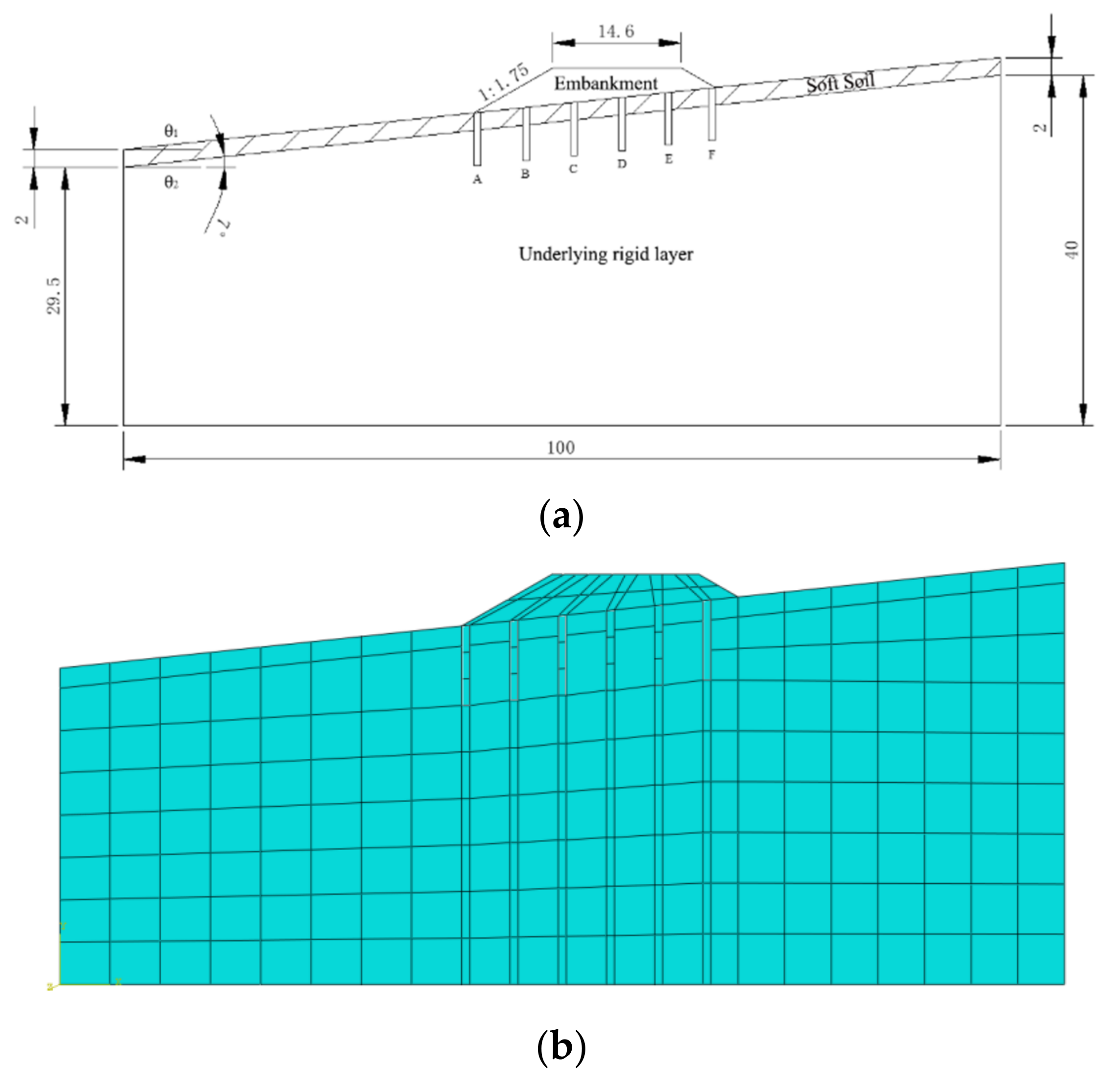
2. Establishment of Numerical Model of Embankment on Slope of Soft Soil

Based on a typical slope soft soil embankment project, a pile embankment model is established by using Abaqus. In order to reduce the influence of the boundary effect of the model on the finite element analysis, the length of the model is 100 m. In addition, the slope of the embankment is 1:1.75, the thickness of the soft soil layer is 2 m, and the slope is θ1 = θ2 = 7°. The model is composed of embankment filler, soft soil layer, and an underlying rigid layer. The left and right sides of the model are constrained in a horizontal direction, the bottom is constrained in horizontal and vertical directions, and the embankment and slope surface are free. The contact between the soil and the pile is hard contact. A planar strain quadrilateral element is adopted to mesh the Finite element model. In this paper, only the influence of soil self-weight is considered and other factors such as earthquakes, rainfall, and snow are not considered. The safety factor of the numerical model is calculated by finite element analysis combined with the strength reduction method. The pile foundation is reinforced at points A, B, C, D, E, and F, as shown in Figure 1a. The interval between the two points is 4 m, the pile diameter is 0.8 m, and the elastic modulus of the pile foundation is 30 Gpa. The Mohr–Coulomb constitutive is adopted for the embankment filling layer and the soft soil layer, which can stimulate mechanical properties of the soil, and the elastic constitutive model is adopted for the underlying rigid layer and the pile foundation. The material parameters are shown in Table 1.

3. Analysis of Influencing Factors

In this section, the influence of the position and the length of the pile foundation on the stability of the embankment is studied and the mechanical response of the pile foundation is studied. The study mainly includes the vertical deformation and safety factor of embankment, as well as shear stress and horizontal displacement of the pile foundation. Additionally, the embankment deformation refers to the deformation value without considering the direction, while the vertical deformation refers to the displacement of the numerical model in the vertical direction.

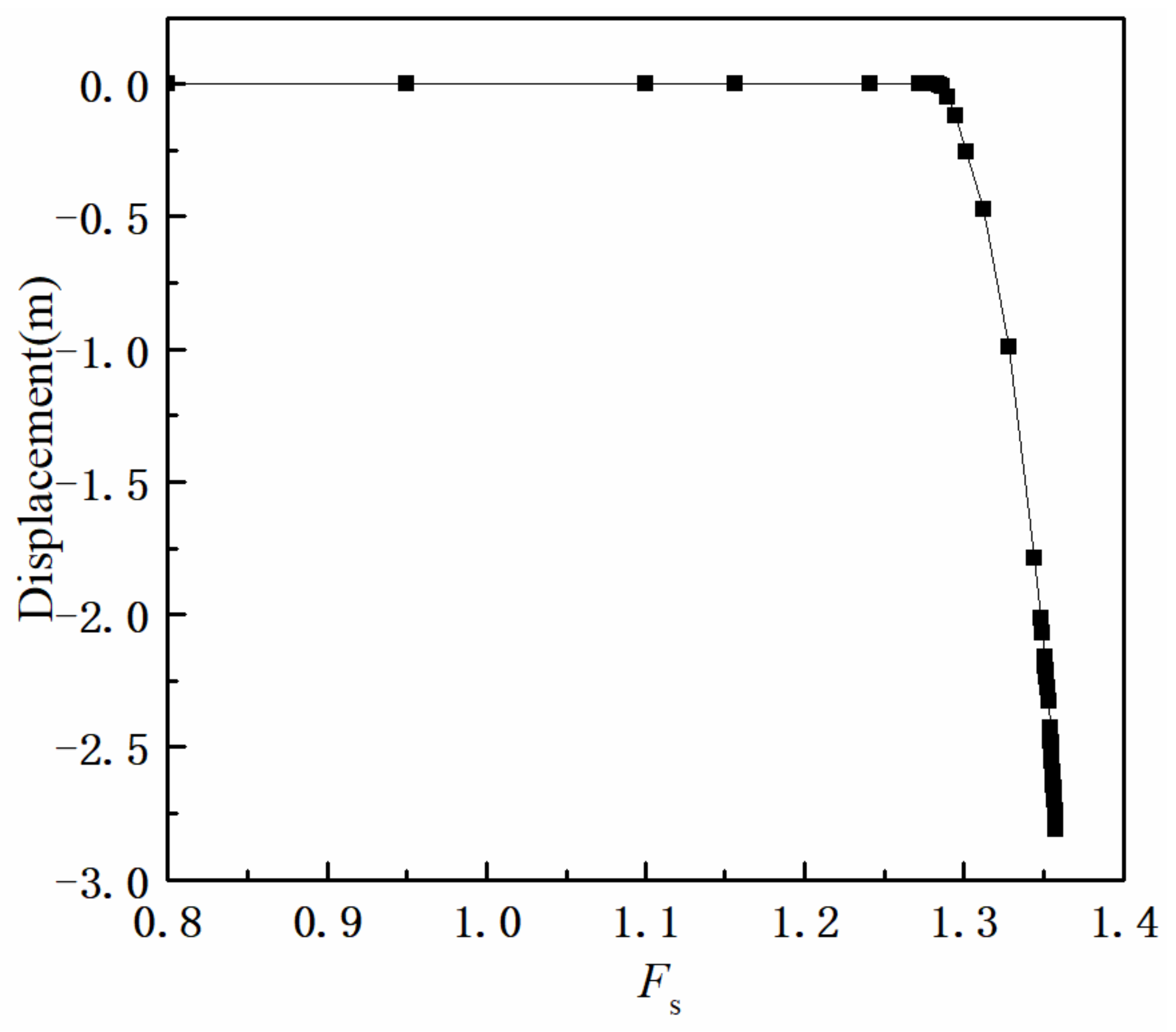
3.1. Strength Reduction Method

The strength reduction method is used to analyze slope stability by gradually reducing the strength index of the slope until the slope reaches the ultimate equilibrium state, and the reduction factor is the safety factor of the slope. For the Moore–Coulomb constitutive model, the yielding criterion is τ = c + σtanφ. When using the finite element strength reduction method, it is necessary to divide the values of c and tanφ by the strength reduction factor Fs to obtain a new set of strength parameters, cm and φm, to then carry out the finite element analysis and calculate repeatedly by Equations (1) and (2) until the soil reaches the critical damage state. The reduction factor corresponding to the critical state is the safety factor of the slope, as shown in Figure 2.
c m = c F s
φ m = a r c t a n t a n φ F s
where Fs is the strength reduction factor, c is the cohesion of the soil, and φ is the internal friction angle of the soil.
The strength reduction method can be implemented within the ABAQUS by setting the material parameters to vary with the field variables. The size of the initial value of the field variable is specified at the beginning of the analysis. The model calculation does not converge after several iterations, and the safety factor is read according to the evaluation criteria of the corresponding stability analysis.

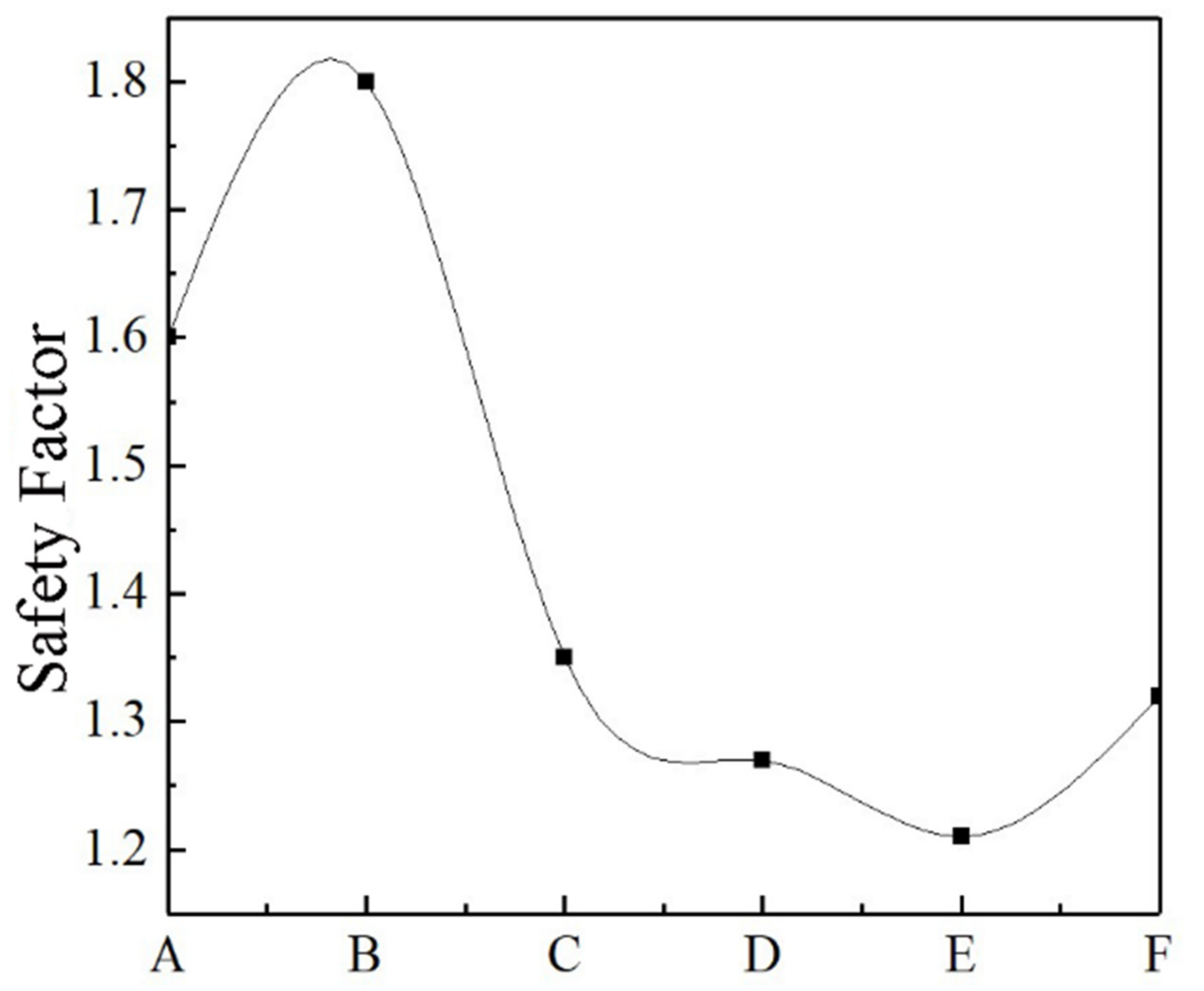
3.2. Influence of Pile Foundation Reinforcement Position

In order to study the influence of the reinforcement position of the pile foundation on the embankment on soft soil slopes, five models are established and the pile foundation is reinforced only for A, B, C, D, or E, respectively. The distance between the adjacent piles is defined as K among A, B, C, D, E, and F. The K is 4 m in this section, the pile diameter is 0.8 m, and the pile length is 6 m among the five models. First, the influence of the reinforcement position on the safety factor on the embankment is analyzed. The safety factors of different reinforcement positions are studied, as shown in Figure 3. The safety factor increases first and then decreases when the reinforcement position is changed from A to B. When the reinforcement positions are A or B, the safety factor is higher, which means that the points reinforced by the pile foundation can better improve the stability of the slope. When the reinforcement position is B, the safety factor is 50% higher than that of position E.
The influence of the different reinforcement positions on the vertical deformation of the embankment surface is studied. In Figure 4, x is the distance from any point on the embankment surface to the left end of the embankment surface. As shown in the Figure 4, the deformation of the embankment gradually decreases from the left side to the right side of the embankment surface, and the deformation is mainly concentrated on the left side of the embankment surface. Moreover, the different reinforcement positions have a great influence on the deformation of the embankment surface. For example, when the position E is reinforced with pile foundation, the embankment deformation is 25 m larger than the position A reinforced with pile foundation. As shown in Figure 4a, if the position A or B is reinforced, the deformation of the embankment can be better obviously controlled when compared with other positions. The difference in embankment surface vertical deformation for the model is analyzed in detail when the position A or B is reinforced individually, as shown in Figure 4b. If the position A is reinforced with the pile foundation, the vertical deformation of the embankment surface can be reduced more effectively than that of position B.
From the analysis mentioned above, when the lower left part of the embankment (position A to position C) is reinforced with pile foundation, the stability of the embankment can be better improved by the pile foundation than in other positions.
The mechanical response of the pile foundation at different positions is studied individually. The shear stress of the pile foundation at the respective reinforcement positions is shown in Figure 5, and the shear stress is mainly concentrated in the pile shaft from −1 m to −4 m, thus the pile foundation is more vulnerable to be damaged in this area. For models reinforced at different positions, when locations (B, C, D, E, F) are reinforced respectively, the average shear stress of the pile foundation decreases from the model reinforced at position B to the model reinforced at position F, which is consistent with the previous analysis. Although the pile foundation bears a small shear stress in the numerical model reinforced with pile foundation at position A, the stability of the embankment can be better improved.

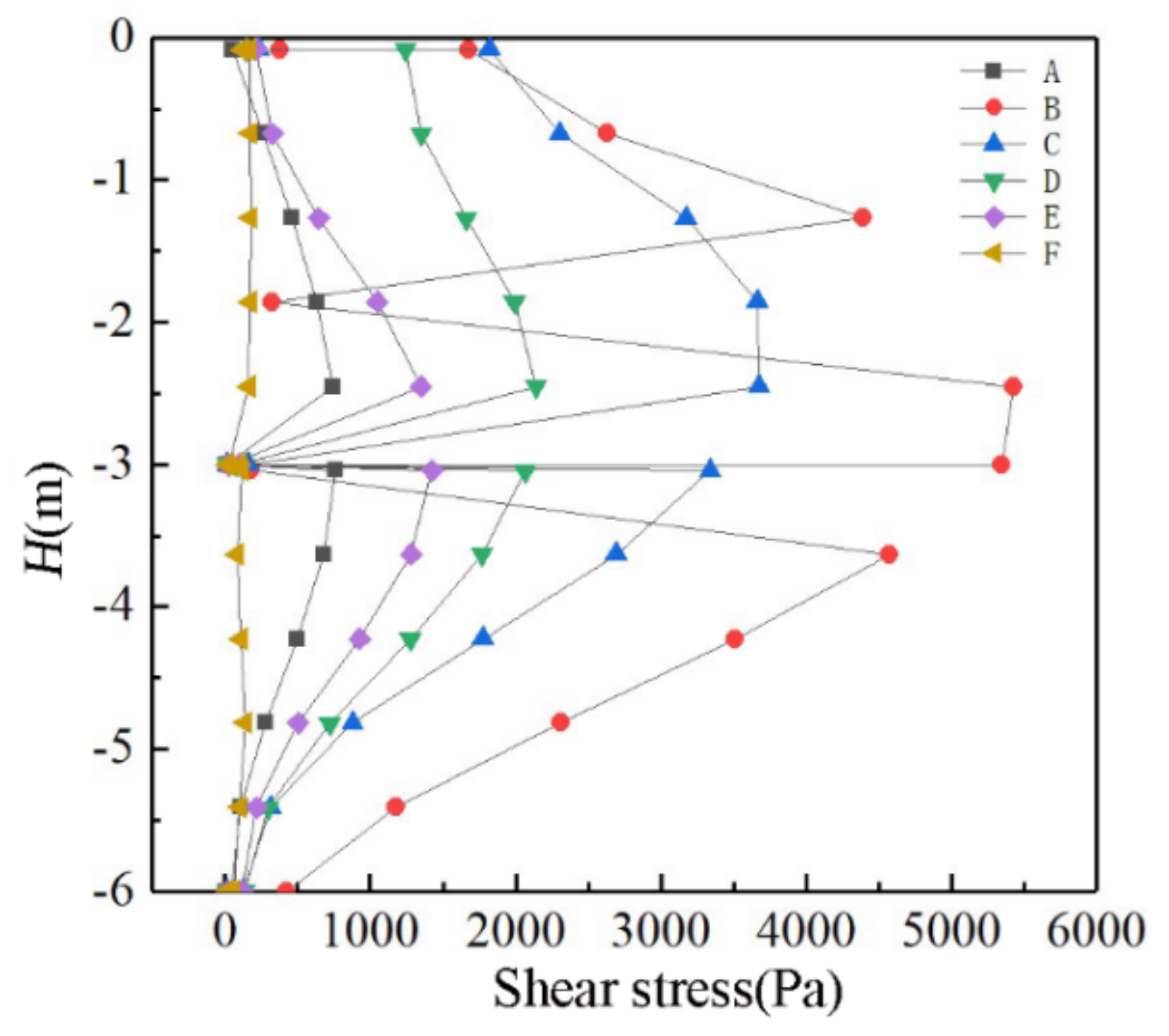
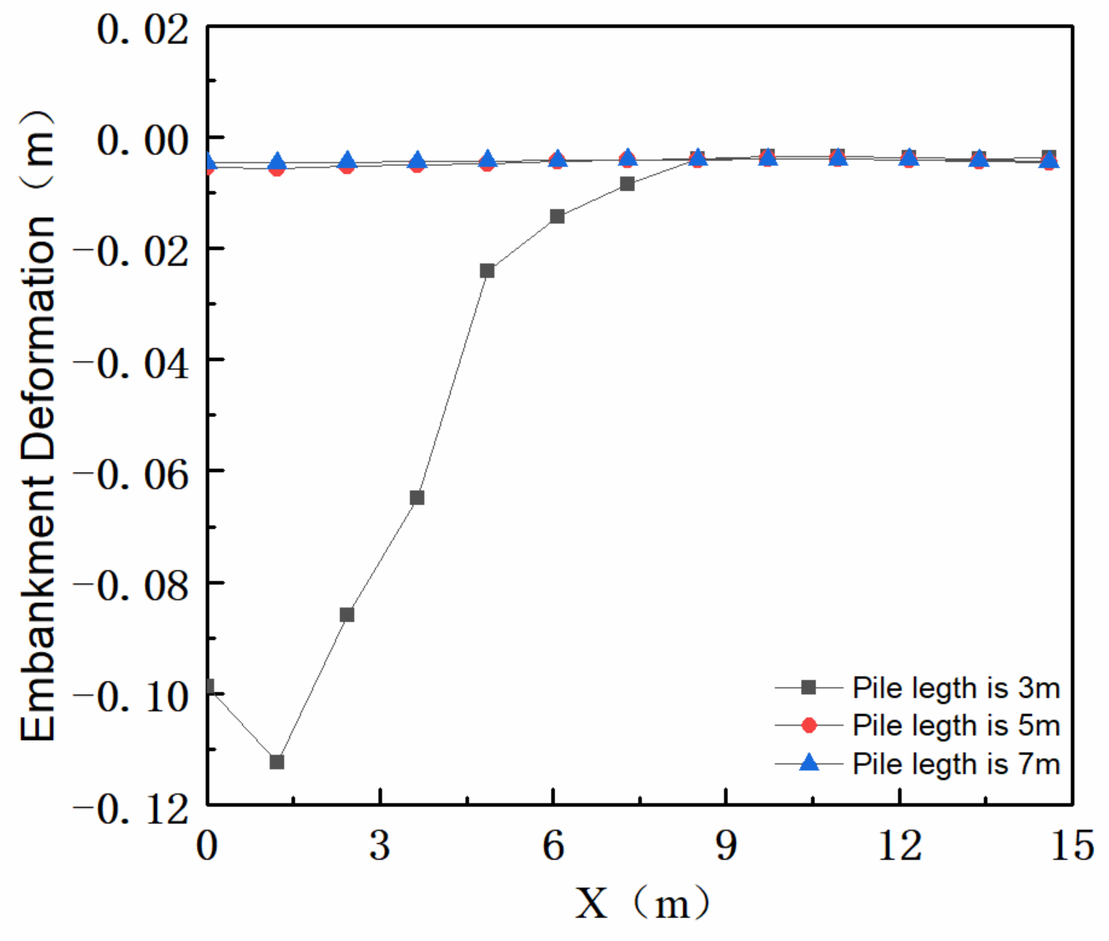
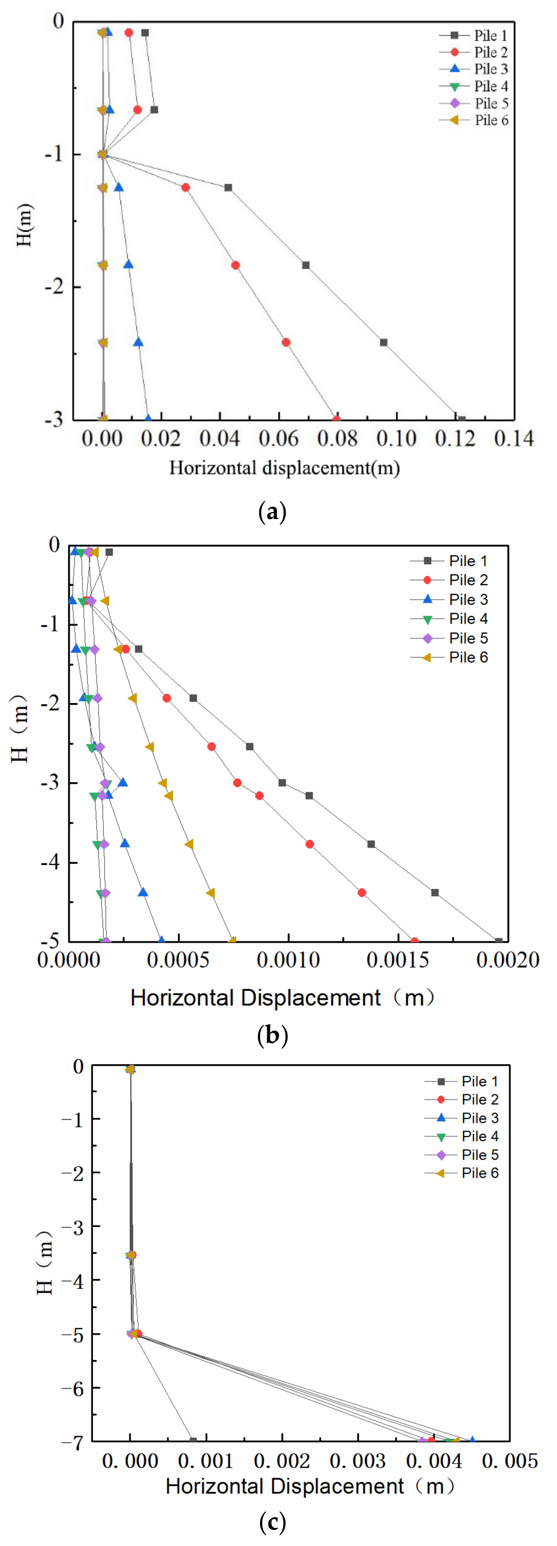
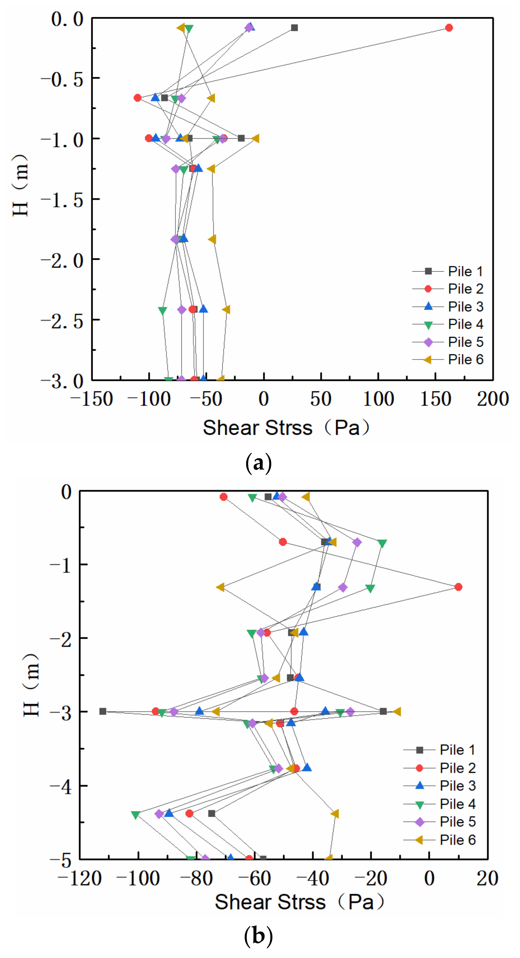
3.3. Influence of Pile Foundation Length

The mechanical parameters of the numerical model are shown in Table 1, and the K (the average distance between the adjacent piles) is 4 m, θ1 and θ2 are 7°. In order to analyze the influence of the length of the pile foundation on the safety factor, the embankment deformation of the embankment, and mechanical response of pile foundation, the positions A, B, C, D, E, and F are reinforced by six identical pile foundations and these pile foundations are recorded as pile 1, pile 2, pile 3, pile 4, pile 5, and pile 6 from left to right. Only the pile length of the finite element model is changed. The influence on the slope safety factor, embankment surface deformation, and the mechanical response of the pile foundation when the pile length L is 3 m, 5 m, or 7 m is analyzed. The results of the safety factor are shown in Table 2. When the number of pile foundations is 6, the length of the pile foundation has little influence on the safety factor, and the embankment on the soft soil slope remains relatively stable.
In a numerical model where points A, B, C, D, E, and F are reinforced by six identical pile foundations, the pile foundations are marked as pile 1, pile 2, pile 3, pile 4, pile 5, and pile 6 from left to right. In this finite element model, different lengths of the pile foundation are analyzed for the influence of reinforcement on the slope safety factor, embankment surface deformation, and mechanical response of pile foundation when the pile length L is 3 m, 5 m, or 7 m. The results of the safety factor are shown in Table 2. When the number of pile foundations is 6, the analysis results show that the influence of the pile foundation length on the safety factor is not significant.
The influence of different lengths of the pile foundation on the embankment surface deformation is shown in Figure 6. From Figure 6, when the pile length is 5 m and 7 m, the deformation of the embankment surface is around 4 mm, which indicates that when the pile length is 5 m and 7 m, not only can the requirements of the safety factor be met, but the vertical deformation of the embankment surface can also be well controlled.
When the pile length is 3 m, although the safety factor of the embankment meets the specification requirements of the project, the deformation of the embankment is relatively large and the maximum deformation can be 112 mm. The deformation is mainly concentrated in the left side of the embankment, which is 27 times that of the vertical deformation of the embankment when the pile length is 5 m and 7 m. Such a deformation has a great impact on the engineering of the embankment. Therefore, when the embankment is reinforced by the pile foundation, the appropriate pile length should be selected to control the embankment vertical deformation. Suitable pile length can control embankment deformation well.
The mechanical responses of pile foundations with different reinforcement depths are studied. Figure 7 shows the horizontal displacement of different lengths of pile foundations. As shown in Figure 7, the horizontal displacement of the pile foundation is greatly influenced by the pile length, and the horizontal displacement is mainly concentrated in the lower part of the pile. When the length of the pile foundation is increased from 3 m to 5 m, the displacement at the bottom of the pile foundation is significantly reduced. For example, for pile 1, the displacement at the bottom of the pile foundation is reduced by about 83.3%. When the length of the pile foundation increases from 5 m to 7 m, the horizontal displacement of the pile foundation is mainly concentrated at the bottom of all pile foundations and increases. The horizontal displacement of the bottom of each pile foundation tends to be consistent.
Based on the analysis mentioned above, the results show that increasing the pile group length can reduce the horizontal displacement of each pile foundation, but when the pile group length exceeds a certain range, the horizontal displacement of the pile foundation will not be reduced even with the increase of pile length. Therefore, when embankment on soft soil slope is reinforced with the pile foundation, it is necessary to select the appropriate pile length, which can not only make full use of the pile foundation, but also save the cost.
In order to better provide theoretical guidance on the design of engineering pile foundations, the mechanical respond of pile foundations is further analyzed. Figure 8a shows the shear stress of the pile group when the length of pile foundation is 3 m. Figure 8b shows the shear stress of the pile group when the length is 5 m. It can be seen from the figure that when the pile group length is 5 m, the shear stress on the pile foundation fluctuates more obviously than when the pile group length is 3 m. The shear stresses to which the pile foundations are subjected are concentrated at −4 m to −5 m of the pile foundation and are about −70 Pa to −100 Pa. Figure 8c shows the shear stress on each pile foundation when the length of the pile group is 7 m. Compared with the group pile length of 5 m, the shear stress of the pile foundation fluctuates slightly with the increase of the pile length. Compared with the pile group lengths of 3 m and 5 m, when the pile group length of the numerical model is 7 m, the shear stress of each pile fluctuates greatly from −5 m to −7 m of the pile body.
Based on the analysis explained above, the length of the pile group has a great influence on the distribution of shear stress of the pile foundation. During the construction of the project, reasonable measures should be taken to adjust the construction plan of the pile foundation according to the changes of shear stress and displacement.

4. Conclusions

The finite element analysis method is adopted to study the influence of different reinforcement positions and pile lengths on the stability of the slope soft soil embankment, and explores the displacement and shear stress of the pile foundation in the embankment in this paper on a soft soil slope. The conclusions are as follows:
The position of the pile foundation reinforcement has a great influence on the stability and vertical deformation of the embankment. When the reinforcement position is A or B, the safety factor is 50% higher than in position F; the deformation of the slope soft soil embankment is mainly concentrated at the left toe of the embankment.
The embankment on the soft soil slope reinforced by pile groups can improve the safety factor of the slope. The pile length has a great influence on the vertical deformation of the embankment. The maximum vertical deformation of the pile with a length of 3 m is 27 times that of the embankment with a length of 5 m and 7 m. Suitable pile length can control embankment deformation well.
When the slope soft soil embankment is reinforced by group piles with different pile lengths, the horizontal displacement of the pile foundation can be significantly reduced by about 83.3% at most. Different pile lengths have influence on the shear stress distribution of the pile foundation. A reasonable length of a pile foundation can make better use of the materials.

Author Contributions

Investigation, Y.W.; Methodology, W.L.; Software, L.W.; Visualization, H.L.; Writing—original draft, J.S.; Writing—review & editing, F.W. All authors have read and agreed to the published version of the manuscript.

Funding

This research received no external funding.

Institutional Review Board Statement

Informed consent was obtained from all individual participants included in the study.

Informed Consent Statement

The raw data supporting the conclusion of this article will be made available by the authors, without undue reservation.

Data Availability Statement

The raw data supporting the conclusion of this article will be made available by the authors, without undue reservation.

Conflicts of Interest

The authors declare no conflict of interest.

References

  1. Bai, C.-E.; Qian, Y. Infrastructure development in China: The cases of electricity, highways, and railways. J. Comp. Econ. 2010, 38, 34–51. [Google Scholar] [CrossRef]
  2. Gao, X.; Wang, B.; Sun, D. Do railways improve territorial cohesion of the Tibetan Plateau? A case study of the Qinghai-Tibet Railway. Appl. Geogr. 2022, 144, 102720. [Google Scholar] [CrossRef]
  3. Feng, S.; Lei, H. A settlement prediction model considering tidal loading and traffic loading of soft soil subgrade. Comput. Geotech. 2022, 144, 104639. [Google Scholar] [CrossRef]
  4. Zhang, F.; Yashima, A.; Osaki, H.; Adachi, T.; Oka, F. Numerical Simulation of Progressive Failure in Cut Slope of Soft Rock Using a Soil-Water Coupled Finite Element Analysis. Soils Found. 2003, 43, 119–131. [Google Scholar] [CrossRef] [Green Version]
  5. Wang, Y.; Fu, H.; Cai, Y.; Yu, X.; Zhao, J. Seismic Subsidence of Soft Subgrade with Considering Principal Stress Rotation. Int. J. Civ. Eng. 2022, 20, 827–837. [Google Scholar] [CrossRef]
  6. Nian, T.-K.; Guo, X.-S.; Zheng, D.-F.; Xiu, Z.-X.; Jiang, Z.-B. Susceptibility assessment of regional submarine landslides triggered by seismic actions. Appl. Ocean Res. 2019, 93, 101964. [Google Scholar] [CrossRef]
  7. Zang, M.; Yang, G.; Dong, J.; Qi, S.; He, J.; Liang, N. Experimental study on seismic response and progressive failure characteristics of bedding rock slopes. J. Rock Mech. Geotech. Eng. 2022, 14, 1394–1405. [Google Scholar] [CrossRef]
  8. Yuan, H.; Yu, X.; Zou, D.; Wang, Y.; Li, M.; Liu, J. Time History Method of Three-Dimensional Dynamic Stability Analysis for High Earth-Rockfill Dam and Its Application. Sustainability 2022, 14, 6671. [Google Scholar] [CrossRef]
  9. Ma, L.; Wang, Y.; Wang, W.; Xu, X.; Li, S. An Analysis Method for near Shore Laterally Loaded Rigid Pile in Cohesive Soil. Mar. Georesour. Geotec. 2016, 36, 2–9. [Google Scholar] [CrossRef]
  10. Dong, X.; Li, Z.; Cui, Z.; Zhou, C. Stability analysis of the pile-prestressed anchor composite structure based on failure mode. Eng. Fail. Anal. 2022, 137, 106223. [Google Scholar] [CrossRef]
  11. Hemel, M.-J.; Korff, M.; Peters, D.J. Analytical model for laterally loaded pile groups in layered sloping soil. Mar. Struct. 2022, 84, 103229. [Google Scholar] [CrossRef]
  12. Huang, Y.; Xu, X.; Liu, J.; Mao, W. Centrifuge modeling of seismic response and failure mode of a slope reinforced by a pile-anchor structure. Soil Dyn. Earthq. Eng. 2020, 131, 106037. [Google Scholar] [CrossRef]
  13. Wang, Y.; Fu, H.; Wan, Y.; Yu, X. Reliability and parameter sensitivity analysis on geosynthetic-reinforced slope with considering spatially variability of soil properties. Constr. Build. Mater. 2022, 350, 128806. [Google Scholar] [CrossRef]
  14. Ye, X.; Wu, J.; Li, G. Time-dependent field performance of PHC pile-cap-beam-supported embankment over soft marine clay. Transp. Geotech. 2020, 26, 100435. [Google Scholar] [CrossRef]
  15. Merifield, R.S.; Goodall, S.J.; McFarlane, S.A. Finite element modelling to predict the settlement of pile groups founded above compressible layers. Comput. Geotech. 2021, 134, 104139. [Google Scholar] [CrossRef]
  16. Xu, X.; Huang, Y. Parametric study of structural parameters affecting seismic stability in slopes reinforced by pile-anchor structures. Soil Dyn. Earthq. Eng. 2021, 147, 106789. [Google Scholar] [CrossRef]
  17. Zhang, G.; Wang, L.; Wang, Y. Pile reinforcement mechanism of soil slopes. Acta Geotech. 2017, 12, 1035–1046. [Google Scholar] [CrossRef]
  18. Wang, Y.; Han, M. Optimal design of slope reinforcement by a new developed polymer micro anti-slide pile in case of emergency and disaster relief. Nat. Hazards 2022, 112, 899–917. [Google Scholar] [CrossRef]
  19. Wang, Z.; Zhou, H.; Franza, A.; Liu, H. Numerical evaluation of scour effects on lateral behavior of pile groups in clay. Comput. Geotech. 2022, 150, 104913. [Google Scholar] [CrossRef]
  20. Tang, X.; Yang, M. Analysis of laterally-loaded piles in weathered rock slopes based on p-y curve method. Int. J. Geotech. Eng. 2018, 14, 809–819. [Google Scholar] [CrossRef]
  21. Chandaluri, V.K.; Sawant, V.A. Influence of sloping ground on lateral load capacity of single piles in clayey soil. Int. J. Geotech. Eng. 2018, 14, 353–360. [Google Scholar] [CrossRef]
  22. Li, X.; Pei, X.; Gutierrez, M.; He, S. Optimal location of piles in slope stabilization by limit analysis. Acta Geotech. 2012, 7, 253–259. [Google Scholar] [CrossRef]
  23. Khati, B.S.; Sawant, V.A. Comparison of lateral response of pile group in series and parallel arrangement near sloping ground. Int. J. Geotech. Eng. 2019, 14, 686–695. [Google Scholar] [CrossRef]
  24. Peng, W.; Zhao, M.; Zhao, H.; Yang, C. A two-pile foundation model in sloping ground by finite beam element method. Comput. Geotech. 2020, 122, 103503. [Google Scholar] [CrossRef]
  25. Tran, N.X.; Gu, K.-Y.; Yoo, M.; Kim, S.-R. Numerical evaluation of slope effect on soil–pile interaction in seismic analysis. Appl. Ocean Res. 2022, 126, 103291. [Google Scholar] [CrossRef]
Figure 1. Pile–Slope model. (a) Engineering model. (b) Numerical Model.
Sustainability 14 14359 g001
Figure 2. Application of the strength discounting method.
Sustainability 14 14359 g002
Figure 3. Safety factor of embankment reinforcement at different locations.
Sustainability 14 14359 g003
Figure 4. Vertical deformation of embankment surface at different locations after reinforcement. (a) Embankment deformation at different reinforcement points. (b) Embankment deformation at reinforcement points A and B.
Sustainability 14 14359 g004
Figure 5. Pile shear stress of embankment at different locations.
Sustainability 14 14359 g005
Figure 6. Vertical deformation of embankment under different pile lengths.
Sustainability 14 14359 g006
Figure 7. Horizontal displacement of pile foundation with different reinforcement depths. (a) The length of pile foundation is 3 m. (b) The length of pile foundation is 5 m. (c) The length of pile foundation is 7 m.
Sustainability 14 14359 g007
Figure 8. Shear stress of pile foundation with different pile lengths. (a) The length of pile foundation is 3 m; (b) The length of pile foundation is 5 m; (c) The length of pile foundation is 7 m.
Sustainability 14 14359 g008aSustainability 14 14359 g008b
Table 1. Physical parameters of soil layer and pile foundation.
ProjectElastic Modulus (MPa)Poisson’s Ratioγ (kN/m3)Cohesion (kPa)Internal Friction Angle (°)
Embankment fill1000.35192025
Soft soil100.3518100
Underlying rigid layer2500.2523\\
Pile foundation30,0000.2\\\
Table 2. Embankment safety factors under different pile lengths.
Pile Length/mPile Diameter/mPile Spacing/mSafety Factor
30.844
50.844
70.844
Publisher’s Note: MDPI stays neutral with regard to jurisdictional claims in published maps and institutional affiliations.

