Abstract
Due to the particularity of the structure, the dynamic properties of multiunit articulated rubber-wheel autonomous rail rapid transit system are very complex, which increases the difficulty of studying its braking stability. In this paper, a dynamic analysis model for the emergency braking of a multiunit articulated rubber-wheel autonomous rail rapid transit system is established by introducing the axle load transfer, suspension deformation compatibility equation, articulation force relationship equations, etc. Based on an in-depth analysis of the risks of the lateral swing instability and their formation mechanisms, an active control strategy for the multiunit articulated rubber-wheel autonomous rail rapid transit system under emergency braking conditions is innovatively proposed to ensure the stability of the vehicle, with the shortest braking distance as the optimization goal. Through simulation and experimentation, the established dynamic model is confirmed to approach the real vehicle well, and the feasibility of the active control strategy is proved.
1. Introduction
The multiunit articulated rubber-wheel autonomous rail rapid transit system (hereinafter also referred to as multiunit vehicle) has various driving conditions that are relatively special and its force model is different from that of any other type of vehicle. Compared to a tram, the multiunit vehicle lacks lateral force constraint of the track on its wheels, which may result in certain unstable conditions, such as swing and fold. Similarly, compared to a trailer, the multiunit vehicle has more carriages that are more seriously affected by workshop forces, and the braking forces of each axle can be artificially distributed. Therefore, the solution of various parameters in the emergency braking process of multiunit vehicle is more complex. This poses a great challenge to the research on the dynamic model of the multiunit vehicle.
Due to the increase in vehicle speeds and the increasingly complex driving conditions, conventional braking strategies have been unable to meet the braking needs of the multiunit vehicle, and emergency braking strategies have become important indicators for measuring vehicle performance. When multiunit vehicle is in a braking process, conventional braking cannot guarantee the braking stability of the vehicle and shorten the braking distance. Therefore, the research of emergency braking strategies is particularly important at present. Moreover, the large braking force allocated by the workshop force and emergency braking strategy will make the tire adhesion of multiunit vehicle quickly approach the limit. Thus, multiunit vehicle is more likely to have unstable conditions during emergency braking, such as tail flinging and folding. Therefore, emergency braking strategies, which are suitable for the unstable operations of the multiunit vehicle, are imperative.
To solve the instability problem of the multiunit vehicle during the braking process, some researchers have investigated the brake model building and conducted stability analysis [1,2,3,4]. Some other researchers have put forward different approaches to improve the braking stability of the train [5,6]. However, these studies are related to the air brake of rail trains and rarely involve trackless rubber-wheel conditions.
Regarding the braking stability of rubber-wheel vehicles, Ataei et al. proposed an integrated multi-objective controller to improve the overall stability of electric vehicles [7]. Termous et al. proposed a coordinated control strategy that was based on the coordination among differential braking, active steering, and active suspension systems [8]. Skotnikov et al. proposed a method that prevented the relative rotation of tractors by maintaining the stability of articulated lorry during braking in straight lines and turns [9]. Gao et al. studied the differential braking characteristics of ECRA and proposed reasonable differential braking control to improve the braking stability of the multiunit vehicle [10]. To improve the directional stability of an articulated rigid frame vehicle when driving in a straight line, Dudziński and Skurjat proposed a method of braking the front wheels separately [11]. Zhang et al. developed a control system to control the stability of an articulated vehicle in a generic and reconfigurable manner [12]. Sharma and Kumar evaluated the impact of coupler forces produced during train braking on the braking performance [13]. Saeedi proposed a system that combined the sliding mode control and active anti-roll control to improve the vehicle handling as well as braking stability [14]. However, the abovementioned studies have not investigated the braking dynamic model of articulated rubber-wheel vehicles with three or more units. The braking stability analysis, braking distance analysis [15] and vehicle running control based on the traditional dynamic model will lead to great differences between the model and the actual operation of multiunit vehicles, resulting in vehicle instability.
The present paper establishes a relatively accurate dynamic model for the braking process in a multiunit vehicle by introducing the axle load transfer, suspension deformation compatibility equation, articulation force relationship equations, etc. In addition, the general formula for calculating articulation force, residual braking force, ground braking force, braking deceleration and braking distance of multiunit vehicle during emergency braking are derived. Based on the analysis of the instability characteristics and braking distance model of the multiunit vehicle during emergency braking, the gradient descent method is used to obtain the optimal braking force distribution coefficient. Then, an active control strategy suitable for the emergency braking process of multiunit vehicles is proposed. This strategy aims to facilitate complete braking in trains with the shortest braking distance under the premise of ensuring stability. Finally, the feasibility and effectiveness of the control strategy are verified by simulation and experiment.
2. Dynamic Analysis Model of the Emergency Braking of Multiunit Vehicle
2.1. Parametric Model Construction of Multiunit Vehicle
The multiunit articulated rubber-wheel autonomous rail rapid transit system does not rely on steel rails and the construction cycle of an operating line takes only one year and it can be put into use quickly. Figure 1 shows a multiunit articulated rubber-wheel autonomous rail rapid transit system that has been put into operation. Figure 2 shows the passenger compartment and articulated device of this vehicle. Figure 3 shows the structure of a three-unit articulated rubber-wheel autonomous rail rapid transit system with six pairs of rubber tires. Figure 4 is a working condition diagram of the normal driving process of the multiunit vehicle.
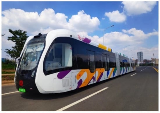
Figure 1.
Appearance of the multiunit articulated rubber-wheel autonomous rail rapid transit system.
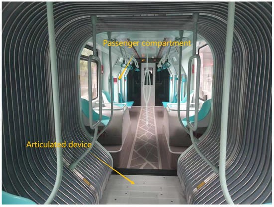
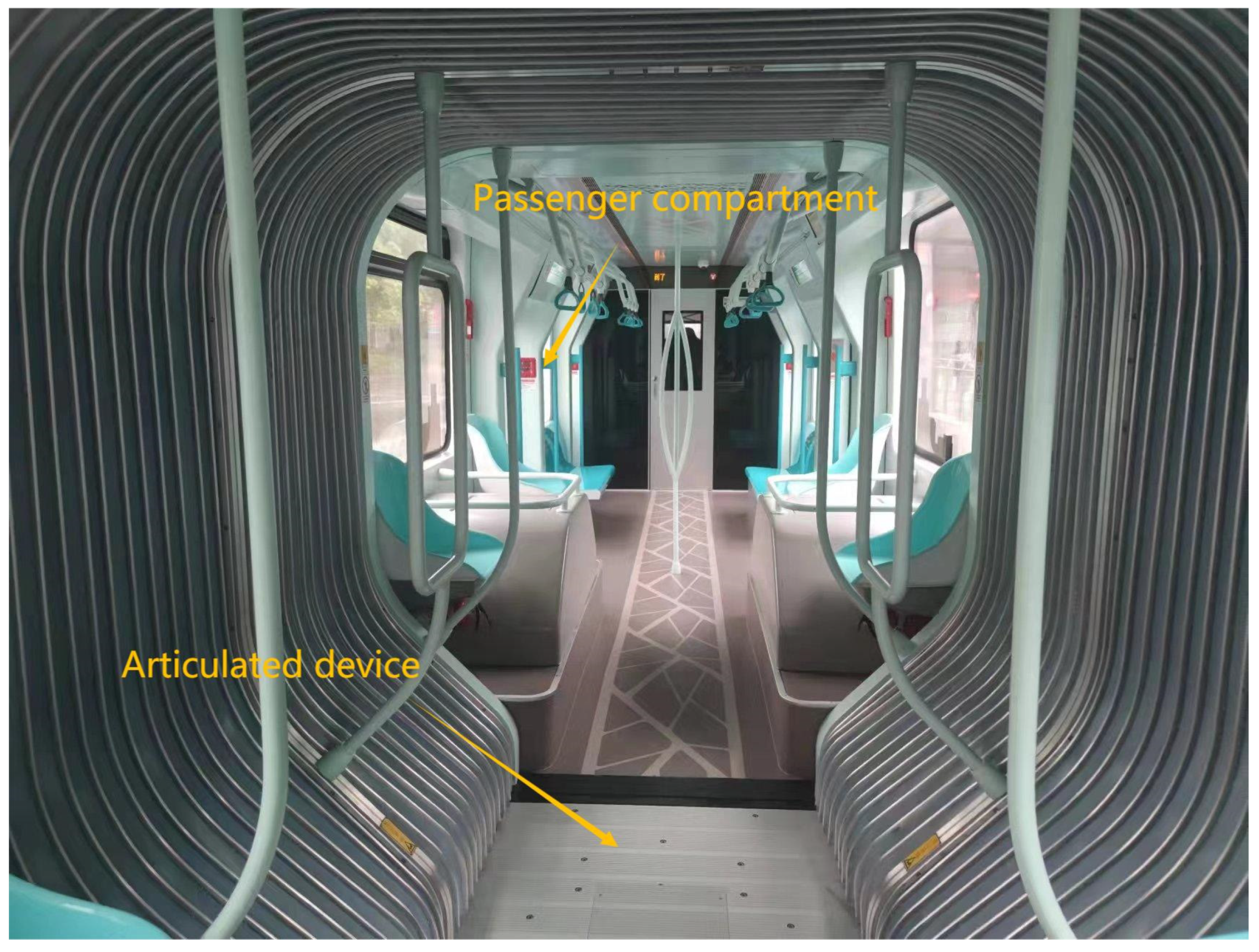
Figure 2.
Passenger compartment and articulated device of the multiunit articulated rubber-wheel autonomous rail rapid transit system.
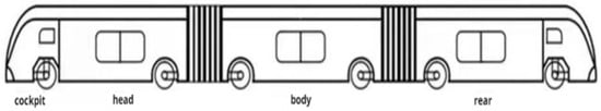
Figure 3.
Structure of a three-unit articulated rubber-wheel autonomous rail rapid transit system.

Figure 4.
Side view of the normal driving process of a multiunit vehicle.
When the multiunit vehicle brakes on the road, because of the influence of acceleration, force between the carriages, road conditions, and other factors, the transfer of axle load is inevitable. Therefore, the ground normal reaction forces of all the axles of the vehicle in the current state are different. When the multiunit vehicle applies a braking force, the wheel pair with the smallest ground normal reaction is more likely to be locked; that is, the sum of the braking force applied by the shaft and the hinged force of the carriage exceeds the ground adhesion constraint. This results in serious abrasions of the wheel and even swinging and folding. Therefore, the control of a vehicle’s ground normal reaction, articulation force, braking force distribution coefficient, and articulation angle is very important to exert the braking effect of the vehicle fully and to avoid unstable working conditions.
2.2. Model of Braking Dynamics of the Multiunit Vehicle
When the multiunit vehicle is in the emergency braking process, the front and rear wheel sets of each carriage will produce torque due to inertia, which will cause axle load transfer. For each wheel set of the same carriage, the ground normal reaction force is quite different. As the classic multiunit vehicle dynamics model is oversimplified in the calculation process, the constraint force of the model is insufficient, the number of independent equations is not enough during the force analysis, and the model is statically indeterminate. Therefore, when simplifying the dynamical model of the multiunit vehicles, some necessary constraints should be retained to make the model a static one so that the model can be more effectively used for the force analysis of the multiunit vehicles. Additionally, solving the frame as a rigid body in terms of the deformation compatibility equation or as a flexible body to solve using the energy strategy is difficult.
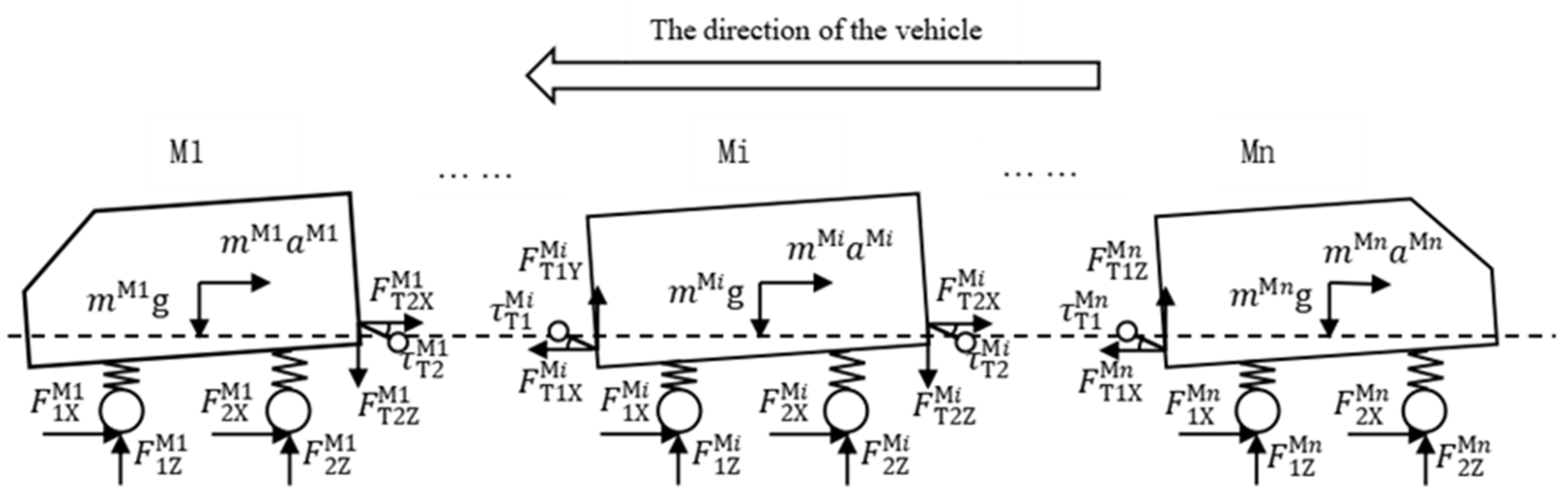
According to the above reasons, this paper introduces an approximate solution strategy for the multiunit vehicle load, that is, a multiunit vehicle emergency braking dynamic model with the suspension deformation compatibility equation and articulation force relationship equations, as shown in Figure 5 and Figure 6. Suppose that a frame is regarded as a constant rigid body, each suspension is reduced to a spring, and the stiffness is the equivalent stiffness of the suspension. The deformation of the suspension is constrained by the frame, and the suspension is forced, as shown in Figure 7. As the hinge disk at the vehicle connection is a rubber part and to make the multiunit vehicle drive on a sloped road, compared with the up and down swing angle generated by the load transfer when braking, the angle of the hinge swinging up and down is larger, so the hinge is not considered when braking. Therefore, each carriage is analyzed as a separate rigid body, and the force at the articulation point is used to indicate the pressure or tension of the front and rear carriages.

Figure 5.
Schematic of the braking process without considering load transfer.

Figure 6.
Schematic diagram of the braking process when considering load transfer.
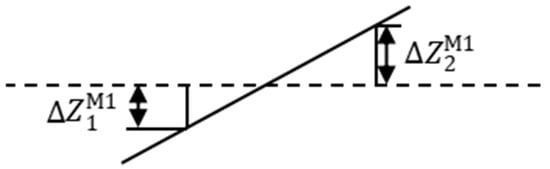
Figure 7.
Suspension force analysis diagram.
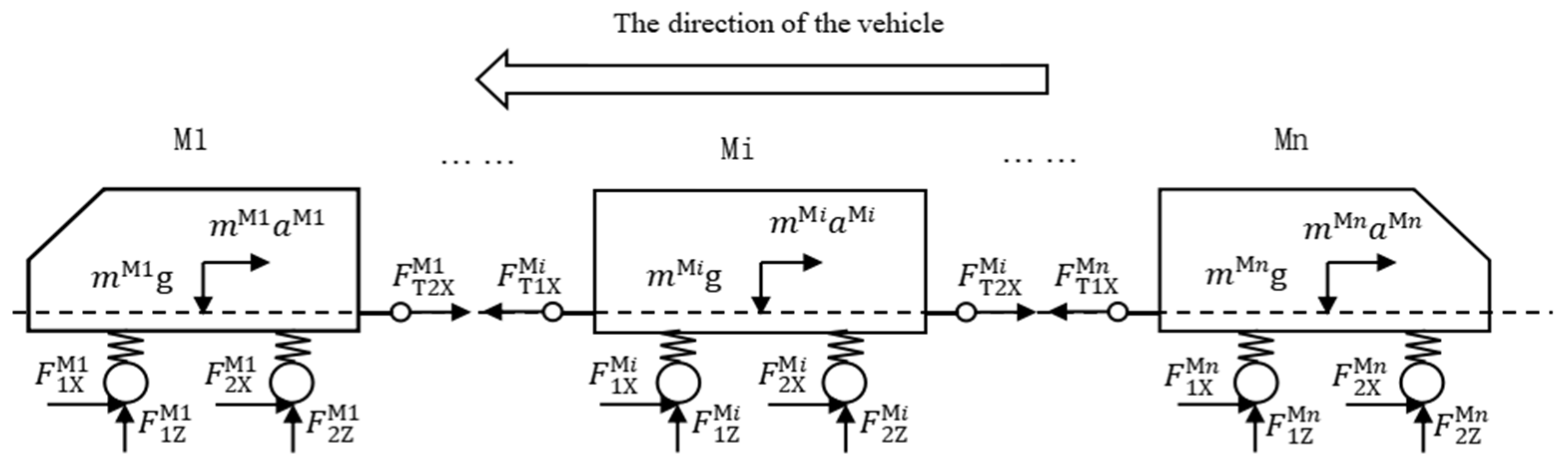
On the basis of the classical vehicle dynamics model and the front and rear hinges, the vehicle force balance equation is obtained for the multiunit vehicle braking on horizontal roads (Figure 5):
For the multiunit vehicle in the braking process with axle load transfer, the vehicle dynamics model considering front and rear articulated forces can be obtained through the vehicle torque balance equation (Figure 6):
In Equations (3) and (4), when i = 1, . When i = n, .
The independent force equation of the suspension due to load transfer is obtained from the suspension force analysis (Figure 7):
By analyzing the upper and lower deflection angles of the rear hinge of carriage Mi and the front hinge of carriage Mi + 1 caused by load transfer, the geometric angle equation of the rear hinge of carriage Mi can be obtained:
Force equation at the articulation:
2.3. Articulation Force Analysis Model for the Multiunit Vehicle
During the braking process of the multiunit vehicle, the braking deceleration of each carriage is different due to the different distribution of braking force, so the force will be generated at the articulation between carriages. Under the action of the articulated force, the braking deceleration of a single carriage is the same as the overall braking deceleration of a multiunit vehicle. When the articulation force is too large, the carriage is subject to lateral force due to the deflection angle, which is prone to instability; thus, it is important to solve the force at the articulation.
The direction of travel is specified as the positive direction. Stipulate m ∈ [1, n], the force balance equation of the whole vehicle in the X-axis direction is as follows:
Taking i = m as an example, when solving , the carriages form M1 to Mm are taken as a whole, and the force balance equation in the direction of the X-axis is listed:
The carriages from Mm + 1 to Mn behind are taken as a whole, and the X-axis direction force balance equation is as follows:
Calculate the hinge force of the X-axis at the Mm vehicle articulation :
3. Analysis of Linear Emergency Brake Instability of the Multiunit Vehicle
3.1. Analysis of the Emergency Braking Instability Characteristics of the Multiunit Vehicle
When a multiunit vehicle brakes in an urgent situation, a large braking force is assigned to achieve a better braking effect, but the lateral force that can be distributed by the tire is very small. Under emergency braking conditions, the force on the tire can easily exceed the maximum ground adhesion, resulting in serious instability conditions such as skidding, tail swinging, and carriage folding. Therefore, the multiunit vehicles put forward higher requirements for controlling the influencing factors that may cause instability, such as the articulation force, the braking force distribution coefficient, the maximum lateral force that the tire can withstand during braking, and the left and right swing angles at the front and rear articulations. Moreover, when a certain section of a vehicle is affected by instability factors, the tire produces lateral forces, and the front and rear articulations of the vehicle may produce left and right declination angles. These are divided into three types: Declination angles at the front articulation, at the rear articulation, and at both the front and rear articulations. The first two cases are more common, and the third situation is used as the main analysis model.
3.2. Modeling of Emergency Braking Instability Conditions of the Multiunit Vehicle
According to Section 3.1, the corresponding dynamic model is established according to the analysis of the characteristics of the emergency braking instability of the multiunit vehicle.
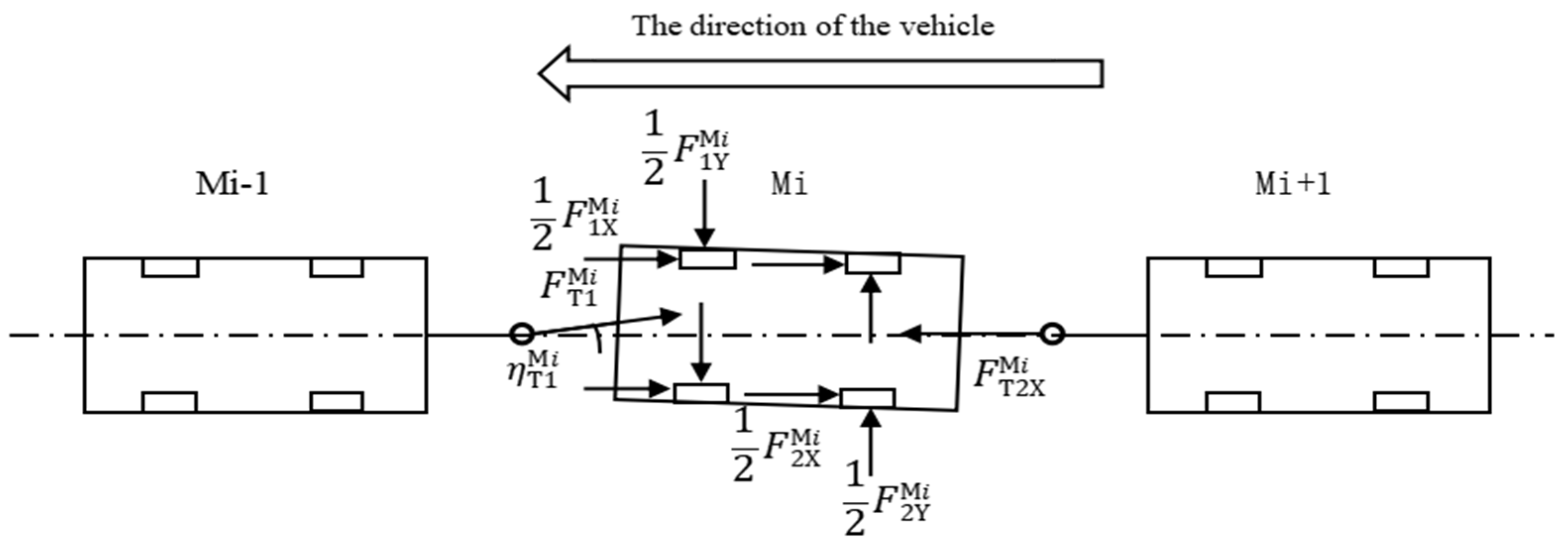
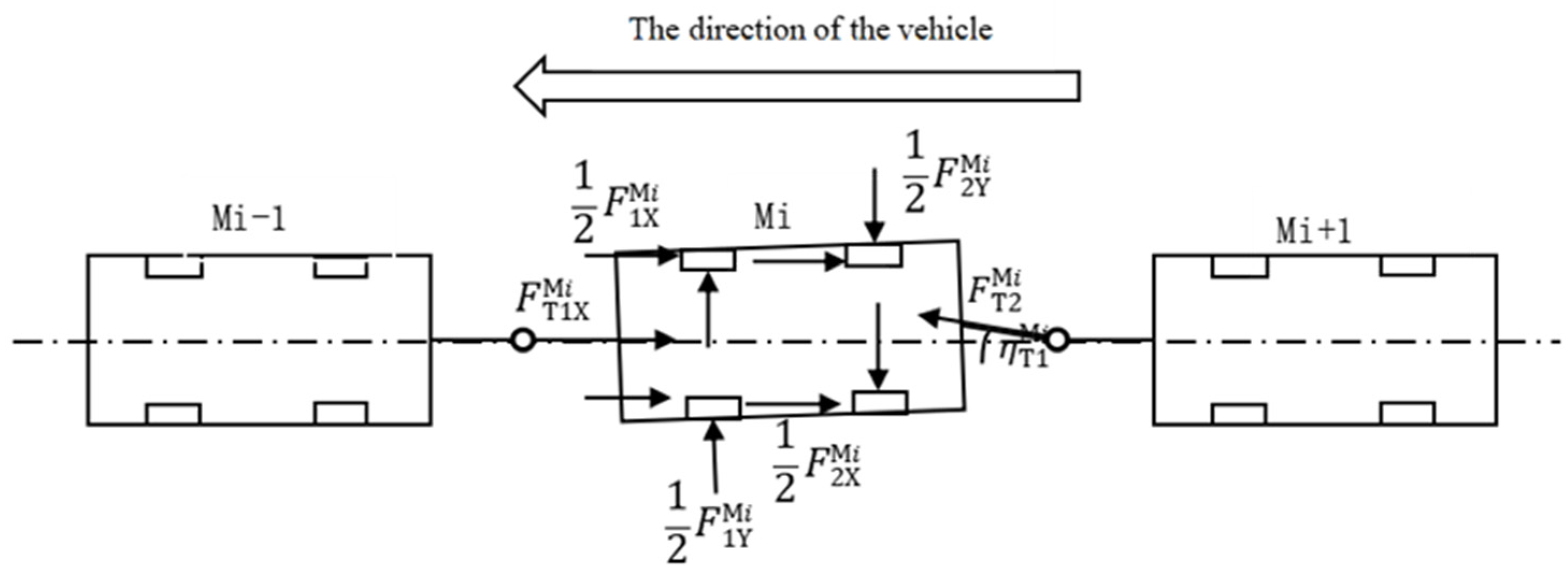
The force balance equation of a single carriage can be obtained by analyzing the dynamic models of the emergency braking instability of the three kinds of the multiunit vehicles described above (Figure 8, Figure 9 and Figure 10).

Figure 8.
Dynamic model of the emergency braking instability of a vehicle with a declination angle generated at the front articulation.

Figure 9.
Dynamic model of the emergency braking instability of a vehicle with a declination angle generated at the rear articulation.
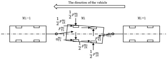
Figure 10.
Dynamic model of a vehicle emergency braking instability condition with declination angles at both the front and rear articulations.
Single-carriage torque balance equations:
Tire force balance equations:
Equation of force relationship at the articulation:
3.3. Critical Conditions for the Emergency Braking Instability of the Multiunit Vehicle
In the process of emergency braking, the multiunit vehicle is prone to angle changes and body oscillations that result in lateral forces. Therefore, calculating the maximum value of the lateral force of each axle tire corresponding to this acceleration case is necessary. is the critical condition of instability and relates to angle and braking acceleration . Thus, it is necessary to find the relational equation between them for optimization.
From Formulas (13) and (16), we can obtain Formulas (26) and (27). The following shows the force equations for of the articulation of the carriage Mm−1 and of the articulation of the carriage Mm:
The hinge point for the carriage Mm − 1 and that for the carriage Mm refer to the same articulation point:
When a vehicle is subjected to the force at the articulation, the force in the direction of the Y-axis is caused by the pendulum angle:
Equations (18)–(21) are used to obtain the magnitude of the lateral force of the tire caused by the Y-axis force at the articulation of the carriage Mi:
The following are the general calculation formulas for the lateral forces on the front and rear axle tires of the carriage Mi:
According to the maximum braking force that can be provided by the ground adhesion coefficient and the distribution of the braking force on each axle, the maximum value of the lateral force that can be provided by the tires of each axle is determined:
Thus, the maximum lateral forces of the front and rear axle tires of carriage Mi are as follows:
According to Formulas (33), (34), (37) and (38), the conditions for determining instability during the emergency braking conditions of the multiunit vehicles are as follows:
4. Active Control Strategies for the Linear Emergency Braking of the Multiunit Vehicle
4.1. Solution of the Ground Braking Force of the Multiunit Vehicle
Braking deceleration is the derivative of the vehicle speed to time during braking (i.e.,). It reflects the amount of ground braking force and is therefore related to the braking force (when the wheel is rolling) and adhesion (when the wheel is locked and dragged).
On different pavements, the ground braking force is
Therefore, the deceleration () that the vehicle can achieve is
If the front and rear wheels are locked at the same time, then
If there is an ideal brake antilock device to control the vehicle brake, then
The braking distance of the multiunit vehicles is closely related to driving safety. Before its calculation, it is necessary to understand the deceleration of the brake and the relationship between the braking force of the brake and the braking time. The linear function of the braking force over time is as follows:
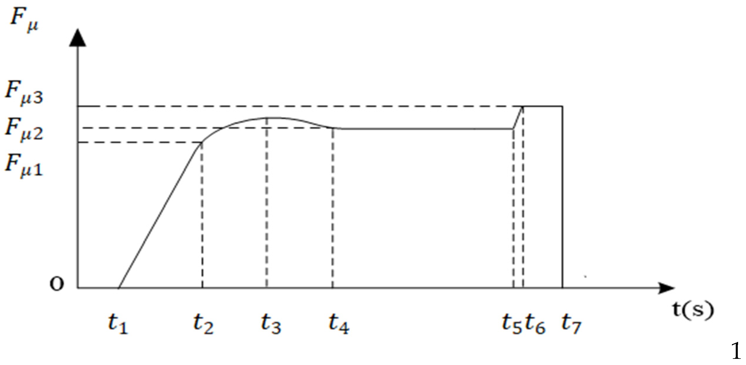
As shown in Figure 11, is the reaction time of the brakes. At time , the brakes begin to act. Over time , the braking force continues to grow at a slope of . When the time point is reached, the growth rate of begins to decrease because of the impact of the shaft core shift on each vehicle. As the braking deceleration increases with the continuous increase in braking force, the vehicle may be in danger of side-slipping at the time point . Therefore, at this time, the braking force is appropriately reduced to avoid danger. At time , the braking force is in a stable state. When the speed drops to 10 km/h, the vehicle begins to hug (i.e., at time ), until it reaches (when the vehicle is all hugged), slowing down smoothly to stop at when is the sliding attachment coefficient .
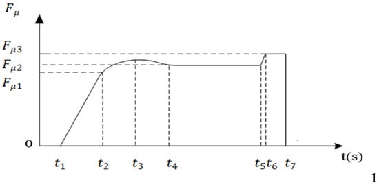
Figure 11.
Braking force-time curve.
4.2. Construction of a Multiunit Vehicle Braking Distance Model
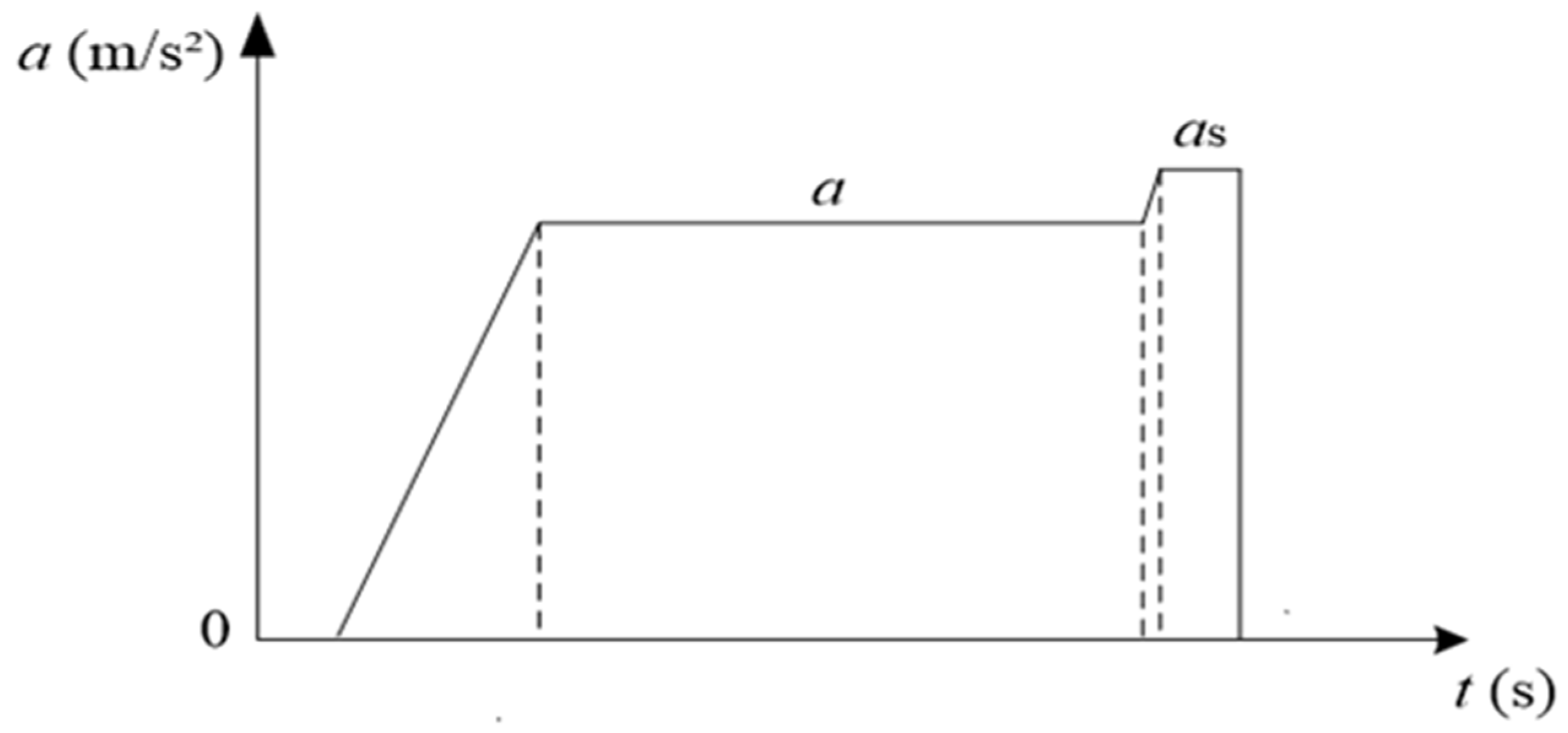
The solution for acceleration is simplified because the braking force is subject to small changes in magnitude and short time due to axle load transfer and safety considerations. The relation curve between deceleration and time is shown in Figure 12.

Figure 12.
Braking deceleration-time curve.
is the reaction time of the brake, is the time taken as the braking deceleration increases with the braking force, and is the braking duration. When the speed drops to 10 km/h, the vehicle starts to lock. At time point , the speed is 10 km/h. At the time point , the entire vehicle is locked. is the time required for the vehicle to hold and drag to a stop.
During ,
Integrate over time because it is in time , , so
Integrate again:
Therefore, the speed in time point is
Thus, obtained using Equations (46) and (49), the braking distance in time is
Substitute Formula (51) into Formula (52),
In the continuous stage, the constant deceleration is unchanged, the initial speed is , and the final speed is h. Therefore,
At time , the deceleration continues to increase, and the distance within the same time can be solved:
In the continuous stage , the constant deceleration is unchanged, the initial speed is , and the final speed is 0. Therefore,
Thus, the total braking distance is
Substitute Formulas (53)–(56) into Formula (57)
As the times and are very short, i.e., and . Therefore,
Substitute Formula (50) into Formula (59) and equals the initial velocity ,
4.3. Emergency Braking Control Strategy for the Multiunit Vehicle
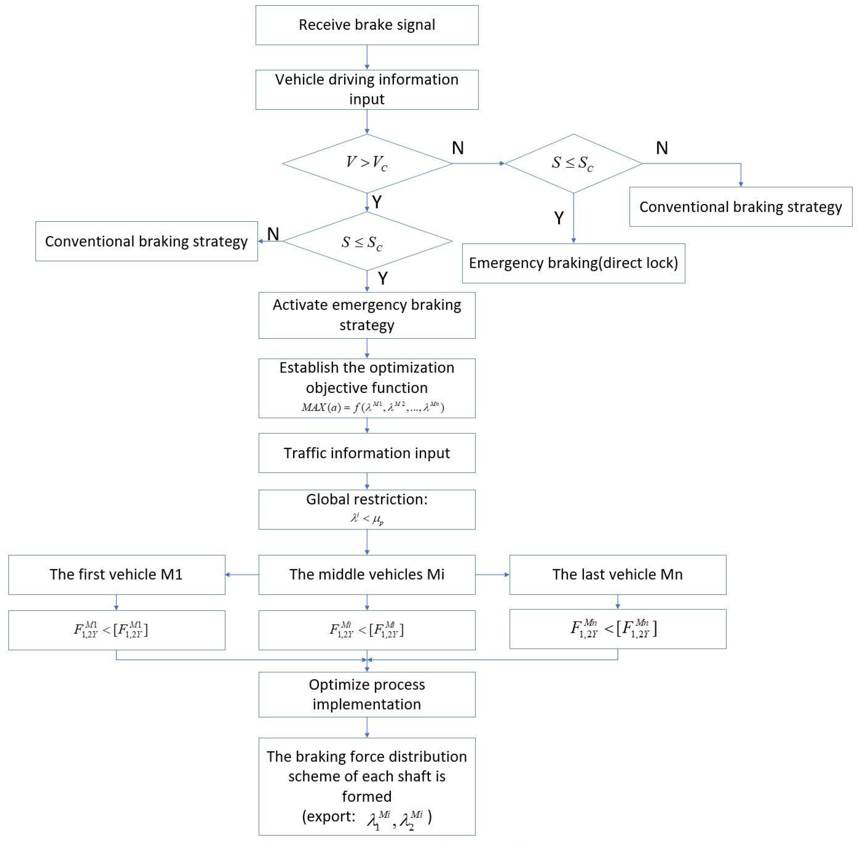
Using the relationship between the speed and braking distance that has been solved, the emergency braking control strategy of a multiunit vehicle can be judged and selected to ensure driving safety. The braking process can be controlled according to the workflow shown in Figure 13.
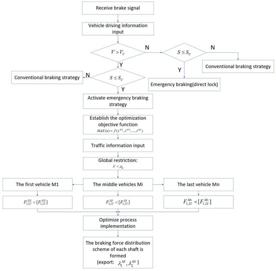
Figure 13.
Emergency braking control strategy for the multiunit vehicle.
5. Simulation of the Emergency Braking Control Process of Three-Unit Vehicle
5.1. Simulation Model Establishment
In this paper, the establishment of the dynamic model of emergency braking and the construction of the dynamic simulation platform for three-unit vehicle was based on the MATLAB/Simulink platform. Simulink is a visual simulation tool in MATLAB and is one of the most famous simulation integration environments in the field of dynamic system simulation. Users can quickly build their own dynamic system simulation models in this environment. For this simulation analysis, the Simulink operation is simple and intuitive as a complex system can be constructed by simply dragging and dropping modules. Given the above characteristics of MATLAB/Simulink, it was selected as the platform environment for modeling and simulation in this study.
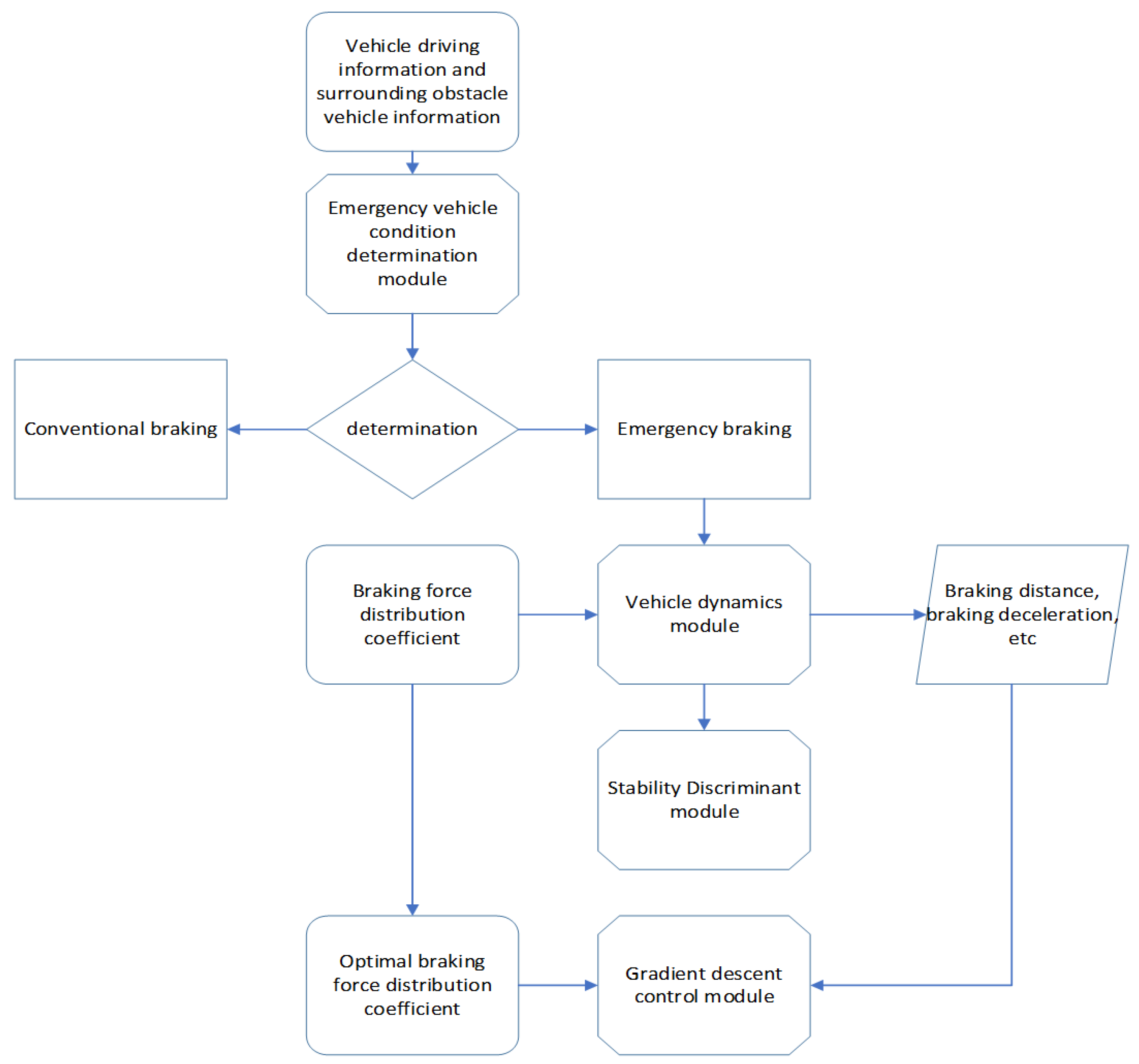
The simulation model of the emergency braking control process of the three-unit vehicle in this paper mainly consists of these four parts:
- (1)
- Emergency vehicle condition determination module. This module includes a longitudinal safety distance determination module and a braking speed determination module. When a vehicle is located directly in front of the self-driving vehicle, the latter mainly determines whether there is a risk of collision by using the longitudinal relative distance and longitudinal relative speed of the two combined with the driving speed of the self-driving vehicle. When the vehicle receives a braking signal, the emergency vehicle condition determination module receives real-time information on the vehicle’s operating conditions and the surrounding obstacle vehicles obtained by the on-board sensor. It then obtains a certain amount of information that can indicate the degree of danger according to the calculation strategy designed in advance. The degree of danger is determined after comparing the obtained information with the set threshold, which then determines whether the emergency braking program should be activated. The entire module eventually outputs zero or one depending on the value of the input signal. When the module outputs one, the emergency braking system can be triggered. Otherwise, it makes the vehicle brake according to the conventional braking strategy.
- (2)
- Vehicle dynamics module. This module analyzes the ground braking force, ground lateral reaction force, ground normal reaction force, and the X-, Y-, and Z-direction forces at the articulation of the multiunit vehicles during emergency braking. This is done by introducing the suspension deformation compatibility equation, the articulation force relationship equation, the tire force balance equation, and so on. Thus, the vehicle braking force, braking deceleration, and braking distance corresponding to the different braking force distribution coefficients of the vehicle are obtained. This paper examined the braking process of the multiunit vehicles in an ideal state so that the sum of the braking force distribution coefficients of each vehicle’s front and rear axles is one.
- (3)
- Stability discriminant module. By analyzing the emergency braking instability characteristics of the multiunit vehicles, this module mainly examines the tire lateral forces of the front and rear axles in the case of left and right declination angles at the front and rear articulations, as well as the stability of the vehicle. With the maximum tire lateral force, the vehicle remains stable when the tire lateral force is less than the maximum tire lateral force; otherwise, the vehicle is unstable. The ultimate goal of this paper is to obtain an emergency brake control model that enables the multiunit vehicles to achieve braking at the shortest braking distance while maintaining stability and to output the optimal braking force distribution coefficient at this time. Therefore, stability discrimination for the multiunit vehicles is particularly important.
- (4)
- Gradient descent control module. This paper mainly studies the emergency braking control process of three-unit vehicles. Thus, it features the multiple parameters of the braking force distribution coefficient of three-unit vehicles. Considering the optimization problem of multiple parameters is necessary to achieve optimal braking for the multiunit vehicles, that is, to achieve the braking force distribution coefficient with the shortest braking distance while ensuring stability. Gradient descent is the simplest and most effective algorithm to solve convex optimization problems and has important applications in engineering practice, such as parameter identification, machine learning, and optimization control. By using the gradient descent strategy, the module obtains a braking force distribution coefficient that can achieve optimal braking and is sent to the brake controller so that each shaft distributes the braking force according to the partition coefficient, thereby completing the braking.
Figure 14 shows the simulation model of the emergency braking of the three-unit vehicle, of which the four rectangles with cutting edges represent the four main modules of the simulation model discussed above.
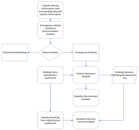
Figure 14.
Simulation model of emergency braking for a three-unit vehicle.
5.2. Simulation Parameter Settings
With the autonomous rail rapid transit as the prototype, and a simulation environment of dry asphalt or concrete pavement, the emergency braking simulation model of a three-unit articulated rubber-wheel train is established. Relevant parameter settings are shown in Table 1, in which the center of the mass of each carriage is under the condition of no load of the vehicle.

Table 1.
Relevant parameter settings of the simulation model.
5.3. Simulation of the Emergency Braking Control Process of Three-Unit Vehicle
The simulation part of this study is mainly divided into three parts. First, the influence of the braking force distribution coefficient of the front and rear axles on the braking performance is studied. Second, the relationship between the deformation of the front and rear axle suspension and the braking performance is studied. Finally, the influence of the position of the carriage’s center of mass on the braking performance is studied. As there are too many parameters, the change curve of braking performance in the first two parts of the simulation, is visually simulated by setting some of the parameters as equal, as discussed in detail below.
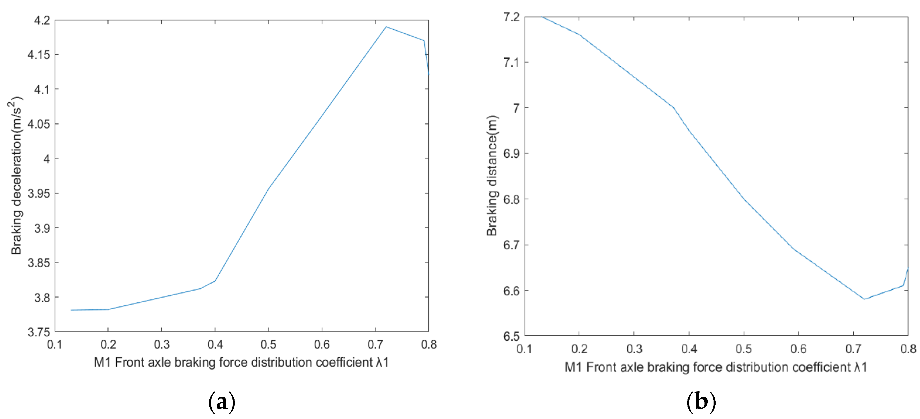
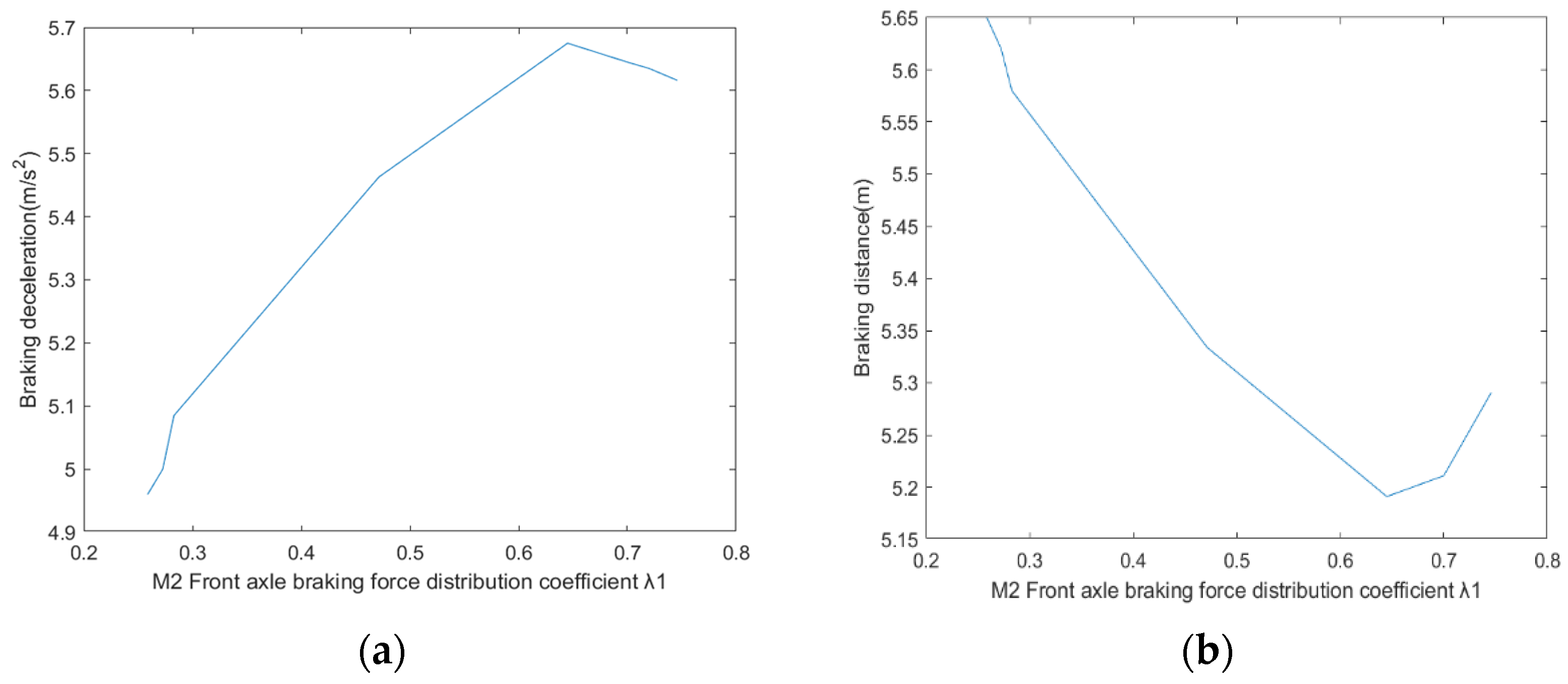
The braking force distribution coefficient of each carriage of a multiunit vehicle can be distributed artificially. The relationship between the braking performance and the braking force distribution coefficient of the front and rear axles of each carriage is determined by performing the following simulations. The initial speed of the vehicle is set at 30 km/h, and emergency braking is activated. The braking force distribution coefficient of carriages M2 and M3 () is set as a certain constant to reflect the above relationship more intuitively. The variation curves of braking deceleration and braking distance with respect to the braking force distribution coefficient of the front axle of carriage M1 () can be obtained, as shown in Figure 15. Similarly, we can obtain the variation curves of braking deceleration and braking distance concerning the braking force distribution coefficient of the front axle of carriage M1 () when the braking force distribution coefficient of carriages M1 and M3 () is set as a certain constant, as shown in Figure 16.
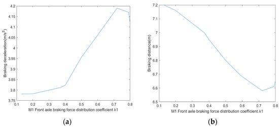
Figure 15.
Variation curve of braking performance with : (a) Braking deceleration change curve; (b) braking distance change curve.
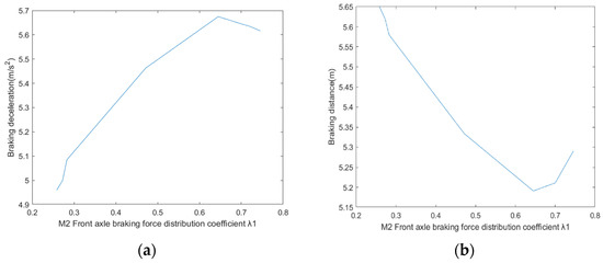
Figure 16.
Variation curve of braking performance with : (a) Braking deceleration change curve; (b) braking distance change curve.
As shown in Figure 15, when are fixed as constants, the braking distance decreases roughly with the increase in under the condition of ensuring vehicle stability within a certain range (0.15–0.72), and the corresponding braking deceleration gradually increases. As shown in Figure 16, the braking distance decreases roughly with the increase of under the condition of ensuring vehicle stability within a certain range (0.25–0.63) when are fixed as constants. Here, the corresponding braking deceleration gradually increases. When exceed the above range and increase continuously, the vehicle becomes unstable, which in turn affects the braking performance of the vehicle. Thus, this control model can be used to obtain the braking force distribution coefficient that allows the vehicle to be brake at the shortest distance while maintaining stability.
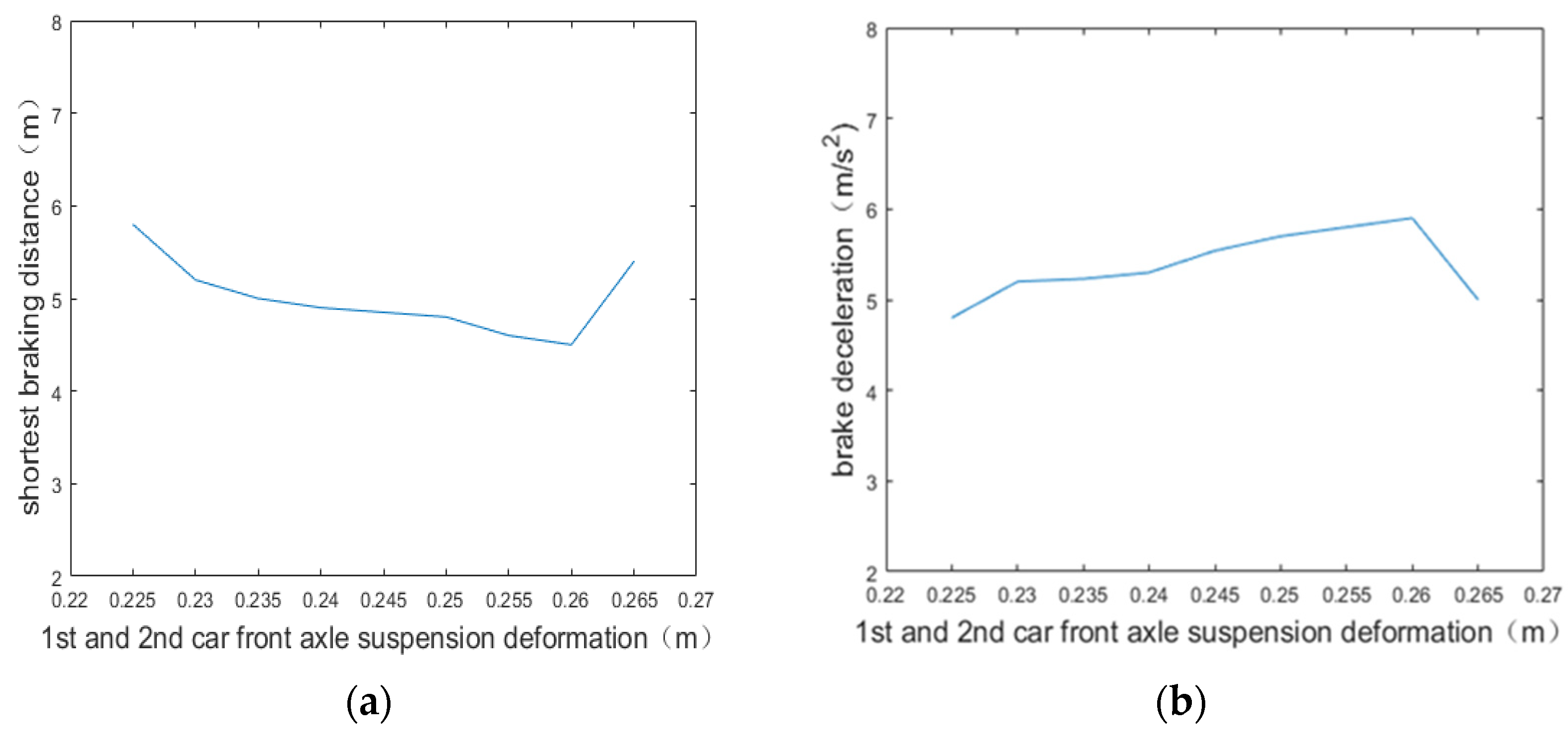
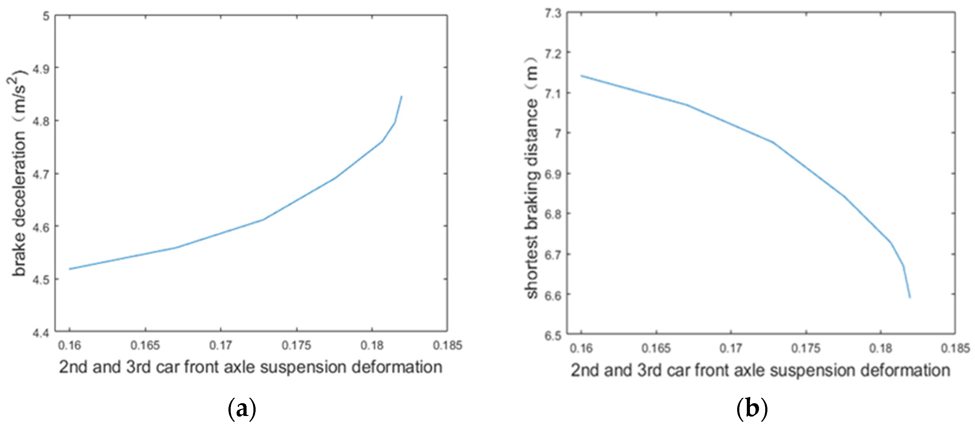
When a multiunit vehicle is in the process of emergency braking, the braking force distribution coefficient of the front and rear axles of each carriage () and the suspension deformation of the front and rear axles of each vehicle () are in a one-to-one correspondence. That is, when is determined, the is also determined. Therefore, studying the relationship between the braking distance, braking deceleration, and is also possible. For a more intuitive reflection of this relationship, the suspension deformations of the front axle of the carriages and can be made equal (i.e., ), we can obtain the optimal braking parameters under the condition of by constantly changing the amount of suspension deformation of the carriage , i.e., . The shortest braking distance change curve and braking deceleration change curve are obtained, as shown in Figure 17. Similarly, we can equal the suspension deformations of the front axles of carriages and , i.e., . The suspension deformation of the front axle of carriage , i.e., is constantly changed to seek the optimal braking parameters at this time and obtain the change curves of the shortest braking distance and braking deceleration, as shown in Figure 18. The parameters are set as follows: The initial speed of the vehicle is 30 km/h, and the center of mass of each vehicle does not shift forward and backward.
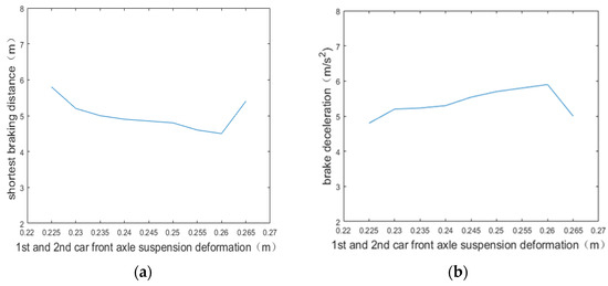
Figure 17.
Variation curve of braking performance with : (a) Shortest braking distance change curve; (b) braking deceleration change curve.
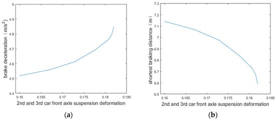
Figure 18.
Variation curve of braking performance with : (a) Braking deceleration change curve; (b) shortest braking distance variation curve.
From Figure 17 we can observe that the optimal braking parameters can be obtained by continuously changing with the condition of , the shortest braking distance decreases with the increase in within a certain range (0.223–0.262), and the braking deceleration increases with the increase in within a certain range (0.223–0.262). However, when exceeds a certain critical value, the vehicle becomes prone to instability because of the excessive suspension deformation, which in turn affects the braking effect. As shown in Figure 18, the shortest braking distance under the condition of decreases with the increase in within a certain range, and the braking deceleration increases with the increase in within a certain range. Through the above simulation experiments, the relationship between the braking distance, braking deceleration, and suspension deformation is obtained, and a certain relationship between the braking distance, braking deceleration, and braking force distribution coefficient is obtained.
Due to the inertia of multiunit vehicles during emergency braking and the uneven distribution of passengers in carriages, the position of the centroid of each vehicle is not fixed, which is mainly manifested in the centroid forward or backward. When the position of the center of mass changes, the braking effect achieved under the same braking force distribution coefficient conditions is different, and the stability performance of the vehicle will also be different. Thus, the emergency braking situation of a vehicle must be studied under different center of mass positions. The best braking force distribution coefficient for braking with the shortest braking distance while ensuring the stability of the vehicle can be obtained using the gradient descent strategy. When the vehicle centroid position moves forward or backward, the changes in the braking distance and braking deceleration obtained from the simulation model to achieve optimal braking are shown in Table 2.
Table 2.
Optimal braking experimental results with changes in the centroid position.
As shown in Table 2, when the centroid is in different positions, the vehicle can achieve the shortest braking distance and deceleration while ensuring stability, which is roughly , , and , respectively, indicate that the vehicle centroid moved forward, moved backward, and remained unchanged. While the center of mass can be moved backward to a certain extent and the braking distance can be reduced, the distance between the front and back movement of the vehicle’s center of mass cannot be too large. Otherwise, the vehicle is prone to instability during emergency braking, which is also an important parameter that must be considered when designing the vehicle. In addition, the braking distance decreases roughly with an increasing front axle braking force distribution coefficient. At the same time, the impact of braking force distribution coefficient on the stability of the vehicle must be considered, and the braking must be achieved while ensuring stability.
6. Experiments
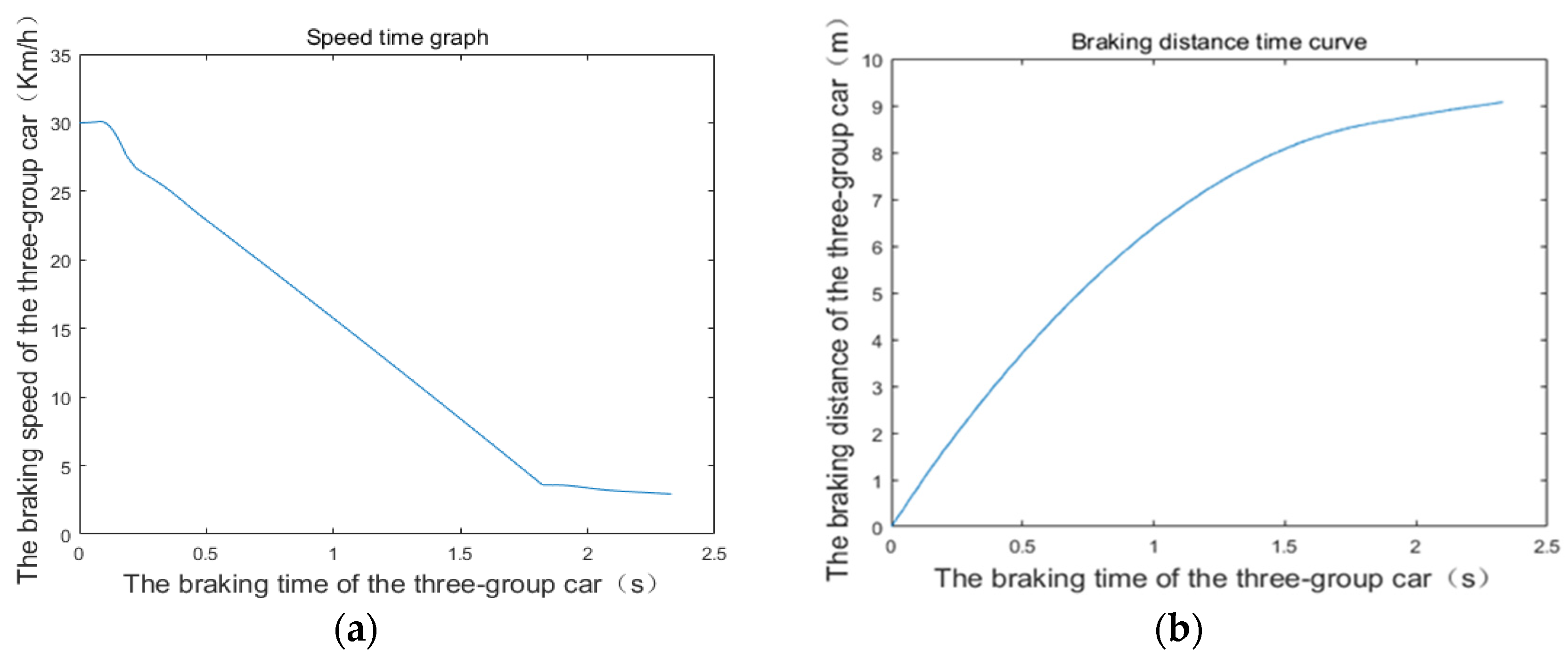
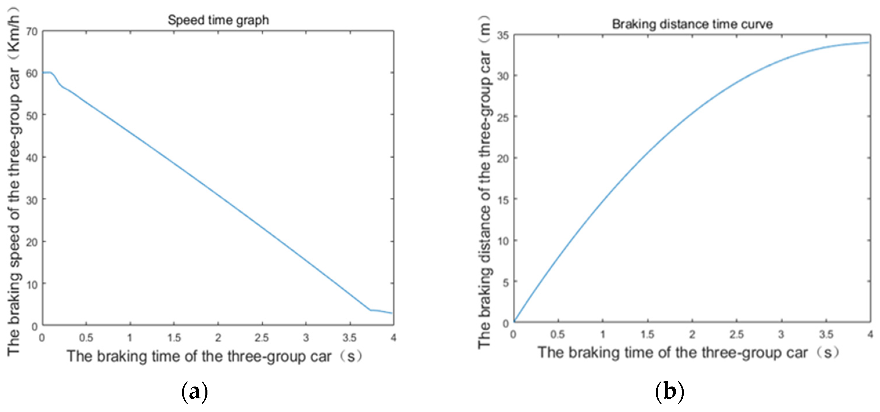
Emergency braking and control experiments are conducted using a three-unit articulated rubber-wheel autonomous rail rapid transit system at an initial speed of 30 km/h and 60 km/h to verify the brake dynamics model and the effect of the active control strategy. Figure 19 shows the braking curves at an initial speed of 30 km/h, whereas Figure 20 shows the braking curves at an initial speed of 60 km/h. As shown in Figure 19a, after a short braking reaction time, the braking deceleration changed rapidly and linearly with time. The speed dropped to below 4 km/h in 1.56 s, which then gently and gradually changed to zero. At that time, the system stopped after braking. Moreover, the braking curve showed no obvious instability. From Figure 19b, the braking distance increased rapidly in the early stage and flattened out after 1.5 s. Finally, the optimal braking distance under active control gradually stabilized at about 9 m. As shown in Figure 20, the braking curve at an initial speed of 60 km/h is similar to that at an initial speed of 30 km/h, except that the braking distance and braking time become larger.
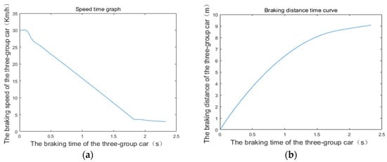
Figure 19.
Variation curve of braking performance with time when the initial velocity is 30 km/h: (a) Braking speed change curve; (b) braking distance change curve.
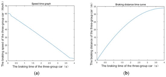
Figure 20.
Variation curve of braking performance with time when the initial velocity is 60 km/h: (a) Braking speed change curve; (b) braking distance change curve.
The real vehicle experiments show that the dynamics model can reflect the multiunit articulated rubber-wheel autonomous rail rapid transit system’s brake instability well, and the braking effect of the active control strategy also meets the needs of engineering applications.
7. Conclusions
In this paper, the dynamic model of a multiunit articulated rubber-wheel autonomous rail rapid transit system under emergency braking condition is built, and the active control strategy of emergency braking is proposed by the stability analysis.
The simulation results show that the brake force distribution coefficient and the suspension deformation have an influence on the braking performance. Within a certain range, the braking distance generally decreases with the increase in the front axle brake force distribution coefficient and the suspension deformation. However, when the braking force distribution coefficient of the front axle and the suspension deformation continue to increase, the stability of the vehicle will be affected in turn, and then the braking performance will be affected. In addition, the position of the center of mass of the vehicle’s carriage also has an impact on the braking performance. Proper back movement of the center of mass can improve the braking performance of the vehicle, which is also an important factor that must be considered in the body design. At the same time, the control of vehicle’s body posture is the key to shorten the braking distance.
The experimental results show that the emergency braking dynamic model can approximate the actual braking process of the multiunit articulated rubber-wheel autonomous rail rapid transit system well. The braking distance and braking time also show that the proposed control strategy is feasible.
This paper presents an accurate dynamic model and a suitable active control strategy for the emergency braking process in a multiunit articulated rubber-wheel autonomous rail rapid transit system. Additionally, it can also provide useful information to avoid the instability risk of the multiunit vehicle, ensure the safety of passengers, and develop the urban transportation system. In the future, the dynamic characteristics of the nonlinear region of the tire will be further considered, combined with the impact of the squeeze pressure between the carriages on the vehicle’s body posture, to achieve a more comprehensive braking strategy design.
Author Contributions
Conceptualization, T.L., S.Z. and M.W.; Data curation, T.L., S.Z. and M.W.; Formal analysis, T.L., S.Z. and M.W.; Funding acquisition, T.L. and G.X.; Investigation, T.L., H.Z. and J.F.; Methodology, T.L., S.Z., G.X. and M.W.; Project administration, T.L. and G.X.; Resources, T.L. and S.Z.; Software, T.L.; Supervision, T.L.; Validation, T.L., H.Z. and J.F.; Visualization, S.Z. and M.W.; Writing—original draft, T.L., S.Z., G.X. and M.W.; Writing—review & editing, T.L., S.Z., G.X., M.W., H.Z. and J.F. All authors have read and agreed to the published version of the manuscript.
Funding
The research was funded by Natural Science Foundation of Hunan Province (grant number 2022JJ30019), National Natural Science Foundation of China (grant number 52075159), the Open foundation of Guangxi Key Laboratory of Processing for Non-ferrous Metals and Featured Materials, Guangxi University (grant number 2022GXYSOF24), Virtual Reality Key Application Technology Research (Revealed and Commanded) Project of Jiangxi Province (grant number 20220173), and the Postgraduate Research and Innovation Project of Hunan University of Technology (grant number CX2011).
Institutional Review Board Statement
Not applicable.
Informed Consent Statement
Not applicable.
Data Availability Statement
The data presented in this study are available on request from the corresponding author.
Acknowledgments
We would like to thank Yuyao He and Lei Xiao for their suggestions based on which this paper has been greatly improved.
Conflicts of Interest
The authors declare no conflict of interest. The funders had no role in the design of the study; in the collection, analyses, or interpretation of data; in the writing of the manuscript; or in the decision to publish the results.
Abbreviations
| Carriage Mi mass (kg); | |
| Acceleration due to gravity (m/); | |
| Carriage Mi braking deceleration (m/); | |
| Average braking deceleration (m/) of the carriages from M1 to Mn; | |
| Average braking deceleration (m/) of the carriages from M1 to Mm; | |
| Average braking deceleration (m/) of the carriages from Mm+1 to Mn; | |
| Ground braking force (N) on the front and rear axles of the carriage Mi; | |
| Ground lateral reaction force (N) on the front and rear axles of the carriage Mi; | |
| Ground normal reaction force (N) on the front and rear axles of the carriage Mi; | |
| X-directional force (N) at the front and rear articulations of the carriage Mi; | |
| Y-directional force (N) at the front and rear articulations of the carriage Mi; | |
| Z-directional force (N) at the front and rear articulations of the carriage Mi; | |
| Total ground braking force (N) of the carriages from M1 to Mn; | |
| Total braking force (N) of the carriages from M1 to Mm and the carriages from Mm+1 to Mn; | |
| , | Front and rear hinges of the carriage Mi with a horizontal angle (°); |
| Front and rear hinges of the carriage Mi with left and right angles to a horizontal plane (°); | |
| Braking force distribution coefficient for the front and rear axles of the carriage Mi; | |
| Rolling attachment coefficient; | |
| Maximum ground adhesion coefficient; | |
| Equivalent stiffness of the axle suspension (N/m); | |
| Horizontal distance between the two axles of the carriage Mi (m); | |
| Horizontal distance from the center of mass to the front and rear axle centerlines of the carriage Mi (m); | |
| Length of hinges between vehicle carriages (m); | |
| Articulation to the nearest adjacent axis (m); | |
| Distance from the center of mass of the carriage Mi to the ground (m); | |
| Distance from the front articulation to the ground and from the rear articulation to the ground (m); | |
| Amount of deformation of the front and rear axle suspensions of the carriage Mi (m). |
References
- Lei, T.; Wang, J.; Yao, Z. Modelling and stability analysis of articulated vehicles. Appl. Sci. 2021, 11, 3663. [Google Scholar] [CrossRef]
- Wei, L.; Zeng, J.; Qu, S.; Huang, C.; Wang, Q. Longitudinal-vertical dynamics of a high-speed train rescued by locomotives during braking on grades. Veh. Syst. Dyn. 2022, 1–24. [Google Scholar] [CrossRef]
- Garcia-Bedoya, O.; Hirota, S.; Ferreira, J.V. Control system design for an automatic emergency braking system in a sedan vehicle. In Proceedings of the 2nd Latin American Conference on Intelligent Transportation Systems (ITS LATAM), Bogota, Colombia, 19–20 March 2019; pp. 1–6. [Google Scholar]
- Liu, Y.; Zhou, Y.; Su, S.; Xun, J.; Tang, T. Control strategy for stable formation of high-speed virtually coupled trains with disturbances and delays. Comput.-Aided Civ. Infrastruct. Eng. 2022. [Google Scholar] [CrossRef]
- Wu, Q.; Cole, C.; Spiryagin, M.; Chang, C.; Wei, W.; Ursulyak, L.; Shvets, A.; Murtaza, M.A.; Mirza, I.M.; Zhelieznov, K.; et al. Freight train air brake models. Int. J. Rail Transp. 2021, 1–49. [Google Scholar] [CrossRef]
- Zong, C.; He, J.; Yang, J.; Li, X. Research on correlation between static and dynamic braking performance characteristics of articulated vehicle. In Proceedings of the 2021 6th International Conference on Transportation Information and Safety (ICTIS), Wuhan, China, 22–24 October 2021; pp. 1532–1539. [Google Scholar]
- Ataei, M.; Khajepour, A.; Jeon, S. Model predictive control for integrated lateral stability, traction/braking control, and rollover prevention of electric vehicles. Veh. Syst. Dyn. 2020, 58, 49–73. [Google Scholar] [CrossRef]
- Termous, H.; Shraïm, H.; Talj, R.; Francis, C.; Charara, A. Coordinated control strategies for active steering, differential braking and active suspension for vehicle stability, handling and safety improvement. Veh. Syst. Dyn. 2019, 57, 1494–1529. [Google Scholar] [CrossRef]
- Skotnikov, G.I.; Jileykin, M.M.; Komissarov, A.I. Increasing the stability of the articulated lorry at braking by locking the fifth wheel coupling. In IOP Conference Series: Materials Science and Engineering, Proceedings of the International Automobile Scientific Forum (IASF-2017) Intelligent Transport Systems, Moscow, Russia, 18–19 October 2017; IOP Publishing: Bristol, England, 2018; Volume 315, p. 012027. [Google Scholar]
- Gao, Z.; Li, D.; Xie, L. Study on the differential braking of an eddy current retarder axle used for articulated vehicles. In Proceedings of the IEEE 5th International Conference on Intelligent Transportation Engineering (ICITE), Beijing, China, 11–13 September 2020; pp. 596–600. [Google Scholar]
- Dudziński, P.; Skurjat, A. System for improving directional stability for articulated vehicles. In AIP Conference Proceedings, Proceedings of the 15th Conference on Computational Technologies in Engineering, Jora Wielka, Poland, 16–19 October 2018; AIP Publishing LLC: New York, NY, USA, 2019; Volume 2078, p. 020084. [Google Scholar]
- Zhang, Y.; Khajepour, A.; Ataei, M. A universal and reconfigurable stability control methodology for articulated vehicles with any configurations. IEEE Trans. Veh. Technol. 2020, 69, 3748–3759. [Google Scholar] [CrossRef]
- Sharma, S.K.; Kumar, A. Impact of longitudinal vehicle dynamics on vehicle operations: A simulation-based study. J. Vib. Eng. Technol. 2018, 6, 197–203. [Google Scholar] [CrossRef]
- Saeedi, M.A. A new robust combined control system for improving manoeuvrability, lateral stability and rollover prevention of a vehicle. Proc. Inst. Mech. Eng. Part K J. Multi-Body Dyn. 2020, 234, 198–213. [Google Scholar] [CrossRef]
- Su, S.; Liu, W.; Zhu, Q.; Li, R.; Tang, T.; Lv, J. A cooperative collision-avoidance control methodology for virtual coupling trains. Accid. Anal. Prev. 2022, 173, 106703. [Google Scholar]


Publisher’s Note: MDPI stays neutral with regard to jurisdictional claims in published maps and institutional affiliations. |
© 2022 by the authors. Licensee MDPI, Basel, Switzerland. This article is an open access article distributed under the terms and conditions of the Creative Commons Attribution (CC BY) license (https://creativecommons.org/licenses/by/4.0/).