Abstract
The proper maintenance of historical monuments and their use is one of the pillars of sustainable development. Over the years, historic architectural buildings have undergone numerous changes resulting from reconstruction, expansion, or damage caused both by natural and other disasters. Therefore, their contemporary appearance is the result of these changes. Thanks to the documentation of their transformations, one has the opportunity to get to know their history. Currently, thanks to advanced technology, it is becoming easier and easier to document various historical monuments. However, the method of their documentation, especially the possibility of their reconstruction and the creation of 3D models depends mostly on the data resources at one’s disposal. This article compares two extreme methods of recreating an architectural object that has undergone some changes throughout history. One of the methods is to reconstruct the object on the basis of a photograph using geometrical rules and computer aid, while the other is based on laser scanning. Due to the fact that the same object is being reconstructed by means of both methods, it is possible to evaluate and compare the applied methods and estimate their accuracy, as well as to draw conclusions about the transformations of the reconstructed object over the years.
1. Introduction
The UNESCO World Heritage Convention of 1972 defined cultural heritage monuments as a set of buildings or places of the most outstanding historical, artistic, or scientific value. Cultural heritage has always played an important role in the development and creativity of any society. It promotes not only economic development but also its future strategies. Moreover, it constitutes an important factor of transformation of any geographical area. Therefore, architectural heritage provides immeasurable benefits to its surrounding area. Any historical building, as an architectural object, can be treated as a complex system of spaces, functions, and materials. It is subjected to various structural and technological constraints. However, it is also a testimony of the past, which can be learned by its exploration. Currently, historical buildings perform various functions. They are often repurposed, and work as different cultural spaces arranged for citizens, such as galleries, libraries, and museums, strengthening both their cultural and economic role. Due to this fact, the protection of historical, architectural objects, their preservation and proper maintenance, should be a top priority of any society. Establishing an effective method for the restoration of historic buildings and their reuse and sustainable renovation in terms of energy efficiency according to conservation needs is an especially important issue [1]. However, the condition and appearance of any monument is always the result of a constant historical process involving various changes, modifications, and transformations that have taken place over the years. These can be changes caused by both the forces of nature and human interference [2]. Due to this fact, it is important to document historical architectural objects and constantly monitor their structural behavior, e.g., displacements and deformations, in order to preserve not only their architectural value but also their structural safety. There are many reasons for the exploration of historic buildings, such as restoration, digital documentation, reverse engineering, and virtual tourism, as well as for architectural heritage promotion [3]. Reverse engineering in particular enables the restoration of special information about a building in order to choose the right management of its modernization and renovation, as well as a conservation strategy [3,4,5].
A suitable method for the documentation of an historical building should be chosen based on the needs revealed by the survey and conservation analysis. Sometimes a combined method is necessary. Many scientists have raised this issue [4,5]. A description and explanation of the combined survey adopted for both geometric and architectural documentation is presented in [6].
Currently, thanks to advanced technology, it is becoming easier and easier to document historical objects, and it is becoming more and more popular as well. Some computer software tools, which can improve work with a point cloud as well as the process of 3D modeling from laser scanning, are presented in [4]. The obtained 3D model due to reconstruction can be a source of geometrical information about the monument, and it can constitute a computational model for further structural simulation. Similarly, a two-step methodology for the conversion of the historic building into a finite element model is presented in [3].
Many scientists in their publications discuss the problem of reconstruction and the possibility of creating a 3D model of a historical object using remote sensing and photogrammetric methods as the main techniques for object reconstruction [7,8,9,10,11,12,13]. This is due to the fact that measuring any building using traditional methods can prove costly and time-consuming, and it is sometimes impossible to perform in the case of a high or inaccessible object. In particular, remote sensing technologies have been becoming more and more helpful for the preservation of cultural heritage since the end of 1990s [14]. Thanks to these technologies, it is possible to update on a regular basis the condition of old historical buildings.
Currently, one can distinguish four alternative ways for object and scene restitution [15]: image-based rendering, image-based modeling, range-based modeling, and the combination of image- and range-based modeling.
Image-based rendering deals with the creation of virtual views of the given building. However, image-based modeling, for example photogrammetry, consists of 3D model creation on the base of the point cloud achieved thanks to the photogrammetric photographs taken. Photogrammetry is a very popular method which has been used for a long time. The first approach to photogrammetry involves reconstruction with the application of a number of overlapped images. Structure-from-motion and image-based rendering algorithms have enabled the reconstruction of numerous well-known world sites [16]. Obtaining an accurate and detailed 3D model from the photographs is still a difficult task, however, especially when an uncalibrated camera is used for reconstruction [17]. As far as the previously mentioned range-based modeling is concerned, it is based on a point cloud achieved using laser scanning, for instance. In this method, the source of the point cloud can also be a combination of laser scanning and photogrammetry, and it can take advantage of both of these techniques. New procedures in photogrammetric processing, including historical photogrammetry and historical terrestrial laser scanning, can provide effective tools that can extract geometric information from historical images [18].
However, building information modeling for cultural heritage, the so-called heritage building information modeling (HBIM) process, has been developed for, among other things, collecting information about a building model from historical building surveys, encompassing data from direct measurements, laser scanning, photographic research, and various other documentation [19]. Nowadays, with newly developing technologies and the reduction of laser scanning sensors, laser scanning devices integrated into mobile phones and tablets are more and more frequently used [20].
As has been mentioned previously, the method of documentation, especially the possibility of reconstruction and creation of the building’s 3D model, depends mostly on the information resource at one’s disposal, as well as on the condition of the object. The state of the archival documentation is always the most important issue for the study of architectural heritage as the analysis of this documentation always constitutes the basis for any restoration project. The archival documentation can give accurate information about both architectural and structural features of the object, its geometric form, and its material properties. However, practice shows that the complete documentation of the building to be reconstructed is rarely preserved. Therefore, reconstruction can sometimes take place on the basis of very residual information. In this context, the current article concerns the reconstruction of an historical object on the basis of a single photographic image. Some approaches to the reconstruction of buildings on the basis of a single photograph are presented in the literature. One of the methods is based on finding three vanishing points in a photograph [21]. Our method is different and shows the possibility of reconstructing a building depicted by means of two-point perspective. It is a continuation of the authors’ earlier deliberations on the development of a computer-aided direct method for the construction of perspective and the construction of panorama images on unfolded surfaces [22,23,24,25,26], as well as the possibility of reconstructing these mappings with computer aid [27,28,29]. However, the aim of the article is to present two completely different methods for the reconstruction of the same building, as well as their comparison and evaluation. The first one is a single-photograph reconstruction method, while the other is laser scanning. Due to the fact that the considered building has changed over time, different results were obtained, which allowed the assessment of the building’s transformation over the years.
2. Reconstruction Approach
2.1. Reconstruction from Photographs
The 3D reconstruction of a historical building by modelling it from uncalibrated photographs is possible thanks to new and useful computer graphics applications, which enable the creation of a model by means of information provided by both a user and photographs [30,31].
A photographic image is usually an image created using perspective projection, which is subject to the rules of linear perspective [32,33]. Due to the fact that the perspective projection, as the central projection, is the projective representation of the object from a specific viewing position, and its obtained mapping and the object correspond with each other, it is possible to reverse this process. This means that it is possible to reconstruct the shape and location of the object on the basis of its perspective image. From the historical point of view, reconstruction as a process of restitution of an object was initiated by J. H. Lambert in the eighteenth century. Lambert’s work Free Perspective discusses the theory of restitution, that is, how to derive a view point and a building plan on the basis of its perspective image. Restitution has continued to be a subject of research since Lambert’s time. In particular, reconstruction on the basis of perspective images, i.e., photographs, is becoming more and more popular, and various ways of achieving such reconstruction have been proposed [34,35]. Having at one’s disposal several photographs of the architectural object and knowing the position of the camera lens while shooting, it is possible to reconstruct a given object. The analysis of the internal parameters of the camera used for the dimensional analysis of the reconstructed model is presented in [36]. In general, only under certain circumstances is it possible to obtain metric information about the reconstructed object from a single photograph. However, there are several studies that deal with the problem of 3D reconstruction based on a single photograph [37]. The problem of determining the basic elements of perspective on the basis of a photographic perspective image when it is impossible to determine the calibration of the camera is discussed in [38]. Some of the studies involve a single-image reconstruction system using selected edge features in order to build a 3D model. Next, they concern the verification of image accuracy by projecting the model back onto the original image. There are also several studies that investigate the reconstruction of 3D models from perspective lines, assuming geometric constraints resulting from vanishing points. However, the presentation of reality by photographs can give different effects depending on the way the pictured object is framed and the photographic technique used.
Therefore, the first research step in the case of the reconstruction of a building on the basis of a single photograph is to estimate the quality of the photograph, that is, the sharpness of the contour lines and the contrast, as well as to assess its geometric content, and especially its geometric accuracy. This allows the estimation of the possibility of restitution. The next step is to determine what type of linear perspective one is dealing with. This will allow the determination of the basic elements defining the perspective projection, which are necessary for any restitution i.e., a horizon line, a base line, and a radius of circle of depth [38]. In our research, the position of each end point of the contour lines were fixed according to the method developed earlier [28]. Based on the additional measurement information of the reconstructed object, it was possible to define its measured spatial model and prepare the digital model by means of AutoCAD software [39].
2.2. Laser Scanner Reconstruction
As has been noted previously, it is more and more frequently observed that digitization processes in engineering applications aimed at creating 3D physical models use 3D scanning techniques. These techniques seem to be the fastest methods of 3D data acquisition for existing historical buildings. However, laser scanning is becoming more and more popular not only for the inventorying of historical objects, but also to create models of complex building forms which are not easily measurable by other methods. This applies primarily to complex building facades or difficult to measure interior spaces. Therefore, laser scanning seems to be a quick and cost-effective way to capturing the data of complex shapes. The selection of the appropriate scanner type, as well as scan configuration, depends on the geometric complexity of the building components to be surveyed [40]. Currently, there are several commercial laser scanning tools on the market that can be defined as semi-automatic [41]. Some of these tools proposed by ClearEdge3D, MAGINiT Technologies, Pointcab, or Faro are presented in more detail in [41]. In our research, the data were collected by means of terrestrial laser scanning. Specifically, the measurements were obtained using the laser scanner Faro Focus 3D [42].
Laser scanning is an imaging method consisting of measuring the distance between the measuring device, i.e., a scanner, and the object under study, in our case an historical building. During the measurement, the scanner was installed on a tripod. It emitted laser pulses and then received pulses reflected from the object. The measurement results of the laser scanning formed a point cloud, which constituted a source of information about our object, its dimensions, geometry, and colors. A point cloud is composed of measured points of space with coordinates (x, y, z), the number of which depends mostly on the adopted settings and scanning quality, as well as measurement time. It can be created by combining individual scans taken from different measurement positions in an automatic, semi-automatic, or manual way, using reference points as the orientation points [4].
The point cloud obtained by scanning was the basis for further processing by special software in order to create a 3D model of the measured object. It is worth mentioning that most CAD and BIM packages, such as AutoCAD, Navisworks, Revit, Inventor Professional of Autodesk, or Archicad of Graphisoft, allow the direct import of data from scanners such as Faro. Due to this fact, in our case, the 3D model was obtained by means of Revit software and was then compared with the spatial 3D model obtained by geometrical reconstruction from the photograph.
3. Results
3.1. Characteristics of the Case Study
In this research, we set out to create a 3D model reconstruction from a single old photograph of a historical building, in this case the New-Town synagogue, located in Rzeszow, Poland. The photograph was taken by Edward Janusz, a renowned Polish photographer (Figure 1).
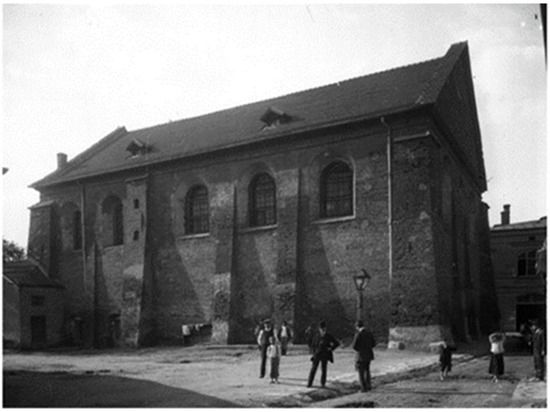
Figure 1.
New-Town synagogue photographed by Edward Janusz [27].
The photograph shows the building as it was around the second half of the eighteenth century and the beginning of the nineteenth century. The building, designed by Giovani Baptiste Belotti, underwent several transformations mainly due to fires in 1660, 1739, and 1842. The changes in the architecture of the building mainly concerned the form and shape of the roof. At first, the building was covered with a pyramid roof, then the roof was changed into a gable roof, and finally it was rebuilt as a mono-pitched roof, which it has retained up the present. Moreover, due to its defensive character, New-Town synagogue was strengthened from the outside with conspicuous buttresses. The function of the building has also changed over the years. During the Second World War, it was used as a stable and later as a warehouse by Germans who stayed in Rzeszow for some time. The synagogue, badly damaged during war, was rebuilt and restored in the 1960s. During this reconstruction, its initial architectural structure and form was modified, and its original appearance was changed in order to adapt it for use as the Art Exhibition Office. The New-Town synagogue building was included in the national register of monuments in 1978, and its historical photograph is in the collection of the Photography Gallery of Rzeszow [43].
3.2. Reconstruction on the Basis of a Single Photograph
The process of recreating an object on the basis of a photograph is possible only when the photograph meets the restitution requirements, that is, it is of good quality and its geometric content allows the use of geometric constructions that enable restitution. Restitution requirements vary depending on the purpose of the reconstruction. For special purposes, such as technical documentation, one should rely only on accurate and reliable data as well as clear geometry. However, in the case of photographs taken with a camera the calibration of which is not known, it is only possible to reconstruct the object from the photograph in accordance with the principles of projective geometry. According to projective geometry rules, each perspective image is treated as an intersection of projection rays with the projection plane. The rays go through the centre of projection, which is regarded as the eye of the observer. In this way, a natural view of the object can be obtained.
It is evident that the photograph of New-Town synagogue selected for the purpose of reconstruction is black and white and shows a building in a perspective view. The quality of the photograph seems to be sufficient for reconstruction as the contour lines of the monument are clear and its details are visible. The first step necessary to start the reconstruction was to determine the type of perspective projection used in the image, and, based on these findings, to determine the basic elements of perspective. Since the parallel lines in the photograph intersect at the proper points and the vertical lines such as wall and window edges appear parallel and remain vertical, it can be concluded that the photograph shows a two-point vertical perspective of the building (Figure 2).
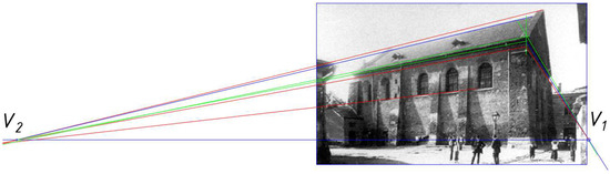
Figure 2.
Assessment of the accuracy of the photograph by checking parallelism [27].
The conclusions that can be drawn from analyzing the photograph are as follows: the building is regular and symmetrical, and the repetition of some building components can be seen.
On the basis of the intersection points of parallel lines it could be established the vanishing points and the horizon line h (Figure 3). The accuracy of the photograph and its suitability for reconstruction were confirmed by the perpendicularity of the vertical lines to the horizon line. As in previous research [27], in order to establish a principal point, the angle between a diagonal of the rectangular building plan and one of its sides was used. The intersection of line l with a circle with diameter V1V2 gave a projection center after rotation. This allowed us to establish a principal point and the radius of the circle o, a circle of depth, so the rest of the base perspective elements were important for restitution. According to the method developed by the authors in a previous publication [28], the base line p was established in parallel with the horizon line h, and it intersected one of the vertices of the rectangle parallel to the building plan.
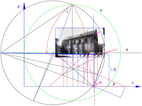
Figure 3.
The base constructions for restitution, including the locations of both the main projection PS and the auxiliary projection PSO of point P [27].
For the purpose of reconstruction, this rectangle was treated as equivalent to the base of the building.
The reconstruction of the synagogue on the basis of the photograph was carried out in accordance with the method shown in [28], where the process of reconstruction was supported by Mathcad software. Here, Mathcad was used for calculation. However, AutoCAD software was used for the estimation of the Cartesian coordinates (v, d) of the characteristic perspective points, calculated on axes v and d (Figure 4). This is because a linear perspective projection onto a projection plane τ from a viewpoint S and with a base plane π ⊥ τ can be treated as a partly composed representation [28]. Therefore, the perspective image of any point F is a pair of two points (AS, AOS), where AS is a central projection of the given point A onto a projection plane τ, i.e., a main projection, whereas AOS is a central projection of the orthogonal projection of the point A onto the base plane π, i.e., an auxiliary projection (Figure 4a,b).
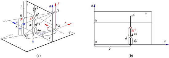
Figure 4.
Perspective projection (AS, AOS) of the point A: (a) construction of the perspective images on the projection plane τ; (b) mapping of the projections on the projection plane τ.
As has been shown in the Figure 4a, the position of any point A is determined by means of the spatial Cartesian coordinate system x, y, z, where the x, y axes are horizontal and the y is parallel to the projection plane, whereas axis z is vertical. On the other hand, the location of the points (AS, AOS) on the projection plane is described by two coordinates, v and d, given in the Cartesian coordinate system v, d (Figure 4b). In fact, the factors describing the position of the projection views are d and do, where d is the distance of the perspective projection of the point A from the base line p, whereas do is the distance of the perspective projection of the point AO from the base line p. In [22,23,24,25,26] the possibility of computer-aided perspective mapping of a line passing through two points located in space has been shown. In turn, in [27,28,29] the possibility of using a reverse algorithm that allows for the determination of a point A in space having its main AS and auxiliary AOS projections has been shown. This method was used in reconstructing the synagogue. Therefore, the main and auxiliary projections of the characteristic points of the synagogue were established in the photograph. An example point is the corner point P of the building, and its main PS and auxiliary POS projections are shown in Figure 3. The respective distances do and d of points POS and PS from the base line p were determined on the photograph. This, in turn, according to the algorithm presented in [28], allowed for the determination of the parameters w and k, according to Equations (1) and (2) Figure 4a.
The above parameters define the position of a point in space, i.e., its Cartesian coordinates x, y, z of the fixed Cartesian coordinate system (Figure 4a). However, for our purposes, Equations (1) and (2) have been modified due to the fact that they refer to the coordinates of building points included in a bottom ground plane. In this case, the calculations were based on the coordinates of the characteristic points included in the base rectangle plane, which is lower than the ground plane. Therefore, the parameter w(v, do, d), which is the distance of the reconstructed point from the base plane, had to be reduced by the distance between the ground plane and the base plane. Further, due to the fact that the restituted object exists, it was possible to measure the length of the shorter side of the building presented in the perspective image. While it is true that the building has undergone some transformations over the years, in general the building plan has not changed. Obtaining one measure value allowed us to scale the other obtained measure values of the 3D synagogue model. This enabled us to prepare the 3D model by means of AutoCAD software using the calculated measure values of the characteristic edges (Figure 5).
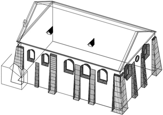
Figure 5.
The 3D synagogue model obtained by reconstruction from a single photograph.
3.3. Reconstruction by Means of Laser Scanning
At first, the feasibility of a successful laser scanning was checked. The New-Town synagogue that was the object of the scanning is located in the city center and is an accessible and visible object. In order to eliminate the influence of traffic on the measurement results, the morning hours were selected as the scanning time.
The starting point of this part of the survey was data collection, which was carried out using terrestrial laser scanning. Specifically, the measurements were obtained by means of the laser scanner Faro Focus 3D, located on a tripod (Figure 6) [42]. Targets, such as the spheres, were used as the reference points.
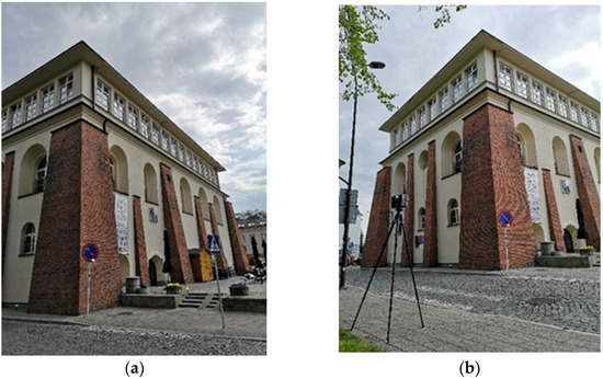
Figure 6.
Views of the New-Town synagogue: (a) south elevation; (b) the location of the scanner in relation to the south and west elevations and the target point.
The laser scanning of the synagogue was performed from six positions, that is, six outdoor measuring stations whose locations are shown in Figure 7.
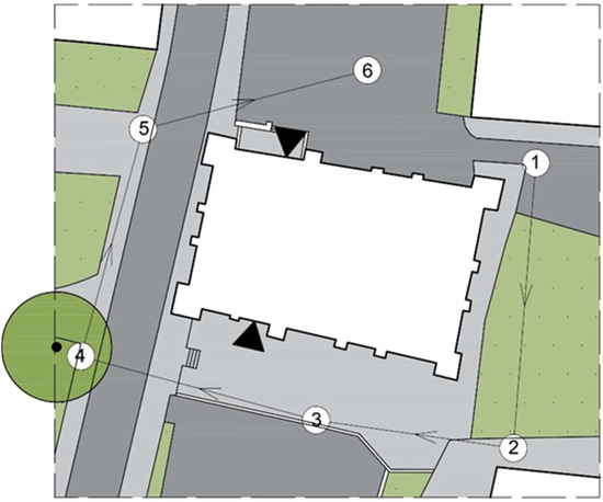
Figure 7.
The locations of the six outdoor measuring stations around the synagogue.
Two people were involved in the study. The scanning time at each scanner position was approximately nine minutes. In contrast, the total time needed to make the measurements, including the setting up of the equipment, its calibration, and data acquisition, was approximately four hours. The point cloud of the synagogue constructed according to these measurements is presented in Figure 8.
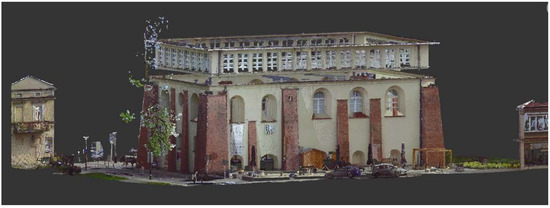
Figure 8.
The point cloud of the synagogue constructed according to the received measurements.
During the measurement acquisition process, a scan registration in color and the scanning profile “Outdoor 20 m…” were selected. The size of the scan in points was 10,242 × 4339 (horizontally × vertically). The scanner software resolution was set at ¼, i.e., 6.136 mm/10 m (10,240 pt/360°). As the result of the scanning, six outer scans were registered using the Faro Scene software [42]. The reference points, such as the spheres, were detected automatically and then verified manually to add missing targets and remove wrongly detected ones. The data set with the registered point cloud composed of 129.92 million points from all scanning positions was downloaded from the scanner. Pre-processed raw scan data as point clouds composed of the points of the external surface of the building were positioned and oriented using their own coordinate systems. The exemplary building elevations obtained as the result of the scanning are presented in Figure 9.
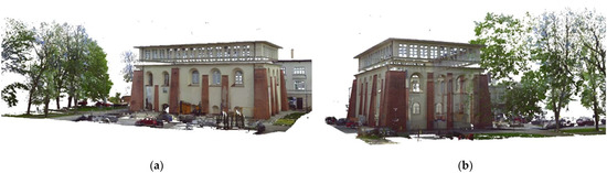
Figure 9.
Current synagogue elevations obtained by scanning: (a) the south-eastern elevation; (b) the northwestern elevation.
The final modeling of the New-Town synagogue based on the point cloud was carried out manually using Autodesk Revit 2022 software [39]. The resulting solid model of the synagogue is shown in Figure 10.
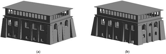
Figure 10.
The New Town synagogue models obtained as a result of laser scanning: (a) the south-eastern elevation; (b) the northwestern elevation.
3.4. Comparison of the Synagogue Models Obtained using Both Methods of Reconstruction
The final step of our research was a comparison of the previously presented models obtained by laser scanning and by reconstruction from a single photograph (Figure 11). A general assessment of the obtained models led us to conclude that over the years the general appearance and the shape of the synagogue have changed. The building has been extended vertically. However, the overall dimensions of the building and the old parts of the facade have not changed significantly, though the roof has changed. Specifically, the gable roof has been replaced with a flat one. In order to evaluate the method of reconstructing the building on the basis of photographs, the measurements of the characteristic edges of the model’s elevation were made, and these were then detailed on the synagogue model obtained by reconstruction based on a photograph. These are highlighted in red in Figure 11. The obtained linear dimensions were compared with the results of the measurements of the same edges appearing on the resulting model of the synagogue reconstruction obtained by means of laser scanning.
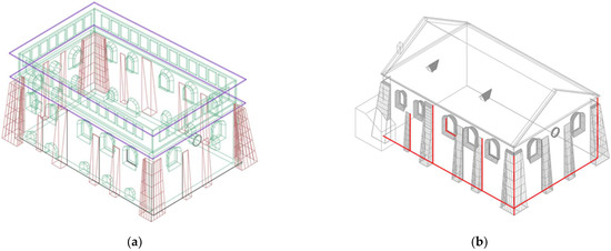
Figure 11.
The New Town synagogue models: (a) the model obtained as a result of laser scanning; (b) the model obtained by reconstruction from a photograph, with marked edges that have been verified.
Moreover, a comparative coefficient was introduced, which is the proportion of the current length of the edge of the building to the old length obtained as a result of measuring the model of the historic building reconstructed from the photograph. The obtained results are summarized in Table 1.

Table 1.
The comparison of the lengths of the characteristic edges of the current building model with the lengths of the same edges of the reconstructed model from the photograph.
4. Discussion
Based on the reconstruction results obtained from a single photograph, as well as those obtained from laser scanning, it can be concluded that the building was extended vertically. Numerous windows were placed in the superstructure of the building. The roof was changed from a gable roof into a flat one. However, the windows in the old parts of elevations and buttresses have remained almost unchanged. The comparison of the lengths of the individual edges of the building obtained from the model created on the basis of the photograph and the model obtained as a result of laser scanning allowed us to conclude that the developed method of reconstructing objects on the basis of photographs is accurate. The obtained C/F ratio, presented in Table 1 for the measured edges, seems to be satisfactory for the adopted reconstruction method. Moreover, due to the renovation works carried out, it cannot be assumed that the individual dimensions remained 100% unchanged, so the potential difference in length between the measured edges may be smaller.
This research has shown that three-dimensional reconstruction from a single photograph using the presented method is possible and can give satisfactory results. However, an architectural object can only be recreated with measurement accuracy if additional object information is available, or when it is possible to compare the building to surrounding buildings. The main preliminary information needed for reconstruction from a single image is the parallelism of the straight edges of the building. However, as a rule, parallel edges can always be distinguished in man-made historical architectural objects. Establishing base elements of perspective is always a starting point for reconstruction, whereas the method of perspective representation used depends on the location of the depicted object in relation to the projection plane. Therefore, when using a photograph taken with a camera of unknown calibration, it is necessary to rely on geometric rules of perspective projection. The accuracy of the applied method of reconstruction depends on the image accuracy. However, the results of the survey have shown that it is sufficient for historical reconstruction.
By juxtaposing two completely different reconstruction methods, it can be concluded that laser scanning is very useful for model entities as they exist in reality, whereas photograph-based reconstruction can be used when the object being restored no longer exists. Research has shown that both methods can be used interchangeably. However, both methods have pros and cons. The process of creating 3D models from point clouds requires high geometric data input to interpret the scene as well as the additional information to make the process effective. Reconstruction on the basis of a single photograph does not allow for the creation of a 3D model that precisely takes into account all four facades of a building. In the adopted solution, it was assumed that the synagogue building was built on a rectangular plan. However, the measurements obtained by means of the laser scanner have shown that the building plan is not rectangular, as the north and south walls of the building are not parallel (Figure 7). This may also account for the discrepancies in the obtained measurements. Therefore, in order to perform the 3D reconstruction of a building, it is necessary to base it on at least two photographs showing all elevations and remaining in a certain geometrical relationship. Research has shown that the reconstruction methods used for architectural objects depend on the available information as a starting point. The combination of the information and the method requires geometrical knowledge to obtain a 3D model. Geometric reconstruction from a single image is possible and necessary in the case of non-existent historical buildings, for which it is not possible to apply advanced image processing techniques. The obtained results may be useful in the case of reconstruction for tourism and historical research, as well as for social and cultural reasons, e.g., in order to strengthen the sense of identity within a region. This research will be continued when two photographs can be used in computer-aided reconstruction, and the results will be combined with those obtained from the point cloud. The aim is to develop a blended method that will enable the use of reconstruction from at most two photographs, when they exist, and when the object is impossible to scan because it has suffered a loss of its architectural elements, or alternatively to scan existing parts of the building when they are not in the photographs, taking into consideration the historic and architectural character and integrity of the chosen heritage building.
Author Contributions
Conceptualization, J.D.; methodology, J.D. and A.P.; software, J.D. and A.P.; validation, J.D.; formal analysis, J.D. and A.P.; investigation, J.D. and A.P.; resources, J.D. and A.P.; data curation, J.D. and A.P.; writing—original draft preparation, J.D.; writing—review and editing, J.D.; visualization, J.D. and A.P.; supervision, J.D.; project administration, J.D.; funding acquisition, J.D. and A.P. All authors have read and agreed to the published version of the manuscript.
Funding
This research was supported by the Polish Ministry of Science and Higher Education grant to maintain research potential, grant number PB26.BP.22.001 and PB21.BP.22.001.
Institutional Review Board Statement
Not applicable.
Informed Consent Statement
Not applicable.
Data Availability Statement
Not applicable.
Conflicts of Interest
The authors declare no conflict of interest.
References
- Šekularac, N.; Ivanović-Šekularac, J.; Petrovski, A.; Macut, N.; Radojević, M. Restoration of a Historic Building in Order to Improve Energy Efficiency and Energy Saving—Case Study—The Dining Room within the Žiča Monastery Property. Sustainability 2020, 12, 6271. [Google Scholar] [CrossRef]
- Bozdogan, O.; Yaman, A.; Yilmaz, H.M. An analysis on the corrosion of a cultural heritage. Int. J. Eng. Geosci. 2022, 7, 112–127. [Google Scholar] [CrossRef]
- Barazzetti, L.; Banfi, F.; Brumana, R.; Gusmeroli, G.; Previtali, M.; Schiantarelli, G. Cloud-to-BIM-to-FEM: Structural simulation with accurate historic BIM from laser scans. Simul. Model. Pract. Theory 2015, 57, 71–87. [Google Scholar] [CrossRef]
- Prokop, A.; Nazarko, P.; Ziemiański, L. Digitalization of historic buildings using modern technologies and tools. Bud. Archit. 2021, 20, 83–94. [Google Scholar] [CrossRef]
- Styliadis, A.D. Historical photography-based computer aided architectural design: Demolished buildings information modeling with reverse engineering functionality. Autom. Constr. 2008, 18, 51–69. [Google Scholar] [CrossRef]
- Donato, E.; Giuffrida, D. Combined Methodologies for the Survey and Documentation of Historical Buildings: The Castle of Scalea (CS, Italy). Heritage 2019, 2, 2384–2397. [Google Scholar] [CrossRef]
- Apollonio, F.I.; Fantini, F.; Garagnani, S.; Gaiani, M. A Photogrammetry-Based Workflow for the Accurate3D Construction and Visualization of Museums Assests. Remote Sens. 2021, 13, 486. [Google Scholar] [CrossRef]
- Martínez, S.; Ortiz, J.; Gil, M.L.; Rego, M.T. Recording complex structures using close range photogrammetry: The cathedral of Santiago de Compostela. Photogramm. Rec. 2013, 28, 375–395. [Google Scholar] [CrossRef]
- Ozimek, A.; Ozimek, P.; Skabek, K.; Labedz, P. Digital Modelling and Accuracy Verification of a Complex Architectural Object Based on Photogrammetric Reconstruction. Buildings 2021, 11, 206. [Google Scholar] [CrossRef]
- Remondino, F. Heritage recording and 3D modeling with photogrammetry and 3D scanning. Remote Sens. 2011, 3, 1104–1138. [Google Scholar] [CrossRef]
- Styliadis, A.D.; Sechidis, L.A. Photography-based facade recovery & 3-d modeling: A CAD application in Cultural Heritage. J. Cult. Herit. 2011, 12, 243–252. [Google Scholar] [CrossRef]
- Shashi, M.; Jain, K. Usge of photogrametry in 3D modeling and visualisation of buildings. ARPN J. Eng. Appl. Sci. 2007, 2, 37–40. [Google Scholar]
- Yastikli, N. Documentation of cultural heritage using digital photogrammetry and laser scanning. J. Cult. Herit. 2007, 8, 423–427. [Google Scholar] [CrossRef]
- Tapete, D.; Casagli, N.; Guido, L.; Riccadro, F. Integrating radar and laser-based remote sensing techniques for monitoring structural deformation of archaeological heritage. J. Archaeol. Sci. 2013, 40, 176–189. [Google Scholar] [CrossRef]
- Döş, M.E.; Yiğit, A.Y.; Uysal, M. Documenting historical monuments using smartphones: A case study of Fakih Dede Tomb, Konya. Mersin Photogramm. J. 2021, 3, 53–60. [Google Scholar] [CrossRef]
- Snavely, N.; Seitz, S.N.; Szeliski, R. Modeling the world from internet photo collections. Int. J. Comput. Vis. 2008, 80, 189–210. [Google Scholar] [CrossRef]
- Arslan, O. 3D Object Reconstruction from a Single Image. Int. J. Environ. Geoinform. 2014, 1, 21–28. [Google Scholar] [CrossRef]
- Martínez-Espejo Zaragoza, I.; Caroti, G.; Piemonte, A. The use of image and laser scanner survey archives for cultural heritage 3D modelling and change analysis. Acta IMEKO 2021, 10, 114. [Google Scholar] [CrossRef]
- Waugh, D.G.; Walton, C.D. Micro-Machining of Diamond, Sapphire and Fused Silica Glass Using a Pulsed Nano-Second Nd:YVO4 Laser. Optics 2021, 2, 169–183. [Google Scholar] [CrossRef]
- Aslan, I.; Polat, N. Availability of Iphone 13 Pro Laser Data in 3D Modeling. Adv. LiDAR 2022, 2, 10–14. [Google Scholar]
- Garcia-Gago, J.; Gomez-Lahoz, J.; Rodríguez-Méndez, J.; González-Aguilera, D. Historical Single Image-Based Modeling: The Case of Gobierna Tower, Zamora (Spain). Remote Sens. 2014, 6, 1085–1101. [Google Scholar] [CrossRef]
- Dzwierzynska, J. Computer-Aided Panoramic Images Enriched by Shadow Construction on a Prism and Pyramid Polyhedral Surface. Symmetry 2017, 9, 214. [Google Scholar] [CrossRef]
- Dzwierzynska, J. Direct Construction of an Inverse Panorama from a Moving View Point. Procedia Eng. 2016, 161, 1608–1614. [Google Scholar] [CrossRef]
- Dzwierzynska, J. Conical Perspective Image of an Architectural Object Close to Human Perception. IOP Conf. Ser. Mater. Sci. Eng. 2017, 245, 052099. [Google Scholar] [CrossRef]
- Dzwierzynska, J. Computer-aided inverse panorama on a conical projection surface. Inverse Probl. Sci. Eng. 2018, 27, 863–886. [Google Scholar] [CrossRef]
- Dzwierzynska, J. Descriptive and Computer Aided Drawing Perspective on an Unfolded Polyhedral Projection Surface. IOP Conf. Ser. Mater. Sci. Eng. 2017, 245, 062001. [Google Scholar] [CrossRef]
- Dzwierzynska, J. Single- image-based Modelling Architecture from a Historical Photograph. IOP Conf. Ser. Mater. Sci. Eng. 2017, 245, 062015. [Google Scholar] [CrossRef]
- Dzwierzynska, J. Reconstructing Architectural Environment from a Perspective Image. Procedia Eng. 2016, 161, 1445–1451. [Google Scholar] [CrossRef]
- Dzwierzynska, J. Reconstructing Architectural Environment from a Panoramic Image. IOP Conf. Ser. Earth Environ. Sci. 2016, 44, 042028. [Google Scholar] [CrossRef]
- Bourke, P. Automated 3D Model Reconstruction from Photographs. In Proceedings of the VSMM 20th International Conference on Virtual Systems & Multimedia, Hong Kong, China, 9–12 December 2014. [Google Scholar] [CrossRef]
- Farinella, G.M.; Mattiolo, G. Solutions to 3D Building Reconstruction from Photographs. In Proceedings of the Fourth Eurographics Italian Chapter Conference 2006, Catania, Italy, 22–24 February 2006. [Google Scholar]
- Hewitt, M. Representational Forms and Modes of Conception; an Approach to the History of Architectural Drawing. J. Archit. Educ. 2014, 39, 2–9. [Google Scholar]
- Leopold, C. Points of View and their Interrelations with Space and Image. In Proceedings of the Geometrias @ Graphica 2015, Lisbon, Portugal, 1–3 October 2015; pp. 365–373. [Google Scholar]
- Kalisperakis, I.; Rova, M.; Petsa, P.; Karass, G. On Multi-Image Reconstruction from Historic Photographs. In Proceedings of the XIX CIPA International Symposium, Antalya, Turkey, 30 September–4 October 2003; pp. 212–219. [Google Scholar]
- Fong, C.K.; Cham, W.K. 3D reconstruction from single perspective distorted line drawing image using vanishing points. In Proceedings of the 2005 International Symposium on Intelligent Signal Processing and Communication Systems, Hong Kong, China, 13–16 December 2005; pp. 53–56. [Google Scholar]
- Gonzalez-Aguilera, D.; Gomez-Lahoz, J.; Rodriguez-Gonzalez, P. An automatic approach for radial lens distortion correction from a single image. IEEE Sens. J. 2011, 11, 956–965. [Google Scholar] [CrossRef]
- Divya Udayan, J.; Kim, H.; Kim, J.-I. An image-based approach to the reconstruction of ancient architectures by extracting and arranging 3D spatial components. Front. Inform. Technol. Electron. Eng. 2015, 16, 12–27. [Google Scholar] [CrossRef]
- Dzwierzynska, J. Establishing Base Elements of Perspective in Order to Reconstruct Architectural Buildings from Photographs. IOP Conf. Ser. Earth Environ. Sci. 2017, 95, 032022. [Google Scholar] [CrossRef]
- Autodesk. Available online: https://www.autodesk.pl/ (accessed on 10 June 2022).
- Borodinecs, A.; Zemitis, J.; Dobelis, M.; Kalinka, M. 3D scanning data use for modular building renovation based on BIM model. In Proceedings of the MATEC Web of Conferences, Moscow, Russia, 14–16 November 2018; Volume 251, p. 03004. [Google Scholar] [CrossRef]
- Thomson, C.; Boehn, J. Automatic Geometry Generation from Point Clouds for BIM. Remote Sens. 2015, 7, 11753–11775. [Google Scholar] [CrossRef]
- FARO Knowledge Base. As-Built. Available online: https://knowledge.faro.com/Software/As-Built (accessed on 10 June 2022).
- Gałuszka, I. History of photography in Rzeszów. Renov. Monum. 2015, 3, 162–171. (In Polish) [Google Scholar]


Publisher’s Note: MDPI stays neutral with regard to jurisdictional claims in published maps and institutional affiliations. |
© 2022 by the authors. Licensee MDPI, Basel, Switzerland. This article is an open access article distributed under the terms and conditions of the Creative Commons Attribution (CC BY) license (https://creativecommons.org/licenses/by/4.0/).